Article

A Direct-Current Triboelectric Nanogenerator Energy Harvesting System Based on Water Electrification for Self-Powered Electronics

1
School of Mechanical Engineering, University of Ulsan, 93, Daehak-ro, Nam-gu, Ulsan 44610, Korea
2
School of Electrical and Computer Engineering, Ulsan National Institute of Science and Technology, Ulsan 44919, Korea
*
Author to whom correspondence should be addressed.
Appl. Sci. 2022, 12(5), 2724; https://doi.org/10.3390/app12052724
Submission received: 29 January 2022 / Revised: 25 February 2022 / Accepted: 4 March 2022 / Published: 6 March 2022

Abstract

:
This study aimed to develop a simple but effective mechanical-to-electrical energy conversion for harvesting hydrokinetic energy based on triboelectric nanogenerator (TENG) technology. Here, a direct-current fluid-flow-based TENG is reported as a potential solution to solve the inconvenience of directly powering electronic devices where direct-current (DC) power is required. The falling of a water droplet (about 1.06 mL) from an elastomeric pipe can generate an open-circuit voltage of ~35 V, short-circuit current of 3.7 µA, and peak power of 57.6 µW by passing through a separated electrode. Notably, the electrical responses have the distinct characteristics of pulsed direct current. The ability to generate DC outputs enables the TENG to directly drive electronic devices. Our experimental results prove that this TENG can act as a power source to directly light up 50 light-emitting diodes without requiring a rectifier, and, also, the produced electric energy was demonstrated that can be stored directly in a capacitor to power commercial temperature and humidity IoT sensors. Furthermore, the device shows a greatly varied output voltage based on the droplet flow rate, with a linearity R2 = 0.998. This work highlights a promising potential for applications in harvesting hydrokinetic energy and self-powered sensors and systems.

Graphical Abstract

1. Introduction

With the growth of the Internet of Things, the development of electronic devices follows a general trend of miniaturization, portability, and functionality, which require a very small power in microwatt to milliwatt level [1]. Thus, micro-/nano-technologies received extended attention from scientists, resulting in the invention of the nanogenerators, including the triboelectric nanogenerator, which was invented by Z. L. Wang’s group. The fundamental theory of TENG is based on the coupling effects of contact electrification (CE) and electrostatic induction [2]. In the last decades, TENG devices are rapidly developed with a high potential for harvesting ambient mechanical energy from the environment, such as human motion, vibrations, ocean waves, and wind energies. However, conventional TENGs exhibit alternating-current (AC) output characteristics due to the changing periodically of the distance or contact area between materials, resulting in the fact that triboelectric charges generated by CE cannot be accumulated continuously without using a rectifier unit. It would be inconvenient for directly powering electronic devices where direct-current (DC) power is required. In this case, a rectification method, such as bridge rectifiers [3,4,5,6], electric brushes [7,8], and power management circuits [9,10,11], is mandatory to obtain DC power from AC power. Nevertheless, a rectifier module in the electrical circuit could increase the complexity of the device, while the power consumed by the rectifier could reduce the energy utilization efficiency of TENGs. Therefore, direct-current triboelectric nanogenerators (DC–TENGs) have attracted considerable interest from researchers as a promising solution to solve the above problems. It believes that the ability to generate DC power enables DC–TENGs to have great potential for practical applications with advantages for the miniaturization of self-powered systems and the high efficiency of energy storage [12,13,14,15].
In particular, numerous fluid-based triboelectric nanogenerators (FluTENGs) have been developed to harvest fluid flow energy, including airflow and water-flow energies [16,17,18]. Notably, FluTENGs relying on water-based CE have been demonstrated as a new approach for harvesting low-frequency and small-scale energy from moving water, such as waterdrops/raindrops [19,20,21,22], water streams [23,24,25], and water waves energies [26,27,28]. Considering fluid-based DC–TENGs, J. Wang et al. [8] proposed a direct-current rotary-tubular TENG based on liquid-dielectrics contact, in which produced electricity can directly charge the capacitor without a rectifier unit and act as a power source to drive a thermometer after a charging time. Similarly, T. Kim et al. [15] reported a DC–TENG via water electrification and phase control that can generate DC power without any converters or batteries. J. Nie et al. [29] proposed a liquid–liquid TENG that can produce DC power owing to the contact-separation between a water droplet and a conductive liquid membrane. Y. Song et al. [30] reported a concept wherein DC electricity can be generated from a droplet falling into an electrolyte solution. This is mainly due to the dynamic wetting of a pair of copper electrodes immersed in the electrolyte. Additionally, droplet-based electricity generators proposed by W. Xu et al. and N. Zhang et al. [31,32] prove an important contribution of the metal electrode in the charge-transfer process between the insulating layer and the electrode when water is in contact with both, resulting in enhancing output performance of their TENGs. Moreover, X.-H. Hou et al. [33,34] demonstrated that a unidirectional current can be generated because of the friction when water/oil flows through a metal pipe. J. Y. Hwang et al. [35] also reported a DC-power-harvesting system by using streaming electrification and an opposite charge extractor. Furthermore, G. H. Nam et al. [36] reported a new pathway for liquid–solid TENG, using streaming flow by a novel direct charge transfer, where the DC output is produced as a result of the unidirectional charge transfer from water flow into the electrode. Accordingly, electrons can directly transfer from one side to the other at the contact interface when the water contacts a metal surface [37,38]. This implies a promising technology for harvesting hydrokinetic energy by developing a DC–TENG based on contact electrification and direct charge transfer at the water–metal interfaces.
In this paper, we report a direct-current fluid-flow-based triboelectric nanogenerator, the so-called DC–FluTENG, which offers a simple but effective mechanical-to-electrical energy conversion technology for harvesting hydrokinetic energy. DC–FluTENG is based on an extremely simple structure with a metal electrode located near the outlet of a pipe and working in a single-electrode mode. This is different from a conventional single-electrode-based TENG, where the electrode is placed below the charge-generating layer. Consequently, the moving of a water droplet (about 1.06 mL) can produce a peak DC voltage and current of about 35 V and 3.7 µA, respectively, by passing through an elastomeric pipe under a single-electrode mode of operation. Experimental results prove that the proposed TENG can produce a maximum instantaneous power of 57.6 µW under an optimal external load of 10 MΩ at a droplet flow rate of 676 mL/min. This device can generate a transferred charge density of about 14.95 mC/m2. More importantly, DC–FluTENG can act as a DC power source to light up directly 50 light-emitting diodes (LEDs) without requiring a rectifier, and, also, the produced electric energy was demonstrated that can be stored directly in a capacitor to power commercial temperature and humidity IoT sensors. Moreover, the device showed a greatly varied output voltage based on different water-flow rates with a linearity R2 = 0.998. This work highlights the great potential of DC–FluTENG for practical applications as an energy harvester and a self-powered flow-rate sensor.

2. Materials and Methods

2.1. Experimental Installation and Process

The experimental measurement of DC–FluTENG was carried out on the system as shown in Figure 1a. Among the experimental apparatus, a microprocessor-controlled tubing pump of ISMATEC–Ecoline VC-360 with an Tygon silicone tubing manufactured by Saint-Gobain Performance Plastics (6.4 mm inner diameter, 1.6 mm thickness, and 90 cm length) was used to generate the flow of water droplets in the system. The fabrication of a DC–FluTENG cell is extremely simple, with a pin-type electrode (0.5 mm in diameter and 30 mm in length) located at a distance of 5 cm from the end of a pipe and connected to the ground, resulting in a single-electrode mode of operation. The average contact area between the droplet and the electrode is about 10 mm2. A Digit Graphical Sampling Multimeter model DMM7510 of the Keithley Instruments, Inc. (Cleveland, OH, USA) (this measuring instrument has an enhanced accuracy DC-current function that can measure a 1 µA sleep mode current with 1 pA resolution and with 0.375 nA tolerance, an enhanced sensitivity with 100 mV range with 10 nV resolution, and a high input impedance of more than 10 GΩ) was used to measure the potential and current from the electrode to the ground. To evaluate the output performance of the TENG, deionized water, tap water, and 0.3 M copper sulfate (CuSO4) solution were used as the test water; meanwhile, silver, gold, copper, and aluminum were considered as the material of electrodes. Simultaneously, various capacitors with capacitance in a range from 1 to 100 µF and resistors with resistance in a range from 10 kΩ to 50 MΩ were utilized as the external electrical loads to find out the optimal working conditions of the system. The droplet flow rates were controlled in a range from 113 to 676 mL/min.
Based on the representative component layers of a conventional single-electrode-based TENG, the charge-generating layer and charge-collecting layer (electrode) are normally affixed together. However, in the case of DC–FluTENG, the electrode is completely separated from the charge-generating layer (pipe), which indicates an improved single-electrode configuration. It leads to the difference in output characteristics of the DC–FluTENG and conventional SE-TENGs. Conventional SE–TENGs normally come out with alternating current outputs, and then a rectifier module is needed to convert the AC output into DC output before powering electronic devices. Meanwhile, DC–FluTENG exhibits direct-current outputs that can power directly electronic devices without requiring a rectifier. This is an advance in comparison with conventional SE–TENGs, as shown in Figure 1b.

2.2. Working Principle of DC–FluTENG

The fundamental theory of a liquid–solid TENG relates to the formation of the electrical double layer (EDL), consisting of an inner layer (or Stern layer) and a diffuse layer, at the liquid–solid contact interfaces. When water comes into contact with a solid surface, the ions existing in the water, such as H3O+, OH, and other positive/negative ions, form an electrical double layer. According to the “two-step” model proposed by Wang et al. [2], the origin of forming EDL was demonstrated as the result of CE in the first step, due to the electron transfer occurring when the molecules/atoms inside the water interact directly with the atoms on the solid surface. We can assume that charges in the Stern layer are close to the solid surface, which can only move along the surface. Meanwhile, the movement of charges in the diffuse layer is not restricted to the surface. These charges can separate from the EDL and move along with the water flow. At a static state, the ions can distribute themselves in EDL, in which the concentration of the counter-ions is high near the wall and decreases dramatically away from the wall. When the water flow is applied, the diffuse layer in EDL is dragged downstream and temporarily replaced by neutral liquid. As the charges on the solid surface are immobile, the movement of ions in EDL will cause an accumulation of charges downstream and the deficit of counter-ions upstream. In this instant, counter-ions will be drawn back; meanwhile, co-ions from the EDL and liquid bulk will be pushed away by the charges on the solid surface and the accumulated charges downstream in an attempt to recover the initial EDL structure [39,40,41,42]. In other words, the diffuse layer is shrunk due to part of the diffuse layer being washed away by the flowing water. Thus, the flowing water carries part of the electric charge of the double layer and generates free electrostatic charges (excess negative), as presented in Figure 2b. The charge carried by water droplets dispensed from a capillary is studied by J. Nauruzbayeva et al. [39], which demonstrated that the droplets exposed from a water-filled capillary could carry excess negative charges.
The step-by-step illustrations of the working principle of DC–FluTENG are presented in Figure 2a. At the initial state, an EDL is formed due to CE occurring at the contact interface between water and the inner surface of the pipe (see Figure 2a(i)). At this time, no output signal is observed in the external circuit. As the droplet carries excess negative charges, when the droplet contacts the electrode, charges on the droplet can be transferred to the electrode, forming an unbalance potential between the electrode and the ground Simultaneously, positive charges from the ground are attracted to neutralize the potential, generating an immediately current of charges from the ground to the electrode via the external circuit, as seen in Figure 2a(ii). During the contact process of the droplet and the electrode, almost all of the charges on the droplet are transferred to the electrode until the potential difference between water and electrode disappears, as shown in Figure 2a(iii,iv). As the charges across the metal surface are distributed equally, the electric potential of the metal electrode is equal to zero when the droplet completely separates from the electrode (see Figure 2a(v)). Consequently, a direct current is induced from the ground to the electrode via the external circuit. Due to the continuous flow of water droplets through the system, the electricity-generation process is repeated.

3. Results and Discussion

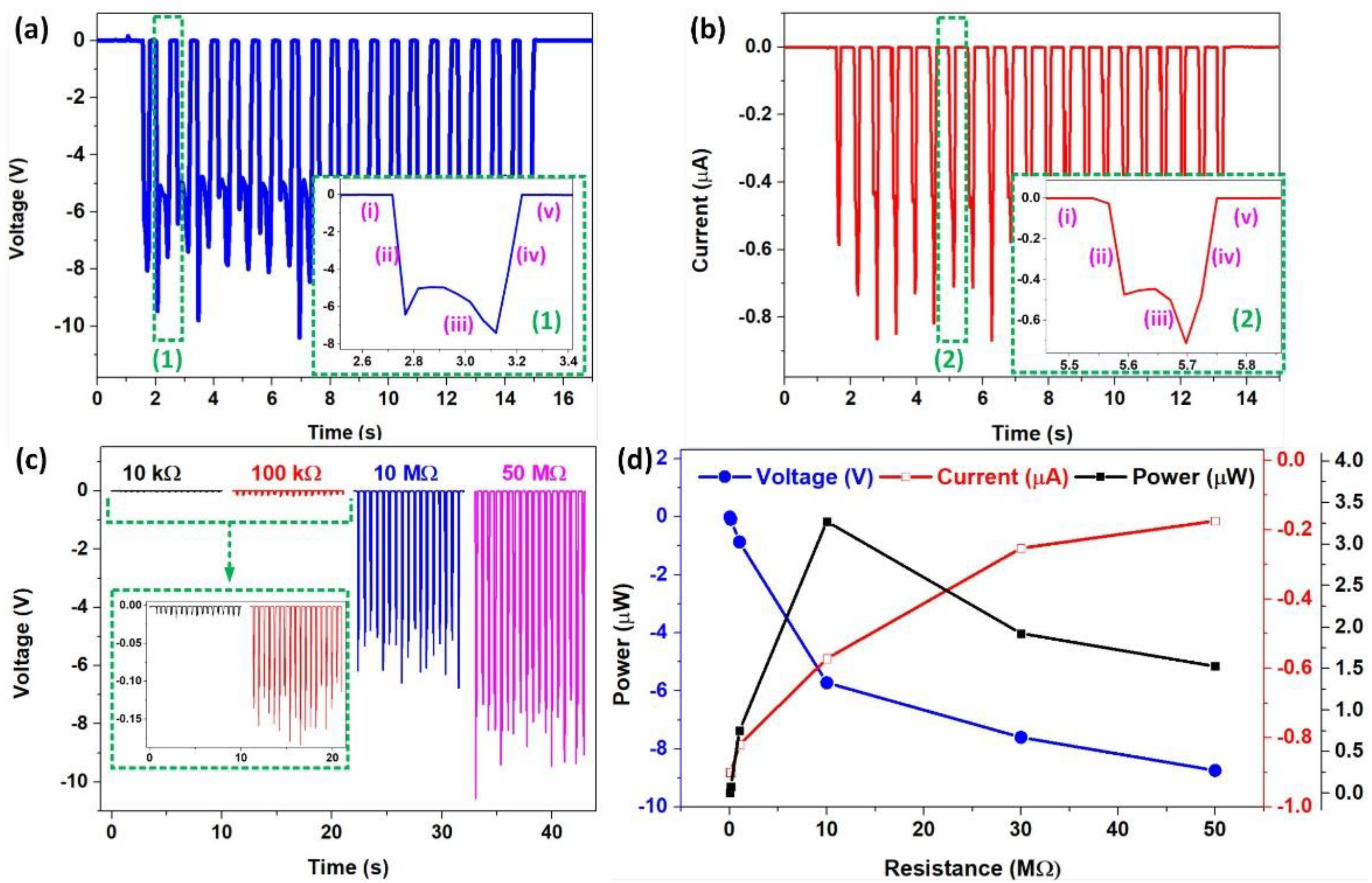
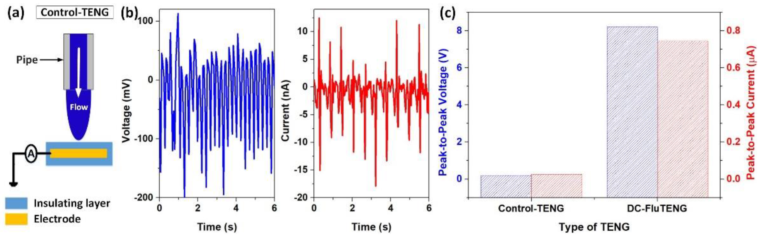
3.1. Electricity Generation of DC–FluTENG

To evaluate the electrical characteristics of the DC–FluTENG, DI water droplets (about 1.06 mL) are delivered periodically into the system at a flow rate of 113 mL/min. Here, the aluminum electrode is used. Due to the continuous flow of water droplets, a stable open-circuit voltage (Voc) and short-circuit current (Isc) are continuously generated, as shown in Figure 3a,b. As regards these figures, both voltage and current signals are obtained as the distinct characteristics of pulsed direct current. It can be observed that, with a single droplet, DC–FluTENG can produce an average Voc of −8.1 V and an average Isc of −0.757 µA, corresponding to a maximum charge transfer of 78 nC (calculated in short-circuit mode). Herein, the negative sign (−) represents the direction of the electric current according to the electrical measurement setup, that is, from the ground to the electrode. The inset images present the correspondence between typical pulses of Voc and Isc and the step-by-step process mentioned in the above section. Obviously, the pulse outputs are observed when water and the electrode are in contact, in which the signal exhibits a large acceleration from zero and deceleration to zero at the beginning and the end of the contact-separation process, respectively; during the contact, the output signal fluctuates around an average value; otherwise, no electrical signal is produced in the whole circuit.
To confirm the DC output characteristics of the device, the electrical responses of DC–FluTENG are examined by connecting a resistor with a range of load resistance between the electrode and the ground. The output voltages plotted in Figure 3c clearly show the DC characteristics of the output voltage with all negative pulses. Notice that the magnitude of the output voltage is considerably increased when increasing the load resistance from kiloohm to megaohm level. The changes of average magnitudes of both voltage and current based on the load resistance imply an opposite trend, as reported in Figure 3d. Regarding the increase of load resistance from 10 kΩ to 50 MΩ, the magnitude of output voltage increases from 9 mV to 8.7 V; meanwhile, the peak current decreases from 0.9 to 0.173 µA, respectively. This figure also displays the summarization of the instantaneous power ( P i n s ) concerning loading resistances. By varying the load resistance from 10 kΩ to 10 MΩ, the value of P i n s dramatically increases from 8 nW to 3.27 µW. However, as the load resistance exceeds 10 MΩ, P i n s is reduced and reaches a value of 1.53 µW at 50 MΩ. Thereby, we believe that there certainly exists an optimal load resistance; here, it is 10 MΩ, where the maximum output power is achieved. Thereby, DC–FluTENG can produce a maximum peak power of 3.27 µW at a flow rate of 113 mL/min, corresponding to a power density of 0.327 W/m2, calculated based on the total contact area between the water droplet and the electrode.
In regard to another aspect, to verify that the DC outputs are generated due to the direct contact of water with the electrode, comparison experiments were conducted by covering the electrode with an insulating layer, such as polyvinyl chloride, resulting in a control single-electrode-based TENG, as shown in Figure 4a. The performance of this control-TENG was studied, and the results are shown in Figure 4b. It can be seen that both Voc and Isc are obtained AC electrical characteristics with amplitudes of about 100 mV and 11 nA, respectively. In comparison with the system shown in Figure 1, the only change made is the insulation on the electrode. It can be concluded that the DC electric pulses are generated due to the advanced electrode configuration. Notably, the peak-to-peak Voc and Isc of DC–FluTENG are approximately 40 times and 28 times higher than those of the control-TENG, which declares a great enhancement in the output performance of DC–FluTENG, as presented in Figure 4c.

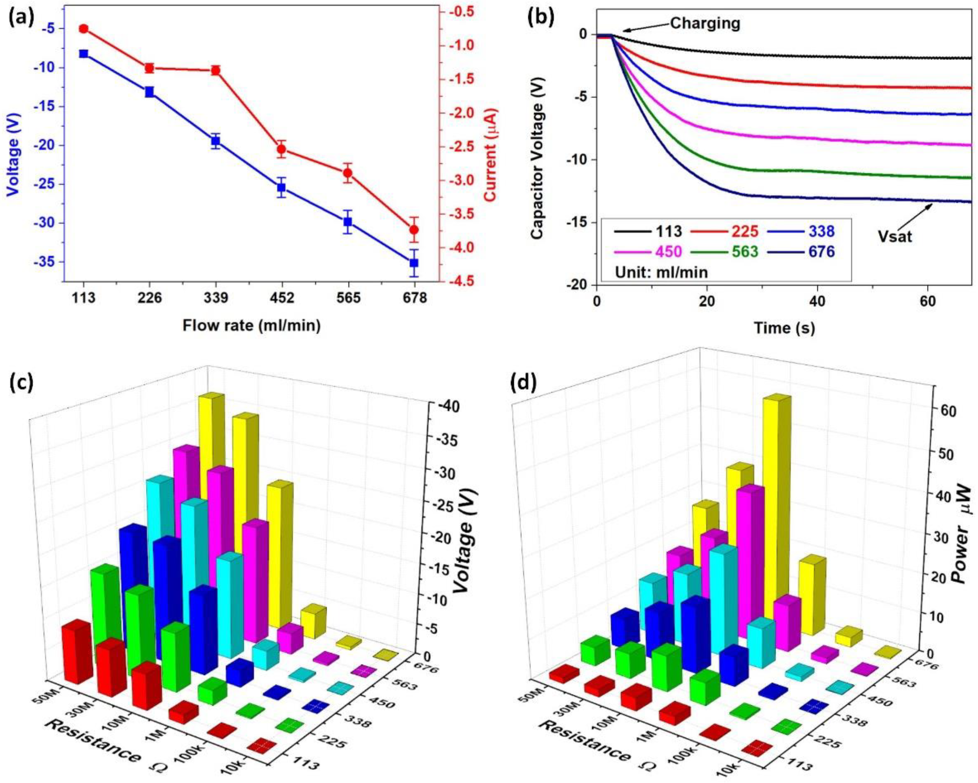
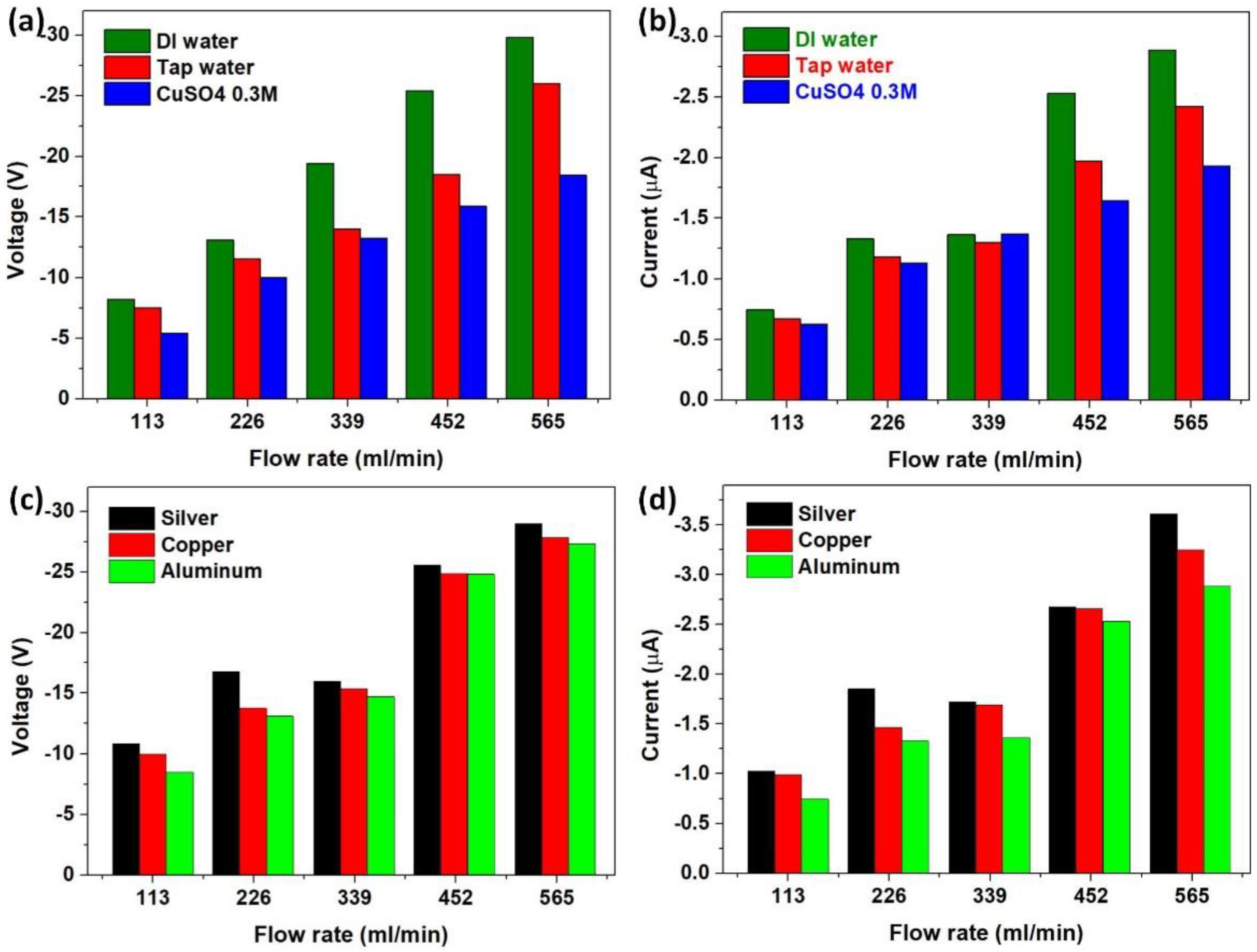
3.2. Factors Affecting the Output Performance

To evaluate the factors affecting the output performance, the experiments are realized at different flow rates of water droplets, which are controlled in a range from 113 to 676 mL/min. Typical electrical output signals, including the Voc and Isc, are illustrated in Supplementary Materials Figure S1a,b, respectively. From these figures, we can see that the voltage and current signals have similar DC characteristics with all negative pulses. It is considered that a rising trend occurs for both magnitudes of voltage and current output as the flow rate increases. Following the changes in the average magnitudes of voltage and current output summarized in Figure 5a, we see that the magnitude of Voc increases from 8.1 to 35.1 V, while the value of Isc increases from 0.757 to 3.728 µA when increasing the flow rate from 113 to 676 mL/min, respectively. Similarly, an identical trend is found for the transferred charges in short-circuit mode, where its value increases from 78 to 149.6 nC monotonically. This is mainly due to the increase of accumulative triboelectric charges generated by the water flow.
More interestingly, generated electric energy can directly charge an energy storage unit without requiring a rectifier unit. The charging capability concerning the flow rate is studied by measuring the voltage developed across a 1 µF capacitor in the external circuit. The charging behaviors are plotted in Figure 5b, where the maximum measured voltage is obtained at a flow rate of 676 mL/min with a value of about −13.3 V, corresponding to a maximum amount of 88.45 µJ energy stored. Additionally, the impact of the water-flow rate on the output performance is also investigated by applying various load resistance in the external circuit with a range from 10 kΩ to 50 MΩ. The average voltage and instantaneous power are respectively represented in Figure 5c,d. At the same load resistance, the magnitudes of both the peak voltage and maximum instantaneous power are monotonically increasing with the flow rate. Meanwhile, for each applied flow rate, the highest values of power output are found at the optimal loading resistance of 10 MΩ. Consequently, the highest output power obtains a value of 57.6 µW regarding the power density of 5.76 W/m2, as measured at the load resistance of 10 MΩ under a flow rate of 676 mL/min.
Another important aspect to examine is how material selection affects the output performance of the DC–FluTENG. The experiments are realized based on different types of water, such as DI water, tap water, and 0.3 M CuSO4 solution, and different materials of the electrode, such as silver, copper, and aluminum. Supplementary Materials Figure S2a,b displays the voltage and current curves when passing water droplets through contacting an aluminum electrode at a flow rate of 113 mL/min. It seems that both output the Voc and Isc produced by DI water are higher than those by two other types of water. This is mainly caused by the presence of electrolytes in the water droplet. In general, the water cannot be completely separated from the electrode; residual water always exists on the electrode surface. If the water contains electrolytes, a partial screening of the triboelectric charges on the surface due to positive charges, including dissolved ions that remain on the electrode surface, is required. This explains why the electrical responses in the case of tap water and 0.3 M CuSO4 solution are smaller than those obtained from DI water. Considering the case using tap water and 0.3 M CuSO4 solution, the output currents reach −0.675 and −0.627 µA, which are 89% and 83% of that generated by DI water, respectively. Similarly, the voltages produced from these two types of water are approximately 93% and 69% of that generated by DI water (−8.1 V). As resumed in Figure 6a,b, the dependence of the average magnitudes of Voc and Isc on the water-flow rate verifies the highest performance of DI water in comparison with other types of water.
In the same manner, silver, copper, and aluminum were selected as the material of the electrode to examine the output performance of the device. The output Voc and Isc are illustrated in Supplementary Materials Figure S2c,d; here, DI water was used as the test water. It can be seen that the silver electrode can produce a higher output voltage and current than those produced by other metal electrodes. There is a slight difference of about 10% in the average magnitude of Voc and Isc between silver and copper electrodes, whilst the output of the aluminum electrode is only about 75% of that generated by the silver electrode. Thus, the silver electrode can generate a higher output than copper and aluminum can. This arrangement in output performance could relate to the conductivity of these metals, in which silver is the best conductor. On another hand, the experimental data shown in Figure 6c,d declare the rising trend of the magnitude of the output signals with the increase of water-flow rate.
Importantly, these experimental results can prove the versatility of DC–FluTENG in generating DC output from a wide range of environments. Moreover, it can conclude that, by increasing the water-flow rate, the output performance of the device will be increased. Moreover, the presence of electrolytes in water could reduce the electrical outputs, and the conductivity of the electrode has a positive relationship to output performance.

3.3. Application of DC–FluTENG

DC-FluTENG is proposed as a simple mechanical-to-electrical energy conversion from harvesting hydrokinetic energy. Indeed, DC power can be produced due to the continuous flow of water droplets through a pipe and a metal electrode. The dependences of power density on the flow rate and loading resistance are represented in Figure 7a. At the optimal load resistance of 10 MΩ, the power density increases from 0.327 to 5.76 W/m2 when increasing the flow rate from 113 to 676 mL/min, respectively. Obviously, by increasing the water-flow rate to 6 times, the output power density increases more than 17 times, which proves a considerable influence of water flow rate on the power generation performance of the device. As the power density of DC–FluTENG is much higher than those of 1.74 mW/m2 in [43], 27.86 mW/m2 in [44], 170 mW/m2 in [45], and 590 mW/m2 in [24], it declares a dramatic enhancement in output performance compared to other droplet-based TENGs, particularly AC-type devices. The transferred charge density ( J t c ) and electrical energy density ( J e e ) regarding the water flow rate are shown in Figure 7b, in which J t c increases from 7.8 to 14.95 mC/m2 and J e e increases from 3.1 to 377.9 mJ/m2 when the flow rate increases from 113 to 676 mL/min, respectively. These results can demonstrate the potential application of DC–FluTENG as an energy harvester.
Moreover, the ability to generate DC output enables the TENG to directly drive electronic devices. DC–FluTENG is integrated into a self-powered IoT sensors device and acts as a power source, as described in Supplementary Materials Figure S3a. DC power generated by the TENG can be used to directly charge an energy storage unit, such as a capacitor, without requiring a rectifier. The actual experiments are demonstrated in Supplementary Materials Figure S3b and Video S1. The charging behaviors plotted in Figure 7c were examined by using different capacitors from 1 to 100 µF. It can be observed that larger capacitances have to take more time to achieve the saturation voltage. Under a droplet flow rate of 113 mL/min, to attain a voltage of about 2 V, a 100 µF capacitor needs more than 270 s, while a 10 µF capacitor can reach 2 V within 20 s. However, at the same period, a 1 µF capacitor can be charged to 10 V. This is important to find out the optimal load capacitance in achieving the maximum energy storage. To demonstrate the application of the device as a power source in IoT sensing systems, a commercial Internet of Things (IoT) device, namely Solar-Powered BLE Beacon of Cypress Semiconductor Corporation company, is used. This IoT device could be powered by DC–FluTENG instead of the solar part which is removed. The room temperature and humidity signals are transmitted to the smartphone via Bluetooth after charging in the capacitor within 20 s; here, a 1 µF capacitor was utilized. The actual experimental operation is shown in Figure 7e and Supplementary Materials Video S2. In addition, DC–FluTENG not only can charge the energy storage unit directly but also power electronics directly. In this work, light-emitting diodes (LEDs) can be utilized to verify the application of the TENG. As shown in the inset image of Figure 7f, 50 LEDs in series can be illuminated by connecting directly with the DC–FluTENG without a rectifier, thus indicating another advantage of the TENG in practical applications. It can also be demonstrated in Supplementary Materials Video S3, the actual experimental operation. These results prove that DC–FluTENG can be effectively utilized to directly drive electronics; thus, it shows a high potential application value.
Another important aspect, DC–FluTENG, which is based on different water-flow rates, shows a greatly varied output voltage; hence, the output voltage can be applied as a self-powered sensor for active water-flow control. Figure 7d provides the linear regression analysis that models the relationship between the output Voc and the input flow rate. We can observe a strong linear relationship with the linear regression curve given by V = K.Q + V0 (V), where K is the sensitivity, Q is the flow rate, and V0 is the intercept. The results show a high sensitivity of about 48.4 mV/cc⋅min and a linearity R2 = 0.998, which indicate a great accuracy and potential application for measuring the water-flow rate. As a result, the value of the flow rate can be predicted based on the measured output voltage.

4. Conclusions

In summary, the direct-current fluid-flow-based triboelectric nanogenerator was demonstrated to be a simple and effective mechanism for mechanical-to-electrical energy conversion from flowing water. The falling of a water droplet from a pipe can generate a direct current in the external circuit by contacting a separated electrode. This is different from a conventional single-electrode TENG that has the distinct characteristics of AC. Experimental results prove that the device can produce DC outputs with an open-circuit voltage of 35 V and a short-circuit current of 3.7 µA. The maximum instantaneous power can reach 57.6 µW at a load resistance of 10 MΩ. The type and flow rate of water droplets and the material of electrodes are investigated as the factors affecting the output performance of DC–FluTENG. More importantly, the ability to generate DC output enables the DC–FluTENG to directly drive electronic devices, such as directly lighting up 50 LEDs connected in series, without requiring a rectifier. Moreover, the produced energy can be stored directly in a capacitor and used to power a commercial temperature and humidity IoT sensors device. Taking advantage of direct current outputs, both portability and energy utilization efficiency can be improved. Furthermore, the output voltage and the flow rate have a great proportional relationship, with a high sensitivity of about 48.4 mV/cc⋅min and linearity of R2 = 0.998. Based on these results, this work highlights a promising potential for applications in harvesting hydrokinetic energy and self-powered sensors systems.

Supplementary Materials

The following supporting information can be downloaded at https://www.mdpi.com/article/10.3390/app12052724/s1. Figure S1: (a) Open-circuit voltage and (b) short-circuit current of DC–FluTENG under various water flow rates in a range from 113 to 563 mL/min, Figure S2: Open-circuit voltage and short-circuit current of DC–FluTENG by using different (a,b) types of water and (c,d) materials of the metal electrode, respectively. Measured at a water flow rate of 113 mL/min. Figure S3: Application of DC–FluTENG to directly drive electronics. (a) DC–FluTENG integrated into an IoT sensors application. (b) Experiment setup for charging a capacitor directly without a rectifier. Video S1: Charge a capacitor without a rectifier. Video S2: Power an IoT sensors application without a rectifier. Video S3: Light up light-emitting diodes (LEDs) without a rectifier.

Author Contributions

Conceptualization, Q.T.N.; investigation, Q.T.N. and C.P.V.; methodology, Q.T.N. and T.H.N.; writing—original draft preparation, Q.T.N.; software, C.P.V.; validation, C.P.V.; writing—review and editing, C.P.V. and T.H.N.; supervision, K.K.A.; funding acquisition, K.K.A.; project administration, K.K.A. All authors have read and agreed to the published version of the manuscript.

Funding

This research was supported by Basic Science Program through the National Research Foundation of Korea (NRF) funded by the Ministry of Science and ICT, South Korea (NRF-2020R1A2B5B03001480).

Institutional Review Board Statement

Not applicable.

Informed Consent Statement

Not applicable.

Data Availability Statement

The authors confirm that the data supporting the finding of this study is available within the article.

Conflicts of Interest

The authors declare no conflict of interest.

References

  1. Raj, A.; Steingart, D. Review—Power Sources for the Internet of Things. J. Electrochem. Soc. 2018, 165, B3130–B3136. [Google Scholar] [CrossRef]
  2. Wang, Z.L.; Wang, A.C. On the origin of contact-electrification. Mater. Today 2019, 30, 34–51. [Google Scholar] [CrossRef]
  3. Wang, S.; Wang, X.; Wang, Z.L.; Yang, Y. Efficient Scavenging of Solar and Wind Energies in a Smart City. ACS Nano 2016, 10, 5696–5700. [Google Scholar] [CrossRef] [PubMed]
  4. Zhang, K.; Wang, X.; Yang, Y.; Wang, Z.L. Hybridized Electromagnetic–Triboelectric Nanogenerator for Scavenging Biomechanical Energy for Sustainably Powering Wearable Electronics. ACS Nano 2015, 9, 3521–3529. [Google Scholar] [CrossRef]
  5. Zhong, J.; Zhong, Q.; Fan, F.; Zhang, Y.; Wang, S.; Hu, B.; Wang, Z.L.; Zhou, J. Finger typing driven triboelectric nanogenerator and its use for instantaneously lighting up LEDs. Nano Energy 2013, 2, 491–497. [Google Scholar] [CrossRef]
  6. Zhang, Q.; Liang, Q.; Liao, Q.; Ma, M.; Gao, F.; Zhao, X.; Song, Y.; Song, L.; Xun, X.; Zhang, Y. An Amphiphobic Hydraulic Triboelectric Nanogenerator for a Self-Cleaning and Self-Charging Power System. Adv. Funct. Mater. 2018, 28, 1803117. [Google Scholar] [CrossRef]
  7. Zhang, C.; Zhou, T.; Tang, W.; Han, C.; Zhang, L.; Wang, Z.L. Rotating-Disk-Based Direct-Current Triboelectric Nanogenerator. Adv. Energy Mater. 2014, 4, 1301798. [Google Scholar] [CrossRef]
  8. Wang, J.; Wu, Z.; Pan, L.; Gao, R.; Zhang, B.; Yang, L.; Guo, H.; Liao, R.; Wang, Z.L. Direct-Current Rotary-Tubular Triboelectric Nanogenerators Based on Liquid-Dielectrics Contact for Sustainable Energy Harvesting and Chemical Composition Analysis. ACS Nano 2019, 13, 2587–2598. [Google Scholar] [CrossRef]
  9. Liang, X.; Jiang, T.; Liu, G.; Xiao, T.; Xu, L.; Li, W.; Xi, F.; Zhang, C.; Wang, Z.L. Triboelectric Nanogenerator Networks Integrated with Power Management Module for Water Wave Energy Harvesting. Adv. Funct. Mater. 2019, 29, 1807241. [Google Scholar] [CrossRef]
  10. Wang, X.; Yang, Y. Effective energy storage from a hybridized electromagnetic-triboelectric nanogenerator. Nano Energy 2017, 32, 36–41. [Google Scholar] [CrossRef]
  11. Zhao, K.; Wang, Z.L.; Yang, Y. Self-Powered Wireless Smart Sensor Node Enabled by an Ultrastable, Highly Efficient, and Superhydrophobic-Surface-Based Triboelectric Nanogenerator. ACS Nano 2016, 10, 9044–9052. [Google Scholar] [CrossRef] [PubMed]
  12. Liu, D.; Zhou, L.; Wang, Z.L.; Wang, J. Triboelectric nanogenerator: From alternating current to direct current. iScience 2021, 24, 102018. [Google Scholar] [CrossRef]
  13. Yang, Y.; Zhang, H.; Wang, Z.L. Direct-Current Triboelectric Generator. Adv. Funct. Mater. 2014, 24, 3745–3750. [Google Scholar] [CrossRef]
  14. Ryu, H.; Lee, J.H.; Khan, U.; Kwak, S.S.; Hinchet, R.; Kim, S.-W. Sustainable direct current powering a triboelectric nanogenerator via a novel asymmetrical design. Energy Environ. Sci. 2018, 11, 2057–2063. [Google Scholar] [CrossRef]
  15. Kim, T.; Kim, D.Y.; Yun, J.; Kim, B.; Lee, S.H.; Kim, D.; Lee, S. Direct-current triboelectric nanogenerator via water electrification and phase control. Nano Energy 2018, 52, 95–104. [Google Scholar] [CrossRef]
  16. Nguyen, Q.-T.; Ahn, K.-K.K. Fluid-Based Triboelectric Nanogenerators: A Review of Current Status and Applications. Int. J. Precis. Eng. Manuf.-Green Technol. 2020, 8, 1043–1060. [Google Scholar] [CrossRef]
  17. Jiang, D.; Xu, M.; Dong, M.; Guo, F.; Liu, X.; Chen, G.; Wang, Z.L. Water-solid triboelectric nanogenerators: An alternative means for harvesting hydropower. Renew. Sustain. Energy Rev. 2019, 115, 109366. [Google Scholar] [CrossRef]
  18. Chatterjee, S.; Burman, S.R.; Khan, I.; Saha, S.; Choi, D.; Lee, S.; Lin, Z.H. Recent advancements in solid-liquid triboelectric nanogenerators for energy harvesting and self-powered applications. Nanoscale 2020, 12, 17663–17697. [Google Scholar] [CrossRef]
  19. Yoo, D.; Park, S.-C.; Lee, S.; Sim, J.-Y.; Song, I.; Choi, D.; Lim, H.; Kim, D.S. Biomimetic anti-reflective triboelectric nanogenerator for concurrent harvesting of solar and raindrop energies. Nano Energy 2019, 57, 424–431. [Google Scholar] [CrossRef]
  20. Helseth, L.E. Electrical energy harvesting from water droplets passing a hydrophobic polymer with a metal film on its back side. J. Electrost. 2016, 81, 64–70. [Google Scholar] [CrossRef]
  21. Lin, Z.H.; Cheng, G.; Lee, S.; Pradel, K.C.; Wang, Z.L. Harvesting water drop energy by a sequential contact-electrification and electrostatic-induction process. Adv. Mater. 2014, 26, 4690–4696. [Google Scholar] [CrossRef] [PubMed]
  22. Stetten, A.Z.; Golovko, D.S.; Weber, S.A.L.; Butt, H.J. Slide electrification: Charging of surfaces by moving water drops. Soft Matter 2019, 15, 8667–8679. [Google Scholar] [CrossRef] [PubMed] [Green Version]
  23. Cheedarala, R.K.; Shahriar, M.; Ahn, J.H.; Hwang, J.Y.; Ahn, K.K. Harvesting liquid stream energy from unsteady peristaltic flow induced pulsatile Flow-TENG (PF-TENG) using slipping polymeric surface inside elastomeric tubing. Nano Energy 2019, 65, 104017. [Google Scholar] [CrossRef]
  24. Cheng, G.; Lin, Z.H.; Du, Z.L.; Wang, Z.L. Simultaneously Harvesting Electrostatic and Mechanical Energies from Flowing Water by a Hybridized Triboelectric Nanogenerator. ACS Nano 2014, 8, 1932–1939. [Google Scholar] [CrossRef]
  25. Cui, X.; Zhang, H.; Cao, S.; Yuan, Z.; Ding, J.; Sang, S. Tube-based triboelectric nanogenerator for self-powered detecting blockage and monitoring air pressure. Nano Energy 2018, 52, 71–77. [Google Scholar] [CrossRef]
  26. Li, X.; Tao, J.; Wang, X.; Zhu, J.; Pan, C.; Wang, Z.L. Networks of High Performance Triboelectric Nanogenerators Based on Liquid–Solid Interface Contact Electrification for Harvesting Low-Frequency Blue Energy. Adv. Energy Mater. 2018, 8, 1800705. [Google Scholar] [CrossRef]
  27. Zhao, X.J.; Kuang, S.Y.; Wang, Z.L.; Zhu, G. Highly Adaptive Solid-Liquid Interfacing Triboelectric Nanogenerator for Harvesting Diverse Water Wave Energy. ACS Nano 2018, 12, 4280–4285. [Google Scholar] [CrossRef]
  28. Xu, M.; Wang, S.; Zhang, S.L.; Ding, W.; Kien, P.T.; Wang, C.; Li, Z.; Pan, X.; Wang, Z.L. A highly-sensitive wave sensor based on liquid-solid interfacing triboelectric nanogenerator for smart marine equipment. Nano Energy 2019, 57, 574–580. [Google Scholar] [CrossRef]
  29. Nie, J.; Wang, Z.; Ren, Z.; Li, S.; Chen, X.; Lin Wang, Z. Power generation from the interaction of a liquid droplet and a liquid membrane. Nat. Commun. 2019, 10, 2264. [Google Scholar] [CrossRef] [Green Version]
  30. Song, Y.; Xu, H.; Xu, B.; Li, D. Electric current generation of a droplet falling into an electrolyte solution. Energy Convers. Manag. 2020, 212, 112791. [Google Scholar] [CrossRef]
  31. Xu, W.; Zheng, H.; Liu, Y.; Zhou, X.; Zhang, C.; Song, Y.; Deng, X.; Leung, M.; Yang, Z.; Xu, R.X.; et al. A droplet-based electricity generator with high instantaneous power density. Nature 2020, 578, 392–396. [Google Scholar] [CrossRef] [PubMed]
  32. Zhang, N.; Gu, H.; Lu, K.; Ye, S.; Xu, W.; Zheng, H.; Song, Y.; Liu, C.; Jiao, J.; Wang, Z.; et al. A universal single electrode droplet-based electricity generator (SE-DEG) for water kinetic energy harvesting. Nano Energy 2021, 82, 105735. [Google Scholar] [CrossRef]
  33. Hou, X.-H.; Yu, J.-K.; Sheng, M.-K.; Liu, Z.-Y.; Yang, X. Influence Factors of the Generation and Accumulation of Electric Charge on the Oil-Delivery Metal Pipelines. Acta Metall. Sin. (Engl. Lett.) 2017, 30, 1027–1032. [Google Scholar] [CrossRef]
  34. Hou, X.; Yu, J.; Sheng, M.; Yang, X. Influencing factors to the friction charging in water delivery metal pipeline. J. Electrost. 2016, 82, 7–10. [Google Scholar] [CrossRef] [Green Version]
  35. Hwang, J.Y.; Ahn, K.K. DC power harvesting system using streaming electrification and an opposite charge extractor. Nano Energy 2020, 78, 105144. [Google Scholar] [CrossRef]
  36. Nam, G.H.; Ahn, J.H.; Lee, G.H.; Vo, C.P.; Ahn, K.K. A New Pathway for Liquid–Solid Triboelectric Nanogenerator Using Streaming Flow by a Novel Direct Charge Transfer. Adv. Energy Sustain. Res. 2020, 1, 2000031. [Google Scholar] [CrossRef]
  37. Le, J.; Fan, Q.; Perez-Martinez, L.; Cuesta, A.; Cheng, J. Theoretical insight into the vibrational spectra of metal-water interfaces from density functional theory based molecular dynamics. Phys. Chem. Chem. Phys. 2018, 20, 11554–11558. [Google Scholar] [CrossRef] [Green Version]
  38. Lin, S.; Chen, X.; Wang, Z.L. Contact Electrification at the Liquid-Solid Interface. Chem. Rev. 2021. [Google Scholar] [CrossRef]
  39. Nauruzbayeva, J.; Sun, Z.; Gallo, A.; Ibrahim, M.; Santamarina, J.C.; Mishra, H. Electrification at water-hydrophobe interfaces. Nat. Commun. 2020, 11, 5285. [Google Scholar] [CrossRef]
  40. Lu, F.; Yang, J.; Kwok, D.Y. Flow Field Effect on Electric Double Layer during Streaming Potential Measurements. J. Phys. Chem. B 2004, 108, 14970–14975. [Google Scholar] [CrossRef]
  41. McNamee, C.E. Effect of a liquid flow on the forces between charged solid surfaces and the non-equilibrium electric double layer. Adv. Colloid Interface Sci. 2019, 266, 21–33. [Google Scholar] [CrossRef] [PubMed]
  42. Ren, C.L.; Li, D. Improved understanding of the effect of electrical double layer on pressure-driven flow in microchannels. Anal. Chim. Acta 2005, 531, 15–23. [Google Scholar] [CrossRef]
  43. Liu, Y.; Sun, N.; Liu, J.; Wen, Z.; Sun, X.; Lee, S.T.; Sun, B. Integrating a Silicon Solar Cell with a Triboelectric Nanogenerator via a Mutual Electrode for Harvesting Energy from Sunlight and Raindrops. ACS Nano 2018, 12, 2893–2899. [Google Scholar] [CrossRef] [PubMed]
  44. Liang, Q.; Yan, X.; Liao, X.; Zhang, Y. Integrated multi-unit transparent triboelectric nanogenerator harvesting rain power for driving electronics. Nano Energy 2016, 25, 18–25. [Google Scholar] [CrossRef]
  45. Zheng, L.; Lin, Z.H.; Cheng, G.; Wu, W.; Wen, X.; Lee, S.; Wang, Z.L. Silicon-based hybrid cell for harvesting solar energy and raindrop electrostatic energy. Nano Energy 2014, 9, 291–300. [Google Scholar] [CrossRef] [Green Version]
Figure 1. (a) Schematic showing the experimental setup of DC–FluTENG. (b) Structure diagram of DC–FluTENG in comparison with a conventional single–electrode–based TENG.
Applsci 12 02724 g001
Figure 2. (a) Step-by-step illustrations of the working mechanism of DC–FluTENG; the dotted line indicates the shear plane. (b) Schematic diagram of an electrical double layer under flow pressure.
Applsci 12 02724 g002
Figure 3. Concept demonstration of DC–FluTENG. (a) Open–circuit voltage and (b) short–circuit current generated by DC–FluTENG. Inset images: enlarged view of single–voltage and –current peaks. (c) Output voltage measured with various resistances in the external circuit. (d) Dependences of voltage, current, and instantaneous power on the load resistance in a range from 10 kΩ to 50 MΩ. Measured with DI water at a flow rate of 113 mL/min and using an aluminum electrode.
Applsci 12 02724 g003
Figure 4. Electricity–generation performance of control–TENG. (a) Schematic diagram of a control–TENG. (b) Open–circuit voltage and short–circuit current curves. (c) Comparison of output performance between DC–FluTENG and control–TENG.
Applsci 12 02724 g004
Figure 5. Impacts of water–flow rate on the output performance. (a) Dependence of Voc and Isc on the water flow rate. (b) Charging behavior of a 1 µF capacitor under a range of water flow rates from 113 to 676 mL/min. (c) Voltage and (d) Instantaneous power as a function of the water flow rate and load resistance.
Applsci 12 02724 g005
Figure 6. Impacts of material selection on the output performance. (a) Voc and (b) Isc curves were measured at different flow rates when using DI water, tap water, and 0.3 CuSO4 solutions. (c) Voc and (d) Isc curves were measured at different flow rates when using silver, copper, and aluminum electrodes.
Applsci 12 02724 g006
Figure 7. Application of DC–FluTENG. (a) Power densities and (b) charge densities and energy densities of the device at various working conditions, including load resistance and water–flow rate. (c) The measured voltage of various capacitors charged by DC–FluTENG under a water–flow rate of 113 mL/min. (d) The dependence of output voltage of DC–FluTENG on the water–flow rate. (e) Photograph of DC-FluTENG as a power source in a self-powered IoT sensing system. (f) Photograph of DC-FluTENG as a direct power source for driving 50 LEDs in series without a rectifier or energy storage units.
Applsci 12 02724 g007
Publisher’s Note: MDPI stays neutral with regard to jurisdictional claims in published maps and institutional affiliations.

