Abstract
Deterministic lateral displacement (DLD) is a popular technique for separating micro-scale and nano-scale particles continuously. In this paper, an efficient three-dimensional fictitious domain method is developed for the direct numerical simulation of the motion of a non-colloidal spherical particle in the DLD device (i.e., cylinder array), based on substantial modification of our previous FD method. A combination of the fast Fourier transformation (FFT) and a tri-diagonal solver is developed to efficiently solve the pressure Poisson equation for a DLD unit with a shifted periodic boundary condition in the streamwise direction. The lubrication force correction is adopted in the fictitious domain method to correct the unresolved hydrodynamic force when the particle is close to the cylinder with the gap distance below one mesh, and the lubrication force is assumed to saturate at a smaller critical gap distance as a result of the surface roughness effect. The proposed method is then employed to investigate the effect of the critical gap distance of the lubrication force saturation on the motion mode (i.e., separation size) of the particle in the DLD device. Our results indicate that the lubrication force saturation is important to the particle critical separation size, and a smaller saturation distance generally makes the particle more prone to the zigzag mode.
1. Introduction
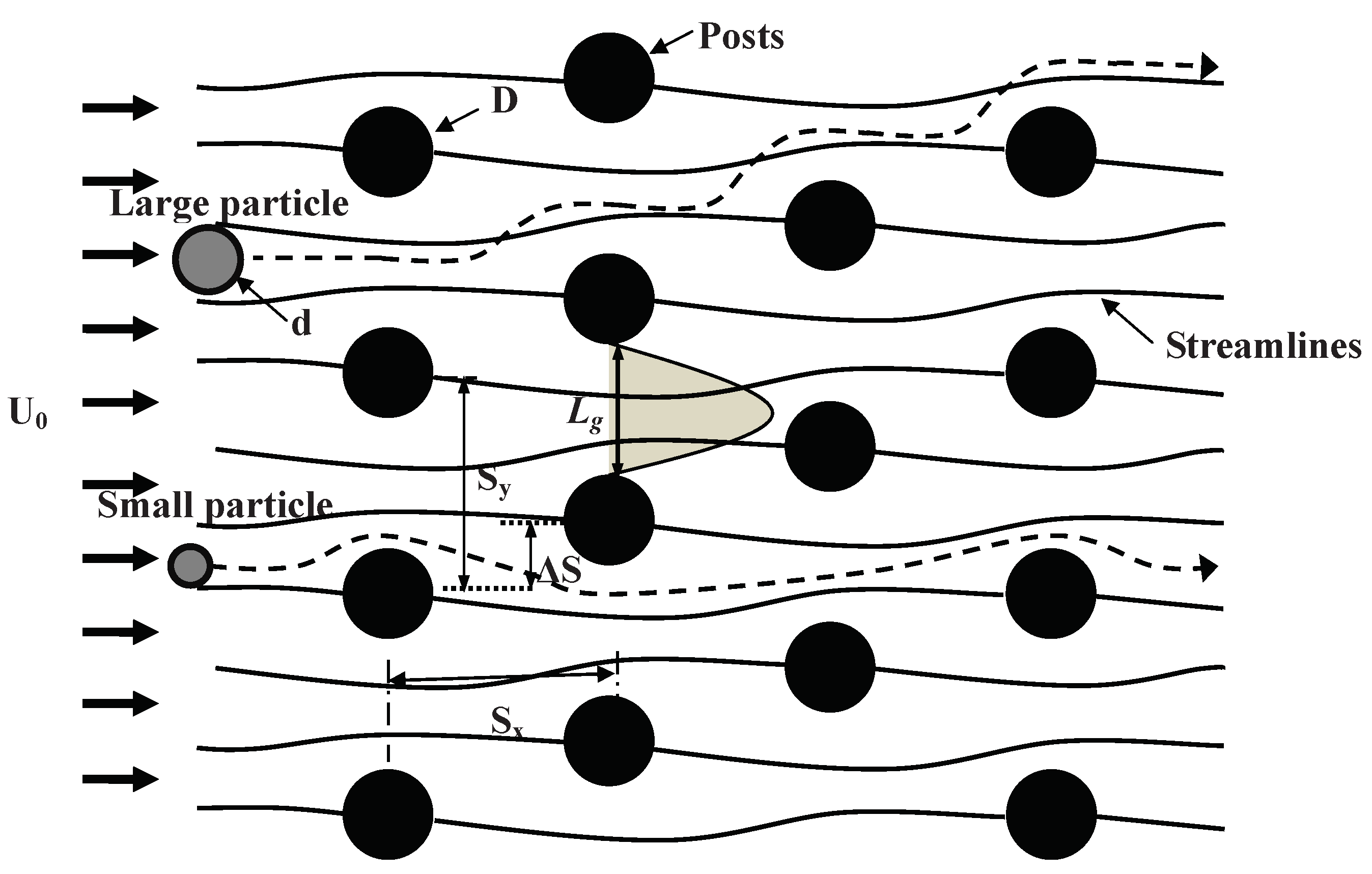
The separation of particles is an important process in the medical laboratories and biomedical industries. Some traditional separation technologies have been developed for centuries, such as filtration, centrifugation, chromatography, and electrophoresis [1]. In recent decades, with the rapid development of micro-electromechanical systems (MEMS), several continuous flow separation methods have been proposed in microfluidic devices. Huang [2] proposed a size-based continuous separation technique, termed as “deterministic lateral displacement” (referred to as DLD). A schematic diagram of the DLD device is shown in Figure 1. The DLD device is mainly composed of an ordered array of obstacles such as cylindrical posts. The array has a fixed lateral shift between the neighboring columns. Small particles are able to largely follow the undisturbed streamlines through the array along a zigzag path (referred to as zigzag mode), whereas large particles travel across the flow lane or the “separation” streamlines which go through the stagnation points of the flow past the posts due to the interaction with the posts, being laterally displaced (referred to as lateral-displacement mode), as shown in Figure 1.
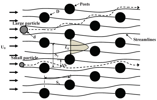
Figure 1.
Schematic diagram of the deterministic lateral displacement (DLD) device with the periodicity of 3, illustrating the particle separation as a result of different motion modes for large and small particles. There are three flow lanes between vertical neighboring posts separated by the streamlines through the post-stagnation points for the periodicity of 3. Reproduced from Davis [6].
The DLD separation technique is attractive due to its advantages of easy implementation, fast sorting speed, and high size-resolution, and has been widely used to separate bioparticles [3,4,5], such as separation of the blood cell components [6,7] and separation of living parasites [8] and circulating tumor cells [9] from blood.
The critical particle diameter for the separation or two motion modes is a key fundamental issue for the DLD separation technique, and has been investigated theoretically, numerically, and experimentally. Inglis [10] proposed a theoretical model for the critical diameter of rigid particles, which was assumed to be equal to twice the width of the first flow lane above the post surface, as shown in Figure 1. Although the theory generally underestimates the critical diameters [10], it has been widely used as a convenient tool to predict the critical separation size by using the single-phase flow field without solving the particle–fluid interactions [11,12,13]. The effects of the post shape, the fluid property, and the particle property on the DLD separation performance have been receiving much attention. Regarding the post shape, the triangular post [11,12], the diamond and airfoil post [14], the I-shaped post [15], and the airfoil post with various angle-of-attacks [13] have been investigated. Regarding the fluid property, D’Avino [16] investigated the effects of the shear-thinning property of the non-Newtonian fluids on the particle critical diameter with a distributed-Lagrange-multiplier-based fictitious domain method and observed that fluid shear-thinning contributed to decrease the critical particle diameter compared to the Newtonian case by altering the flow field between the posts. Li [17] further demonstrated experimentally that the critical diameter was affected by not only shear-thinning but also elastic effects of the viscoelastic medium. The fluid inertial effects on the separation performance were studied by Lubbersen [18] and Dincau [19]. Regarding the particle property, Beech [20] experimentally examined the effects of the deformation of erythrocytes in the DLD device, and found that the motion mode could be changed from the lateral displacement to the zigzag, as the particle deformability was increased. The effects of the particle flexibility on the separation has also been investigated by two-dimensional direct numerical simulations [21,22,23,24,25] and three-dimensional simulations [26,27]. The reader is referred to McGrath [3], Salafi [4], and Hochstetter [5] for a nice review of the progress in the DLD field.
Despite wide applications of the DLD technique, there are still various fundamental issues that have not been well resolved [5]. A full understanding of particle mode behavior remains elusive, even for simple rigid spherical particles with cylindrical posts, as pointed out by Hochstetter [5]. There exists some discrepancy in the critical particle size between different experiments for rigid spherical particles with cylindrical posts [5]. The theory underestimates the critical size measured in the experiments, as mentioned earlier, and the reason should be related to the short-range interaction between the particle and the post. Although the particle motion in DLD has been investigated with various numerical methods, such as the immersed boundary lattice Boltzmann method [24,26,28], immersed boundary (or similarly fictitious domain) finite difference method [21,22], dissipative particle dynamics [23,27], and boundary integral method [25], the effect of the lubrication force has not been examined, to the best of our knowledge. In addition, most previous numerical simulations are two-dimensional, with very limited three-dimensional simulations [26,27]. In the present study, we intend to develop a novel and efficient three-dimensional fictitious domain method specified for the DLD problem and then examine the effect of the lubrication force saturation on the motion mode of a non-colloidal spherical particle in the cylindrical post array. Our results show that the lubrication force saturation is important to the particle critical separation size, and a larger saturation distance generally makes the particle more prone to the lateral displacement mode. The rest of the paper is organized as follows. In Section 2, we present the numerical method, and the mesh convergence test for the single-phase flow in DLD is performed. In Section 3, we report and discuss the results on the effect of the lubrication force saturation. Finally, we summarize the main contributions of the present study in Section 4.
2. Numerical Model
2.1. Flow Model
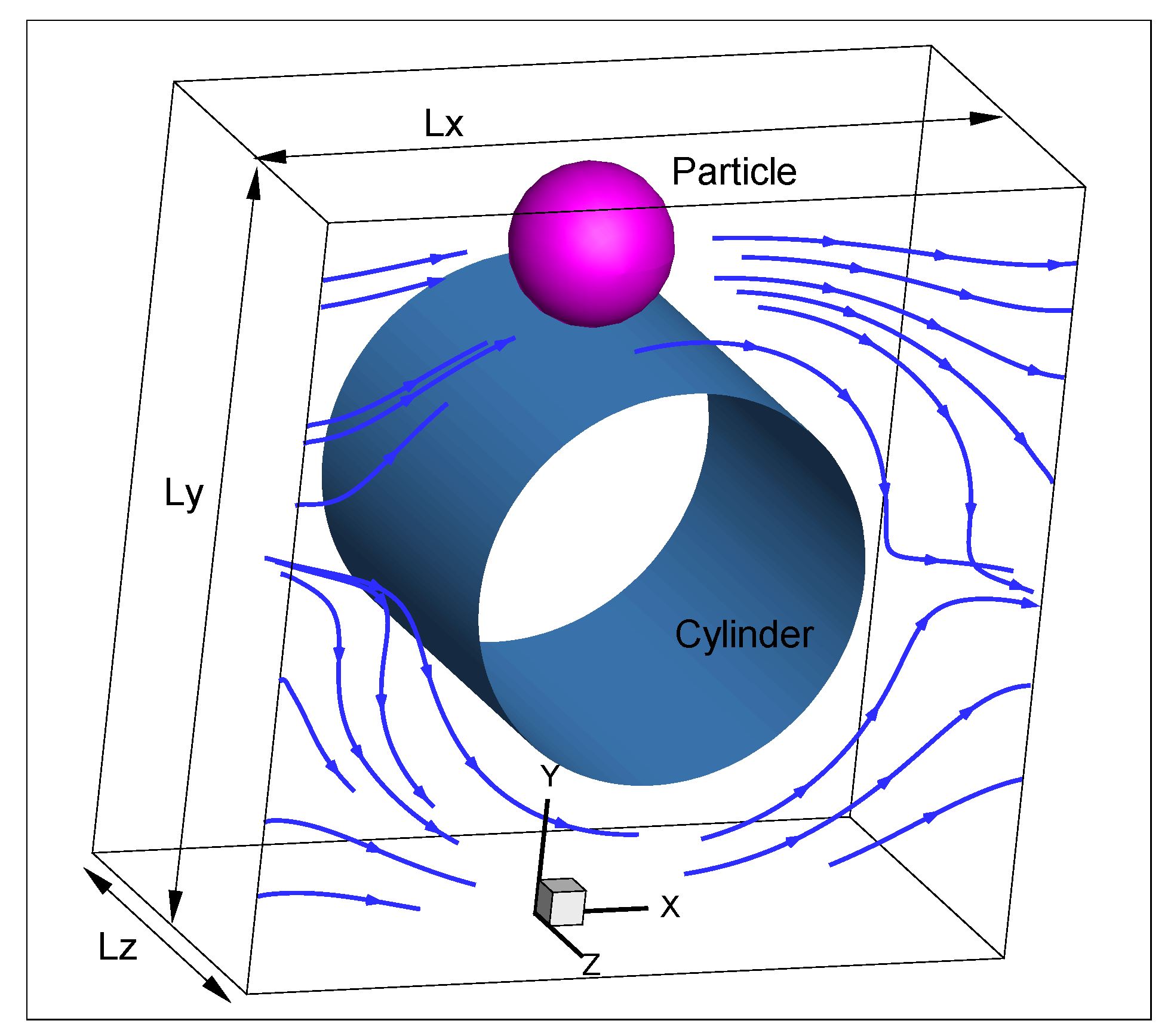
We have developed the direct-forcing fictitious domain (DF/FD) method [29] for the direct numerical simulation of particle-laden flows, based on the modification of the original distributed-Lagrange-multiplier-based FD method of Glowinski [30]. The key idea of the FD method is to fill the interior domain of particles with fictitious fluids, and distribute a pseudo-body force (i.e., distributed Lagrange multiplier) over the solid region to enforce the rigid-body constraints [30]. Our FD method has been applied to the motion mode of a flexible particle in a two-dimensional DLD device [22] and a wide range of particle-laden flows (e.g., [31,32,33,34]). However, it is not possible to apply our FD code to a three-dimensional DLD geometry with a great many number of posts and inlet–outlet boundaries due to huge computational costs. Thus, following Krüger [26] and Henry [27], we adopt a DLD cell with the periodic boundary condition in the lateral (y) direction and a shifted periodic boundary condition in the streamwise (x) direction, as shown in Figure 2. The no-slip wall boundary condition is imposed in the spanwise (z) direction, since we plan to examine the spanwise spatial constraint effect on the motion of the bioparticle in the DLD device [35] in the future. A pressure gradient is imposed in the streamwise direction to maintain a constant fluid mean velocity . The size of the computational domain (i.e., DLD cell) is . The cylinder with the diameter of D is located at the center of the cell. In the present study, we set , and , so that the gap distance between vertical neighboring posts (i.e., in Figure 1) is . For a row shift of , the shifted periodic boundary condition implies that
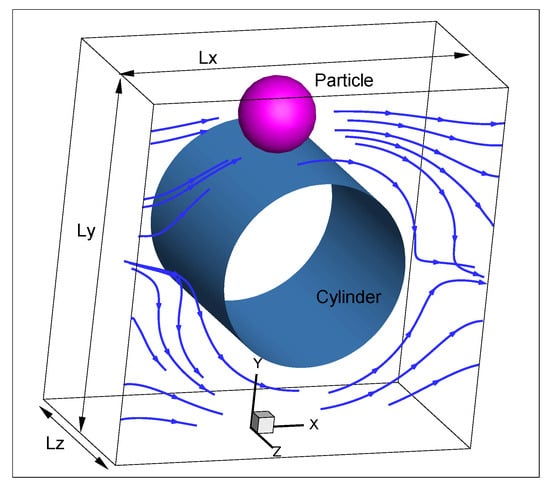
Figure 2.
Flow model of a DLD cell containing a stationary cylinder and a moving particle. The periodic boundary condition is imposed in the lateral (y) direction and the streamwise (x) direction with a shifted distance.
The row shift fraction is defined as , and the periodicity of the DLD system is when is an integer.
Two significant modifications of our previous FD method are required. One is on the fast solver for the pressure Poison equation specified for the shifted periodic boundary condition, and the other is that our previous half-staggered finite-difference scheme was found unstable for this problem, and so the conventional staggered finite-difference scheme is then adopted. In the following, we describe our modified FD method for the motion of one particle in the DLD cell.
2.2. Fictitious Domain Method
Suppose that the particle density, volume, moment of inertia, translational velocity, and angular velocity are , , , , and , respectively. The viscosity and density of the fluid are and , respectively. Let represent the solid domain and the entire computational domain containing both solid and fluid regions. We introduce the following characteristic scales for the non-dimensionalization: the cylinder diameter D for length, the fluid mean velocity for velocity, for time, for pressure, and for the pseudo-body force. Then, the dimensionless FD formulation for the incompressible fluid can be written as
where , p, , represent the fluid velocity, pressure, pseudo-body force, and position vector with respect to the mass center of the particle, respectively. is the particle to fluid density ratio, the Reynolds number defined by , the Froude number defined by , with being the gravitational acceleration, the dimensionless particle volume define by , and the dimensionless moment of inertia defined by .
A fractional-step temporal scheme is used to decouple the system (2)–(6) into the following two sub-problems:
Fluid sub-problem for and p:
We will introduce the solution of the fluid sub-problem later.
Particle sub-problem for , , and :
Then, the pseudo-body forces defined at the Lagrangian nodes are updated from
Finally, the fluid velocities at the Eulerian nodes are corrected as follows:
In the above manipulations, a discrete -function in the form of a tri-linear function is used to transfer quantities between the Eulerian and Lagrangian nodes.
The no-slip boundary condition on the cylinder is enforced by introducing another pseudo-body force distributed on the cylinder surface.
2.3. Solution of Fluid Sub-Problem
- Velocity Helmholtz equationwhere .
- Pressure Poison equation
- Velocity and pressure correction
The velocity Helmholtz Equation (13) is solved with the Douglas Gunn alternating-direction-implicit (ADI) scheme [36]:
In the above equations, , , and represent the second-order derivative in the x, y, and z directions, respectively. In the absence of , the Douglas Gunn scheme above is second-order accurate and unconditionally stable.
A homogeneous grid is used. For our previous FD method, a half-staggered grid was employed, which means that the velocity components are collocated but the pressure nodes are staggered with the velocity nodes. Somehow this scheme was found unstable for the present problem, and thus we adopt the fully staggered grid. The velocity derivatives in the convection and diffusion terms are discretized with a second-order central difference scheme.
The most time-consuming step for the incompressible flow is the solution of the pressure Poison Equation (14). Here, we develop a combined FFT and tri-diagonal-system fast solver for the present problem. The pressure is defined at the cell center and the discretized pressure equation at the pressure node can be written as follows:
for . Here M, N, and L represent the cell numbers of the computational domain in the x, y, and z directions, respectively. Since the pressure is periodic in the y direction and its normal gradient on the side wall is zero, we perform an FFT in the y direction and a fast cosine transformation in the spanwise (z) direction, and the pressure in the physical space can be expanded with its spectrum :
where denotes the imaginary number .
Expanding all terms in (20) with (21), one can obtain the following equation for the pressure spectrum:
which is a tri-diagonal system and holds for .
For the shifted periodic boundary condition, the equation for and needs to be treated specifically. We assume that the row shift satisfies
where h denotes the mesh size. The pressure equation in the physical space for (i.e., the first cell center node from the left) is
Then, the pressure equation in the spectral space for is
Similarly, one can derive the pressure equation in the spectral space for :
2.4. Lubrication Force Correction
Since the fictitious domain method is based on a fixed Cartesian grid, the short-range lubrication force cannot be resolved when the gap distance between the particle and the cylinder is smaller than one mesh. Thus, the lubrication force correction is needed. We denote the particle radius and the cylinder radius as a and R, respectively, and define the size ratio as , the gap distance between the particle and cylinder surfaces as , and the normalized gap distance .
The lubrication force correction has the following form:
where is the particle normal relative velocity with respect to the cylinder. is the critical gap below which the lubrication correction is activated, and in the present study we set , where h is the mesh size. is a function of the normalized gap distance . Since we cannot find the formulation of the lubrication force between a particle and a cylinder, we adopt the formulation for two spherical particles [38]:
Note that the lubrication correction is kept constant for to account for the lubrication force saturation due to the effect of the surface roughness. The lubrication force is solved implicitly. It should be noted that the lubrication force for two spherical particles is weaker than that for the particle–cylinder at the same gap distance, thus we consider our computation of the particle motion reasonably accurate, not highly accurate.
2.5. Mesh Convergence Test
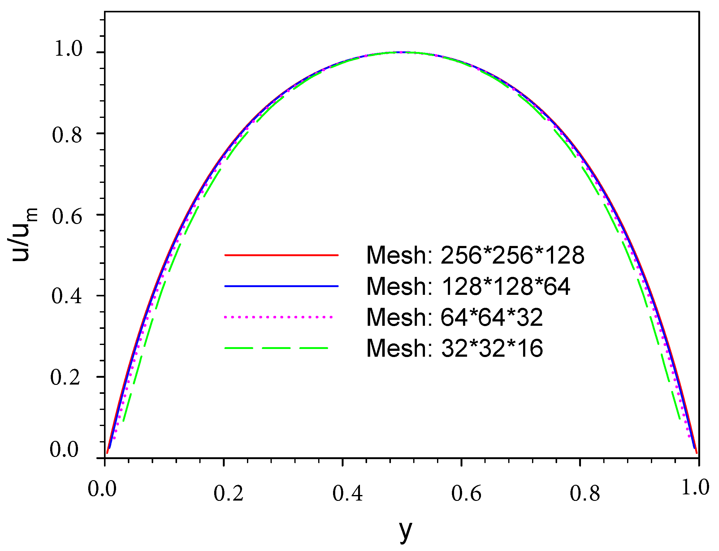
The modification of our previous FD code on the solution of the fluid field is substantial, but there are no data on DLD in literature available for rigorously validating our code. Hence, we perform a mesh convergence test for the solution of the flow in the absence of the particle, which also helps to choose a suitable mesh resolution. The computational domain size is , as mentioned earlier. The profiles of the streamwise velocity normalized with its maximum between vertical neighboring posts for the mesh numbers of , , , and are compared in Figure 3. One can see that the solution with the mesh is in excellent agreement with the one with .
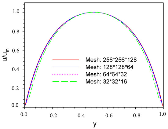
Figure 3.
Profiles of the streamwise velocity normalized with its maximum between vertical neighboring posts for the mesh numbers of , , , and .
The mesh is chosen for the simulation of the particle motion in DLD. The smallest particle diameter we consider is , which covers more than 15 meshes. Our previous works showed that this mesh resolution is sufficient for the prediction of the particle motion with reasonable accuracy for various situations [22,29,31,32,33,34]. Throughout this study, the Reynolds number based on the cylinder diameter and the fluid mean velocity is , as an approximation to the creep flow. Our test showed that further decrease in does not change the result. The time step is , which was found to be small enough for the time-step-independent particle trajectory. The particle is assumed to be non-colloidal, and thus the Brownian motion does not need to be considered. The density ratio is unity.
3. Results and Discussion
In the present study, we only consider the DLD geometries with the periodicity N = 8, 16, and 32 (i.e., the row shift fraction 0.125, 0.0625, and 0.03125), and the saturation distance of the lubrication force ranging from 0.002R to 0.01R; here R being the cylinder radius.
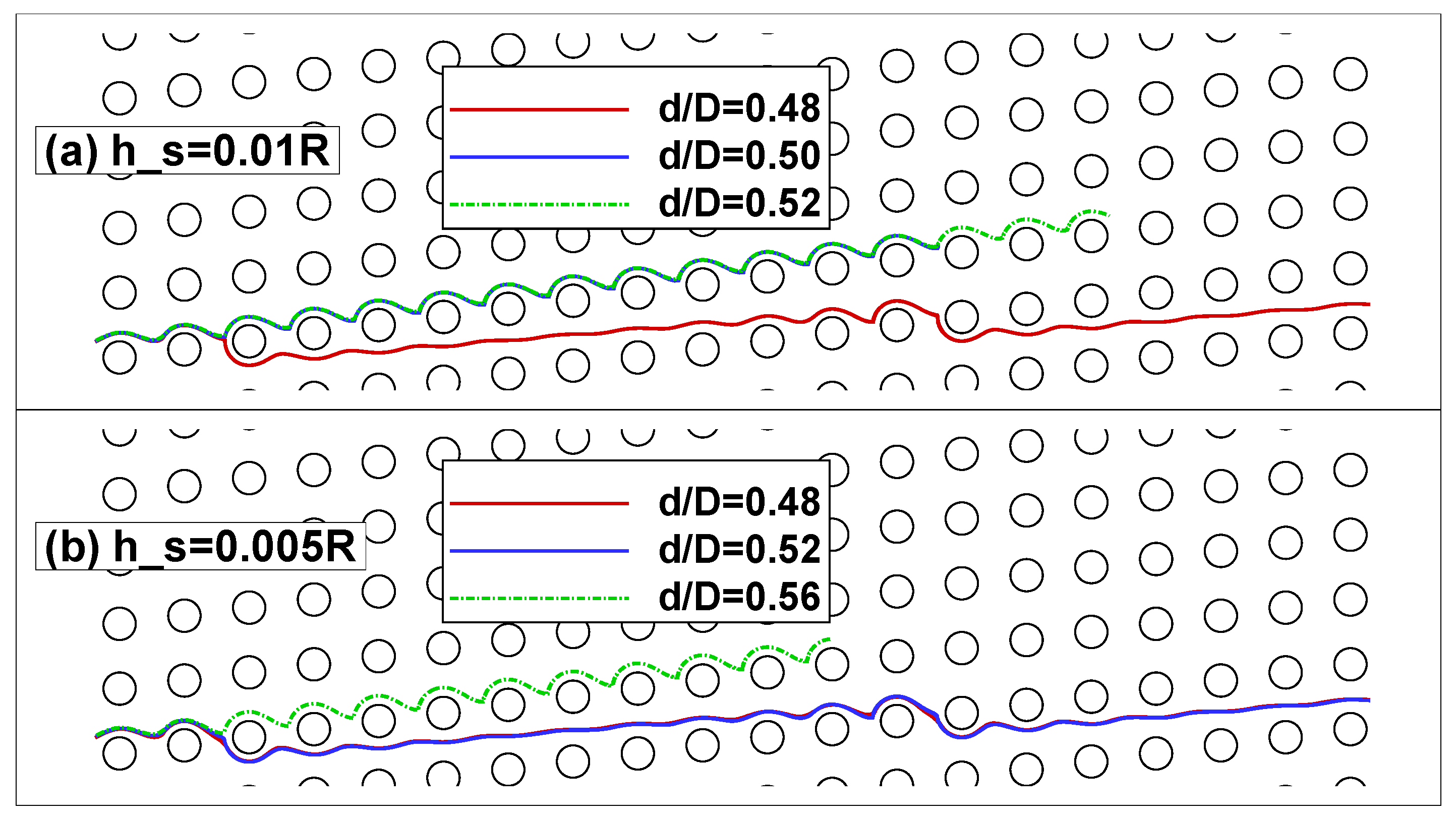
The particle trajectories for different particle sizes at and till in the DLD with the periodicity of N = 8 are plotted in Figure 4. We define the motion mode as “lateral-displacement” (referred to as LD) only if the particle keeps moving upwards along the same tilted channel, and otherwise as “zigzag mode”. Figure 4 shows that at the motion mode undergoes a transition from zigzag for the particle of to LD for the particle of . By contrast, the transition from zigzag to LD takes place from to for , as shown in Figure 4b. The particle of moves with the LD mode for , but moves with the zigzag mode for .
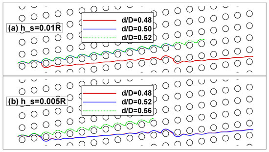
Figure 4.
Particle trajectories for different particle sizes at (a) and (b) till in the DLD with the periodicity of N = 8.
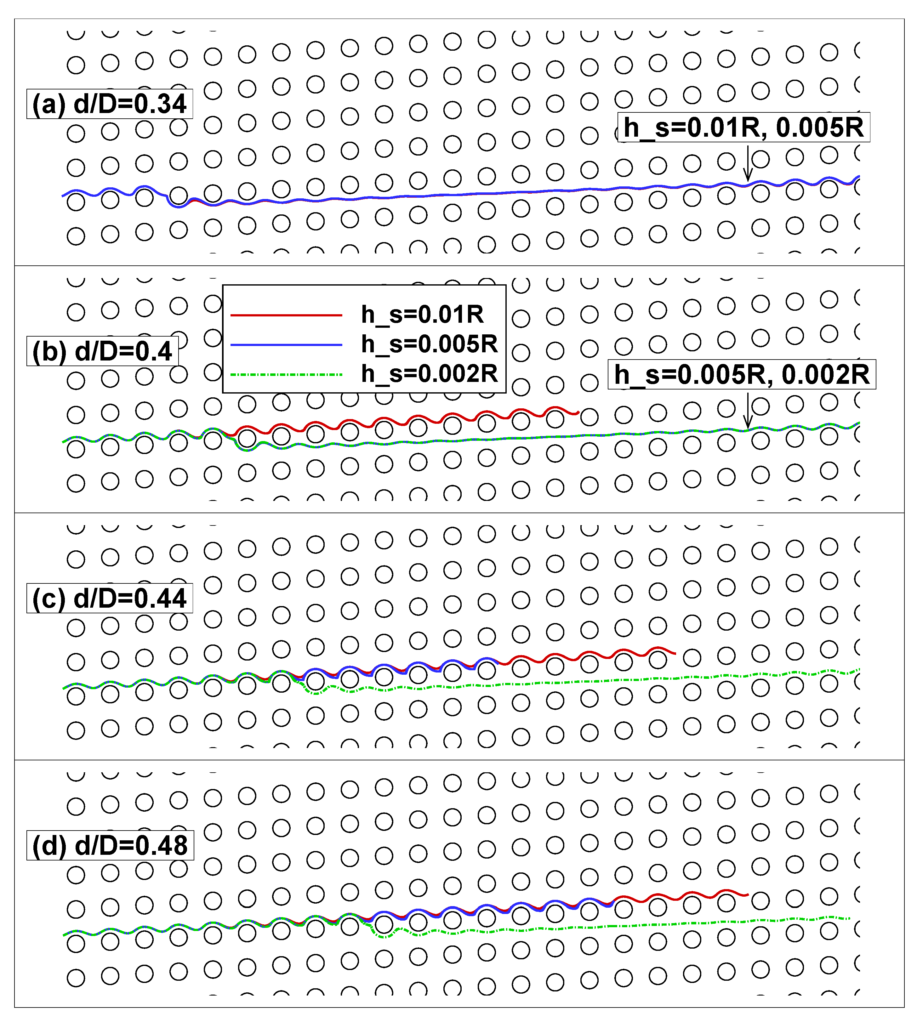
Figure 5 shows the particle trajectories for ,,, and at different till in the DLD with the periodicity of N = 16. We see that the particle of experiences a mode transition from zigzag at to LD at in Figure 5b, and the particles of and experience such transition from to in Figure 5c,d. Therefore, the effect of the lubrication force saturation on the motion mode is significant. The lubrication force serves as a repulsive force when the particle approaches the cylinder and as an attractive force when the particle moves away from the cylinder. From our results, the lubrication force tends to make the particle more prone to the zigzag mode, consistent with the observation that the experimental critical particle diameter is larger than the theoretical prediction (i.e., twice the first flow lane width) [5,10]. As the saturation distance increases, the effect of the lubrication force decreases, resulting in the transition from zigzag to LD, as observed above.
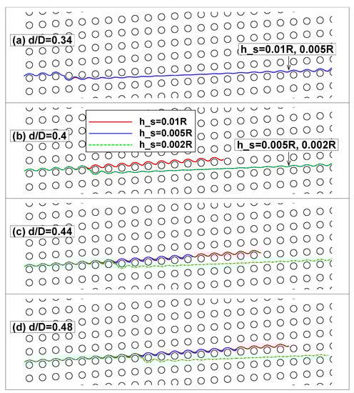
Figure 5.
Particle trajectories for (a) ; (b) ; (c) ; and (d) at different lubrication force saturation distances till in the DLD with the periodicity of N = 16.
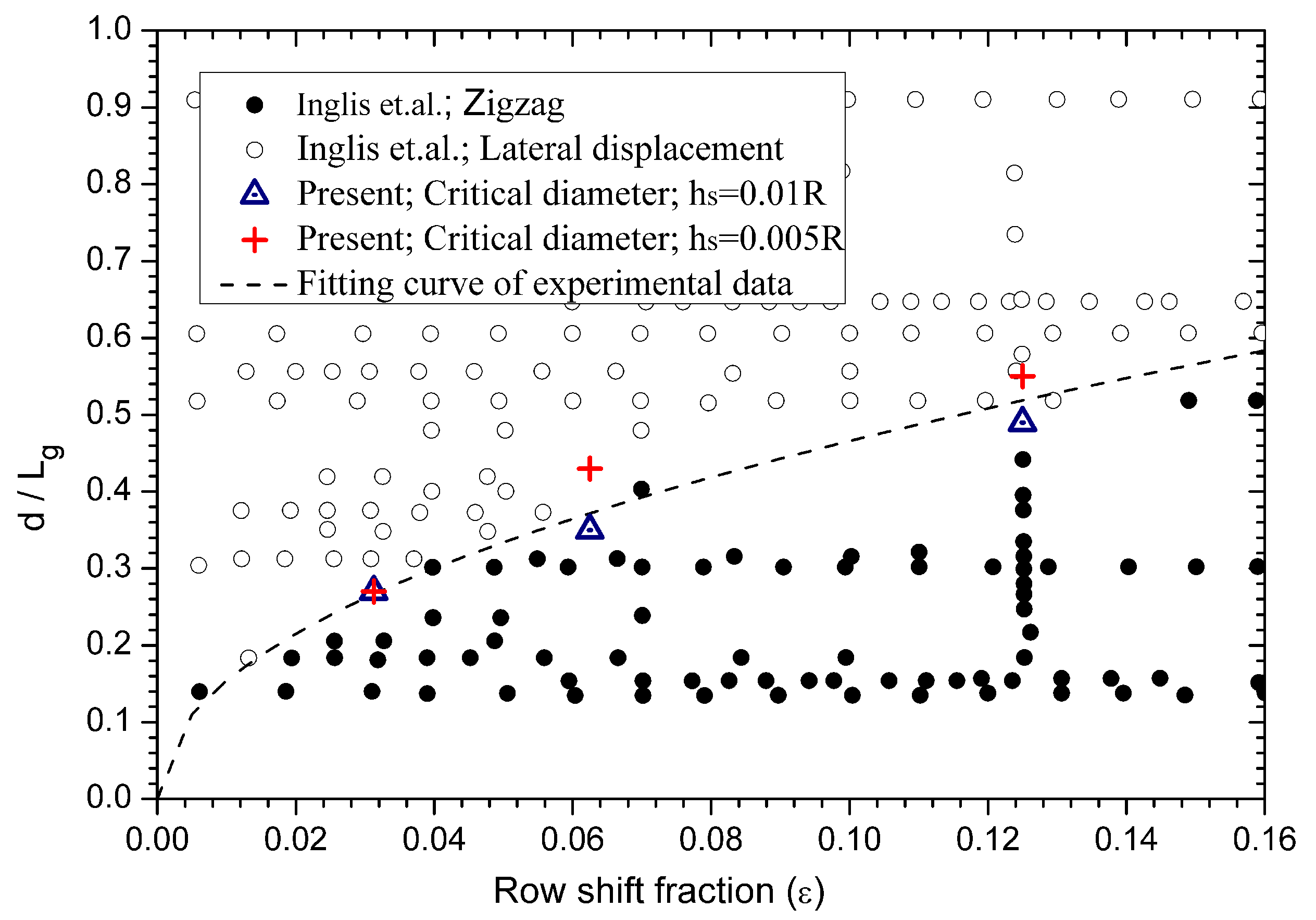
We search for the critical particle diameter of two motion modes with the smallest variation of the particle diameter being . For example, for and N = 8 (i.e., 0.125), the mode transition takes place from to , as shown in Figure 4a, and then we take the critical diameter as for this case. From our simulations, , 0.35, and 0.27 for N = 8, 16, and 32 at , respectively, and , 0.43, and 0.27 for N = 8, 16, and 32 at , respectively. The critical diameter is commonly normalized with the gap distance between vertical neighboring posts (see Figure 1). Here, , since . Our results on the critical diameter are compared to the experiments of Inglis [10] in Figure 6, and good agreement between the two results can be observed. may be regarded as the surface roughness in the experiments, and the surface roughness of may be reasonable for micro-posts in lab.
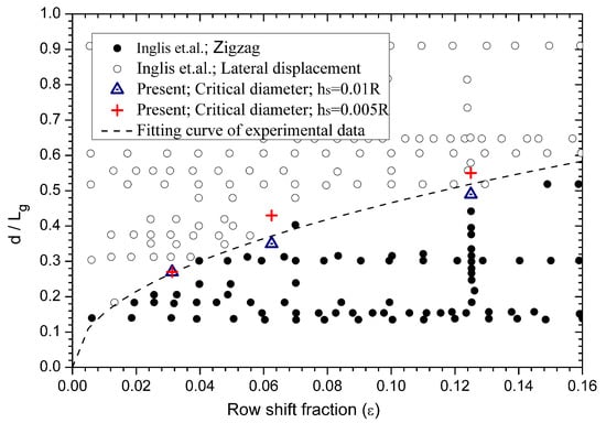
Figure 6.
Comparison between our numerical results and the experiments of Inglis [10] on the critical particle diameter. The experimental fitting is .
From Figure 6, the critical diameter is higher at a lower for N = 8 and 16, as observed in Figure 4 and Figure 5; however, they are the same at and for N = 32. Through inspecting our simulation data for the particle of (i.e., the smallest particle moving with the LD mode for both ) at and N = 32, the smallest gap distance between the particle and the cylinder is around , which is beyond the critical distance () to activate the lubrication force saturation. Thus, the particle motion is not affected by setting of and .
For a larger row shift fraction (i.e., smaller periodicity N), the particle critical diameter is larger, and the short-range hydrodynamic interaction between the particle and the cylinder is stronger; thus, generally, we expect a stronger effect of the lubrication force saturation on the particle motion mode, as evidenced by scattered experimental data on the critical diameter at large row shift fractions [5,10]. The effect of the lubrication force saturation due to the surface roughness may be an important reason for the discrepancy between the critical diameters of different groups, as shown in Hochstetter [5].
4. Conclusions
We have developed an efficient three-dimensional FD method for direct numerical simulation of the particle motion in the DLD device, based on considerable modification of our previous FD method. A combination of the FFT and a tri-diagonal solver is developed to efficiently solve the pressure Poisson equation for a DLD unit with a shifted periodic boundary condition in the streamwise direction. The half-staggered grid is changed to the fully staggered grid. Our results indicate that the lubrication force saturation is important to the particle critical separation size, and a smaller saturation distance generally makes the particle more prone to the zigzag mode.
Author Contributions
Conceptualization, Z.Y. and Y.Y.; methodology, Z.Y.; software, Z.Y.; validation, Z.Y. and Y.Y.; formal analysis, Z.Y. and Y.Y.; investigation, Z.Y. and Y.Y.; resources, Z.Y.; data curation, Z.Y. and Y.Y.; writing—original draft preparation, Z.Y. and Y.Y.; writing—review and editing, Z.Y. and J.L.; visualization, Z.Y. and Y.Y.; supervision, Z.Y.; project administration, Z.Y. and J.L.; funding acquisition, Z.Y. and J.L. All authors have read and agreed to the published version of the manuscript.
Funding
This research was funded by the National Natural Science Foundation of China (Grant Nos. 12072319 and 12132015).
Data Availability Statement
The data presented in this study are available on request from the corresponding author.
Conflicts of Interest
The authors declare no conflict of interest.
References
- Pamme, N. Continuous flow separations in microfluidic devices. Lab Chip 2007, 7, 1644–1659. [Google Scholar] [CrossRef] [PubMed]
- Huang, L.R.; Cox, E.C.; Austin, R.H.; Sturm, J.C. Continuous particle separation through deterministic lateral displacement. Science 2004, 304, 987–990. [Google Scholar] [CrossRef] [PubMed]
- McGrath, J.; Jimenez, M.; Bridle, H. Deterministic lateral displacement for particle separation: A review. Lab Chip 2014, 14, 4139–4158. [Google Scholar] [CrossRef] [PubMed] [Green Version]
- Salafi, T.; Zhang, Y.; Zhang, Y. A review on deterministic lateral displacement for particle separation and detection. Nano-Micro Lett. 2019, 11, 77. [Google Scholar] [CrossRef] [Green Version]
- Hochstetter, A.; Vernekar, R.; Austin, R.H.; Becker, H.; Beech, J.P.; Fedosov, D.A.; Gompper, G.; Kim, S.C.; Smith, J.T.; Stolovitzky, G.; et al. Deterministic lateral displacement: Challenges and perspectives. ACS Nano 2020, 14, 10784–10795. [Google Scholar] [CrossRef]
- Davis, J.A.; Inglis, D.W.; Morton, K.J.; Lawrence, D.A.; Huang, L.R.; Chou, S.Y.; Sturm, J.C.; Austin, R.H. Deterministic hydrodynamics: Taking blood apart. Proc. Natl. Acad. Sci. USA 2006, 103, 14779–14784. [Google Scholar] [CrossRef] [Green Version]
- Inglis, D.W.; Morton, K.J.; Davis, J.A.; Zieziulewicz, T.J.; Lawrence, D.A.; Austin, R.H.; Sturm, J.C. Microfluidic device for label-free measurement of platelet activation. Lab Chip 2008, 8, 925–931. [Google Scholar] [CrossRef]
- Holm, S.H.; Beech, J.P.; Barrett, M.P.; Tegenfeldt, J.O. Separation of parasites from human blood using deterministic lateral displacement. Lab Chip 2011, 11, 1326–1332. [Google Scholar] [CrossRef]
- Loutherback, K.; D’Silva, J.; Liu, L.; Wu, A.; Austin, R.H.; Sturm, J.C. Deterministic separation of cancer cells from blood at 10 mL/min. AIP Adv. 2012, 2, 042107. [Google Scholar] [CrossRef] [Green Version]
- Inglis, D.W.; Davis, J.A.; Austin, R.H.; Sturm, J.C. Critical particle size for fractionation by deterministic lateral displacement. Lab Chip 2006, 6, 655–658. [Google Scholar] [CrossRef]
- Loutherback, K.; Puchalla, J.; Austin, R.H.; Sturm, J.C. Deterministic microfluidic ratchet. Phys. Rev. Lett. 2009, 102, 045301. [Google Scholar] [CrossRef] [PubMed] [Green Version]
- Loutherback, K.; Chou, K.S.; Newman, J.; Puchalla, J.; Austin, R.H.; Sturm, J.C. Improved performance of deterministic lateral displacement arrays with triangular posts. Microfluid. Nanofluidics 2010, 9, 1143–1149. [Google Scholar] [CrossRef]
- Al-Fandi, M.; Al-Rousan, M.; Jaradat, M.A.K.; Al-Ebbini, L. New design for the separation of microorganisms using microfluidic deterministic lateral displacement. Robot. Comput.-Integr. Manuf. 2011, 27, 237–244. [Google Scholar] [CrossRef]
- Ahasan, K.; Landry, C.M.; Chen, X.; Kim, J.H. Effect of angle-of-attacks on deterministic lateral displacement (dld) with symmetric airfoil pillars. Biomed. Microdevices 2020, 22, 42. [Google Scholar] [CrossRef] [PubMed]
- Zeming, K.K.; Ranjan, S.; Zhang, Y. Rotational separation of non-spherical bioparticles using i-shaped pillar arrays in a microfluidic device. Nat. Commun. 2013, 4, 1625. [Google Scholar] [CrossRef] [PubMed] [Green Version]
- D’Avino, G. Non-newtonian deterministic lateral displacement separator: Theory and simulations. Rheol. Acta 2013, 52, 221–236. [Google Scholar] [CrossRef]
- Li, Y.; Zhang, H.; Li, Y.; Li, X.; Wu, J.; Qian, S.; Li, F. Dynamic Control of Particle Separation in Deterministic Lateral Displacement Separator with Viscoelastic Fluids. Sci. Rep. 2018, 8, 3618. [Google Scholar] [CrossRef] [PubMed]
- Lubbersen, Y.S.; Schutyser, M.A.I.; Boom, R.M. Suspension separation with deterministic ratchets at moderate Reynolds numbers. Chem. Eng. Sci. 2012, 73, 314–320. [Google Scholar] [CrossRef]
- Dincau, B.M.; Aghilinejad, A.; Hammersley, T.; Chen, X.; Kim, J.H. Deterministic lateral displacement (DLD) in the high Reynolds number regime: High-throughput and dynamic separation characteristics. Microfluid. Nanofluidics 2018, 22, 59. [Google Scholar] [CrossRef]
- Beech, J.P.; Holm, S.H.; Adolfsson, K.; Tegenfeldt, J.O. Sorting cells by size, shape and deformability. Lab Chip 2012, 12, 1048–1051. [Google Scholar] [CrossRef] [Green Version]
- Quek, R.; Le, D.V.; Chiam, K.H. Separation of deformable particles in deterministic lateral displacement devices. Phys. Rev. E 2011, 83, 056301. [Google Scholar] [CrossRef] [PubMed] [Green Version]
- Ye, S.; Shao, X.; Yu, Z.; Yu, W. Effects of the particle deformability on the critical separation diameter in the deterministic lateral displacement device. J. Fluid Mech. 2014, 743, 60–74. [Google Scholar] [CrossRef]
- Zhang, Z.; Henry, E.; Gompper, G.; Fedosov, D.A. Behavior of rigid and deformable particles in deterministic lateral displacement devices with different post shapes. J. Chem. Phys. 2015, 143, 243145. [Google Scholar] [CrossRef] [PubMed] [Green Version]
- Wei, Q.; Xu, Y.Q.; Tang, X.Y.; Tian, F.B. An IB-LBM study of continuous cell sorting in deterministic lateral displacement arrays. Acta Mech. Sin. 2016, 32, 1023–1030. [Google Scholar] [CrossRef]
- Kabacaoğlu, G.; Biros, G. Sorting same-size red blood cells in deep deterministic lateral displacement devices. J. Fluid Mech. 2019, 859, 433–475. [Google Scholar] [CrossRef] [Green Version]
- Krüger, T.; Holmes, D.; Coveney, P.V. Deformability-based red blood cell separation in deterministic lateral displacement devices-A simulation study. Biomicrofluidics 2014, 8, 054114. [Google Scholar] [CrossRef] [Green Version]
- Henry, E.; Holm, S.H.; Zhang, Z.; Beech, J.P.; Tegenfeldt, J.O.; Fedosov, D.A.; Gompper, G. Sorting cells by their dynamical properties. Sci. Rep. 2016, 6, 34375. [Google Scholar] [CrossRef] [Green Version]
- Vernekar, R.; Krüger, T. Breakdown of deterministic lateral displacement efficiency for non-dilute suspensions: A numerical study. Med. Eng. Phys. 2015, 37, 845–854. [Google Scholar] [CrossRef] [Green Version]
- Yu, Z.; Shao, X. A direct-forcing fictitious domain method for particulate flows. J. Comput. Phys. 2007, 227, 292–314. [Google Scholar] [CrossRef]
- Glowinski, R.; Pan, T.W.; Hesla, T.I.; Joseph, D.D. A distributed Lagrange multiplier/fictitious domain method for particulate flows. Int. J. Multiph. Flow 1999, 25, 755–794. [Google Scholar] [CrossRef]
- Yu, Z.; Xia, Y.; Guo, Y.; Lin, J. Modulation of turbulence intensity by heavy finite-size particles in upward channel flow. J. Fluid Mech. 2021, 913, A3. [Google Scholar] [CrossRef]
- Yu, Z.; Wang, P.; Lin, J.; Hu, H.H. Equilibrium positions of the elasto-inertial particle migration in rectangular channel flow of Oldroyd-B viscoelastic fluids. J. Fluid Mech. 2019, 868, 316–340. [Google Scholar] [CrossRef]
- Yu, Z.; Wachs, A.; Peysson, Y. Numerical simulation of particle sedimentation in shear-thinning fluids with a fictitious domain method. J. Non-Newton. Fluid Mech. 2006, 136, 126–139. [Google Scholar] [CrossRef]
- Yu, Z.; Wachs, A. A fictitious domain method for dynamic simulation of particle sedimentation in Bingham fluids. J. Non-Newton. Fluid Mech. 2007, 145, 78–91. [Google Scholar] [CrossRef]
- Holm, S.H.; Beech, J.P.; Barrett, M.P.; Tegenfeldt, J.O. Simplifying microfluidic separation devices towards field-detection of blood parasites. Anal. Methods 2016, 8, 3291–3300. [Google Scholar] [CrossRef] [Green Version]
- Douglas, J.; Gunn, J.E. A general formulation of alternating direction methods. NumèRische MathèMatik 1964, 6, 428–453. [Google Scholar] [CrossRef]
- Press, W.H.; Teukolsky, S.A.; Vetterling, W.T.; Flannery, B.P. Numerical Recipes: The Art of Scientific Computing, 3rd ed.; Cambridge University Press: Cambridge, UK, 2007. [Google Scholar]
- Kim, S.; Karrila, S.J. Microhydrodynamics: Principles and Selected Applications; Butterworth-Heinemann: Stoneham, MA, USA, 1991. [Google Scholar]
Publisher’s Note: MDPI stays neutral with regard to jurisdictional claims in published maps and institutional affiliations. |
© 2022 by the authors. Licensee MDPI, Basel, Switzerland. This article is an open access article distributed under the terms and conditions of the Creative Commons Attribution (CC BY) license (https://creativecommons.org/licenses/by/4.0/).