Article

Design and Optimization of a Boat-Bottom-Shaped Transplanting Device for Sweet Potato (Ipomoea batatas) with Low Seedling Damage Rate

1
College of Mechanical and Electrical Engineering, Qingdao Agricultural University, Qingdao 266109, China
2
College of Mechanical and Electrical Engineering, Hainan University, Haikou 570228, China
*
Author to whom correspondence should be addressed.
Appl. Sci. 2022, 12(6), 2817; https://doi.org/10.3390/app12062817
Submission received: 28 January 2022 / Revised: 5 March 2022 / Accepted: 7 March 2022 / Published: 9 March 2022
(This article belongs to the Section Agricultural Science and Technology)

Abstract

:
A transplanting manipulator and a transplanting conveyance device were devised to address the problems with current sweet potato transplanters, which cannot properly finish boat-bottom-shaped transplanting and have a high seedling damage rate. The ground wheel transmits power to the two devices in a specific transmission ratio to ensure their synchronous movement and avoid accumulated deviations. We selected the transplanting manipulator’s parameter combination that satisfies the optimal transplanting trajectory by the VB program. To avoid damage to the seedlings during clamping, the clamping force is only provided by the spring through the structural design. Combined with the agronomic requirements of boat-bottom-shaped transplanting and the characteristics of soil resistance during the transplanting process, the transplanting depth and crank rotation speed were selected as test factors. The qualified rates of node depth in the seedling middle (QRNDSM), the qualified rates of seedling root depth (QRSRD), and the qualified rates of stalk length into the soil (QRSLS) were established, and Design-Expert was used for the quadratic regression and orthogonal combination tests to optimize the factors. The results of the verification tests reveal that when the transplanting depth is in the range of 45.56 to 58.26 mm and the crank rotation speed is in the range of 39.39 to 43.45 rpm, the maximum QRNDSM is 94.91%, the maximum QRSRD is 95.42%, and the maximum QRSLS is 94.93%, which satisfies the industry standards. Research into sweet potato transplanting can benefit from this work, especially in the direction of sweet potato boat-bottom-shaped transplanting.

1. Introduction

Sweet potato (Ipomoea batatas) as a raw material for industrial starch is a high-quality anti-cancer and health food [1,2,3,4]. The massive demand for sweet potato in nations all over the world contrasts sharply with the fall in the sweet potato farming labor force. As a result, the mechanization of sweet potato transplanting is the unavoidable solution to this problem [5,6,7]. There are several methods for transplanting sweet potato, with boat-bottom transplanting being the most advantageous. Field test data have proven this conclusion [8,9].
The stems and leaves of naked sweet potato seedlings are entwined and show significant morphological peculiarities. Automatic seedling separation is difficult to achieve [10,11,12,13]. As a result, semi-automatic transplanting technology is used by sweet potato transplanters all over the world [14,15,16]. To address the impact of the machine’s forward speed change on the transplanting trajectory, researchers designed an appropriate transmission ratio based on the ground wheel drive to determine the inclination angle caused by the machine’s forward speed to a certain theoretical value during the transplanting process. By examining the movement trajectory and form of the sweet potato seedlings in combination with the mathematical model, Hu et al. [17] found the optimum difference interval between the rotation speed of the planting mechanism and the forward speed of the transplanter. As a result, the clip-on-chain motion trajectory was trochoid, satisfying the inclined operation of sweet potato. Zhu et al. [18] designed the goal function based on the smallest deviation between the design trajectory and the theoretical trajectory of the linkage movement according to the agronomically needed seedling trajectory. The connecting rod parameter combination is optimized so that the rice transplanting device can achieve the work of the oblique transplanting operation. In recent years, the linking mechanism has been employed in the use of transplanting machines to more precisely regulate the transplanting trajectory. Through simulation research, Zhang et al. [19] (pp. 37−50) created a sweet potato boat-bottom-shaped transplanting mechanism based on a connecting rod-type mechanism. EDEM and ADAMS simulate the transplanting device’s operation, and the effect of soil resistance on the transplanting device’s movement trajectory is investigated. According to the findings, the faster the transplanting speed, the worse the transplanting effect of sweet potato seedlings. However, no prototype was created for field testing. Researchers created a small program to study the impact of institutional parameter changes on the transplanting trajectory in order to more accurately realize the transplanting trajectory of agronomic needs. Using the human–computer interaction visualization aid program, Xu et al. [20] studied the influence of the five-bar mechanism parameters on the planter’s tilt angle and its trajectory, and found a set of parameters that matched agronomic requirements. The preceding content is primarily intended for transplanting trajectory research. The opening and closing process of the transplanting manipulator gripping and releasing the sweet potato seedlings, on the other hand, has a significant impact on the transplanter’s performance, because this process is prone to damaging the sweet potato seedlings. In practical work, it is difficult to precisely grasp the magnitude of the clamping force of the sweet potato seedlings. In order to prevent the sweet potato seedlings from being damaged by excessive clamping force, and since the seedlings cannot be removed from the conveyor belt if the clamping force is too small, researchers adopted the following methods. Chen et al. [21] and Zhuang et al. [22] measured the compressive value of the stem of sweet potato seedlings and took the average value as the magnitude of the clamping force required to clamp the sweet potato seedlings.
In particular, the above study examined the coordination between the forward speed of the sweet potato transplanter and the planting rate, the effect of the parameters of the planting mechanism on the transplanting track, and the selection of clamping force for holding sweet potato seedlings during transplanting. The above research is not enough to analyze the upturned part of the bottom shape transplanting trajectory. When the transplanting mechanism of the existing sweet potato transplanter changes the planting rate, the impact force of the clamping rod on the sweet potato seedlings will change, which increases the damage rate of the sweet potato seedlings. Sweet potato transplanting takes a long time, and the operation frequency is high. The vibration of the transplanter causes the conveyor belt to slide longitudinally and laterally along the drive shaft. After repeated transplantation, there will be cumulative deviations, which will affect the transplantation effect.
To address the boat-bottom-shaped transplanting of sweet potato seedlings and lower the rate of seedling damage during the transplanting process, the objectives of this paper were to (1) realize the synchronous movement of the transplanting conveyor belt and the transplanting manipulator, to avoid accumulated deviation after long-term operation; (2) obtain the parameter combination that the transplanting manipulator can satisfy the bottom-shaped transplanting trajectory; and (3) solve the damage to the sweet potato seedlings caused by the change in the impact force during the clamping due to the change in the transplanting speed.

2. Structural Design

2.1. Agronomic Requirements for Boat-Bottom-Shaped Transplanting

The schematic diagram of boat-bottom-shaped insertion method transplanting is shown in Figure 1. The boat-bottom-shaped insertion method means that the sweet potato plants curve downward in the soil and all the leaves show above the ridge, and the sweet potato stalk in the soil is boat-bottom-shaped. The agronomic requirements for boat-bottom-shaped sweet potato transplanting are as follows: (a) 40–60 mm depth of the seedling stalk’s middle part immersed in soil, (b) 20–30 mm depth of the seedling stalk’s root end immersed in soil, and (c) 180–220 mm length of the stalk immersed in soil [23].

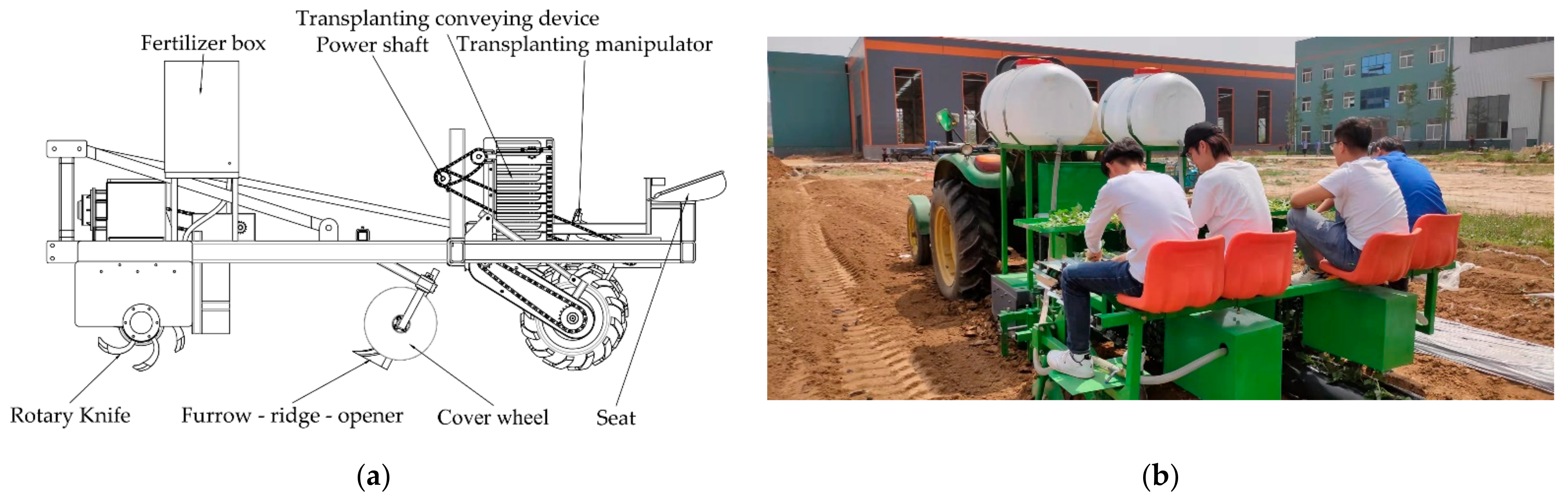
2.2. Overall Structure and Working Principle

In order to realize the boat-bottom-shaped transplanting, we designed a transplanting device as shown in Figure 2, which includes a transplanting manipulator and a transplanting conveying device. The transplanting manipulator includes a four-bar mechanism, cams, springs, levers, etc., and the transplanting conveying device includes rubber clamps, conveying unit trays, large baffles, small baffles, conveyor belts, etc.
As shown in Figure 2b, the seedlings are fixed on the platform unit and the fixed position is about 2 cm away from the root end of the seedlings, and then the seedlings are transported along with the transplanting conveyor rotation. As shown in Figure 2c, the rotation of the crank drives the movement of the entire transplanting manipulator, and the cam mechanism and the lever mechanism jointly control the opening and closing movement of the transplanting manipulator. The planting process is carried out in two stages. The transplanter advances in the ditch, artificially puts the sweet potato seedlings into the rubber trough on the planting conveyor belt, and transports the seedlings to the designated location. Then, the transplanting manipulator clamps the seedlings and transplants them into the boat-bottom shape.
It can be seen from the working process of the transplanting device that in order to ensure the synchronization of the transplanting conveyor device and the transplanting manipulator, their power is designed to come from one shaft, and the transmission ratio satisfies the requirement of Equation (1). As shown in Figure 3, the power shaft transmits power to the transplanting manipulator’s crank and the transplanting conveyor device’s bevel gear sets through the sprocket. The bevel gear set transmits the power to the transplanting belt after changing the direction of the power.
L = Z 7 Z 6 Z 1 Z 2 . Z 3 Z 4 . Z 5 Z 4 Z 5 .2 π r

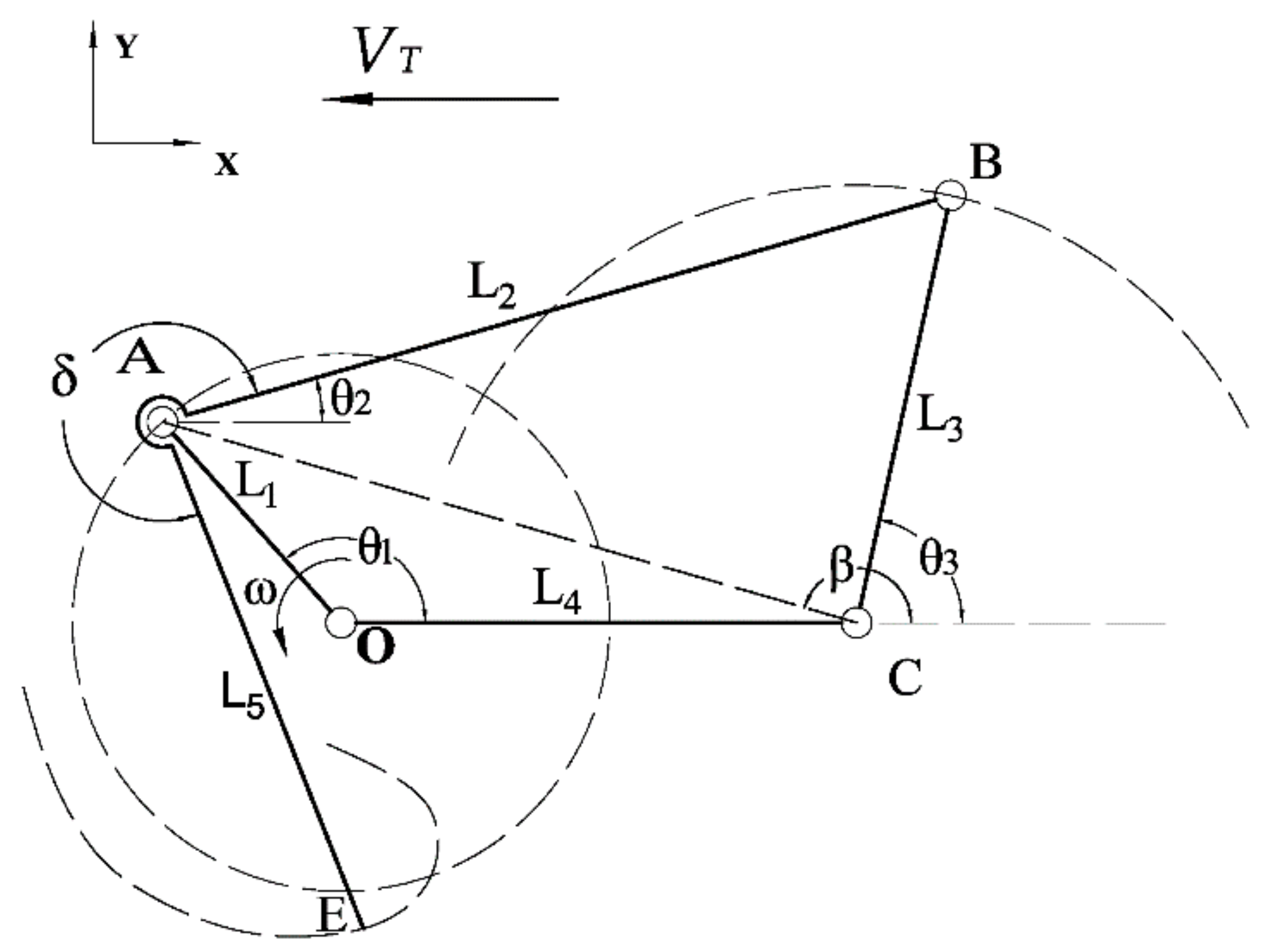
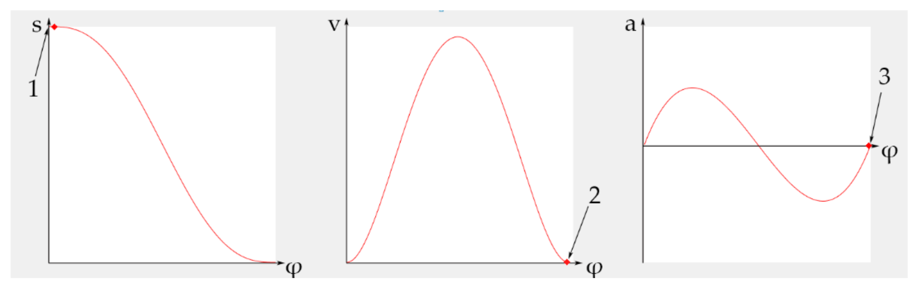
2.3. Kinematic Analysis of Four-Bar Mechanism

When transplanting, the shape of the sweet potato seedlings planted in the soil is consistent with the movement trajectory of the transplanting manipulator, and the trajectory is composed of horizontal forward and rotation movement. In order to realize the trajectory, we decided to adopt a four-bar mechanism as the prototype of the transplanting manipulator. The gripping levers of the transplanting manipulator are part of the connecting rod in the four-bar mechanism, as depicted in Figure 4. The four-bar mechanism’s kinematic analysis is shown below.
According to Figure 4, we established the vector equation of the four-bar mechanism [24]:
O A + A B = O C + C B O E = O A + A E
We established the displacement equation for point E:
x A + L 2 . c o s θ 2 = x C + L 3 . c o s θ 3 y A + L 2 . s i n θ 2 = y C + L 3 . s i n θ 3
x E = x A + L 5 . c o s θ 2 + δ y E = y A + L 5 . s i n θ 2 + δ
where x A = L 1 . c o s θ 1 ; y A = L 1 . s i n θ 1 .
θ 2 and θ 3 are unknown quantities in Equation (3), and x E and y E are unknown quantities in Equation (4). We can solve the displacement equation as follows.
Let   t g β = y A y C x A y C
In triangle ABC, ∠ACB = β θ 3 , so we can know:
cos β θ 3 = x A x C 2 + y A y C 2 + L 3 2 L 2 2 2 L 3 x A x C 2 + y A y C 2
We can thus obtain the value of β θ 3 , and the value of θ 3 . Moreover, we can determine that s i n θ 2 = y C + L 3 . s i n θ 3 y A L 2 , so we obtain the value of θ 2 . According to Equations (2) and (3), the equation of velocity is established.
Equation (6) is obtained by deriving Equations (3) and (4):
x A ˙ L 2 . θ 2 ˙ . s i n θ 2 = 0 L 3 . θ 3 ˙ . s i n θ 3 y A ˙ + L 2 . θ 2 ˙ . c o s θ 2 = 0 + L 3 . θ 3 ˙ . c o s θ 3
x E ˙ = x A ˙ L 5 . θ 2 ˙ . s i n θ 2 + δ y E ˙ = y A ˙ L 5 . θ 2 ˙ . c o s θ 2 + δ
where x A ˙ = L 1 . θ 1 ˙ . s i n θ 2 , and y A ˙ = L 1 . θ 1 ˙ . c o s θ 1 .
The velocity equation is solved as follows:
θ 2 ˙ = x A ˙ + y A ˙ . t g θ 3 L 2 . s i n θ 2 L 2 . t g θ 3 . c o s θ 3
Equation (9) can be obtained from Equation (6):
θ 3 ˙ = y O ˙ + L 2 . θ 2 ˙ . c o s θ 2 L 3 . c o s θ 3
x E ˙ and y E ˙ can be obtained from Equation (7).
The trajectory of point E has been obtained through the above theoretical analysis.

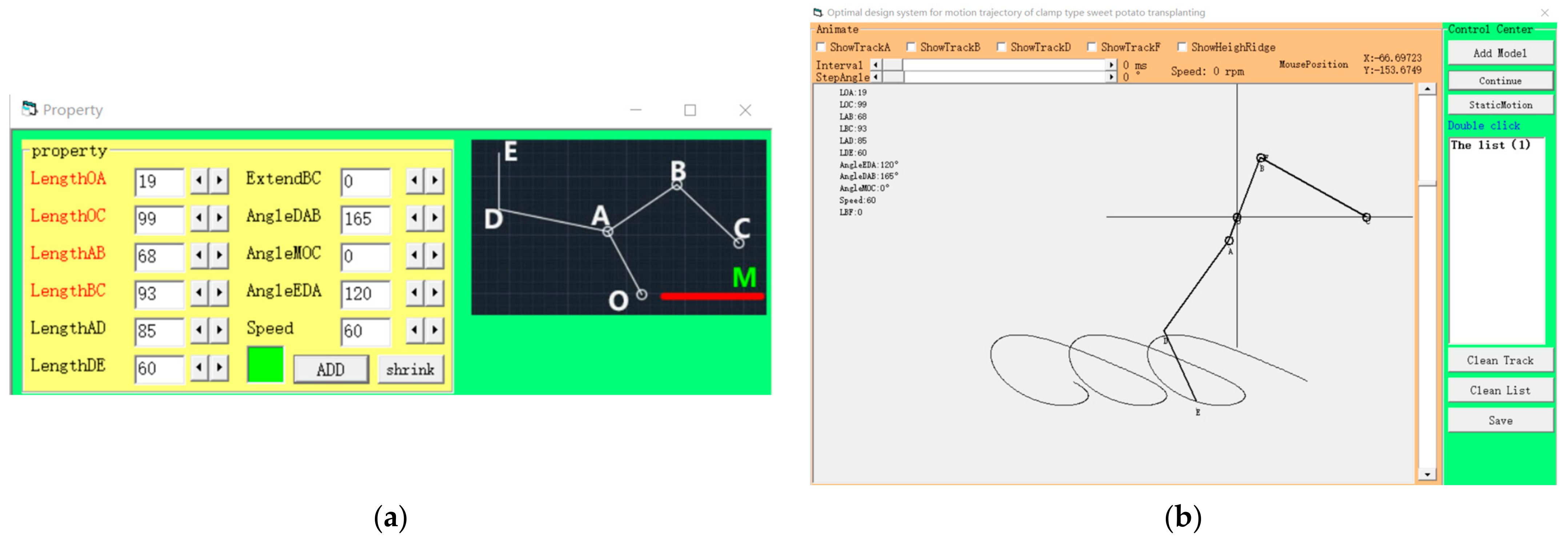
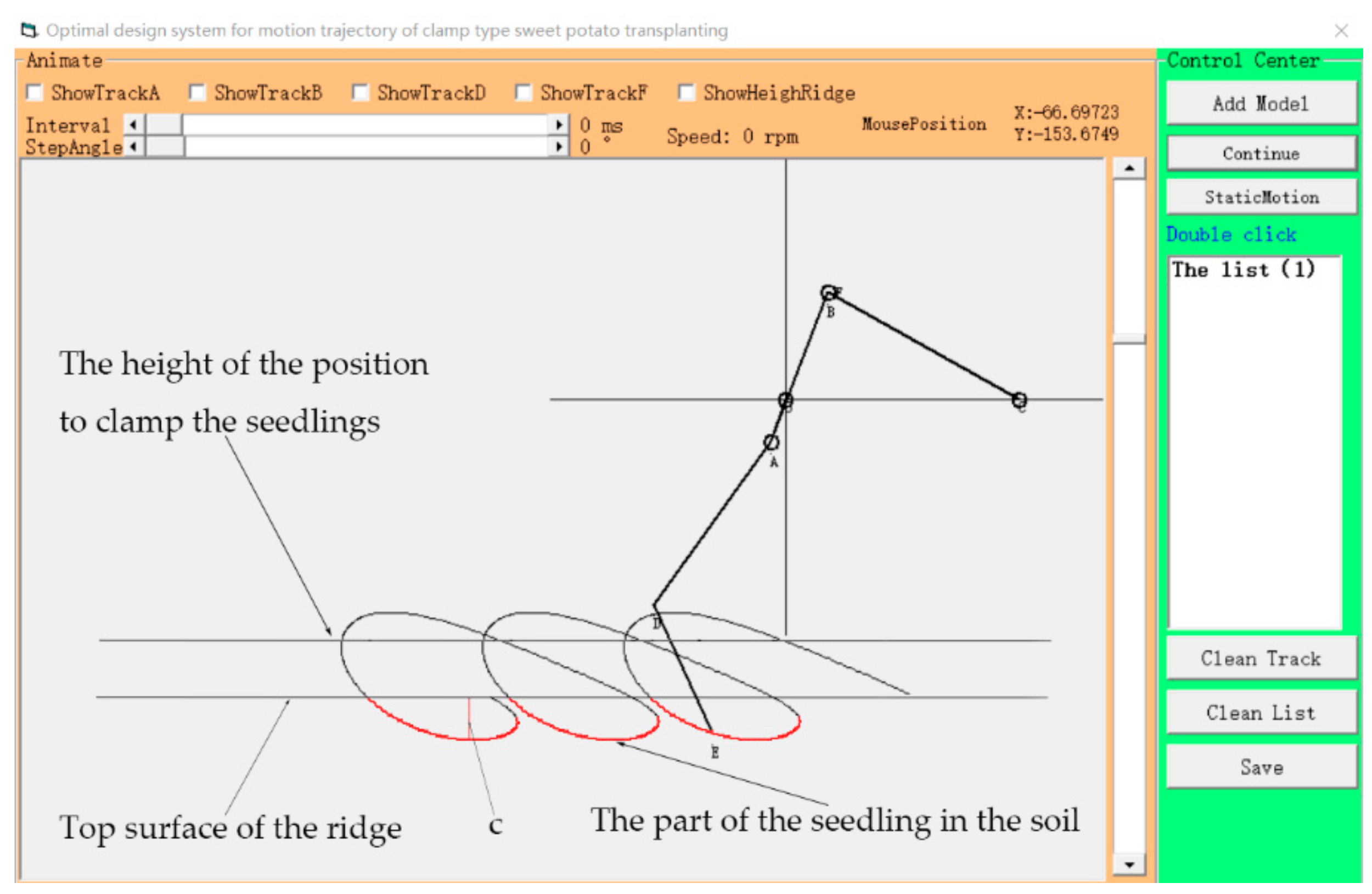
2.4. Determination of Parameters of Four-Bar Mechanism

According to the theoretical analysis in Section 2.3, we programmed the VB calculation program to adjust the parameters of the four-bar mechanism to obtain the ideal movement trajectory of point E. Finally, when the selected ratio of each rod is OA:OC:BC:AB:AD:DE = 19:99:93:68:85:60, and ∠EDA = 120°, ∠DAB = 165°, ∠MOC = 0°, the movement trajectory of the point E can meet the transplanting requirements of the boat-bottom-shaped insertion method. The proportional parameters of the four-bar mechanism and the motion trajectory of point E are shown in Figure 5.
As shown in Figure 6, according to the obtained trajectory shape, combined with the agronomic requirements of the boat-bottom-shaped insertion method, we can select the appropriate ridge top position; the ratio of the planting depth c to the actual planting depth a in the trajectory is used as a reference to restore the four bars’ actual value.
The value of c measured from UI is 4.65 mm. For the actual planting depth of sweet potato seedlings a, the value range is 40–60 mm, and 50 mm is taken for theoretical calculation, so Equation (10) can be obtained.
c a = 4.65 50
According to the proportional value of Equation (10), the length of each rod can be obtained: OA = 204 mm, OC = 1065 mm, BC = 1000 mm, AB = 731 mm, AD = 914 mm, DE = 645 mm.

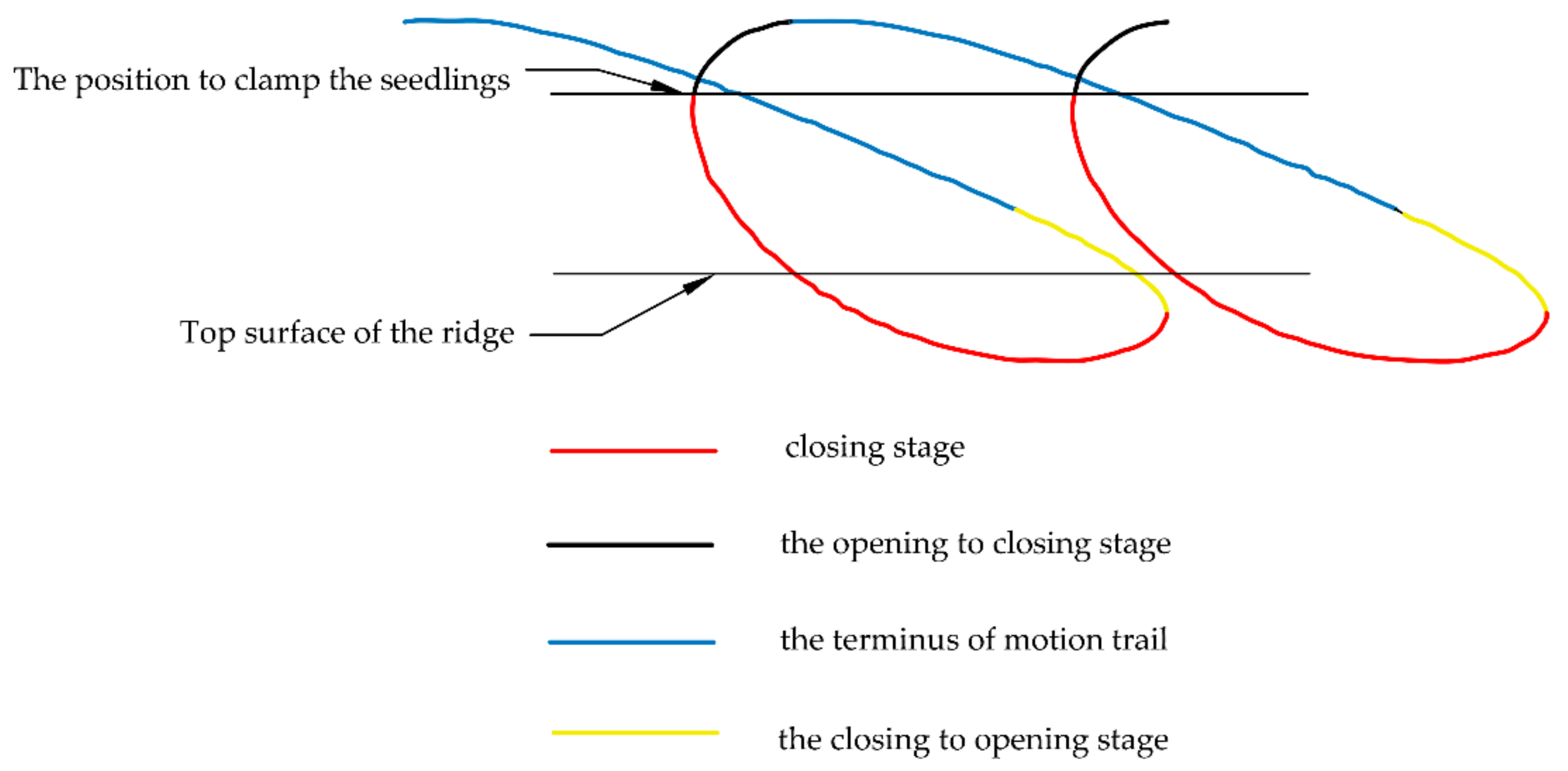
2.5. Designing to Prevent Damage Seedlings

After calculating the transplanting manipulator’s movement trajectory, the vertical heights of the three key points are used to confirm the movement strokes at various phases of the transplanting manipulator, as shown in Figure 7. The three key points include the location of clamping seedlings, the a value, and the b value.
The cam only controls the opening and closing of the transplanting manipulator and has no effect on the transplanting manipulator’s moving direction. Before designing the cam contour curve, according to the transplanting manipulator’s movement stroke, the cam edge contour curve is designed with four zones combined with the crank rotation angle: push zone, far rest zone, return zone, and near rest zone. The blue and red strokes correspond to the far rest zone and near rest zone, respectively. The black stroke corresponds to the return zone. The yellow stroke corresponds to the push stroke. The design of the return zone is the most important [25]. To prevent seedlings from being damaged by the gripping levers, the impact force at the moment of clamping seedlings must be zero. Therefore, at the end of the return zone, the moving speed and acceleration of the follower are zero, and the clamping force is only provided by the spring. To summarize, the motion law equation of the follower of the cam mechanism during the cam return stroke is designed as follows.
The displacement function of the cam mechanism’s follower can be expressed as.
s = s φ
where s is the linear motion displacement of the follower motion component, mm. φ is the cam angle variable and φ ϵ 0 , ϕ , rad.
According to the displacement function, the velocity and acceleration of the follower moving part are:
d s d φ = v ω m m / r a d d 2 s d φ 2 = a ω 2 m m / r a d 2
where the angular velocity of cam rotation is ω , rad/s.
Let the displacement function be:
s = c 0 + c 1 φ + c 2 φ 2 + c 3 φ 3 + c 4 φ 4 + c 5 φ 5 + + c n φ n
Let the constants higher than the fifth-order term in Equation (13) be zero, and the boundary condition of the cam return zone can be obtained as follows:
φ = 0 ,       s = 0 ,       d s d φ = 0 ,       d 2 s d φ 2 = 0 φ = ϕ ,       s = h ,       d s d φ = 0 ,       d 2 s d φ 2 = 0
The equation of motion for the return zone can be obtained as:
s = h 10 φ ϕ 3 15 φ ϕ 4 + 6 φ ϕ 5 d s d φ = 30 h ϕ φ ϕ 2 2 φ ϕ 3 + φ ϕ 4 d 2 s d φ 2 = 60 h ϕ 2 φ ϕ 3 φ ϕ 2 + 2 φ ϕ 3
where h is the descending height of the follower when the cam is working in the return zone.
Figure 8 shows the curve graph of the movement rule. The speed and acceleration of the quintic equation are all zero at the end of the return zone, and there is no sudden change in their curves. Therefore, this exercise law meets the requirements of low-damage seedlings.

3. Materials and Methods

Figure 9 illustrates the test procedure. The evaluation indexes and factors are first chosen in accordance with the analysis and relevant requirements. Then, using quadratic regression or orthogonal combination design tests, the field trial is performed to generate the regression equation corresponding to the evaluation index. To optimize the indexes and influencing factors, the regression equation is used. Finally, the results of the field testing are compared to the optimized outcome.

3.1. Key Performance Parameters of Planting Mechanism

In the measurement area, at least 300 sweet potato seedlings were tested in each group. The qualified rates of node depth in the seedling middle (QRNDSM), the qualified rates of seedling root depth (QRSRD), and the qualified rates of stalk length into the soil (QRSLS) were measured. The test method complies with the Group Standard of Sweet Potato Multi-Transplanter (T/CAAMM 52-2020). The QRNDSM is calculated according to Equation (16), the QRSRD is calculated according to Equation (17), and the QRSLS is calculated according to Equation (18).

3.1.1. QRNDSM

QRNDSM is qualified within the range of 40 to 60 mm, and the QRNDSM y 1 is calculated as follows:
y 1 = m 1 300 × 100 %
where y 1 is QRNDSM/%; m 1 is the qualified node depth in the seedling middle, mm.

3.1.2. QRSRD

QRSRD is qualified within the range of 20 to 30 mm, and the QRSRD y 2 is calculated as follows:
y 2 = m 2 300 × 100 %
where y 2 is QRSRD/%; m 2 is the qualified seedling root depth, mm.

3.1.3. QRSLS

QRSLS is qualified within the range of 180 to 220 mm, and the QRSLS y 2 is calculated as follows:
y 3 = m 3 300 × 100 %
where y 3 is QRSLS/%; m 2 is qualified stalk length into the soil, mm.

3.2. Determine the Scope of Test Factors

3.2.1. Analysis of Crank Rotation Speed Range

In the actual work of the sweet potato boat-bottom-shaped transplanting, there is a movement stage in which the seedling stalk moves upward in the soil. The stalk will be subjected to the longitudinal resistance of the soil, and the actual transplanting depth of sweet potato seedlings will be different from the theoretical transplanting depth. According to the characteristics of fluid mechanics, the more quickly the machine moves, the more opposition it encounters. The crank’s rotational speed is most directly related to the movement speed of the stalks of the seedlings in the soil. Therefore, the crank rotation speed is determined as one of the test factors. The limit speed of artificial release seedlings is 60 plants/min; that is, the maximum rotation of the crank is 60 plants/min. According to the Group Standard of Sweet Potato Multi-Transplanter, the transplanting speed shall not be less than 35 plants per minute. Therefore, the range of crank rotation speed is 35–60 rpm.

3.2.2. Analysis of the Range of Transplanting Depth

In order to explore the influence of transplanting depth on the qualified rate in actual transplanting work, combined with the deepest range of 40–60 mm for seedling transplanting, the whole transplanting device was designed as a structure that can slide up and down. The deepest b value that suits the boat-bottom shape can be adjusted arbitrarily within the range of 40–60 mm.

3.3. Field Test Materials

The test site was the field of Shandong Huorong Agricultural Science and Technology Development Co., Ltd. in Qingzhou City, Weifang City. As shown in Figure 10, it is the structure diagram of the whole machine and the pictures of the test site. The transplanted variety was Yanshu 25. The seedling age was 35 days, the average weight of 100 sweet potato seedlings was more than 500 g, and the length of the sweet potato seedlings was 200–250 mm. The stems were strong and thick. The internodes were short (30–50 mm). The seedlings had 5–7 nodes, the leaves were plump, the size was moderate, the color was bright green, and there was no air rooting on the stems. The sweet potato seedlings were free of disease spots, and the stalk and roots were white and tender. During the experiment, the average seedling length was 236 mm and the average diameter at 20 mm from the seedling root was 4.28 mm.

3.4. Methods of Field Test

The transplanting depth z1 and crank rotation speed z2 were used as experimental parameters in conjunction with the preceding analysis and the prototype’s real functioning conditions. Table 1 provides a summary of the experimental variables and their respective magnitudes.
Orthogonal quadratic regression with four zero-level tests (m0 = 4), r = 1.21 [26], was employed in the experiment. Before performing the experiment, all of the variables were coded. The coding procedure is presented in Table 2.
The test evaluation indexes employed were the QRNDSM, the QRSRD, and the QRSLS. There were 12 tests in total, and the average value was calculated by running each set of tests three times. Table 3 summarizes the test strategy and the associated findings.

4. Results and Discussion

4.1. Filed Test Results

Using an orthogonal quadratic regression, the results of the test project and field tests are shown in Table 3, while Table 4, Table 5 and Table 6 exhibit the regression analysis results. When the transplanting device was constructed, it had the ability to accomplish the transplanting operation with a boat-shaped transplanting effect, as shown in Figure 11.

4.2. Filed Test Regression Analysis

The p-value of the lack of fitness Pl is 0.5256, as shown in Table 4, suggesting that the experimental index’s regression equation fits well. We regarded it as the significance level when taking α = 0.05. The primary term x2 and square term x22 have highly significant impacts, the primary term x1 has significant effects, and the other components have no significant effects. The final equation in terms of coded factors is derived after deleting the insignificant terms:
y ^ 1 = 93.88 + 0.7154 x 1 1.49 x 2 1.6 x 2 2
It can be shown from Equation (19) that the crank rotation speed has more influence on QRNDSM than transplanting depth. After sorting, the true QRNDSM regression equation was found by Table 2:
y 1 = 62.5424 + 0.0866 z 1 + 1.2819 z 2 0.015 z 2 2
The p-value of the lack of fitness Pl is 0.2537, as shown in Table 5, suggesting that the experimental index’s regression equation fits well. We regarded it as the significance level when taking α = 0.05. The primary term x2 and square term x22 have highly significant impacts, the primary term x1 has significant effects, and the other components have no significant effects. The final equation in terms of coded factors after deleting the insignificant terms is as follows:
y ^ 2 = 94.14 0.6933 x 1 1.84 x 2 1.18 x 2 2
It can be shown from Equation (21) that the crank rotation speed has more influence on QRSRD than transplanting depth. After sorting, the true QRSRD regression equation was determined by Table 2:
y 2 = 81.9245 0.0839 z 1 + 0.8684 z 2 0.011 z 2 2
The p-value of the lack of fitness Pl is 0.0086, as shown in Table 6, suggesting that the experimental index’s regression equation fits well. We regarded it as the significance level when taking α = 0.05. The principal terms x1 and x2 as well as the square term x22 have highly significant effects, and the square term x12 has significant effects, whereas the other components have no effect. The final equation in terms of coded factors is derived after deleting the insignificant terms:
y ^ 3 = 94.46 + 0.726 x 1 1.37 x 2 0.6596 x 1 2 1.75 x 2 2
Transplanting depth has more influence on QRSLS than crank rotation speed, as shown by Equation (23). After sorting, the true QRSLS regression equation was derived by Table 2:
y 3 = 35.1835 + 1.0536 z 1 + 1.4272 z 2 0.0097 z 1 2 0.0164 z 2 2
Table 7 describes the analysis of regression. The R values of QRNDSM y1, QRSRD y2, and QRSLS y3 are equal to 0.9728, 0.9672, and 0.9850, respectively, suggesting that the regression model’s experimental variables and test indicators have an intense linear relationship. For QRNDSM y1, QRSRD y2, and QRSLS y3, the coefficients of determination R2 are 0.9464, 0.9356, and 0.9703, respectively, indicating a high degree of fit for the regression model. To avoid the confine from determination coefficient R2, an adjusted coefficient of determination Adj R2 is acquired. According to the results, the adjusted determination coefficient for the QRNDSM qualified rate y1 is 0.9494, showing that the model could explain 94.96% of the variation in QRNDSM y1. Similarly, the adjusted determination coefficient of the QRSRD y2 is 0.9391, which shows that the model could explain 93.91% of the variation in QRSRD y2. The adjusted determination coefficient of the QRSLS y3 is 0.9724, showing that the model could explain 97.24% of the variation in QRSLS y3. The statistic of Durbin–Watson meets the requirements of 1 < d < 3 simultaneously, indicating that the test data are highly reliable.
Figure 12 displays the comparison between the curve of the test value and the curve of the fitted value from the three regression models. The blue line represents the test measured values, and the orange line represents the sample fitted values. The two values are quite closely matched, as can be seen.

4.3. Filed Test Interaction Analysis

The regression equations were transformed into three-dimensional contour maps, as illustrated in Figure 13, Figure 14 and Figure 15, in order to more intuitively understand the effect rules of test factors on the three experiment indices and investigate the interaction of the two factors.

4.3.1. Influence of Transplanting Depth and Crank Rotation Speed on QRNDSM

As shown in Figure 13, (1) the crank rotation speed has a major influence on QRNDSM under the circumstance of stable transplanting depth, and the QRNDSM lowers as the de-crank rotation speed increases, and (2) under the condition of stable crank rotation speed, the transplanting depth has a significant influence on QRNDSM, and the QRNDSM increases with the increase in the transplanting depth. The reason for this phenomenon is that during the transplanting process, the disturbance of the transplanting manipulator will soften the soil above the sweet potato seedlings and the soil will be thrown backwards, and the pressure on the upper soil to the stalk will become very small. During the process of the seedlings moving with the transplanting manipulator, the sweet potato seedlings conform to the set transplanting trajectory, but because the stems of the sweet potato seedlings are elastic, the middle part of the seedlings will rebound upward after the separation between the transplanting manipulator and the seedlings, resulting in a shallower actual transplanting depth. The above explanation also shows that increasing the transplanting depth will increase the QRNDSM.
The research of Hu et al. [27] showed that the theoretical transplanting depth will be less than the actual transplanting depth. When the designed transplanting depth is the minimum value of the qualified depth range, the qualified rate will be much lower than other designed values of the qualified depth range. The research of Yu et al. [28] showed that the qualified rate of transplanting showed an upward trend with the increase in designed transplanting depth, and the designed transplanting depth is within the qualified range. In order to ensure a higher QRNDSM, the theoretical planting depth can be within the range of 50–60 mm, and the crank rotation speed should be in the range of 35–47.5 rpm.

4.3.2. Influence of Transplanting Depth and Crank Rotation Speed on QRSRD

As shown in Figure 14, under the condition of stable transplanting depth, the crank rotation speed has a significant effect on QRSRD, and the QRSRD decreases with the increase in crank rotation speed. Under the condition of stable crank rotation speed, the transplanting depth has a significant effect on QRSRD, and the QRSRD diminishes as the depth of the transplantation is increased. The reason for this phenomenon is that the position where the seedlings are clamped at the stalk about 2 cm away from the roots of the seedlings, during the upward movement of seedlings’ roots, downward resistance from the soil will be encountered. According to the characteristics of the fluid, the faster the movement speed, the greater the resistance of the soil, which causes the seedling roots’ actual transplanting depth to be less than the theoretical depth. The above explanation also explains why the QRSRD decreases with the increase in transplanting depth. In order to ensure that QRSRD has a higher qualified rate, the transplanting depth can be selected between 40 and 55 mm, and the crank rotation speed can be selected between 35 and 47.5 rpm.

4.3.3. Influence of Transplanting Depth and Crank Rotation Speed on QRSLS

As shown in Figure 15, (1) under the condition of stable transplanting depth, the crank rotation speed has a certain effect on QRSLS, and the QRSLS decreases with the increase in crank rotation speed, and (2) under the condition of stable crank rotation speed, the transplanting depth has a significant effect on QRSLS, and the QRSLS increases with the increase in the transplanting depth. The reason for phenomenon (1) is that the deeper the transplanting depth, the longer the seedling stalk’s length is buried in the soil, which is the same as the reason analyzed in Section 4.3.1. The reason for phenomenon (2) is that when the transplanting speed accelerated, the degree of the soil’s disturbance above the seedlings by the transplanting manipulator increased, causing the seedling stalks to rebound upward under the action of its elastic force, which is the same as the reason analyzed in Section 4.3.1.
The research of Zhang et al. [29] showed that the qualified rate of transplanting depth has a certain relationship with the theoretical transplanting depth. Within the qualified range of the theoretical depth, the test results show that when the depth value is small, the qualified rate of the transplanting depth is not as good as other value of the depth range. In order to ensure that QRSLS has a higher qualified rate, the theoretical transplanting depth can be 45–60 mm, and the crank rotation speed range is 35–47.5 rpm.

4.4. Comparison and Field Test Performance Optimization

Three qualified rates must be satisfied after transplanting naked sweet potato seedlings, according to the conditions for transplanting naked sweet potato seedlings. The QRNDSM is the first, the QRSRD is the second, and the QRSLS is the third. We created an objective function for the three indicators listed above and used it to replace the regression model. The following is a description of the objective function and constraints:
F m a x z = y 1 z 1 , z 2 y 2 z 1 , z 2 y 3 z 1 , z 2 s . t . 40   m m z 1 60   m m 35   r p m z 2 60   r p m
The response surface optimization method of Design-Expert was used to optimize the parameters. When the transplanting depth is 58.26 mm and the crank rotation speed is 41.83 rpm, the QRNDSM reaches the maximum 94.91%. When the transplanting depth is 45.56 mm and the crank rotation speed is 39.39 rpm, the QRSRD reaches the maximum of 95.42%. When the transplanting depth is 54.55 mm and the crank rotation speed is 43.45 rpm, the QRSLS reaches the maximum of 94.93%. This test used the same Yanshu 25 variety as the orthogonal regression. Triplicate experiments were performed, with the average values taken. Table 8 displays the results. The results of the tests reveal that the value obtained from the field test verification is extremely similar to the theoretical value obtained from the ideal parameter test.
No matter what kind of planting method is used, in order to achieve a more accurate planting form, the most direct method is to study the movement trajectory of the end of the planting mechanism. There has been a significant amount of investigation into the motion trajectory of the transplanting mechanism’s executive end. Xu [30] carried out computer programming according to the mathematical model of the planting mechanism, developed the human–computer interaction visual auxiliary interface of the planting mechanism, and studied the influence of the parameters of the mechanism on the trajectory of the end point of the planting mechanism. The final field test results illustrated that the qualified rate of planting depth fluctuated slightly around 83.3%. According to the kinematic model of the end point of the planting mechanism, Wang [31] used Origin to analyze the motion trajectories under different parameters, and selected the trajectory with the highest comprehensive score. According to the parameters under the trajectory, the prototype was tested in the field. The final field test results illustrated that the qualified rate of planting depth fluctuated slightly around 87.17% The qualified rate of transplanting depth in this paper is above 90%, and the reliability of the machine is better than most of the existing machines.
At present, sweet potato transplanters around the world generally employ the oblique insertion method. Because the boat-bottom-shaped insertion method needs a special trajectory for the transplanting track mechanism, there are a few studies on this method. The existing research on the boat-bottom-shaped insertion method is still in the stage of bench tests [19] (pp. 52−60). Compared with the test results of this study and the research progress, the qualified rate of the length of the seedlings into the soil has increased by more than 12%, and the qualified rate of the transplanting depth has increased more than 10%.

5. Conclusions

(1)
In order to carry out boat-bottom-shaped transplanting for sweet potato, we studied the basic parameters of the transplanting device theoretically. Then, we collected and sorted the information on the existing transplanting machine and analyzed the transplanting device’s movement trajectory to ensure its rationality and reliability. Next, we combined the characteristics of boat-bottom-shaped transplanting, designed the transplanting manipulator and the transplanting conveying device to move synchronously, and selected the movement track of the transplanting manipulator to realize the boat-bottom-shaped transplantation of sweet potato seedlings.
(2)
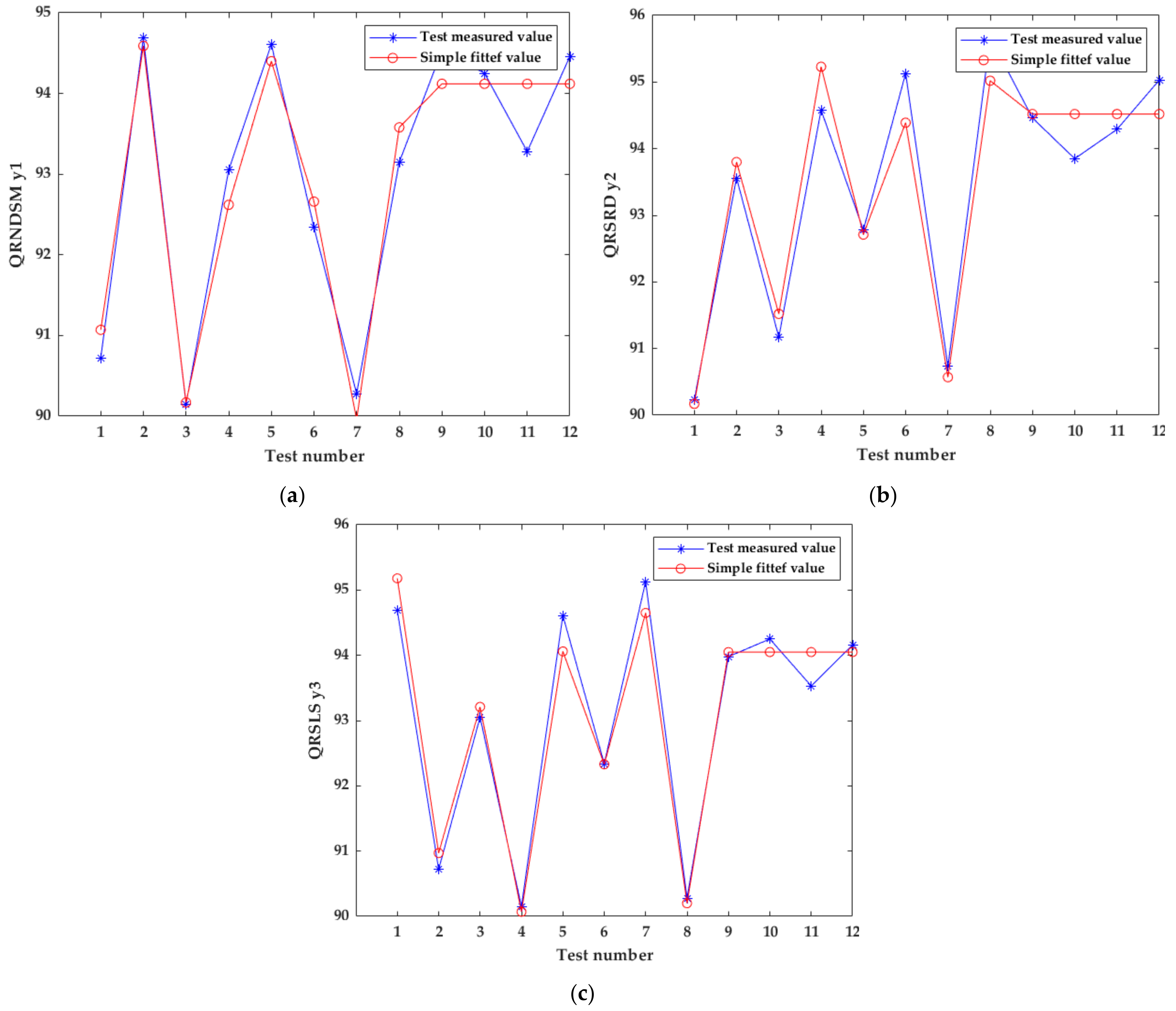
Through the analysis of the agronomic requirements for the boat-bottom-shaped transplanting of sweet potato and the mechanical properties of soil, the transplanting depth and crank rotation speed were used as test factors. We determined that the transplanting depth range is 40–60 mm, and the crank rotation speed range is 35–60 rpm. In field tests, QRNDSM, QRSRD, and QRSLS were used as the test evaluation indexes, and binary regression and orthogonal combination tests were carried out. After processing and analyzing the test data, three quadratic regression models of the three test evaluation indexes were obtained. The significance analysis of the regression coefficients shows that the regression models have high degrees of fit. At the same time, the experimentally measured values of the three regression models are close to the fitted values.
(3)
Through the analysis of the interaction of the two factors, it can be concluded that the interaction of the two factors has a significant impact on the three test evaluation indicators. Through optimized calculation, the optimal parameter ranges of the transplanting device were obtained: the transplanting depth was in the range of 45.56–58.26 mm, and the crank rotation speed was in the range of 39.39–43.45 rpm. In the field verification test, the maximum QRNDSM was 94.91%, the maximum QRSRD was 95.42%, and the maximum QRSLS was 94.93%.
(4)
Boat-bottom-shaped transplanting has higher yield than the current common oblique transplanting method, so growers are more willing to choose this system to increase sweet potato yields. This supply–demand relationship has brought considerable benefits to both farmers and producers. Field tests show that the qualified rate of each test index is above 90%, which proves that the machine has high reliability and stability. However, the automatic seedling separation technology of sweet potato remains an unsolved problem around the world—the future research aim of our team is to solve it.

Author Contributions

Conceptualization, Z.P. and L.L.; Data curation, L.L. and D.C.; Formal analysis, Z.P. and L.L.; Funding acquisition, R.Y.; Investigation, Z.P. and R.Y.; Methodology, Z.P. and L.L.; Project administration, R.Y.; Resources, Z.P. and D.C.; Software, Z.P. and L.L.; Supervision, R.Y.; Validation, Z.P., L.L., D.C. and X.Z.; Visualization, Z.P. and D.C.; Writing—original draft, Z.P. and L.L.; Writing—review and editing, Z.P. and L.L. All authors have read and agreed to the published version of the manuscript.

Funding

Financial assistance for this project was provided as part of the research and development of key technologies and equipment for the mechanized production of sweet potato and carrot (grant no. SD2019NJ009), under the Shandong Province Agricultural Major Application Technology Innovation Project.

Institutional Review Board Statement

Not applicable.

Informed Consent Statement

Not applicable.

Data Availability Statement

All data in this paper can be requested from the second author ([email protected]).

Acknowledgments

Funding for this research came from the Shandong Province Agricultural Major Application Technology Innovation Project (research and development of key technologies and equipment for mechanized production of sweet potato and carrot, SD2019NJ009). All authors would like to express our gratitude to Huade Gao for assisting us in this sweet potato agronomic research and in renting the test site.

Conflicts of Interest

The authors jointly declare no conflict of interest.

References

  1. Hu, L.; Hu, Z.; Xie, Y.; Tian, L.; Ji, F.; Wang, B. Study on the route of mechanization of sweet potato production technology in China. Chin. Agric. Mech. 2011, 6, 20–25. [Google Scholar] [CrossRef]
  2. Hou, M.; Li, Q.; Xin, G.; Wu, W.; Wang, L.; Wang, X.; Zhang, Y.; Tang, Z.; Tang, W.; Li, X.; et al. Variability of sweet potato storage root under different ecological environments and its correlation with quality traits. Chin. J. Eco-Agric. 2013, 21, 1095–1099. [Google Scholar] [CrossRef]
  3. Li, H. Development status of sweet potato mechanization industry at home and abroad. Jiangsu Agric. Mech. 2010, 2, 40–42. [Google Scholar] [CrossRef]
  4. Hu, L.; Ji, F.; Wang, B.; Ling, X.; Hu, Z.; Yu, X. Latest development of sweet potato mechanical transplanting in China. J. Chin. Agric. Mech. 2015, 36, 289–291. [Google Scholar] [CrossRef]
  5. Wu, Y.; Gong, Z.; Chang, G.; Zhu, Y. Design and Experiment of Type 2ZLF-2 Duplex Sweet Potato Transplanter. Agric. Equip. Veh. Eng. 2021, 59, 54–57. [Google Scholar] [CrossRef]
  6. Ma, B.; Hu, L. Status about sweet potato planting and its production machinery in China. Chin. Agric. Mech. 2013, 1, 42–46. [Google Scholar]
  7. Fang, B.; Zhang, X.; Chen, J.; An, K. Research history and present situation sweet potato germplasm resource in China. Guangdong Agric. Sci. 2004, B12, 3–5. [Google Scholar] [CrossRef]
  8. Li, R.; Zhao, J.; Zhang, X.; Zhang, Z.; Wang, L. Relationship between transplanting methods and yield characters of sweet potato. Crops 2015, 5, 164–166. [Google Scholar] [CrossRef]
  9. Teng, Y. Effect of Vine Character on Growth and Development and Yield of Xushu 22; Southwest University: Chongqing, China, 2014. [Google Scholar]
  10. Shen, S.F.; Wu, L.H.; Li, B. Studies on ridge plowing ways of spring sweet potato. Acta Agric. Zhejiangensis 2014, 26, 549–555. [Google Scholar]
  11. Ma, D.F.; Li, Q.; Cao, Q.H. Development and prospect of sweet potato industry and industrial technology in China. Jiangsu J. Agric. Sci. 2012, 28, 969–973. [Google Scholar]
  12. Ma, B.; Hu, L.L.; Xu, L.Y.; Tian, L.J.; Ji, F.J.; Wang, B. Domestic sweet potato planting and its production machinery. Chin. Agric. Mech. 2013, 1, 42–46. [Google Scholar]
  13. Xiang, W.; Wu, M.L.; Guan, C.Y. Design and experiment of planting hole forming device of crawler transplanter for rape (Brassica napus) seedlings. Trans. Chin. Soc. Agric. Eng. 2015, 31, 12–18. [Google Scholar]
  14. Lu, Y.T.; Li, Y.X.; Liu, Y. Analysis on the status of transplanting machine and transplanting technology at home and abroad. Xinjiang Agric. Mech. 2011, 3, 29–32. [Google Scholar]
  15. Li, X.Y.; Wang, Y.W.; Lu, G.C. Optimization design and test of dibble-type transplanting device. Trans. Chin. Soc. Agric. Eng. 2015, 31, 58–64. [Google Scholar]
  16. Wang, M.M.; Song, J.N.; Liu, C.L. Design and experiment of crank rocker type clamp seedlings mechanism of vegetable transplanter. Trans. Chin. Soc. Agric. Eng. 2015, 31, 49–56. [Google Scholar]
  17. Hu, L.L.; Wang, B.; Wang, G.P.; Yu, Z.Y.; You, Z.Y.; Hu, Z.C. Design and experiment of 2zgf-2 type sweet potato compound transplanter. Trans. Chin. Soc. Agric. Eng. 2016, 32, 16–24. [Google Scholar]
  18. Zhu, B. Design and Simulation of the Seedling Transplanting Machine with Sandwich Type Sweet Potato; Shandong Agricultural University: Tai’an, China, 2017. [Google Scholar]
  19. Zhang, T. Design and Experiment of Transplanting Device for Naked Sweet Potato Seedlings on Film based on “Boat Shape” Posture; Shandong Agricultural University: Taian, China, 2021. [Google Scholar] [CrossRef]
  20. Xu, G.; Liu, H.; Jian, S.; Shi, S.; He, T. Design and Test of Transplanting Mechanism on Mulch-film of Salvia miltiorrhiza Based on Five-bar Mechanism. Nongye Jixie Xuebao/Trans. Chin. Soc. Agric. Mach. 2018, 49, 55–65. [Google Scholar] [CrossRef]
  21. Chen, J. Design and Research on the Control System of Precise Planting of Sweet Potato Seedlings. Guangxi Univ. 2021. [Google Scholar] [CrossRef]
  22. Zhuang, R. Optimization Design and Experimental Study on Transplanting Mechanism of Sweet Potato Seed Seedlings. Zhejiang Sci-Tech Univ. 2021. [Google Scholar] [CrossRef]
  23. Sweet Potato Compound Planting Machine Group Standard. China Agricultural Machinery Industry Association: Beijing, China, 2020.
  24. Yun, Z. Analysis and Synthesis of Agricultural Machinery; China Machine Press: Hangzhou, China, 2008; ISBN 978-7-111-25000-5. [Google Scholar]
  25. Shi, Y.; Wu, Y. Cam Mechanism Design and Application Innovation; Machinery Industry Press: Beijing, China, 2007; ISBN 978-7-111-21936-1. [Google Scholar]
  26. He, Y. Experimental Design and Analysis; Chemical Industry Press: Beijing, China, 2013. [Google Scholar]
  27. Hu, L.; Wang, B.; Wang, G.; Yu, Z.; You, Z.; Hu, Z.; Wang, B.; Gao, X. Design and experiment of type 2ZGF-2 duplex sweet potato transplanter. Int. J. Agric. Biol. Eng. 2016, 32, 8–16. [Google Scholar]
  28. Yu, Y.; Qin, W.; Lai, Q.; Zhang, H. Design and Experiment of Planting Mechanism of Cauliflower Pot Seedling Transplanter, Transactions of the Chinese Society for Agricultural Machinery. Trans. Chin. Soc. Agric. Mach. 2020, 51, 102–112. [Google Scholar] [CrossRef]
  29. Zhang, J.; Niu, Z.; Li, T.; Wu, Y.; Xi, R.; Li, G.; Hou, J. Design and Optimization of Planting Process Parameters for 2ZYX-2 Type Green Onion Ditching and Transplanting Machine. Phyton-Int. J. Exp. Bot. 2020, 89, 147. [Google Scholar] [CrossRef]
  30. Xu, G. Key Components Research and Design of Double-Row Crossing Salvia Miltiorrhiza Transplanter on Mulch-Film of Big Ridge; Northeast Agricultural University: Haerbing, China, 2020. [Google Scholar]
  31. Wang, Y. Design and Study on Transplanting Mechanism of Staggered Chain Type Transplanting Machine; Shihezi University: Shihezi, China, 2018. [Google Scholar]
Figure 1. Schematic diagram of the boat-bottom-shaped insertion method: a is the node depth in the seedling middle, b is the seedling root depth.
Applsci 12 02817 g001
Figure 2. Working diagram of the transplanting device. (a) Top view of transplanting device, (b) transplanting conveyor device, and (c) transplanting manipulator.
Applsci 12 02817 g002
Figure 3. Drive system schematic: the sprocket 1 outputs power to the transplanting conveying device 2; the sprocket is linked with the main power shaft (3 and 4); 5 is the bevel gear; 6 is the power gear of the transplanting conveying device; 7 is the power gear of the crank; 8 is the power shaft linked with the crank; 9 represents the sprocket outputting power to the transplanting manipulator; and 10 is the main power shaft of the ground wheel.
Applsci 12 02817 g003
Figure 4. Analysis of the four-bar mechanism. VT is the forward speed of the transplanter during field work; OA is the crank; O is the crank rotation center; BAE is the link; AE is the gripping lever; BC is the rocker; OC is the frame; the length of OA is L1, mm; the length of AB is L2, mm; the length of BC is L3, mm; the length of OC is L4, mm; the length of AE is L5, mm; the angle formed by OA and OC is denoted by θ1, °; the angle formed by AB and the horizontal plane is denoted by θ2, °; the angle formed by BC and the horizontal plane is denoted by θ3, °; the angle of ∠BAE is δ ,°; the angle of ∠BCA is β , °.
Applsci 12 02817 g004
Figure 5. Optimizing system interface for transplanting manipulator. (a) Interface for adjusting parameters; (b) interface showing movement trajectory.
Applsci 12 02817 g005
Figure 6. The part of seedling’s stalk in the soil.
Applsci 12 02817 g006
Figure 7. The trajectory corresponding to each movement stage of the cam.
Applsci 12 02817 g007
Figure 8. The displacement, velocity, and acceleration curves of the follower when the cam is working in the return zone. (1) The descending height h of the follower in the return zone (2). The movement speed of the follower at the end of the return zone (3). The movement acceleration of the follower at the end of the return zone.
Applsci 12 02817 g008
Figure 9. Materials and methods flow chart.
Applsci 12 02817 g009
Figure 10. Transplanting manipulator and transplanting conveying device of sweet potato transplanting machine. (a) Diagram of the structure, (b) photo of a real machine.
Applsci 12 02817 g010
Figure 11. Transplanting renderings. (a) Boat-bottom-shaped transplanting, (b) plant spacing measurement.
Applsci 12 02817 g011
Figure 12. The comparison between the curve of the test value and the curve of the fitted value. (a) QRNDSM, (b) QRSRD, (c) QRSLS.
Applsci 12 02817 g012
Figure 13. The interaction of transplanting depth and crank rotation speed on QRNDSM.
Applsci 12 02817 g013
Figure 14. The interaction of transplanting depth and crank rotation speed on QRSRD.
Applsci 12 02817 g014
Figure 15. The interaction of transplanting depth and crank rotation speed on QRSLS.
Applsci 12 02817 g015
Table 1. Experimental factors and levels.
FactorsTransplanting Depth
z1/(mm)
Crank Rotation Speed
z2/(rpm)
Levels
14035
25047.5
36060
Table 2. Experimental factor coding approach.
FactorsTransplanting Depth
z1/(mm)
Crank Rotation Speed
z2/(rpm)
Code
r (Z2j)6060
1(Z0j + Δj)58.26557.831
0(Z0j)5047.5
1(Z0j − Δj)41.73537.169
r (Z1j)4035
Δj = (Z2jZ1j)/2r8.26410.331
xj = (ZjZ0j)/Δjx1 = 0.121(z1 − 50)x2 = 0.097(z2 − 47.5)
Note: Δj is the j-th factor’s minimal change interval, j = 1, 2; the encoded factor is xj and the asterisk arm is r.
Table 3. Orthogonal quadratic regression test program and results.
Factorsx0x1x2x1x2x12x22y1y2y3
Test
111111190.7290.2390.83
211−1−11194.6993.5694.52
31−11−11190.1591.1790.23
41−1−111193.0594.5892.97
51r00r2094.6192.7894.57
61r00r2092.3495.1392.19
710r00r290.2890.7390.51
810r00r293.1595.6793.05
910000094.5394.4694.47
1010000094.2593.8594.38
1110000093.2894.2994.52
1210000094.4695.0394.61
Note: xj is the encoded factor, with j = 1 or 2, and r being the asterisk arm.
Table 4. QRNDSM variance analysis.
SourceSquared SumFreedom LevelMean SquareF Valuep-Value
Model29.9936.1921.190.0010 **
x13.5513.5510.40.0121 *
x215.44115.4445.300.0001 **
x2211.01111.0132.290.0005 **
Residuals2.7380.3409//
Lack of Fitness1.7250.34421.030.5256
Pure Error1.0130.3353//
Cor Total32.7211///
Note: ** expresses highly significant (p ≤ 0.01); * expresses significant (0.01 ≤ p ≤ 0.05).
Table 5. QRSRD variance analysis.
SourceSquared SumFreedom LevelMean SquareF Valuep-Value
Model32.60310.8720.500.0004 **
x13.3313.336.280.0366 *
x223.34123.3444.040.0002 **
x225.9215.9211.170.0102 **
Residuals4.2480.5300//
The Lack of Fitness3.5350.70512.960.2005
Pure Error0.714930.2383//
Cor Total36.8411///
Note: ** expresses highly significant (p ≤ 0.01); * expresses significant (0.01 ≤ p ≤ 0.05).
Table 6. QRSLS variance analysis.
SourceSquared SumFreedom LevelMean SquareF Valuep-Value
Model31.7247.9346.07<0.0001 **
x13.6513.6521.220.0025 **
x213.04113.0475.74<0.0001 **
x121.8711.8710.840.0133 *
x2213.17113.1776.50<0.0001 **
Residuals1.2070.1721//
The Lack of Fitness1.1840.294331.870.0086
Pure Error0.027730.0092//
Cor Total32.9211///
Note: ** expresses highly significant (p ≤ 0.01); * expresses significant (0.01 ≤ p ≤ 0.05).
Table 7. Analysis of the significance of the regression coefficient on the test results.
Inspection Itemsy1y2y3
R0.97280.96720.9850
R20.94640.93560.9703
Adj R20.94960.93910.9724
S0.54060.62900.4040
Durbin–Watson
Statistic
2.6552
(1 < d < 3)
1.8228
(1 < d < 3)
2.9930
(1 < d < 3)
Table 8. Test results for the best parameters.
QRNDSM
y1/%
QRSRD
y2/%
QRSLS
y3/%
Theoretical value94.9195.4294.93
Field test validation value94.8395.4794.86
Publisher’s Note: MDPI stays neutral with regard to jurisdictional claims in published maps and institutional affiliations.

