Article

An Improved Static Residual Force Algorithm and Its Application in Cable Damage Identification for Cable-Stayed Bridges

1
School of Civil Engineering, Shaoxing University, Shaoxing 312000, China
2
Tongchuang Engineering Design Co., Ltd., Shaoxing 312000, China
3
School of Civil and Transportation Engineering, Ningbo University of Technology, Ningbo 315211, China
*
Authors to whom correspondence should be addressed.
Appl. Sci. 2022, 12(6), 2945; https://doi.org/10.3390/app12062945
Submission received: 1 February 2022 / Revised: 7 March 2022 / Accepted: 8 March 2022 / Published: 14 March 2022

Abstract

:
For cable-stayed bridges, cables are very important components to maintain the safety of the whole bridge structure. It is well-known that change in cable force reflects the health of the cable-stayed bridge. Therefore, it is necessary to detect and quantify local damage in cables prior to the occurrence of a failure. To this end, an improved residual force algorithm independent of static load vector was proposed in this study. The proposed method mainly makes use of the particularity that only a few coefficients in the residual force and static load vectors are nonzero. By combining two different static loading modes, a new damage indicator vector was defined in the method for damage localization and quantification. Compared with existing static residual force methods, the significant advantage of the proposed algorithm is that the specific value and loading position of the static load are not required in the damage identification process. This special advantage causes this method to not require special static loading, but instead uses any load vehicle. This advantage can make the operation process of structural damage identification based on static tests easier and faster. A single tower cable-stayed bridge structure was used to verify the feasibility of the proposed method in cable damage identification. It was shown that the proposed method successfully identified cable damage, even if the value and loading point of the static load were uncertain.

1. Introduction

Cables are an important component of cable-stayed bridges, since they bear most of the gravity load of the bridge [1,2]. Due to environmental corrosion, wind- and rain-induced vibration, material fatigue, and other adverse factors, cable force may be damaged with the increase in service life [3,4]. The local damage in the cable may lead to rapid damage of the whole bridge structure. It is necessary to find local damage in cables before failure occurs. Generally, the wires of the cables are protected by PE pipe. Damage identification through observation requires dissection of the PE pipe, which is inapplicable for long-term health monitoring [5]. The image-based approach is only suitable for surface damage to the cable [6]. Other damage assessment methods [7,8], such as impulse radar and thermography, usually require expensive testing equipment.
In recent years, vibration-based damage identification methods [9,10,11,12] have attracted extensive attention in the field of bridge engineering. Changes in structural vibration frequency and mode shape often indicate the occurrence of structural damage. For beam-type structures, Radzieński et al. [13] used vibration frequency and mode shape change to construct a new damage indicator. Using a statistical technique, Kopsaftopoulos and Fassois [14] developed a damage assessment method using time series data. In reference [15], the normalized uniform load surface (NULS) curvature was defined and used to detect damage in beam structures. It was found that the NULS curvature only changed in the damaged area. Xiang et al. [16] combined the eigenvector curvature with the eigenvalue of structural vibration changes to identify damages in a conical shell. For cable-stayed bridges, Xu et al. [17] used a modal strain energy method to find structural damages. In reference [18], the wavelet packet transform and the neural network were combined to assess possible damages in structures. In reference [19], an optimal algorithm based on elementary energy was proposed to determine the damage in a steel structure. Based on a moving load, a wavelet-based technique [20] was developed to detect beam crack. In reference [21], a new algorithm was proposed to identify the damage to bridge structures by using the Hilbert–Huang transform. In reference [22], the moving load response surface method was developed to evaluate the safety conditions of a bridge structure. Chung et al. [23] presented a wavelet-transform-based method for structural damage identification by comparing the discrete wavelet transforms of both the undamaged and damaged structures. Lepidi et al. [24] analyzed the dynamical behavior of damaged cables and investigated damage detection based on vibration frequency measurement. Although the research of vibration-based methods has made great progress, there are still many problems in its application in engineering practice. In reference [25], the main disadvantages of vibration-based methods were pointed out as follows: (1) Structural damping had a direct impact on structural vibration data; however, many vibration-based methods do not consider the influence of structural damping. (2) For large civil engineering structures, it was difficult to excite the vibration of the structure by artificial methods. (3) The current modal testing technology presents difficulties in measuring and obtaining the high-order modal data of structural vibration.
In practice, static damage identification methods are only related to structural stiffness, and static data can be easily and accurately measured in practice. Therefore, structural damage identification methods based on static data have been more widely used in the field of civil engineering. Using static displacement, Sanayei and Onipede [26] proposed an iterative optimization method to identify the stiffness parameters of each element in a structure. Banan et al. [27,28] summarized various damage identification optimization algorithms based on static data and pointed out the existing problems to be overcome. Hjelmstad and Shin [29] used static response parameters and a grouping optimization algorithm to identify structural damage parameters. Wang et al. [25] used a combination of static displacement sensitivity and frequency sensitivity to identify structural damage. Based on static error function, Chou and Ghaboussi [30] used a genetic algorithm to solve the damage parameters for each element of damage identification. Bakhtiari-Nejad et al. [31] proposed an optimization algorithm for solving nonlinear static equations by taking the minimum difference of load vectors between damaged and undamaged structures as the objective function. Chen et al. [32] first used the grey system theory to determine the location of structural damage and then used an optimization algorithm to solve the degree of structural damage. Using static test data, Kouchmeshky et al. [33] proposed a coordinated evolutionary optimization algorithm for structural damage identification in two stages. Using a moving load, Yang et al. [34] presented a static algorithm for determining the damage locations in beam structures based on the pure bending theory. In recognizing the fact that bridge girder damage causes force redistribution in stay cables, Hua et al. [35] used the measured force changes of cables to identify bridge girder damage. The damage identification was formulated as an optimization problem in which the cable force error between testing values and analytical values was minimized. Using the virtual distortion method (VDM), Lin et al. [36] studied damage detection for cable structures in bridge engineering using both static VDM and dynamic VDM. It was found that static VDM had higher accuracy than dynamic VDM in damage identification. Recently, Yang et al. [37] presented a static residual force vector method for structural damage assessment. Based on the static displacement data and the stiffness matrix of the structural finite element model, the static residual force vector was defined, and the damage degrees of freedom were judged according to the nonzero elements in the vector. It was found from the numerical results that the presented algorithm was feasible for damage diagnosis.
However, the above static damage detection methods all require knowledge of the exact static load data in advance. Thus, the loading position and level of the static load both need to be accurately measured in practice for structural damage assessment. This operation increases the cost and time of damage evaluation. To overcome this drawback, an improved residual force algorithm, which is independent of static load vector, was proposed in this paper. The proposed method mainly makes use of the particularity that only a few coefficients in residual force vector and static load vector are nonzero. By combining two different static loading modes, a new damage indicator vector was defined in the method for damage localization and quantification. Compared with existing static residual force methods, the outstanding advantage of the improved algorithm is that the specific value and loading position of the static load are not required in the damage identification process. This special advantage causes this method to not require special static loading, but instead uses any load vehicle. This advantage can make the operation process of structural damage identification based on static tests easier and faster. This is of great significance to reducing the cost of bridge damage detection and quickly restoring traffic on the bridge. The improved method was also applied for the first time to cable damage identification in cable-stayed bridges. The framework of this paper is as follows: In Section 2, the static residual force algorithm is briefly reviewed, and then the proposed improved approach is presented. In Section 3, a single tower cable-stayed bridge structure is used to verify the feasibility of the proposed method in cable damage identification. Finally, the conclusions of this study are summarized in Section 4.

2. Theoretical Development

2.1. Static Residual Force Algorithm

In this section, the basic idea of the static residual force algorithm [37] is briefly reviewed. For an undamaged structure, the static equilibrium equation is expressed as follows:
K u l = 0
where K is the (n × n) stiffness matrix of structural FEM and u is the vector of static displacement caused by load vector l. For the damaged structure, the static equilibrium equation can also be expressed as the following:
K d u d l = 0
K d = K Δ K
where Kd is the stiffness matrix of the damaged structure, ud is the corresponding displacement vector, and ΔK is the stiffness change due to damage. Substituting Equation (3) into (2) yields the following:
Δ K u d = K u d l
letting
ξ = K u d l
Equation (4) can be rewritten as the following:
ξ = Δ K u d
where ξ is defined as the static residual force vector. Equation (6) can be further rewritten as the following:
ξ 1 ξ 2 ξ n = Δ k 1 Δ k 2 Δ k n u d
where ξi is the i th coefficient of the vector ξ, and Δki is the i th row vector of the matrix ΔK. Noticeably, Δki is nonzero only if the i th degree of freedom is damaged. As a result, the static residual force vector ξ will have nonzero coefficients corresponding to the damaged DOFs. On the other hand, ξ can be calculated from Equation (5) by the intact stiffness matrix K, the displacement ud of the damaged structure, and the applied static load vector l. In practice, K is obtained from finite element modeling, ud can be measured from static displacement testing, and l can be obtained from force testing. With ξ computed by Equation (5), structural damage locations can be initially determined according to the nonzero coefficients in ξ. Subsequently, damage extents can also be calculated by the nonzero coefficients of ξ. The main formulas for damage quantification are derived as follows.
As suggested by Lepidi et al. [38], the damage suffered by the cable can be assumed to be properly represented by a diffused reduction of the constant axial stiffness. Therefore, the damage extent of the cable can be expressed as follows:
α j = E A j E A d j E A j ,   0 α j 1
where EAj and EAdj are the j th cable axial stiffnesses before and after damage, respectively. αj is the corresponding damage extent. The value of αj is 0 when the j th cable is undamaged, and αj is 1 when the j th cable is completely damaged. For static finite element analysis, the stiffness matrix of the cable element can adopt the same form as the bar element when
K j e = E A j L j 1 1 1 1
where K j e is the j th elementary stiffness matrix in local coordinates. As a result, the global stiffness change ΔK before and after damage can be expressed as follows:
Δ K = j = 1 N α j K j
K j = H j K j e H j T
where Kj is the j th elementary stiffness matrix in global coordinates, N is the total number of elements in structural FEM, Hj is the transformation matrix from local coordinates to global coordinates, and the superscript T denotes the matrix transposition. From Equation (10), the following results are obtained:
Δ k i = j = 1 N α j k i j
where k i j is the i th row vector of the j th elemental stiffness matrix Kj. In the following theory development, single-damage and multiple-damage cases are discussed separately. Next, single-damage cases and multiple-damage cases are discussed, respectively. Assuming that the q th element is damaged and the damage extent is αq, Equation (12) reduces for the single-damage case as follows:
Δ k i = α q k i q
Substituting Equation (13) into (7) yields the following:
ξ i = α q ( k i q u d )
From Equation (14), the damage extent can be calculated as the following:
α q = ξ i k i q u d
For multiple-damage cases without loss of generality, Equation (12) can be rewritten by supposing that the damage extents are α1, α2, and αr as follows:
Δ k i = j = 1 r α j k i j
Similarly, r equations for the damaged degrees of freedom are selected from Equation (7) to compute the damage extents:
Δ k 1 Δ k 2 Δ k r u d = ξ 1 ξ 2 ξ r
Substituting Equation (16) into (17) and rearranging yields the following:
k 1 1 u d k 1 2 u d k 1 r u d k 2 1 u d k 2 2 u d k 2 r u d k r 1 u d k r 2 u d k r r u d α 1 α 2 α r = ξ 1 ξ 2 ξ r
Then, damage extents α1, α2, and αr can be calculated from the solution of Equation (18) using the Gauss elimination method.

2.2. Improvement of Static Residual Force

According to Equation (5), the static residual force vector ξ depends on the applied static load vector l. Thus, the loading position and level of the static load both need to be accurately measured in advance for structural damage assessment. This operation increases the cost and time of damage evaluation. In view of this, an improved residual force algorithm independent of static load vector is proposed in this section. As stated previously, the static residual force vector ξ has nonzero coefficients associated with the damaged DOFs, allowing the following:
η = K u d
Then, Equation (5) can be rewritten as the following:
η = ξ + l
In engineering practice, static loading often adopts single-point or multiple-point loading modes. This means that the static load vector l only has a few nonzero coefficients in the DOFs corresponding to the loading positions. According to the above analysis, the vector η will only have nonzero coefficients corresponding to the damaged DOFs and loading positions. If the nonzero coefficients of η corresponding to the loading positions are set to zero, the resulting vector η ¯   after this modification can also be used for damage localization and quantification. Compared with ξ, this new vector η ¯   can be computed by K and ud without l, as long as the loading positions are known approximately in advance. The above operation can be realized by the following formula:
η ¯ = Ω η
Ω = 1 1 0 0 1
where Ω is a diagonal matrix. Most of the diagonal elements in Ω are one, except the diagonal elements corresponding to the static loading region, which are zero. However, the modification from η to η ¯   may lead to leakage judgment of damage when the loading positions are exactly the locations of damaged DOFs. This problem can be solved by considering together two static loading modes with different loading positions. Without loss of generality, assuming η ¯ 1   and η ¯ 2   denote two modified vectors obtained by two different loading modes, the new damage indicator vector γ can be defined as the following:
γ = η ¯ 1 + η ¯ 2
where ∣∣ denotes the absolute value. Using Equation (23), structural damage areas can be assessed initially by the nonzero coefficients of γ. Subsequently, damage extents can also be calculated by a similar process to that in Equations (12) to (18).
For single-damage cases, the damage quantification formula is modified as the following:
α q = δ i k i q u d
where δ i denotes a nonzero coefficient in η ¯ . For multiple-damage cases, the damage quantification equation is modified as the following:
k 1 1 u d k 1 2 u d k 1 r u d k 2 1 u d k 2 2 u d k 2 r u d k r 1 u d k r 2 u d k r r u d α 1 α 2 α r = δ 1 δ 2 δ r
According to the above derivation, the improved residual force method realizes the operation of damage identification without a known size and location of static load. This innovation is beneficial to realizing rapid damage detection in bridge structure since any load vehicle can be used in testing. In summary, a flowchart as shown in Figure 1 is given to illustrate the whole technique more clearly.

3. Numerical Example

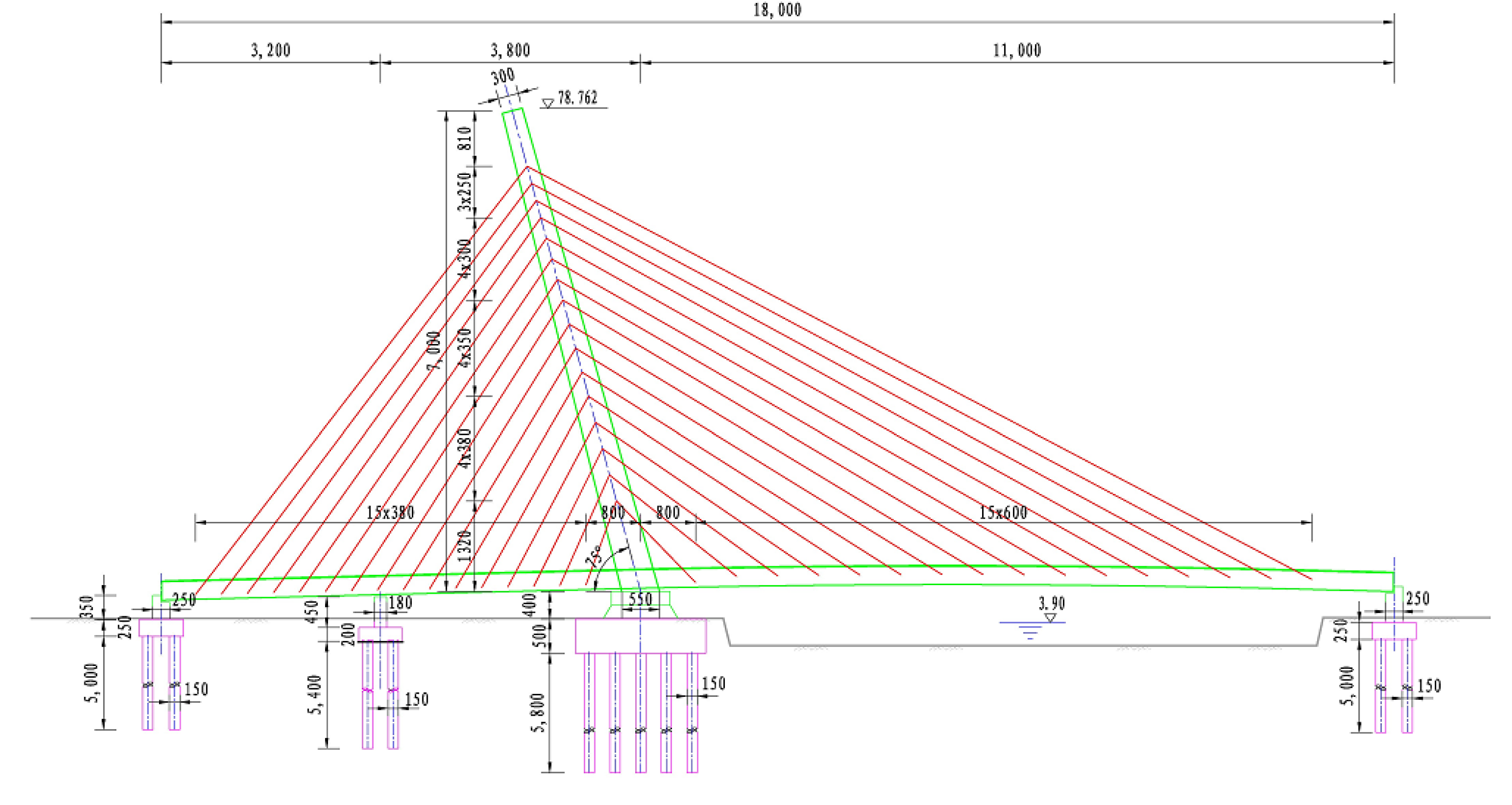
As shown in Figure 2, an FEM of the single tower cable-stayed bridge named “Guandu Bridge” is provided as an example to verify the proposed damage identification method. The main physical parameters of this bridge are listed in Table 1. The relations between the element numbers and the node numbers of this bridge are listed in Table 2.
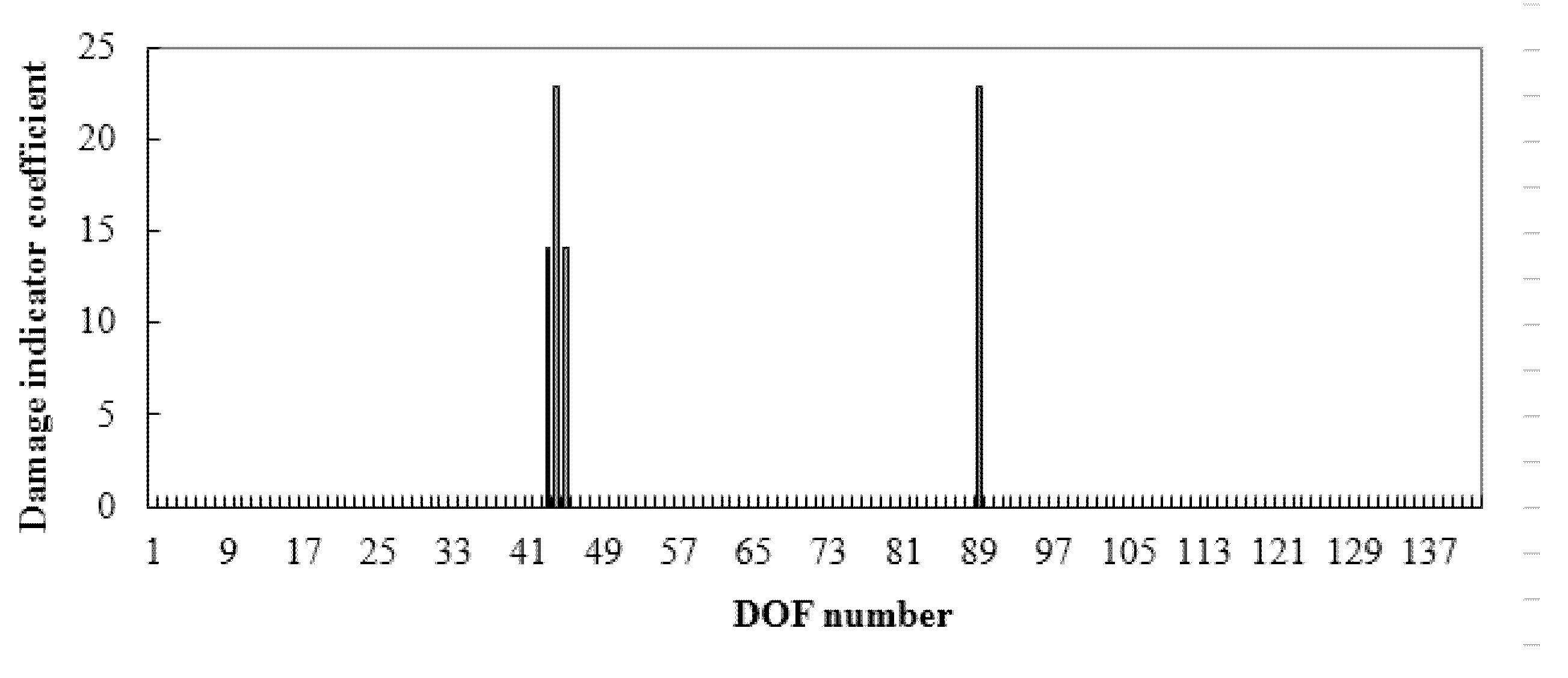
Two static loading modes with different loading positions were used to obtain the displacement data. The first static loading mode applied two vertical forces on the 67 and 70 DOFs. The second static loading mode applied two vertical forces on the 112 and 115 DOFs. Three damage conditions were simulated in this work. Damage condition 1 assumed a single damage appearing in cable element 31 (long cable) with a stiffness loss of 15%. Damage condition 2 assumed cable element 15 (short cable) was damaged with a stiffness reduction of 15%. Damage condition 3 assumed that cable elements 10 and 30 were both damaged at the same time with a stiffness reduction in both of 20%. For the first damage case, the proposed damage indicator vector γ is shown in Figure 3.
From Figure 3, DOFs 4, 5, 6, and 137 are the identified damaged DOFs, since their corresponding indicator coefficients were noticeably larger than the other coefficients. According to Table 1, cable 31 was the associated component for these damaged DOFs. By using Equation (19), the damage extent of cable 31 was obtained as α31 = 0.15.
For the second damage case, the calculated damage indicator vector is shown in Figure 4. It is clear from Figure 4 that DOFs 43, 44, 45, and 89 are the identified damaged DOFs, for their indicator coefficients were considerably larger than the other coefficients. According to Table 1, cable element 15 was the corresponding damaged element. The damage extent was calculated using Equation (19) to be α15 = 0.15.
For the third damage case, the calculated damage indicator vector is shown in Figure 5. It is clear from Figure 5 that DOFs 7, 8, 9, 28, 29, 30, 74, and 134 are the identified damaged DOFs, for their indicator coefficients were obviously larger than the other coefficients. According to Table 1, cable elements 10 and 30 were the corresponding damaged components. For this multiple-damage case, the damage extents were calculated using Equation (20) to be α10 = 0.2 and α30 = 0.2 for cables 10 and 30, respectively.
From the above results, it was shown that the proposed method had good identification accuracy for both short and long cable damage cases. The proposed method successfully determined the damaged cable location and extent, even if the static load was unknown.
Next, a comparative study is carried out on the calculation accuracy between the proposed method and the displacement sensitivity method. The displacement sensitivity method [39] is a damage assessment method to acquire damage extent through static displacement sensitivity analysis. The main formulas of the static sensitivity method are briefly reviewed as follows.
From Equations (1)–(3), one has the following formulas:
u = K 1 l
u d = K d 1 l = ( K Δ K ) 1 l
where the superscript −1 denotes the matrix inversion. Subtracting Equation (26) from (27) yields the following:
Δ u = u d u = [ ( K Δ K ) 1 K 1 ] l
where Δ u is the displacement change before and after damage. Using Neumann series expansion, Equation (28) can be approximated as the following:
Δ u = K 1 Δ K K 1 l
Substituting Equation (10) into (29) yields the following:
Δ u = j = 1 N α j s j
s j = ( K 1 K j K 1 ) l
where s j is the j th elementary displacement sensitivity. Equation (30) can be rewritten as the following:
Δ u = S ϑ
S = [ s 1 , s 2 , , s N ] , ϑ = ( α 1 , α 2 , , α N ) T
From Equation (32), the damage parameters can be calculated with the following:
ϑ = S + Δ u
where the superscript + denotes the Moore–Penrose inverse of a matrix.
Using the above displacement sensitivity method, the calculation results for the three damage cases of the numerical example are presented in Table 3.
From Table 3, one can see that the calculation results obtained by the proposed method are more accurate than those of the displacement sensitivity method. As stated before, the dynamic method is also often used to detect the damage in cables. From the existing literature, the static method usually has higher detection accuracy compared with the dynamic method, but the operation process is more complex and requires a longer time. Note that the proposed method is applied for the first time to cable damage identification by this numerical example. In future studies, it is necessary to carry out a comparative study between the proposed method and the dynamic method for cable damage detection.

4. Conclusions

Damage identification in cable force is of great significance to maintain the structural safety of cable-stayed bridges. The existing static methods for cable force damage identification generally require knowledge of an accurate magnitude of static force. This increases the test cost and time for static methods. To overcome this shortcoming, an improved residual force algorithm was proposed in this paper, which is independent of static load vector. By combining two different static loading modes, a new damage indicator vector was defined in the method for damage localization and quantification. Compared with existing static residual force methods, the outstanding advantage of the proposed algorithm is that the specific value of static load is not required in the damage identification process. The feasibility of the proposed method was verified by the example of a single tower cable-stayed bridge. Even if the static load is unknown, the proposed method can successfully identify the damages to cable forces. It was shown that the proposed method has good application prospects in engineering practice. The proposed method is also applicable to damage identification in other types of linear structures. More numerical and experimental studies should be carried out for applications of the proposed method in the future.

Author Contributions

Conceptualization, R.F. and W.W.; formal analysis, Q.Y.; writing—original draft preparation, Y.W. and Q.Y.; writing—review and editing, L.N. and P.J.; project administration, Q.B. All authors have read and agreed to the published version of the manuscript.

Funding

This research received no external funding.

Institutional Review Board Statement

Not applicable.

Informed Consent Statement

Not applicable.

Data Availability Statement

The data presented in this study are available on request from the corresponding author.

Conflicts of Interest

The authors declare no conflict of interest.

References

  1. Ko, J.M.; Sun, Z.G.; Ni, Y.Q. Multi-stage identification scheme for detecting damage in cable-stayed Kap-Shui-Mun Bridge. Eng. Struct. 2002, 24, 857–868. [Google Scholar] [CrossRef]
  2. Zhu, J.; Xiao, R. Damage identification of a large-span concrete cable-stayed bridge based on genetic algorithm. Front. Archit. Civ. Eng. China 2007, 1, 170–175. [Google Scholar] [CrossRef]
  3. Ni, Y.Q.; Zhou, H.F.; Chan, K.C.; Ko, J.M. Modal flexibility analysis of cable-stayed Ting Kau Bridge for damage identification. Comput.-Aided Civ. Infrastruct. Eng. 2008, 23, 223–236. [Google Scholar] [CrossRef]
  4. Hou, L.Q.; Zhao, X.F.; Han, R.C. Optimal sensor placement for stay cable damage identification of cable-stayed bridge under uncertainty. Int. J. Distrib. Sens. Netw. 2013, 9, 361594. [Google Scholar] [CrossRef]
  5. Mehrabi, A.B.; Telang, N.M. Cable-stayed bridge performance evaluation—Lessons from the field. In Proceedings of the 2003 ASCE Structures Congress, Seattle, WA, USA, 28 May–1 June 2003. [Google Scholar]
  6. Ho, H.N.; Kim, K.D.; Park, Y.S.; Young, S.P.; Jong, J.L. An efficient image-based damage detection for cable surface in cable-stayed bridges. Ndt E Int. 2013, 58, 18–23. [Google Scholar] [CrossRef]
  7. Mehrabi, A.B. In-service evaluation of cable-stayed bridges, overview of available methods and findings. J. Bridge Eng. 2006, 11, 716–724. [Google Scholar] [CrossRef]
  8. Liu, X.; Xiao, J.; Wu, B.; He, C.F. A novel sensor to measure the biased pulse magnetic response in steel stay cable for the detection of surface and internal flaws. Sens. Actuators A Phys. 2018, 269, 218–226. [Google Scholar] [CrossRef]
  9. Zhang, S.; Shen, R.; Dai., K.; Wang, L.; Roeck, G. A methodology for cable damage identification based on wave decomposition. J. Sound Vib. 2019, 442, 527–551. [Google Scholar] [CrossRef]
  10. Kildashti, K.; Alamdari, M.M.; Kim, C.W.; Gao, W.; Samali, B. Drive-by-bridge inspection for damage identification in a cable-stayed bridge: Numerical investigations. Eng. Struct. 2020, 223, 110891. [Google Scholar] [CrossRef]
  11. Huang, J.; Li, D.; Li, H.; Song, G.; Liang, Y. Damage identification of a large cable-stayed bridge with novel cointegrated Kalman filter method under changing environments. Struct. Control Health Monit. 2018, 25, e2152. [Google Scholar] [CrossRef]
  12. An, Y.; Chatzi, E.; Sim, S.H.; Laflamme, S.; Blachowski, B.; Ou, J. Recent progress and future trends on damage identification methods for bridge structures. Struct. Control Health Monit. 2019, 26, e2416. [Google Scholar] [CrossRef]
  13. Radzieński, M.; Krawczuk, M.; Palacz, M. Improvement of damage detection methods based on experimental modal parameters. Mech. Syst. Signal Process. 2011, 25, 2169–2190. [Google Scholar] [CrossRef]
  14. Kopsaftopoulos, F.P.; Fassois, S.D. A functional model based statistical time series method for vibration based damage detection, localization, and magnitude estimation. Mech. Syst. Signal Processing 2013, 39, 143–161. [Google Scholar] [CrossRef]
  15. Sung, S.H.; Jung, H.J.; Jung, H.Y. Damage detection for beam-like structures using the normalized curvature of a uniform load surface. J. Sound Vib. 2013, 332, 1501–1519. [Google Scholar] [CrossRef]
  16. Xiang, J.; Matsumoto, T.; Wang, Y.; Jiang, Z. Detect damages in conical shells using curvature mode shape and wavelet finite element method. Int. J. Mech. Sci. 2013, 66, 83–93. [Google Scholar] [CrossRef]
  17. Xu, Z.D.; Liu, M.; Wu, Z.; Zeng, X. Energy damage detection strategy based on strain responses for long-span bridge structures. J. Bridge Eng. 2011, 16, 644–652. [Google Scholar] [CrossRef]
  18. Yi, T.H.; Li, H.N.; Sun, H.M. Multi-stage structural damage diagnosis method based on “energy-damage” theory. Smart Struct. Syst. 2013, 12, 345–361. [Google Scholar] [CrossRef]
  19. Cha, Y.J.; Buyukozturk, O. Structural damage detection using modal strain energy and hybrid multiobjective optimization. Comput. Aided Civ. Infrastruct. Eng. 2015, 30, 347–358. [Google Scholar] [CrossRef]
  20. Khorram, A.; Bakhtiari-Nejad, F.; Rezaeian, M. Comparison studies between two wavelet based crack detection methods of a beam subjected to a moving load. Int. J. Eng. Sci. 2012, 51, 204–215. [Google Scholar] [CrossRef]
  21. Roveri, N.; Carcaterra, A. Damage detection in structures under traveling loads by Hilbert–Huang transform. Mech. Syst. Signal Process. 2012, 28, 128–144. [Google Scholar] [CrossRef]
  22. Cavadas, F.; Smith, I.F.C.; Figueiras, J. Damage detection using data-driven methods applied to moving-load responses. Mech. Syst. Signal Processing 2013, 39, 409–425. [Google Scholar] [CrossRef] [Green Version]
  23. Chung, J.L.; Yu, T.H. Vibration analysis of an inhomogeneous string for damage detection by wavelet transform. Int. J. Mech. Sci. 2002, 44, 745–754. [Google Scholar]
  24. Lepidi, M.; Gattulli, V.; Vestroni, F. Damage identification in elastic suspended cables through frequency measurement. J. Vib. Control 2009, 15, 867–896. [Google Scholar] [CrossRef]
  25. Wang, X.; Hu, N.; Fukunaga, H.; Yao, Z. Structural damage identification using static test data and changes in frequencies. Eng. Struct. 2001, 23, 610–621. [Google Scholar] [CrossRef]
  26. Sanayei, M.; Onipede, O. Assessment of structures using static test data. AIAA J. 1991, 29, 1156–1179. [Google Scholar] [CrossRef]
  27. Banan, M.R.; Banna, M.R.; Hjelmstad, K.D. Parameter estimation of structures from static response, Ⅰ: Computational aspects. J. Struct. Eng. 1994, 120, 3243–3258. [Google Scholar] [CrossRef]
  28. Banan, M.R.; Banna, M.R.; Hjelmstad, K.D. Parameter estimation of structures from static response, Ⅱ: Numerical simulation studies. J. Struct. Eng. 1994, 120, 3259–3283. [Google Scholar] [CrossRef]
  29. Hjelmstad, K.D.; Shin, S. Damage detection and assessment of structures from static response. J. Eng. Mech. 1997, 123, 568–576. [Google Scholar] [CrossRef]
  30. Chou, J.H.; Ghaboussi, J. Genetic algorithm in structural damage detection. Comput. Struct. 2001, 79, 1335–1353. [Google Scholar] [CrossRef]
  31. Bakhtiari-Nejad, F.; Rahai, A.; Esfandiari, A. A structural damage detection method using static noisy data. Eng. Struct. 2005, 27, 1784–1793. [Google Scholar] [CrossRef]
  32. Chen, X.Z.; Zhu, H.P.; Chen, C.Y. Structural damage identification using test static data based on grey system theory. J. Zhejiang Univ. Sci. 2005, 6A, 790–796. [Google Scholar] [CrossRef]
  33. Kouchmeshky, B.; Aquino, W.; Bongard, J.C.; Lipson, H. Co-evolutionary algorithm for structural damage identification using minimal physical testing. Int. J. Numer. Methods Eng. 2007, 69, 1085–1107. [Google Scholar] [CrossRef] [Green Version]
  34. Yang, Q.W.; Liu, J.K.; Sun, B.X.; Liang, C.F. Damage localization for beam structure by moving load. Adv. Mech. Eng. 2017, 9, 1–6. [Google Scholar] [CrossRef] [Green Version]
  35. Hua, X.G.; Ni, Y.Q.; Chen, Z.Q.; Ko, J.M. Structural damage detection of cable-stayed bridges using changes in cable forces and model updating. J. Struct. Eng. 2009, 135, 1093–1106. [Google Scholar] [CrossRef]
  36. Lin, S.W.; Yi, T.H.; Li, H.N.; Ren, L. Damage detection in the cable structures of a bridge using the virtual distortion method. J. Bridge Eng. 2017, 22, 04017039. [Google Scholar] [CrossRef]
  37. Yang, Q.W.; Zhou, C.; Li, C.H.; Luo, S. Structural damage assessment based on static residual force vector. Chin. J. Comput. Mech. 2021, 38, 625–630. [Google Scholar]
  38. Lepidi, M.; Gattulli, V.; Vestroni, F. Static and dynamic response of elastic suspended cables with damage. Int. J. Solids Struct. 2007, 44, 8194–8212. [Google Scholar] [CrossRef] [Green Version]
  39. Jin, W.M.; Yang, Q.W.; Zhao, W. Damage diagnosis by an improved static-based method. J. Mech. Strength 2012, 34, 190–193. [Google Scholar]
Figure 1. The flowchart of the whole technique.
Applsci 12 02945 g001
Figure 2. A single tower cable-stayed bridge.
Applsci 12 02945 g002
Figure 3. Damage indicator vector when long cable 31 was damaged.
Applsci 12 02945 g003
Figure 4. Damage indicator vector when short cable 15 was damaged.
Applsci 12 02945 g004
Figure 5. Damage indicator vector when cables 10 and 30 were damaged.
Applsci 12 02945 g005
Table 1. Physical parameters of the single tower cable-stayed bridge.
ElementsElastic ModulusDensityCross Sectional AreaMoment of Inertia
Cable200 GPa7800 kg/m34.657 × 10−3 m2/
Pylon200 GPa7800 kg/m30.31 m20.437
Box girder200 GPa7800 kg/m30.75 m21.26
Table 2. Cable elements with corresponding nodes and DOFs.
Cable Element Number
(From Left to Right)
Corresponding NodesCorresponding DOFs
11, 171, 2, 3, 49, 50
22, 184, 5, 6, 51, 52
33, 197, 8, 9, 53, 54, 55
44, 2010, 11, 12, 56, 57, 58
55, 2113, 14, 15, 59, 60, 61
66, 2216, 17, 18, 62, 63, 64
77, 2319, 20, 21, 65, 66, 67
88, 2422, 23, 24, 68, 69, 70
99, 2525, 26, 27, 71, 72, 73
1010, 2628, 29, 30, 74, 75, 76
1111, 2731, 32, 33, 77, 78, 79
1212, 2834, 35, 36, 80, 81, 82
1313, 2937, 38, 39, 83, 84, 85
1414, 3040, 41, 42, 86, 87, 88
1515, 3143, 44, 45, 88, 89, 90
1616, 3246, 47, 48, 92, 93, 94
1716, 3346, 47, 48, 95, 96, 97
1815, 3443, 44, 45, 98, 99, 100
1914, 3540, 41, 41, 101, 102, 103
2013, 3637, 38, 39, 104, 105, 106
2112, 3734, 35, 36, 107, 108, 109
2211, 3831, 32, 33, 110, 111, 112
2310, 3928, 29, 30, 113, 114, 115
249, 4025, 26, 27, 116, 117, 118
258, 4122, 23, 24, 119, 120, 121
267, 4219, 20, 21, 122, 123, 124
276, 4316, 17, 18, 125, 126, 127
285, 4413, 14, 15, 128, 129, 130
294, 4510, 11, 12, 131, 132, 133
303, 467, 8, 9, 134, 135, 136
312, 474, 5, 6, 137, 138, 139
321, 481, 2, 3, 140, 141, 142
Table 3. The comparison of the calculation results obtained by both the displacement sensitivity method and the proposed method.
Damage CasesTrue ValuesCalculation Results of the
Displacement Sensitivity Method
Calculation Results of the Proposed Method
1α31 = 0.15α31 = 0.1518α31 = 0.15
2α15 = 0.15α15 = 0.1518α15 = 0.15
3α10 = 0.2 and α30 = 0.2α10 = 0.2033 and α30 = 0.2023α10 = 0.2 and α30 = 0.2
Publisher’s Note: MDPI stays neutral with regard to jurisdictional claims in published maps and institutional affiliations.