Article

Detection and Analysis of Partial Discharges in Oil-Immersed Power Transformers Using Low-Cost Acoustic Sensors

by
Hamidreza Besharatifard
1,
Saeed Hasanzadeh
1,*,
Ehsan Heydarian-Forushani
1,
Hassan Haes Alhelou
2,* and
Pierluigi Siano
3,4,*
1
Department of Electrical and Computer Engineering, Qom University of Technology, Qom 1519-37195, Iran
2
Department of Electrical Power Engineering, Faculty of Mechanical and Electrical Engineering, Tishreen University, Latakia 2230, Syria
3
Department of Management & Innovation Systems, University of Salerno, 84084 Fisciano, Italy
4
Department of Electrical and Electronic Engineering Science, University of Johannesburg, Johannesburg 2006, South Africa
*
Authors to whom correspondence should be addressed.
Appl. Sci. 2022, 12(6), 3010; https://doi.org/10.3390/app12063010
Submission received: 22 February 2022 / Revised: 12 March 2022 / Accepted: 14 March 2022 / Published: 16 March 2022
(This article belongs to the Section Energy Science and Technology)

Abstract

:
Partial Discharge (PD) is one of the symptoms of an electrical insulation problem, and its permanence can lead to the complete deterioration of the electrical insulation in high-voltage equipment such as power transformers. The acoustic emission (AE) method is a well-known technique used to detect and localize PD activity inside oil-filled transformers. However, the commercially available monitoring systems based on acoustic sensors still have a high cost. This paper analyses the ability of low-cost piezoelectric sensors to identify PDs within oil-filled power transformers. To this end, two types of low-cost piezoelectric sensors were fully investigated using time-domain, frequency-domain, and time-frequency analysis, separately. Thereafter, the effectiveness of these sensors for PD detection and monitoring was studied. A three-phase distribution transformer filled with oil was examined. PDs were produced inside an oil-immersed transformer by applying a high voltage over two copper electrodes, and the AE sensors were coupled to the housing of the transformer. By extracting typical features from the AE signals, the PD signals were differentiated from on-site noise and interference. The AE signals were analyzed using acoustic signal metrics such as peak value, energy criterion, and other statistical parameters. The obtained results indicated that the used low-cost piezoelectric sensors have the capability of PD monitoring within power transformers.

1. Introduction

Power transformers are considered important equipment in power systems. Based on the transformer failure statistics in CIGRE A2.37, the most common cause of failure in power transformers is represented by winding and insulation faults [1]. Therefore, the online monitoring of power transformer insulation systems could avoid failures and the resulting catastrophic chain of events that increase destruction. One of the best solutions to monitor transformers is partial discharge (PD) measurement.
PDs that occur in high-voltage equipment are electrical discharges that happen at points with poor insulation or a high electrical field and only partially bridge the insulation between the conductors; they may or may not occur adjacent to a conductor [2]. The PD phenomenon has several effects, such as electrical, electromagnetic, chemical, acoustic, and optical effects, and can be detected using specific sensors. In some studies, High-Frequency Current Transformers (HFCT), High-Voltage Coupling Capacitors, Ultra-High-Frequency Antennas (UHF), and acoustic sensors have been used for PD detection and measurement [3,4,5,6,7,8,9,10,11,12]. Based on the type of equipment that is monitored, the choice of the appropriate method can be crucial for detecting faults and avoiding false alarms. The method based on acoustic wave propagation, also known as the acoustic emission (AE) method, is a non-destructive testing (NDT) method and has the advantage of being non-invasive to the monitored equipment. AE can also be used for the localization of faults inside transformers. An advantage of acoustic detection with respect to electrical methods is its immunity to on-site electromagnetic interference (EMI). Immunity to EMI makes acoustic detection ideal for online PD detection and monitoring. Its better signal-to-noise ratio (SNR) for the acoustic signal leads to fewer false alarms.
The AE method is based on detecting transient elastic waves generated by a rapid release of energy caused by the PD. The spectrum of the resulting acoustic signal can extend to several MHz [13]. These acoustic signals are detected by AE sensors located on the external wall of the transformer. However, the main disadvantage of this method is the high cost of commercial AE sensors (from 100 to 1000 dollars [14]), especially when multiple sensors are required. In this context, the objective of this paper is to present a low-cost, non-invasive method for PD detection in power transformers by applying low-cost piezoelectric diaphragms, commonly known as buzzers. This study uses two low-cost piezoelectric sensors, the lead zirconate titanate (PZT) and the microfiber composite (MFC). Several studies have previously used these sensors for PD detection and measurement. In ref. [14], a comparative study between the low-cost piezoelectric diaphragm (PZT) and a commercial AE sensor (RS15I-AST) was done. A comparison of the responses in the time and frequency domains of both sensors was carried out. The experimental results indicated that the proposed piezoelectric sensors had great potential for detecting acoustic waves generated by PDs in insulation oil. In ref. [15], a microfiber composite (MFC) and the AE sensor (RS15I-AST) were studied through parameters such as root mean square (RMS), energy criterion, Akaike criterion, power spectral density (PSD), and correlation. Most articles that showed the effectiveness of these low-cost piezoelectric sensors only analyzed the signals in the frequency-domain mode, which may hide useful information such as repetitive faults [16,17]. In ref. [18], a comparative study between the low-cost PZT and the MFC was performed only through time-frequency analysis and RMS of the signals.
The purpose of this paper was to conduct an in-depth analysis of the PD phenomenon through a comparative evaluation of captured PD signals from two low-cost piezoelectric sensors, via time-domain, frequency-domain, time-frequency, and statistical analysis. Based on the AE method, we studied the ability of two low-cost piezoelectric sensors attached to the external wall of a transformer to detect the elastic waves emitted by PDs, allowing non-invasive PD monitoring. Online continuous monitoring for defect prevention contributed decisively to an improvement in the quality of the electricity supply. Moreover, considerable material losses were prevented, improving the equipment’s reliability and safety. First, the signals from acoustical measurements were digitally processed in the time-domain mode; this type of signal processing is commonly used in all commercially available equipment for PD analysis. When the acoustic signal crosses a threshold, the monitoring system reacts and measures certain typical AE parameters such as amplitude, rise time, duration, and oscillations (also called counts). A good SNR is necessary for this analysis to obtain a correct response. Otherwise, the system is less effective and could lead to false alarms. The better the SNR, the more sensitive the apparatus. Data from a PD’s acoustic signal allows for performing a more in-depth analysis in the frequency domain using the fast Fourier transform (FFT), power spectral density (PSD), and a spectrogram that is a time-frequency analysis. To better understand the characteristics of the measured acoustic signals, this study also used the energy criterion, RMS, and other statistical parameters, such as standard deviation (STD), skewness, and kurtosis. These parameters were very helpful for a proper analysis of the sensors to detect and measure the PD phenomenon.
This paper is organized as follows: Section 2 describes the low-cost acoustic sensors for PD detection and the experimental setup and present the time-domain, frequency-domain, and time-frequency analysis. Additional statistical parameters are presented and discussed in Section 3. Finally, Section 4 concludes the paper.

2. Partial Discharge Detection Using the AE Method and Signal Processing Analysis

2.1. Piezoelectric Sensors

The piezoelectric effect occurs in materials that produce an output voltage when subjected to mechanical stress. The reverse effect also occurs, so that a mechanical deformation arises by applying an electrical voltage between two sides of the piezoelectric material [14]. The piezoelectric transducers shown in Figure 1 are AE sensors available at low cost, ranging from a few cents to a few dollars, depending on the size and the manufacturer. Piezoelectric diaphragms are sound components with a simple structure consisting of a piezoelectric ceramic disk adhered to a brass plate, as shown in Figure 1a. The ceramic is coated with a metal film, which serves as an electrode [14]. The LDT1-028K is a piezoelectric sensor that detects physical phenomena such as vibration or impact (Figure 1b). The piezo film element is laminated to a sheet of polyester (Mylar) and produces a useable electrical signal output when forces are applied to the sensing area. This study compared two types of low-cost piezoelectric transducers, the microfiber composite (MFC) LDT1-028K type and the lead zirconate titanate (PZT). These sensors should be installed on the surface using an acoustic couplant. An acoustic couplant is a material used at the structure-to-sensor interface to improve the transmission of acoustic energy across the interface during AE monitoring.

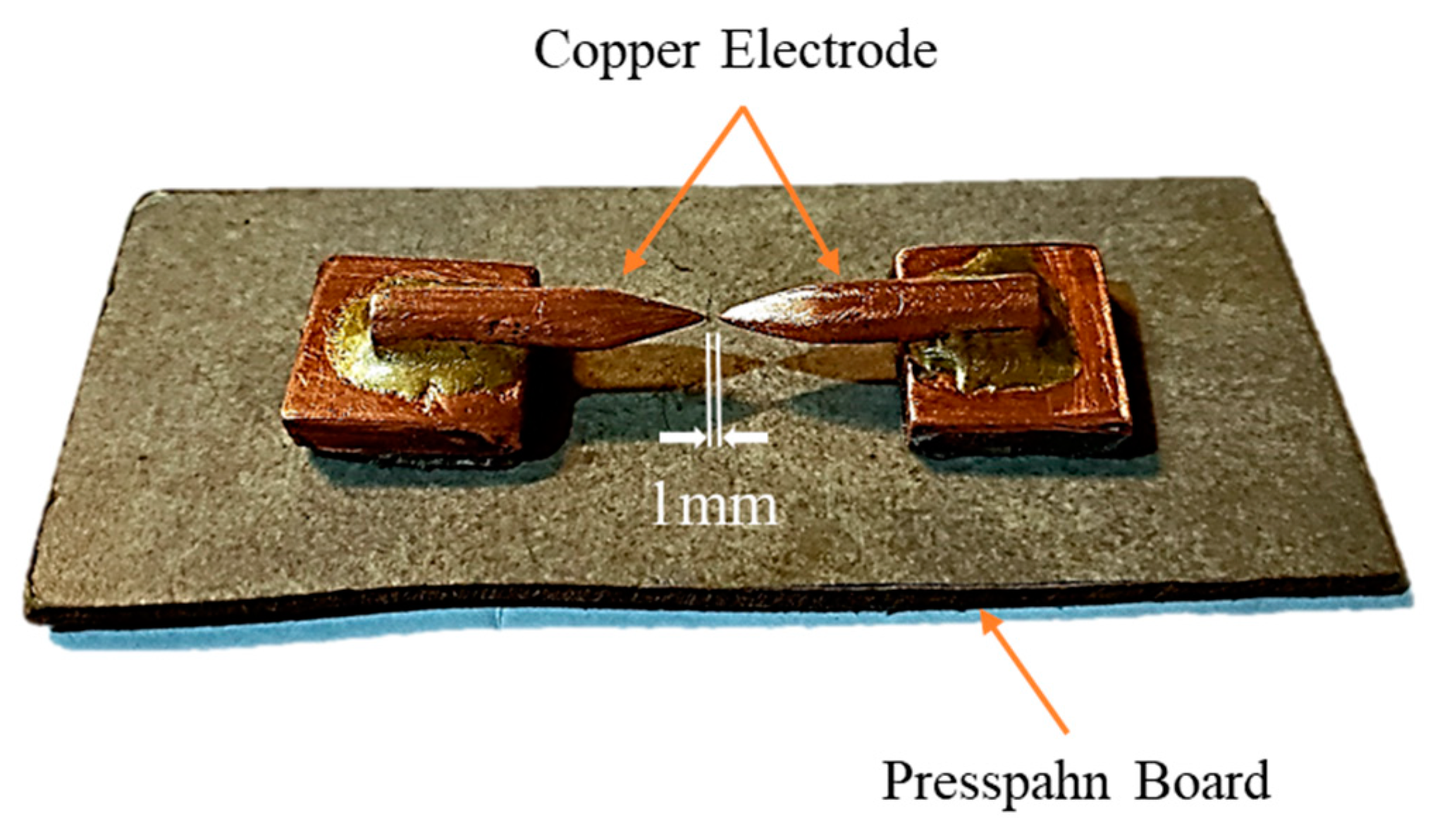
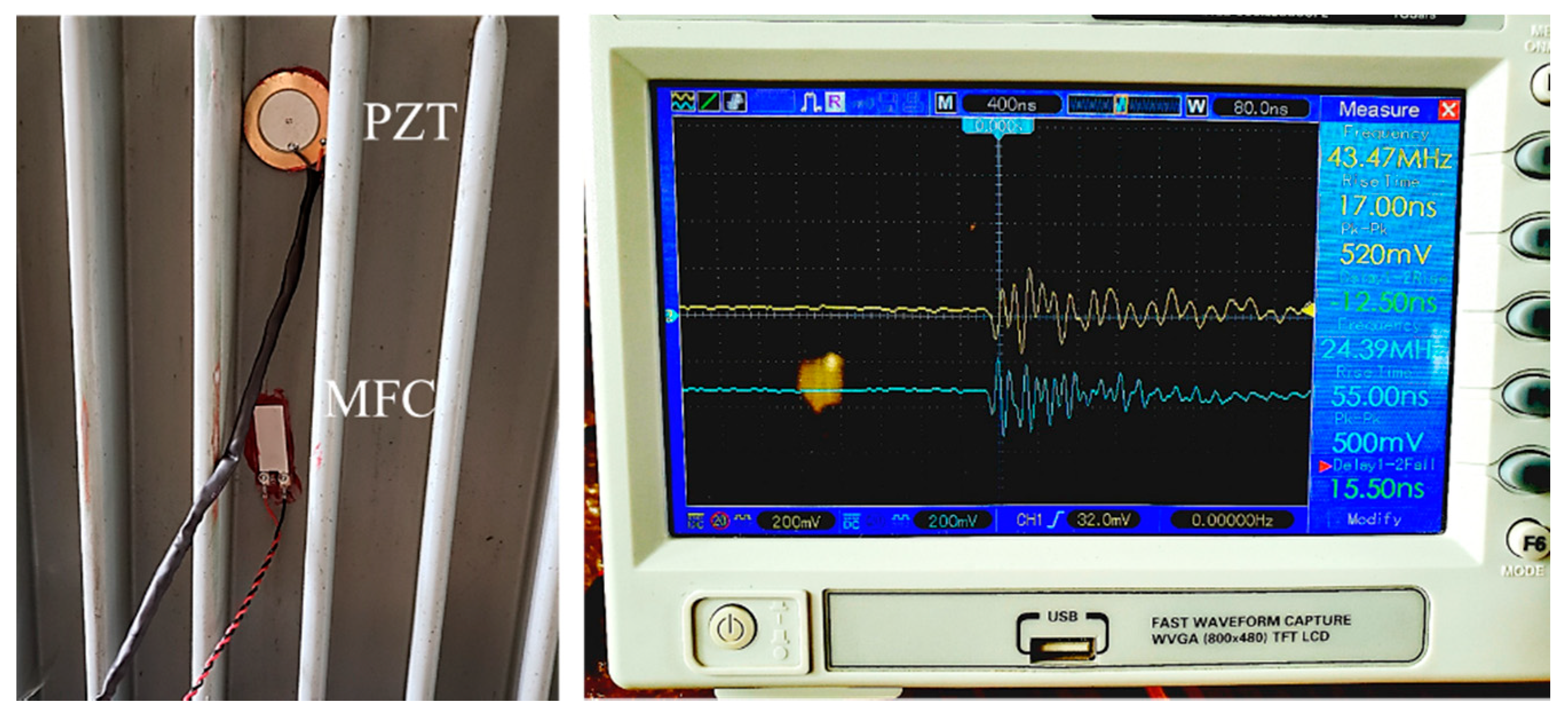
2.2. Experimental Setup

The MFC-LDT1-028K and PZT-7BB-35-3 sensors were fixed to a three-phase distribution transformer wall (Figure 2) using lithium grease gel to capture the AE signals emitted by PDs. Figure 3 shows two copper electrodes placed in front of each other with a 1 mm gap between them to form a needle–needle configuration (PD source). The PD source was placed inside the transformer, and a PD was generated by applying 9 kV between the electrodes with a high-voltage transformer. The acoustic signals sensed by the piezoelectric sensors (Figure 4) were transferred to an oscilloscope via twisted pair cables to avoid EMI and other environmental noise. An oscilloscope captured the data, the acquisition rate was set at 500 MSa/s, and no filter or amplifier was used in the circuit. As discussed in the next sections, several routines for signal processing analysis were developed in MATLAB.

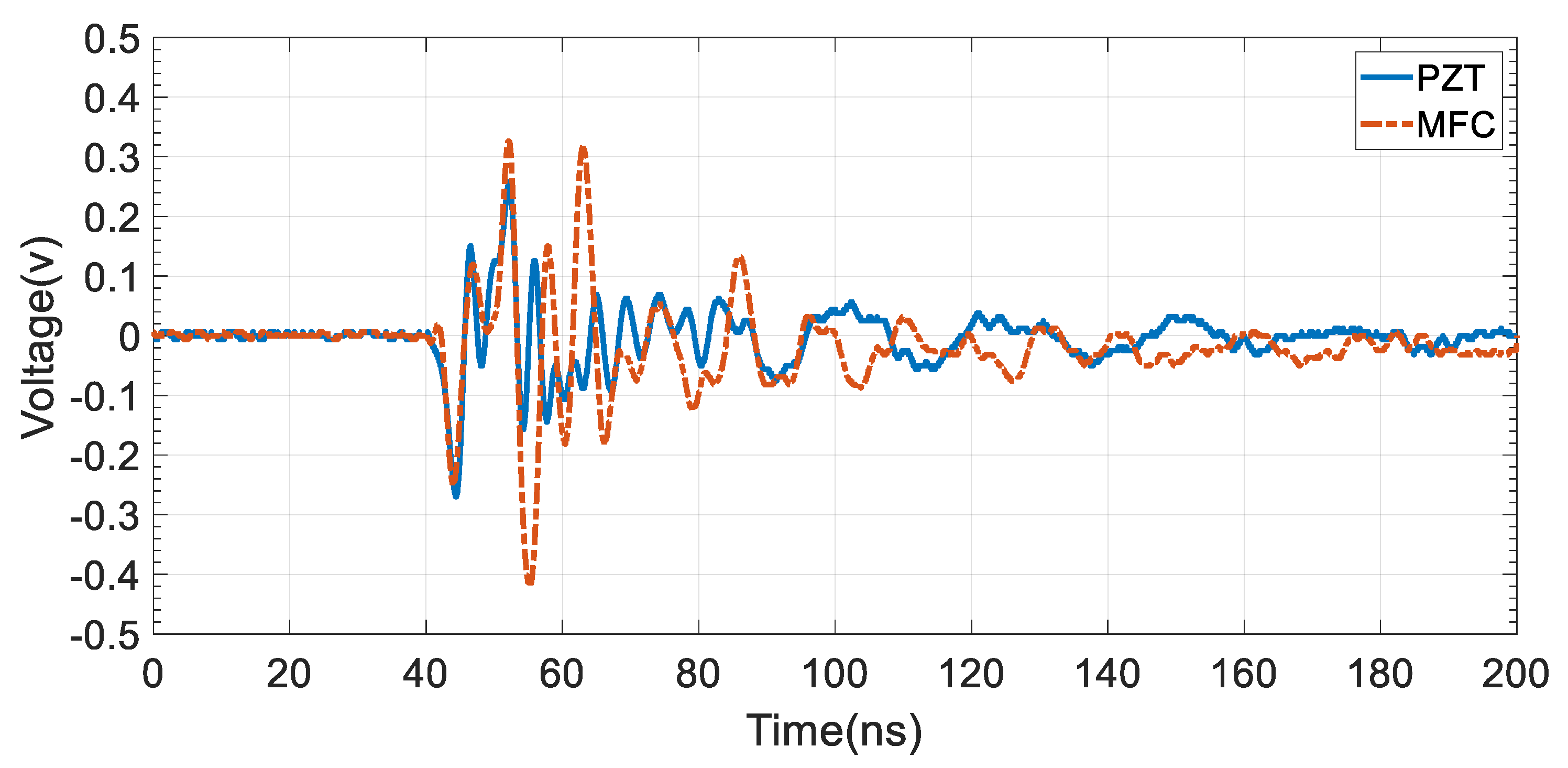
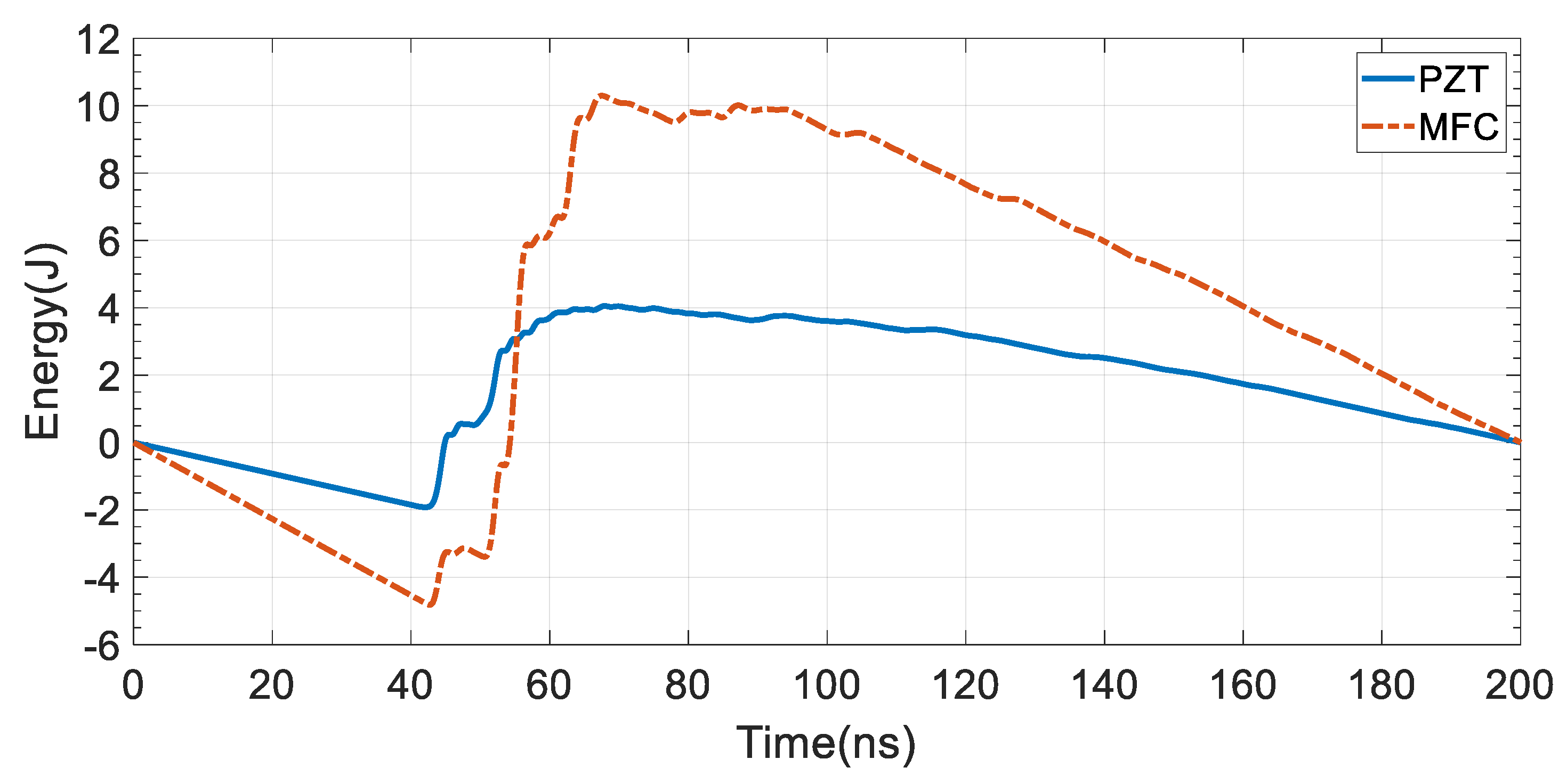
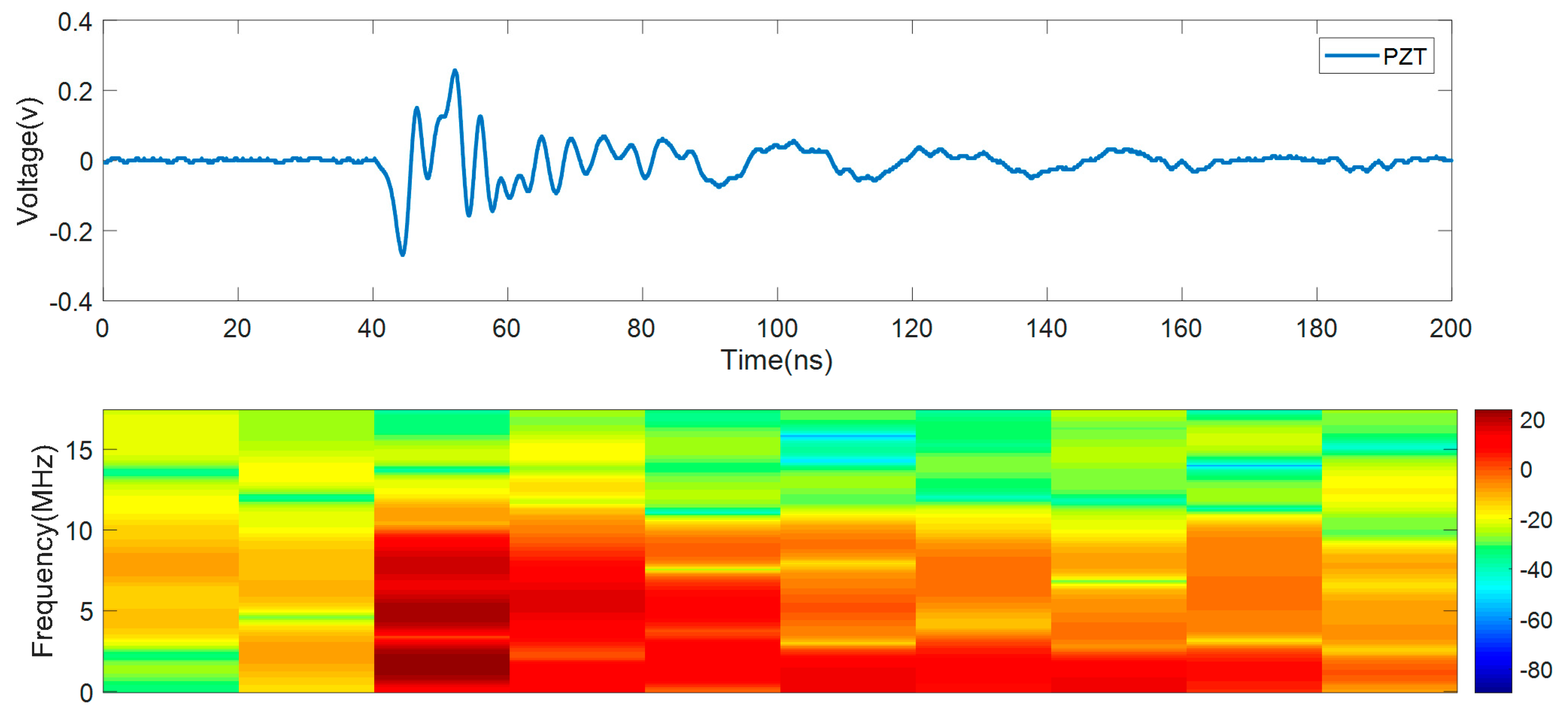
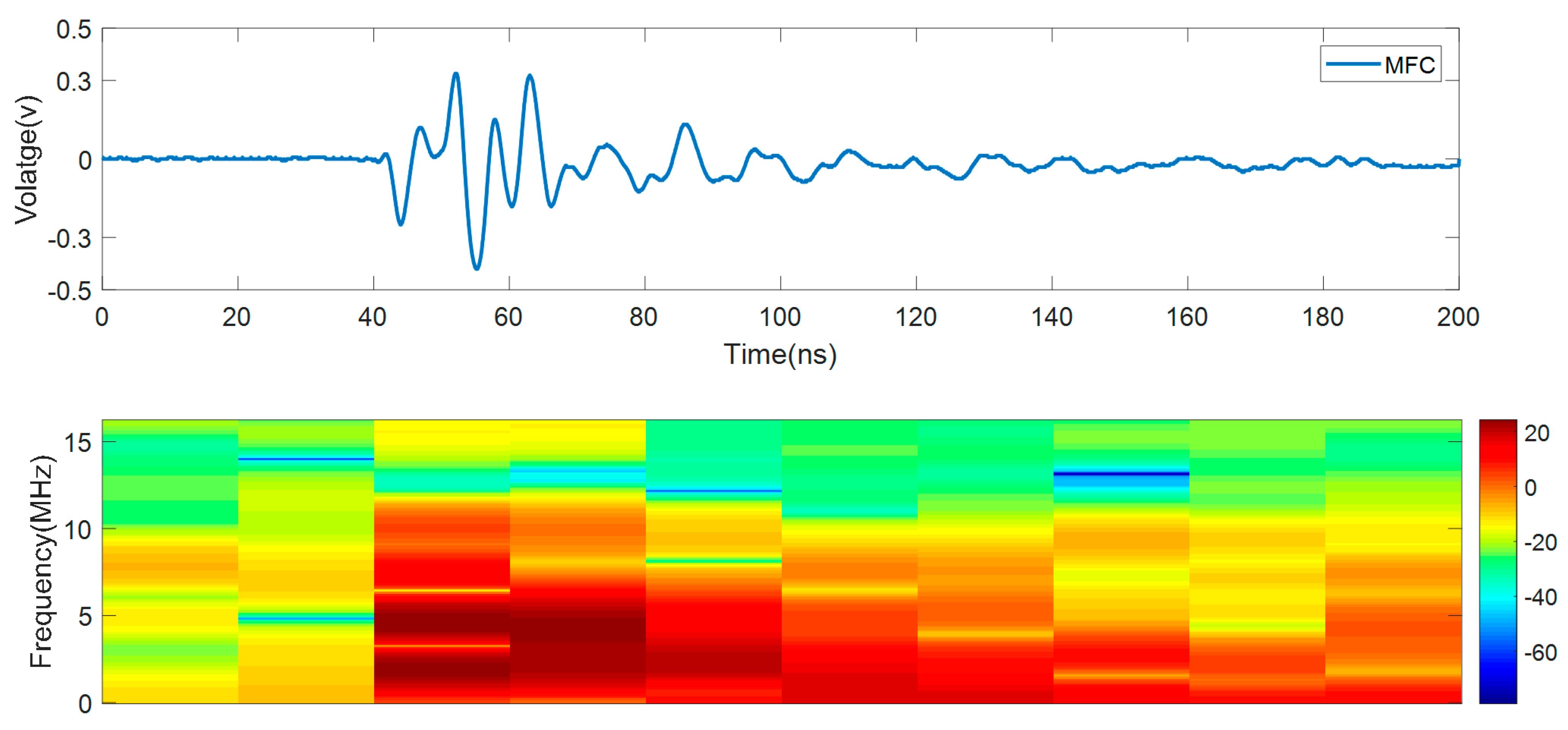
2.3. Time-Domain Analysis

AE is based on the detection of transient elastic waves generated by a rapid release of energy from localized sources inside a material. When applied to power transformers, these transient waves (acoustic emissions) are produced by faults inside the unit. These signals were detected by the piezoelectric sensors placed on the transformer’s tank, and all data were collected and stored by an oscilloscope. Most articles that show the effectiveness of these low-cost piezoelectric sensors analyzed the signals only in the frequency-domain mode, which may hide useful information such as repetitive faults [16,17]. Figure 5 shows the waveforms from acoustic sensors mounted on the outside of the transformer tank. Some of the features extracted were amplitude (volt), duration (nanoseconds), rise time (nanosecond), and counts, which are shown in detail for the PZT sensor in Figure 6 and for both sensors in Table 1. To understand whether an AE signal is a PD, factors such as burst length, movement of the AE signal relative to the excitation frequency, and rise time of the first oscillation that crosses the threshold are considered. The number of counts is usually higher when an AE signal is created by transient or environmental noises. The duration of the signal is another important factor that can help separate PD from on-site noises; for example, for a PD with the dominant frequency of 20 kHz, the duration of the acoustic PD signal is around 200 µs [13]. PDs monitored by conventional electrical methods use a threshold to predict severe activity. This level is generally from about 300 pC to 500 pC [13].
There is no similar threshold for acoustic systems because of variations in the acoustic signal caused by distance and interfering materials. A strong signal buried deep within a winding may be very weak by the time it reaches the acoustic sensor. Differences in amplifier gain settings also cause differences in magnitude [13]. If these points are not taken into account, this method could lead to errors or false alarms. Another usage of the time-domain analysis is in the comparison of sensors’ performance and characteristics. MFC has a higher amplitude because of its better sensitivity. Parameters such as rise time and duration can also help determine a sensor’s characteristics. In Figure 5, by comparing these two sensors’ responses for a fast edge pulse (PD), it is shown that the captured AE signal by MFC had a faster rise time and a lower duration. Therefore, it can be concluded that it follows a fast vibration better than the PZT sensor. The PD source was placed between these two sensors at equal distance, so the difference between the captured AE signals was due to their frequency response (Figure 5 and Table 1). Therefore, this analysis is crucial for differentiating PD signals from on-site noises and comparing sensors characteristics. These analyses were also confirmed by the results found in the frequency-domain and the statistical analysis presented in the next sections that show the complementary nature of these different types of analysis.
The time of arrival of a PD signal to the sensors is another parameter that can be useful in AE analysis, especially for PD localization applications. A major error in PD localization is due to the time of arrival or the time delay calculation. Because of noise and initial oscillation, the exact time of arrival of an AE signal is difficult to obtain directly from the time-domain of the signal. The time of arrival (TOA) could be calculated based on the minimum point of a signal energy plot (Figure 7). The total energy of the signal, SN, and the “S” parameter are given by [19]:
s N = i = 1 N x 2 ( i )
S = i = 1 n x 2 ( i ) n s N N
where S is the signal energy, n is the number of samples up to which the energy is calculated, and N is the total number of data points in the signal; x ( i ) is the value of each data point.
In Figure 7, it can be seen that both plots have almost the same trend, and the only difference is the amplitude of the signals. TOA can be achieved by finding the minimum of the signal energy curve, which for both sensors, was 42 ns. Signal analysis in the time domain does not give any information about PD frequencies, so it is not enough to thoroughly analyze the signal. To better understand PD aspects, acoustic signals that have been analyzed in the frequency-domain mode are discussed in the next section.

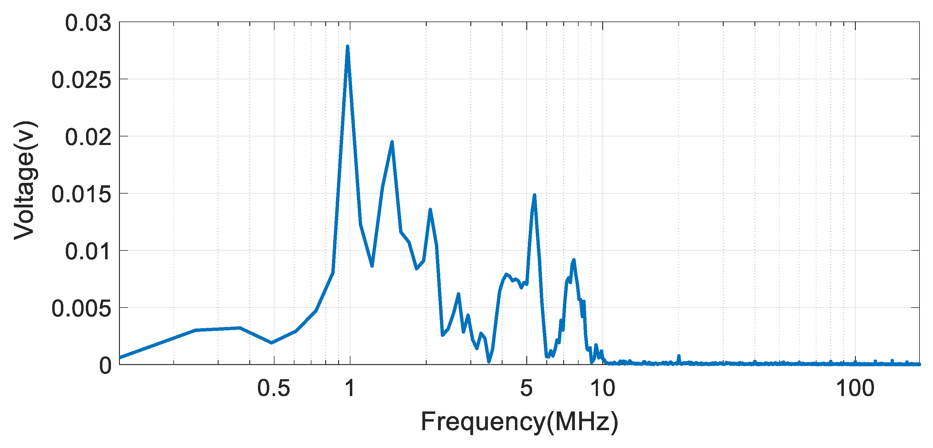
2.4. Frequency-Domain Analysis

Fast Fourier transform (FFT) is the first algorithm used to analyze signals in the frequency domain. Using FFT, vibration signals in the time domain are transmitted to the frequency domain. In this way, the dominant vibrational frequencies of the acoustic signals are identified. The FFT of acoustic signals is shown for the PZT and MFC sensors in Figure 8 and Figure 9, respectively. In Figure 8 and Figure 9, the x-axis reports the dominant frequencies, and the y-axis reports the values of the spectrum for the PD’s acoustic signals. Any frequency whose spectrum values have a peak is called a dominant frequency. For the PZT sensor, the dominant frequency was around 1 MHz and for the MFC sensor, the dominant frequency was around 2 MHz, as shown in Figure 8 and Figure 9, respectively. The center point of the two copper electrodes (PD source) was placed in a way that its distance to the sensors was almost equal. With the path of the signal to the sensor being the same, the sensors captured the same signal that was the PD signal generated by the PD source (acting as a fast edge signal generator). It can be concluded that the differences in the amplitude of FFTs were due to the sensitivity and frequency responses of the sensors; therefore, the PZT sensor had higher sensitivity than the MFC to frequencies over 5 MHz, and the MFC sensor was more sensitive to frequencies below 500 kHz.
The secondary processing of the FFT signals was performed by power spectral density (PSD) analysis. PSD can be calculated by dividing the square of the spectrum values by the frequency of that spectrum. With this method, high frequencies have a lower PSD value. The spectrum of acoustic signals generated by PD could extend up to a few MHz, so it is reliable to eliminate the higher frequencies to reject noise. This method could be useful when the signal has a low SNR and it is difficult to find dominant frequencies using the FFT method. The PSD of the signals is shown in Figure 10. For the PZT sensor, the peak wave frequency was 0.9766 MHz, and for the MFC sensor, the frequency of the peak wave was 2.075 MHz.
In the monitoring system of transformers, transient noise (rain, wind, etc.), Barkhausen noise, and electromagnetic interference can affect the frequency analysis, so if the signals are only analyzed in the frequency-domain mode, this can lead to wrong conclusions. The Fourier transform and power spectral density do not provide any information about when the dominant frequencies occur. Therefore, for signal analysis, a method should be used that provides frequency information in addition to time information of the PD phenomenon.

2.5. Time-Frequency Analysis

Short-Time Fourier transform (STFT) is a method that has been used to analyze signals in the time-frequency domain. Using this method, it is possible to determine when a phenomenon occurred as well as its frequency characteristics. This is feasible by windowing the main signal into smaller time windows and then using the Fourier transform algorithm for each of these windows. Thus, the STFT can be defined by [20]:
S T F T ( t , ω ) = + h ( u ) f ( t + u ) e j ω u d u
where f ( t ) is a given signal in the time domain, t is the time, ω the frequency, and h ( u ) the temporal window function such as rectangular, Gaussian, Blackman, Hanning, Hamming, Kaiser, etc. In this method, the signal should break into signals so small that can be assumed to be stable. The dominant frequencies in each part of the mother signal can be achieved by performing the Fourier transform. Figure 11 and Figure 12 are the spectrograms of the acoustic signals captured by the PZT and MFC sensors. These 3-D graphs show three parameters, frequency (y-axis), time (x-axis), and power spectrum by colored map. The time-domain of the signals are shown above the spectrogram of the signals for a better understanding. The occurrence of the defect can be seen from the spectrogram diagram. Before 40 ns and after 140 ns, the power spectrum has low amplitude, indicating that the system is in steady-state mode and there is no disturbance or defect. A sudden increase in the power spectrum amplitude indicates that a PD has occurred in the transformer. It is noteworthy that this type of analysis has been neglected in most of the previous works. This method can be an alternative for the typical frequency analysis using FFT and PSD that can only provide the dominant frequency of the PD without any indication of the time of the defect. This method has some features of time-domain mode analysis as well as of frequency-domain analysis. The value of the power spectrum in the spectrograms (Figure 11 and Figure 12) can be set as a threshold for the monitoring system to react. From the spectrogram, it can be seen that the PD happened around 40ns, as it could also be seen from the energy of the signal figure in the time-domain analysis (Figure 7). Using time-frequency analysis, the time of occurrence of the fault and the dominant frequencies can be identified.

3. Data Processing Parameters

The statistical parameters for both acoustic sensors were calculated and are discussed in this section; they are shown in Table 2. The RMS of a signal is not affected by noise, so it could be used to compare sensors’ sensitivity. The higher the value of the signal’s RMS, the higher the sensitivity of the sensor. The value of RMS for the signal received by the MFC sensor was almost twice the value of the signal received by the PZT sensor, which could indicate that the MFC sensor is twice as sensitive as the PZT sensor. Standard deviation (STD) is a measure of the amount of variation or dispersion of a set of values; a low standard deviation shows that the values tend to be close to the mean of the signal. If the mean of the signal tends to zero, STD and RMS become equal. The impulse factor compares the height of a peak to the mean level of the signal, and a high impulse factor shows that the signal has more peaks. This parameter is widely used to monitor signals with frequent and transient changes and is useful in monitoring the impact behavior of the signals. The amount of energy of a signal indicates the amount of its perturbation. The energy of a signal is another parameter that indicated that the MFC sensor wis more sensitive than the PZT sensor. Kurtosis is the length of the tails of the signal distribution or, equivalently, how outlier-prone the signal is. Developing PDs can increase the number of outliers and, therefore, increase the value of the kurtosis metric. The value of kurtosis for a normal distribution is equal to 3; a higher kurtosis value means that the signal has fast edges or high amplitude. This parameter increases with the occurrence of a defect, and usually, if the value of kurtosis for a signal exceeds 3, that means the system is faulty.
Faults can impact the distribution symmetry of a signal and, therefore, increase the level of skewness. Experiments have shown that every type of insulation fault has its unique statistical parameters that can be used to diagnose PD faults in transformers. In Table 2, data were obtained from an acoustic-based analysis of an artificial PD that was equivalent to corona discharges that happen inside transformers. For the online monitoring of transformers, information such as the type of fault and its repetition rate can be obtained by extracting these parameters and storing them into a database. Parameters such as STD, skewness, and kurtosis can be used for partial discharge identification and classification [21,22,23]. RMS and energy are two parameters that can be used to compare sensors’ sensitivity. Increases in the values of some parameters, such as impulse factor, energy, and kurtosis, mean that there is a fault in the system; thus, in online monitoring, these parameters can be set as a threshold for the system to react. As discussed, these parameters are powerful tools for finding the nature of a fault, and an in-depth data analysis can be used in partial discharge fault identification and classification.

4. Conclusions

In this paper, two low-cost piezoelectric sensors, piezoelectric diaphragms (PZT) and microfiber composites (MFC), were fully investigated to find their effectiveness in PD detection. The MFC sensors’ cost is around 10 times higher than the cost of PZT sensors. but MFC sensors have better sensitivity and built quality and can last longer in harsh environments. The data collected from both sensors were analyzed by time-domain, frequency-domain, and time-frequency and through statistical analysis. RMS and energy criterion were used to compare the sensors’ sensitivity. Increased values of some parameters, such as power spectrum, impulse factor, energy, and kurtosis meant that there was a fault in the system; thus, in online monitoring, these parameters can be set as a threshold for the system to react. The result showed that using these different modes of analysis together could prevent wrong conclusions made by analyzing signals solely in one or two modes. Throughout this paper, the PD phenomenon was investigated, and several aspects of the PD acoustic signal were studied using different types of analysis. The obtained results indicate that the low-cost monitoring of PDs inside power transformers is feasible.

Author Contributions

Conceptualization, H.B. and S.H.; methodology, H.B.; supervision, S.H. and E.H.-F.; writing—original draft, S.H., E.H.-F. and H.H.A.; writing—review and editing, S.H., E.H.-F., P.S. and H.H.A.; All authors have read and agreed to the published version of the manuscript.

Funding

This research received no external funding.

Conflicts of Interest

The authors declare no conflict of interest.

References

  1. Tenbohlen, S.; Jagers, J.; Vahidi, F.; Bastos, G.; Desai, B.; Diggin, B.; Fuhr, J.; Gebauer, J.; Krüger, M.; Lapworth, J. Transformer Reliability Survey; Technical Brochure 642 CIGRE: Paris, France, 2015; pp. 94–102. [Google Scholar]
  2. Standard, I.E.C. High-Voltage Test Techniques: Partial Discharge Measurements; IEC: Geneva, Switzerland, 2000; pp. 13–31. [Google Scholar]
  3. Mor, A.R.; Heredia, L.C.C.; Muñoz, F.A. A Novel Approach for Partial Discharge Measurements on GIS Using HFCT Sensors. Sensors 2018, 18, 4482. [Google Scholar] [CrossRef] [Green Version]
  4. Jiang, J.; Zhao, M.; Zhang, C.; Chen, M.; Liu, H.; Albarracín, R. Partial Discharge Analysis in High-Frequency Transformer Based on High-Frequency Current Transducer. Energies 2018, 11, 1997. [Google Scholar] [CrossRef] [Green Version]
  5. Vaillancourt, G.H.; Malewski, R.; Train, D. Comparison of Three Techniques of Partial Discharge Measurements in Power Transformers. IEEE Trans. Power Appar. Syst. 1985, PAS-104, 900–909. [Google Scholar] [CrossRef]
  6. Tenbohlen, S.; Denissov, D.; Hoek, S.M.; Markalous, S.M. Partial Discharge Measurement in the Ultra High Frequency (UHF) Range. IEEE Trans. Dielectr. Electr. Insul. 2008, 15, 1544–1552. [Google Scholar] [CrossRef]
  7. Partyka, M.; Bridges, G.E.; McDermid, B.; Black, T.; Kordi, B. UHF Measurement of Partial Discharge on Stator Bars Using Patch Antennas. In Proceedings of the 2019 IEEE Electrical Insulation Conference, Calgary, AB, Canada, 16–19 June 2019. [Google Scholar]
  8. Dukanac, D. Application of UHF Method for Partial Discharge Source Location in Power Transformers. IEEE Trans. Dielectr. Electr. Insul. 2018, 25, 2266–2278. [Google Scholar] [CrossRef]
  9. Ilkhechi, H.D.; Samimi, M.H. Applications of the Acoustic Method in Partial Discharge Measurement: A Review. IEEE Trans. Dielectr. Electr. Insul. 2021, 28, 42–51. [Google Scholar] [CrossRef]
  10. Ilkhechi, H.D.; Samimi, M.H.; Yousefvand, R. Generation of Acoustic Phase-Resolved Partial Discharge Patterns by Utilizing UHF Signals. Int. J. Electr. Power Energy Syst. 2019, 113, 906–915. [Google Scholar] [CrossRef]
  11. Qian, S.; Chen, H.; Xu, Y.; Su, L. High Sensitivity Detection of Partial Discharge Acoustic Emission within Power Transformer by Sagnac Fiber Optic Sensor. IEEE Trans. Dielectr. Electr. Insul. 2018, 25, 2313–2320. [Google Scholar] [CrossRef]
  12. Boya, C.; Ruiz-Llata, M.; Posada, J.; Garcia-Souto, J.A. Identification of Multiple Partial Discharge Sources Using Acoustic Emission Technique and Blind Source Separation. IEEE Trans. Dielectr. Electr. Insul. 2015, 22, 1663–1673. [Google Scholar] [CrossRef]
  13. Power, I.; Society, E. IEEE Guide for the Detection, Location and Interpretation of Sources of Acoustic Emissions from Electrical Discharges in Power Transformers and Power Reactors; IEEE C57.127-2007; IEEE: New York, NY, USA, 2019. [Google Scholar]
  14. Castro, B.; Clerice, G.; Ramos, C.; Andreoli, A.; Baptista, F.; Campos, F.; Ulson, J. Partial Discharge Monitoring in Power Transformers Using Low-Cost Piezoelectric Sensors. Sensors 2016, 16, 1266. [Google Scholar] [CrossRef] [PubMed] [Green Version]
  15. De Castro, B.A.; Brunini, D.D.M.; Baptista, F.G.; Andreoli, A.L.; Ulson, J.A.C. Assessment of Macro Fiber Composite Sensors for Measurement of Acoustic Partial Discharge Signals in Power Transformers. IEEE Sens. J. 2017, 17, 6090–6099. [Google Scholar] [CrossRef] [Green Version]
  16. Viera, M.A.A.; Aguiar, P.R.; Junior, P.O.; Alexandre, F.A.; Lopes, W.N.; Bianchi, E.C.; da Silva, R.B.; D’addona, D.; Andreoli, A. A Time–Frequency Acoustic Emission-Based Technique to Assess Workpiece Surface Quality in Ceramic Grinding with Pzt Transducer. Sensors 2019, 19, 3913. [Google Scholar] [CrossRef] [PubMed] [Green Version]
  17. Akiyoshi, D.F.; de Castro, B.A.; Leão, J.V.F.; Rocha, M.A.; Rey, J.A.A.; Riehl, R.R.; Andreoli, A.L. Evaluation of Low Cost Piezoelectric Sensors for the Identification of Partial Discharges Evolution. Proceedings 2018, 4, 36. [Google Scholar] [CrossRef] [Green Version]
  18. Binotto, A.; Castro, B.; Santos, V.; Rey, J.A.; Andreoli, A. A Comparison between Piezoelectric Sensors Applied to Multiple Partial Discharge Detection by Advanced Signal Processing Analysis. Eng. Proc. Multidiscip. Digit. Publ. Inst. 2020, 2, 55. [Google Scholar]
  19. Kundu, P.; Kishore, N.K.; Sinha, A.K. A Non-Iterative Partial Discharge Source Location Method for Transformers Employing Acoustic Emission Techniques. Appl. Acoust. 2009, 70, 1378–1383. [Google Scholar] [CrossRef]
  20. Kim, B.S.; Lee, S.H.; Lee, M.G.; Ni, J.; Song, J.Y.; Lee, C.W. A Comparative Study on Damage Detection in Speed-up and Coast-down Process of Grinding Spindle-Typed Rotor-Bearing System. J. Mater. Process. Technol. 2007, 187–188, 30–36. [Google Scholar] [CrossRef]
  21. Kunicki, M.; Cichoń, A.; Nagi, Ł. Statistics Based Method for Partial Discharge Identification in Oil Paper Insulation Systems. Electr. Power Syst. Res. 2018, 163, 559–571. [Google Scholar] [CrossRef]
  22. Raymond, W.J.K.; Illias, H.A.; Bakar, A.H.A.; Mokhlis, H. Partial Discharge Classifications: Review of Recent Progress. Meas. J. Int. Meas. Confed. 2015, 68, 164–181. [Google Scholar] [CrossRef] [Green Version]
  23. Liao, R.J.; Yang, L.J.; Li, J.; Grzybowski, S. Aging Condition Assessment of Transformer Oil-Paper Insulation Model Based on Partial Discharge Analysis. IEEE Trans. Dielectr. Electr. Insul. 2011, 18, 303–311. [Google Scholar] [CrossRef]
Figure 1. Acoustic emission sensors (a) PZT-7BB-35-3 and (b) MFC-LDT1-028K used in the experiment.
Applsci 12 03010 g001
Figure 2. The three-phase distribution transformer under testing.
Applsci 12 03010 g002
Figure 3. The copper electrode used to generate partial discharge (PD source).
Applsci 12 03010 g003
Figure 4. AE sensors coupled with the transformer’s walls and PD signals captured by an oscilloscope.
Applsci 12 03010 g004
Figure 5. Partial discharge signals in the time domain that were obtained from the AE sensors.
Applsci 12 03010 g005
Figure 6. Typical acoustic signals’ features extracted from PZT Sensor.
Applsci 12 03010 g006
Figure 7. Signal energy curve of acoustic signals.
Applsci 12 03010 g007
Figure 8. Fast Fourier Transform for the PZT sensor.
Applsci 12 03010 g008
Figure 9. Fast Fourier Transform for the MFC sensor.
Applsci 12 03010 g009
Figure 10. Power spectral density of the signals captured by AE sensors.
Applsci 12 03010 g010
Figure 11. Spectrogram of the PD acoustic signal captured by the PZT sensor.
Applsci 12 03010 g011
Figure 12. Spectrogram of the PD acoustic signal captured by the MFC sensor.
Applsci 12 03010 g012
Table 1. AE signal characteristics.
Extracted FeaturesAmplitude (V)Rise Time (ns)Duration (ns)Counts
PZT0.25736.356.558
MFC0.32636.141.56
Table 2. Statistical Parameter for Captured Signals by Low-cost AE Sensors.
Statistical ParameterMaxMinMeanRMSSTDImpulse FactorEnergyKurtosisSkewness
PZT0.2573−0.2698−0.00290.04770.047693.51239.309212.0076−0.1379
MFC0.3263−0.4204−0.01720.07450.072524.461022.737613.5322−0.2543
Publisher’s Note: MDPI stays neutral with regard to jurisdictional claims in published maps and institutional affiliations.

