Article

Energy Consumption Characteristics for Design Parameters of Permanent Magnet-Based Al Billet Heater

AI & Mechanical Center, Institute for Advanced Engineering, Youngin-si 17180, Korea
*
Author to whom correspondence should be addressed.
Appl. Sci. 2022, 12(6), 3052; https://doi.org/10.3390/app12063052
Submission received: 8 February 2022 / Revised: 15 March 2022 / Accepted: 15 March 2022 / Published: 16 March 2022

Abstract

:
This study analyzed design factors to maximize energy efficiency, via numerical analysis, through an examination of the characteristics of a heating system that uses permanent magnets and is employed for preheating in the aluminum cladding extrusion process. The design parameters of the billet heater using permanent magnets are the magnetic flux direction, the number of magnets, clearance, and eccentricity. The magnetic flux density, current density, power loss, temperature, and energy consumption characteristics were examined using the results of the parameter variations. Numerical analysis for the base model was conducted, and it was experimentally verified that the aluminum billet reached 450 °C in about 260 s, and the temperature error at that time was about 2%. The analysis results show that the optimal factor conditions vary significantly depending on the magnetic force direction of the permanent magnet, that is, the circumferential (tangential) and centrifugal (normal) directions. Furthermore, eccentricity has an effect on efficiency in general, and the narrower the clearance was between the magnet and billet, the higher the efficiency achieved. That is, it was confirmed that the power loss increased by about 1.79% in the four permanent magnets to the tangential model, and increased by about 10.51% in the 12 permanent magnets to the tangential model when an eccentricity of 2 mm was applied at a clearance of 2.5 mm. In addition, the optimal design parameters of a system that heats aluminum billets with a diameter of 60 mm and a length of 70 mm were proposed, and the importance of the design parameters was revealed. In this study, it was found that 12 magnets were the most effective when the magnetic flux pole direction was tangential.

1. Introduction

Recently, there has been a tendency toward using green energy with high efficiency in various industries requiring high energy consumption, given the adverse environmental effects of fossil fuel energy. Under these circumstances, research on weight reduction, such as via structural design change, the application of new construction methods, and the development of new materials is being actively conducted [1,2]. Furthermore, there has been a trend to switch from the conventional ferrous materials to non-ferrous materials to achieve weight reduction. As part of such a trend, substantial research is underway on manufacturing methods using various types of non-ferrous metals according to the environment of use; the most commonly used non-ferrous metal is aluminum. Aluminum is effective in weight reduction because its specific gravity is only a third of that of iron. Moreover, aluminum has excellent corrosion resistance, thermal and electrical conductivity, and recyclability, and it does not cause brittle fracture at low temperatures. Hence, it can be used in the form of sheets, for extrusion, and as a casting material. However, pure aluminum materials have process disadvantages, such as low rigidity, high cost, and welding-related problems. To overcome such problems, cladding extrusion technology has been studied [3]. Cladding is a method using strong metallurgical bonding and minimal substrate dilution, and various techniques of solid-state bonding are used [4,5]. Solid-state bonding and manufacturing processes are considered to be quite mature, including friction stir welding, friction stir riveting, ultrasonic welding, roll bonding, extrusion bonding, and so on, and have been used extensively in the industry for decades [6,7,8,9]. In addition, solid-state bonding includes the cold bonding process and heat bonding. The cold bonding process is defined by the processing temperature being less than the recrystallization temperature [10]. The heat bonding process is when the processing temperature is greater than the recrystallization temperature [11]. As such, solid-state bonding and manufacturing processes require pre-heating. Likewise, cladding extrusion requires preheating as a preprocessing step. Preheating methods include gas combustion, high-temperature superconducting using coils, and the use of mechanical power with permanent magnets.
The billet heating method using a gas furnace is known to transmit 40–60% of the total gas heating energy in general. To increase the efficiency of gas heating, energy recovery methods using a heat exchanger to increase the efficiency of the billet heating process and of the entire system have been researched [12].
The heating method using coils is used to heat a billet by arranging a copper coil surrounding a heating object with a certain clearance in a direction parallel to its axis and applying an electric current to change the surrounding magnetic and electric fields. The heating method using a copper coil uses approximately 60% of the power supplied in heating, and the remaining energy is dissipated to the external environment [13,14]. High-temperature superconductor DC induction heating has been introduced to alleviate this problem, and a method of achieving the same efficiency of the heater as that of the motor by minimizing energy consumption has been researched [15,16,17]. Accordingly, optimization research concerning the electromagnetic field and heat-related effects of commercial HTS DC motors has been conducted via numerical analysis of various motor design changes [18,19,20]. Increasing the efficiency by simultaneously heating multiple billets by arranging double HTS coils such that the changes in both the external and internal magnetic fields due to the coil are utilized [21,22]. Regarding the preheating structure using permanent magnets that convert mechanical energy into thermal energy, methods to achieve equal or higher efficiency, as compared to HTS DC induction, through permanent magnets and electric motors without using an expensive superconducting system have been studied [23,24]. The permanent magnet heating method consists of a stator with various numbers of magnets assembled and a billet rotor with high electrical conductivity. When the billet is rotated, the magnetic field starts to fluctuate in the rotor. Then, the closed circles of eddy currents are induced on the rotor based on Faraday’s law, which opposes the direction of the magnetic field on the rotor. Therefore, the induced eddy current loops resist against the direction of the motion of the rotor and generate heat (heat is produced in accordance with the Joule–Lenz Law and hysteresis losses) [25].
Such studies on structures using permanent magnets have included the analyses of the effects of the changes in design parameters, such as the materials, shapes, directions, and number of magnets [26,27,28,29,30,31,32,33,34]. On this basis, it is generally known that high energy efficiency of 78–85% can be maintained by preheating with a magnetic field created in the system using permanent magnets [23]. However, such studies have conducted analytic verification by selecting a specific object rather than performing a systematic review about the characteristics of the design factors. As a result, studies on the effect of the characteristics on performance, on elucidating the relationships among them, and on the systematic comparisons of the optimization processes using them are insufficient.
Hong et al. reported a study result showing that the peel strength of the intermetallic compound (IMC) layer and the thickness of the intermetallic layer increased after heat treatment between 400 °C and 500 °C. That is, since the thickness of the intermetallic compound layer increases with temperature, it has been shown that the IMC layer thickness increases above 300 °C to increase the peel strength [35,36]. In addition, an oxide film occurs above 500 °C, and Summers et al. reported that the ultimate strength of the material decreased sharply from 200 °C in the case of Al and converges to about 10 MPa at 450 °C and above [37].
Therefore, in this study, the influence of the change in the design parameters of a billet heater that uses permanent magnets was numerically analyzed, and its design direction was examined. The numerical analysis model was verified by comparing the analysis of the base model with the experimental results to establish its reliability. We numerically analyzed the effects of the design parameters, including the magnetic force direction of the permanent magnet, the number of permanent magnets, and the clearance and eccentricity between the permanent magnet and billet. In addition, the characteristics of billet heating were analyzed for various factors using the numerical results. The electromagnetic field characteristics, such as current density, power loss, and energy consumption according to the change in the design parameters of the billet heater were analyzed, and the heating performances of the billet were verified according to the internal heating characteristics. Furthermore, the characteristics of the basic design factors were obtained so that they can be used in the design of billet heaters to achieve effective heating performance.

2. Theoretical Background

2.1. Electromagnetic–Thermal Analysis for Permanent Magnetic Heating System

In this study, the billet heating characteristics were analyzed using electromagnetic–thermal analysis of the induction heating system. The rotary induction heating system generates a magnetic field and electric field by the movement of the permanent magnet according to Faraday’s law, and a heat source is generated when the electromagnetic energy is converted into thermal energy, owing to the specific resistance of the billet. On this basis, the governing equation for the electromagnetic–thermal analysis can be expressed as follows [38,39]:
× E = μ H t
× H = ε 0 ( ε r j ε r ) E t
where E is the electric field, H is the magnetic field, μ is the permeability, ε 0 is the free space permittivity, ε r is the dielectric constant, and ε r is the dielectric loss factor. Furthermore, as the billet rotates, the magnetic field and electric field are changed by the relative movement of the permanent magnet. Thus, the dissipated power density can be expressed as follows:
Q = π f ε 0 ε r | E | 2
where f is the frequency. The frequency value is changed by the number of permanent magnets and rotational speed of the billet heater. Furthermore, the reactance of the billet is changed by the frequency, and a Joule heat ( Q ) is generated inside the billet as a result. The generated heat source can be expressed by the transient temperature change over time using the Fourier law and thermal conductivity equation as follows:
ϕ = [ k ] g r a d T
Q = d i v ( ϕ ) + ρ C p T t
where k , ϕ , ρ , and C p are the thermal conductivity, heat flux density, density, and specific heat, respectively. For electromagnetic–thermal analysis of the billet heater using permanent magnets, the dissipated power density is calculated using Equation (3) based on the Maxwell energy equations (Equations (1) and (2)). For the relationship between the dissipated power density and temperature, the billet temperature characteristics over time were analyzed on the basis of the transient thermal energy equation of Equation (5). In other words, they were analyzed via co-simulation based on the Maxwell energy equation and the transient thermal energy equation.

2.2. Numerical Analysis of Electromagnetic–Thermal Heating Characteristics

Interaction analysis of the billet heater, using permanent magnets, was performed step-by-step by sequential co-simulation using an electromagnetic–thermal numerical analysis program. A flowchart of the electromagnetic–thermal analysis procedure is shown in Figure 1.
The electromagnetic–thermal analysis flowchart describes the changes in the mechanical, electrical, and thermal properties according to the changes in temperature over time through the exchange of Joule heat and temperature information. The electromagnetic–thermal interaction analysis process involves electromagnetic field analysis, and in the solving step, the magnetic vector potential, magnetic flux density, magnetic field, and current density are sequentially calculated. The electromagnetic field analysis shows the occurrence of current density inside the billet and the occurrence of Joule heat due to power loss caused by the electrical resistivity of the billet. The Joule heat generated is expressed as mean power through the root mean square (RMS), and the temperature distribution can be verified using the transient thermal energy equation.
To analyze the efficiency of the heating system in this study, the power loss and magnetic torque corresponding to the changes in the design parameters were calculated. The power loss inside the billet was converted to a heating value, and the heating performance was evaluated by applying a thermal analysis model. The electromagnetic–thermal analysis was performed using the commercial software Altair Flux 2021.

3. Numerical Analysis and Verification

In this study, the analysis was conducted based on the initial model of a rotary induction heating system, and the same model was fabricated and tested to verify the reliability of the analysis process of the fabricated model. The correlation between the experiment and analysis was verified using the temperature–time data derived from this experiment.

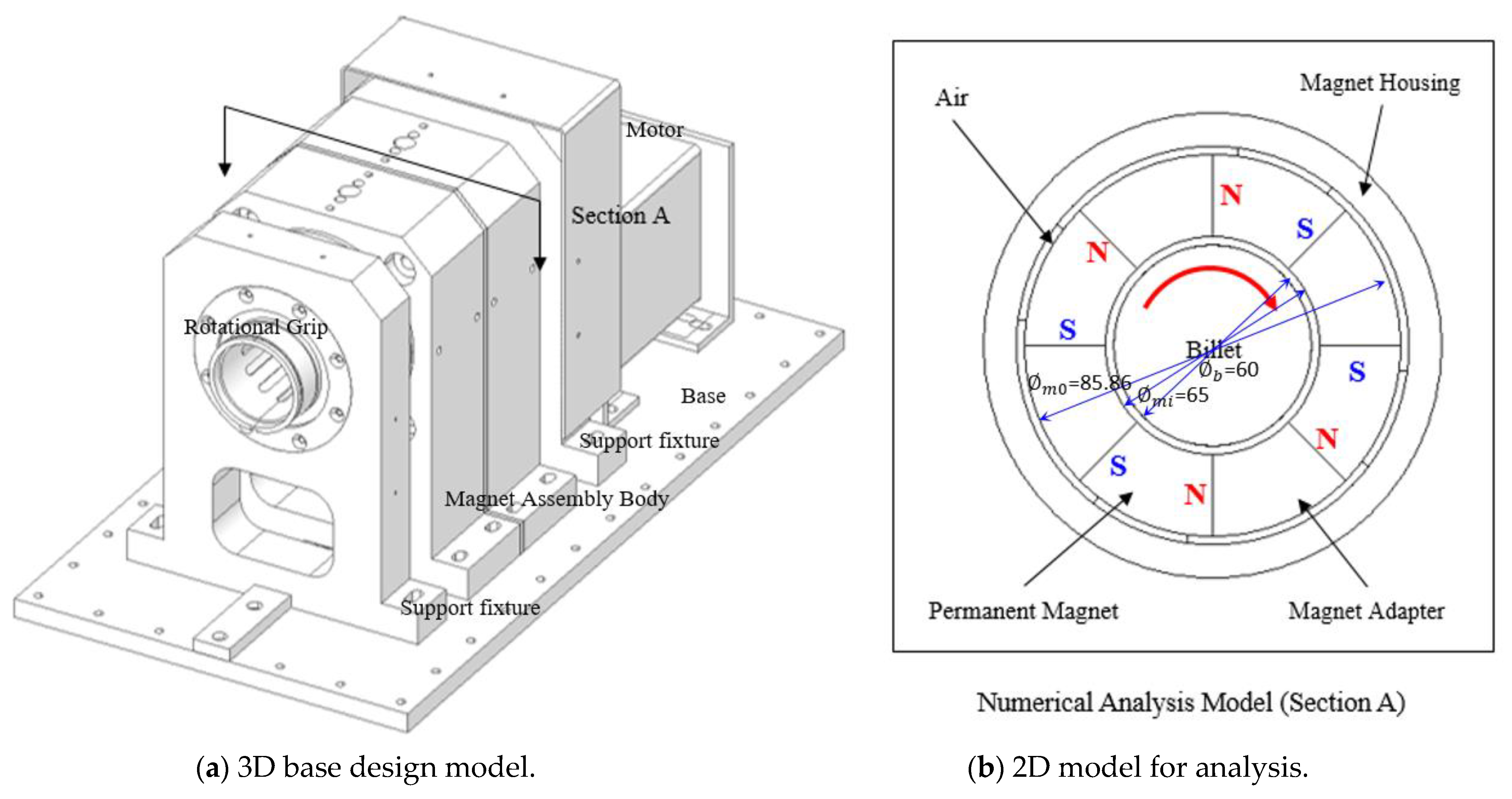
3.1. Base Model of Induction Heating with Permanent Magnet

The basic model considered for analysis in this study is a system that is composed of a ring-type permanent magnet consisting of magnetic poles arranged in the tangential direction and that produces heat by inducing current in the electromagnetic field by rotating the billet. The model can be divided into the rotor of the billet and the stator, in which permanent magnets are arranged. The stator part consists of permanent magnets (NdFeB), a magnetic adapter, and magnet housing, whereas the rotor consists of a billet. The analysis model is composed of four permanent magnets arranged in the tangential direction, facing one another. As a result, the rotary billet heating model has periodicity in the tangential direction. Furthermore, since the arrangement of the heating system is equally extended in the longitudinal direction, the electromagnetic–thermal analysis was performed by simplifying it as a 2D model, as shown in Figure 2b. Considering the operating and assembly tolerance as a geometric design factor of a 60 mm billet heating device, the distance between the billet and the magnet was set, and the size of the magnet to form a sufficient magnetic field was set as shown in Figure 2.

3.2. Properties and Boundary Conditions of Billet Heating

Regarding the physical properties of the analysis model for the billet heating characteristics of the induction heating system, the same physical properties and boundary conditions were applied to the real designed system. The physical properties of each component of the heating system, that is, the billet (aluminum), permanent magnet (NdFeB), magnetic housing, and magnetic adapter, are listed in Table 1. For the permanent magnet (NdFeB), graphs of various shapes of physical properties according to the grade are available, and the analysis was performed using the BH curve of NdFeB N35 shown in Figure 3. The effects of temperature on the exterior parts were considered by applying the electric properties (electrical resistivity, relative permeability) and thermal properties (thermal conductivity, specific heat, and volumetric heat capacity), which vary with temperature.
The model configuration and boundary conditions of the rotary induction heating system are summarized in Table 2. First, the geometric condition was applied for the permanent magnet configuration for system heating. As for the configuration of permanent magnets of a rotary induction heating system that has been actually placed, four magnets were arranged in the tangential direction in a structure such that the magnets face one another. The clearance between the permanent magnet and billet is 2.5 mm, the diameter of the billet is 60 mm, and the length of the billet is 75 mm. The magnet has a size of 65 mm, an internal diameter of 65 mm, an angle of 45°, and a height of 15.43 mm.
For inducting heating, the billet is rotated by the DC motor with a speed of up to 4000 RPM, considering the operation conditions of the motor. The time taken by the rotor to reach the rotational speed of 4000 RPM was set to 30 s. Furthermore, the sink temperature condition was applied using the infinite box function to the air surrounding the heating system. The infinite box assumption was applied to reflect the infinite realm of air, and it was set to indicate the heat transfer because of the temperature difference between the heating system and air.
In this study, an experiment and analysis were performed on the base model, and the reliability of the analysis was secured through the base model by comparing the experiment and analysis results.

3.3. Comparison between Numerical Analysis and Experiment

3.3.1. Analysis of the Base Model

Electromagnetic–thermal analysis was performed for the model of the induction heating system using permanent magnets arranged in the tangential direction, as proposed in the previous section. The finite element model and boundary conditions are shown in Table 2. Furthermore, the magnetic flux density, current density, power loss, and temperature distribution were examined to verify the heating characteristics of the billet, and the results are shown in Figure 4. As shown in Figure 4, the magnetic flux distribution inside the billet is concentrated in the outermost part owing to the high-speed rotation of the billet. This phenomenon can be attributed to the induced electromotive force caused by an electric field and magnetic field. It appears owing to the eddy current, which forms a closed loop in the local area inside the conductor to cancel the internal magnetic field. Consequently, it can be observed that the maximum current and power loss occur at the same position where the magnetic flux density is concentrated due to the current density.
The temperature distribution of the induction heating system indicates that the surface of the billet where the magnetic flux density is concentrated has the highest temperature, and the part where the magnetic flux density is concentrated in the main heating source. Moreover, it was found that the heating performance may vary with the amount of power loss.
Regarding the heating performance of the rotary induction heating system, the energy consumption can be derived using the torque and heating time as follows:
P = N T t m η
where, m, N, T, and t denote the billet weight, rotational speed, torque, and heating time, respectively. Equation (6) shows that the energy consumption is proportional to the rotational speed, torque, and heating time. Therefore, it can be seen that the relationship between the rotation speed and heating time is inversely proportional to the same energy consumption and torque. On the other hand, if the power loss and rotation speed are constant, it can be seen that the torque and heating time are inversely proportional. The energy consumption of the rotary induction heating system was calculated using a power factor of ( η ) = 0.8, which was derived by the ratio of the motor’s active power and apparent power. It was found that the rotary induction heating system had an energy consumption of 302.57 kWh/ton.

3.3.2. Experiment Results Using the Base Model

The rotary induction heating experiment model was fabricated using the same conditions as used in the analysis. The motor was rotated at 4000 RPM. In addition, the temperature of the cylindrical billet surface was measured through the support holes on the billet. The experimental setup is shown in Figure 5.
In the experiment, the temperature over time was measured and the results are shown in Figure 6. It can be observed that the heating efficiency increased with the rotational speed of the billet based on the temperature–time and RPM–time curves. However, the change in the thermal properties of aluminum due to the increase in the billet temperature changed the physical properties of the aluminum and interfered with the heating process. Moreover, the rate of the temperature rise decreased over time as the heat loss to the surrounding environment increased. Consequently, it can be observed that a heating time of approximately 260 s was required until the billet reached 450 °C.

3.3.3. Comparison between Analysis and Experiment Results

The temperature changes over time were compared between the rotary induction heating experiment and analysis results, as shown in Figure 7. As shown in this figure, the temperature–time data of the experiment and analysis had a low increasing slope of temperature in the early stage. The temperature rising slope was low for the time when the rotational speed increased from 0 to 4000 RPM; however, after 4000 RPM, it can be observed that the temperature slope increased to reach an inflection point. As the billet temperature rose, the electrical resistivity, density, and specific heat increased. Accordingly, the heating value of the billet became higher, and the rate of increase in the temperature graph gradually decreased.
The temperature–time curve of the rotary induction heating system generally rose in a similar way. Overall, it can be observed that the trend of the temperature increase over time has a good agreement between the experiment and analysis results. Moreover, the temperature difference at around 260 s, when the aluminum billet reached near 450 °C, was approximately 2%. This suggests that the actual heating value in the experiment became lower than the analysis data due to the mechanical losses of the power transmission parts, that is, the gears, bearings, and motors, and the surrounding thermal loss, which were not considered in the analysis. Consequently, the analysis and experiment results can be said to match well with each other, thus securing the reliability of the analysis procedure. The measurements were made using a jig and grip at the same time. As a result, when measuring within the allowable focal length of the instrument, the difference between the measurement results using the grip and jig was negligible within 0.5%. In addition, the experiment was performed three times, and the temperature deviation showed an average of 3.4 and a standard deviation of 4.2.

4. Heating Characteristic Effects on Design Parameters

In this section, the effects on the design and operation factors, that is, the magnetic flux direction, number of magnets, and the clearance and eccentricity characteristics between the billet and magnet were analyzed based on the base model.

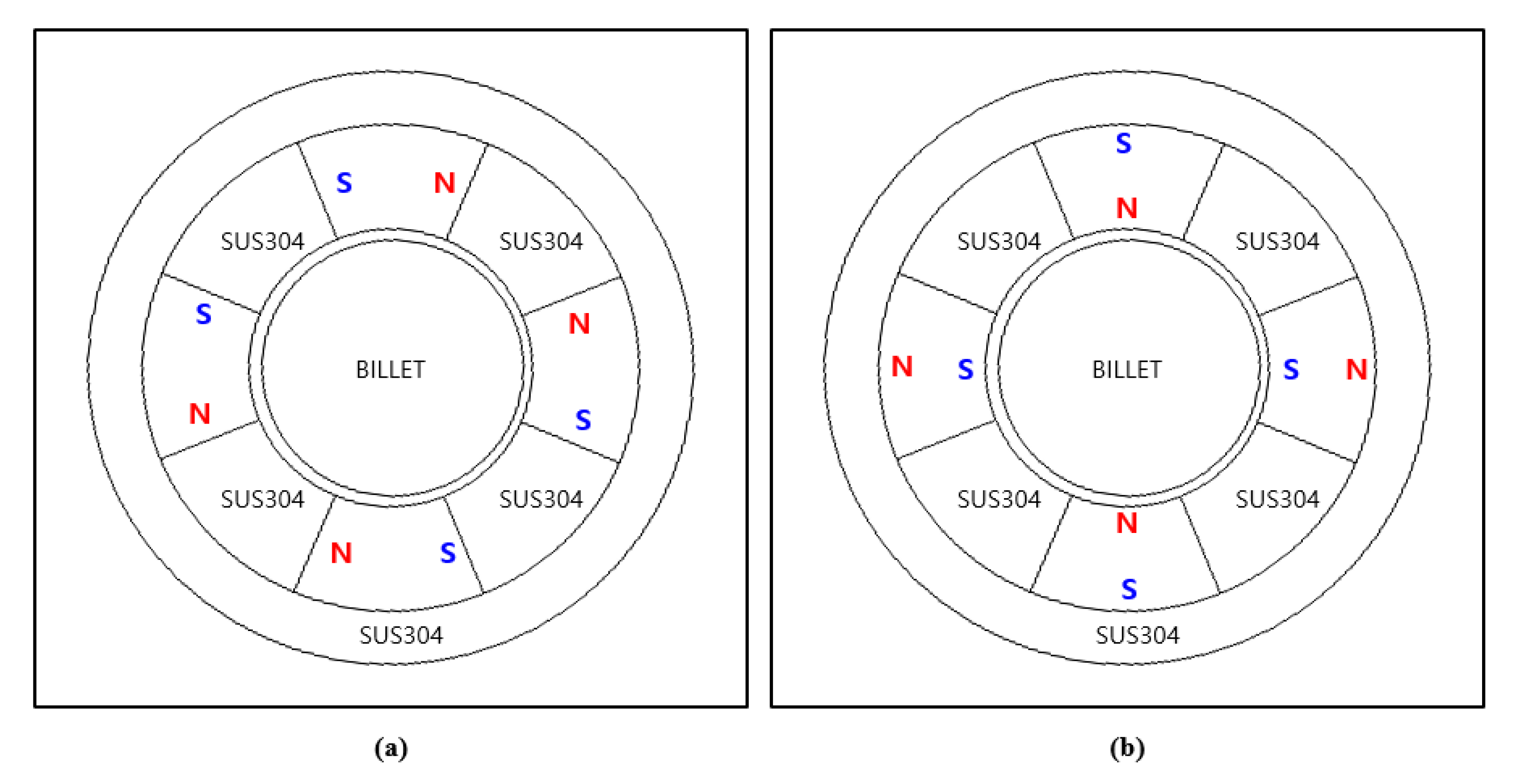
4.1. Heating Effect for Magnetic Polarity Direction

The polarity direction of the magnetic field of the induction heating system using permanent magnets can be arranged in the normal or tangential direction. Therefore, in this study, the effects of the two forms of magnet arrangement were analyzed, as shown in Figure 8, to examine the effects of the changes in the magnetic polarity direction. The tangential model in Figure 8a was configured in such a manner that each pair of permanent magnets with the same pole were placed to face each other, whereas the normal model in Figure 8b was configured in such a manner that the magnet poles would be formed toward the center axis of the circle and the N and S poles would be placed alternately.
The numerical analysis of the billet heater using permanent magnets was performed with the same conditions as the analysis method of the base model, and the results are shown in Figure 9. The results in Figure 9 are listed in the order of magnetic flux density, vector potential, active power density, current density, and temperature. The results of the electromagnetic–thermal analysis according to the polarity direction of the billet heater using permanent magnets confirmed that due to the surface effect, the magnetic flux density is concentrated in the outside of the billet in both models, as shown in Figure 9. It can be observed that in the tangential model, the magnetic flux density on the billet surface is concentrated at four points around the center of the magnet, whereas, in the normal model, it is concentrated in eight areas on the edge of the magnet. This indicates that different magnetic fields are formed according to the polarity direction even when permanent magnets with the same flux density are used, and that although the range of the maximum and minimum magnetic flux density is not wide enough, the area of the concentrated magnetic field is larger in the normal direction. As a result, in the normal model, a high eddy current occurs inside the billet, and the current density and power density values are also higher. Hence, it can be observed that power density is determined by the flux penetration of the billet surface due to the magnetic flux density and surface effect, and the normal model is advantageous for heating over the tangential model among the four permanent magnet models.
The temperature result according to the changes in the permanent magnet flux direction showed that the temperature increased the heating time. As shown in Figure 9, in the case of the tangential model for the flux direction, the heating time and energy consumption at which the temperature of the billet reached 450 °C were approximately 260 s and 302.57 kWh/ton, and in the normal model, they were approximately 70 s and 287.01 kWh/ton, respectively. Thus, the normal model for the flux direction improves the heating time by approximately 73% and the energy consumption by approximately 5% compared to the tangential mode.

4.2. Heating Effect Based on Number of Magnets

In this study, the effects of the increasing number of permanent magnets from 4 to 16 in the tangential and normal models, as mentioned above, were analyzed. All the permanent magnets were arranged with the same clearance, and the same flux direction arrangements of tangential and normal models were applied to the analysis.
The results of electromagnetic–thermal analysis based on the increased number of permanent magnets are shown in Figure 10 and Figure 11. In the normal model, the power loss of the billet gradually decreased as the number of magnets increased. In the normal model, the hourly power loss of the billet gradually decreased as the number of magnets increased. This is because the magnetic force transmitted into the billet decreased despite the increase in the number of magnets and the decrease in the spacing. The biggest difference between the normal and tangential models is the difference in the form of the magnetic flux penetrating into the billet depending on the polarity direction; the normal model shows a deeper penetration into the billet than the tangential model. In contrast, it can be observed that the power loss gradually increased with the number of magnets for the tangential model, and an inflection point was reached when the number of permanent magnets was 12. Furthermore, the same phenomenon appears in the graphs of the time to reach 450 °C and the number of magnets. As described in the four cases above, this is due to the interference between permanent magnets. The narrower the clearance was, the lower the heating efficiency was as the magnetic flux, which should penetrate the billet, flows into the adjacent permanent magnet.
Furthermore, when the temperature distribution with the increasing number of magnets was examined, as shown in Figure 9, the temperature distribution inside the billet of the tangential model showed a temperature difference of approximately 20 °C between the surface and center. In contrast, the normal model showed a temperature difference of approximately 5 °C.
In this section, the effects of the increasing number of permanent magnets were analyzed using electromagnetic–thermal analysis, and the clearance between the permanent magnets was found to be a major parameter that influenced the heating efficiency. As the number of tangential direction magnets increased, flux density and current density increased and then decreased. This was because, as the number of magnets increased, as the poles of the magnets became closer, the amount of flux and current generated by the Al ingot by the interference of flux decreased. In addition, the required torque increased due to the increase in the number of magnets, and the increased torque became a factor to reduce the power loss. In Figure 10, the conversion capacity to heat is high in the 12 magnets, with the maximum power loss and a short heating time. Energy consumption was the most efficient when the power loss was large and the heating time was short. Energy consumption according to the number of magnets is shown in Table 3. As shown in the table, the tangential model with 12 permanent magnets showed the best heating efficiency in consideration of the clearance between the permanent magnets.

4.3. Analysis of Effects of Change in the Clearance between Billet and Permanent Magnet

For the analysis of the model based on the clearance between the billet and the permanent magnet, the tangential model with 12 permanent magnets, which showed the highest heating value, was selected. The design parameters were defined such that the permanent magnets maintained a constant volume by changing their outer radius with the change in the clearance between the billet and permanent magnets. In view of processing and assembly, the minimum clearance was defined as 0.5 mm. To analyze the heating performance according to the changes in the inner and outer radii, the inner radius was set to 30.5–33 mm, as shown in Table 4, and the outer radius was set to 46.60–48.27 mm by Equation (7), as follows:
R i = R o 2 + 2 C θ
where C is the cross-sectional area of the permanent magnet, Ri is the inner radius, Ro is the outer radius, and θ is the arc angle of the permanent magnet.
On this basis, the analysis model with an inner radius of 30.5 mm was defined as Case01, and the heating characteristics were analyzed using six models in total with 0.5 mm increments.
The results of the electromagnetic–thermal analysis with different clearances of the induction heating system are shown in Figure 12 and Table 5. As the clearance of the permanent magnet and billet increased, the magnetic flux density, current density, and power loss decreased. When the power loss was checked in Figure 12, the Case01 model with the smallest clearance with the billet had the maximum heating efficiency. This indicates that it is advantageous to design the clearance between the magnet and billet as small as possible within the allowable range. Moreover, it shows nonlinear characteristics for the clearance.

4.4. Heating Effect for Billet Assemble Eccentricity

In this section, the characteristics of the eccentricity of the billet heater using permanent magnets that can occur as the billet rotates were analyzed. To that end, numerical analysis models were configured by changing the clearance between the billet center and the billet heater center. The eccentric distances were applied at 0.5 mm intervals in the range of 0–2 mm in consideration of the internal air gaps. The billet heating characteristics were analyzed by applying the arrangement of 4 and 12 permanent magnets to the tangential model.
When the rotary induction heating system was driven with eccentricity given to the billet and the heating object, the trend of flux linkage was changed due to a change in the flux density of the air gap. A change in the flux linkage changed the trend of loss by magnetic flux density, current density, and eddy current. The change in the magnetic flux density as a result of the electromagnetic–thermal analysis according to different eccentric distances is shown in Figure 13. As shown in Figure 13, the maximum current density in static eccentricity was 7.36 × 10⁷ A/m2; however, as the eccentric distance was increased by 0.5 mm, the maximum current density was increased to 7.45 × 10⁷, 8.17 × 10⁷, 8.28 × 10⁷, and 8.89 × 10⁷ A/m2, respectively. A higher current density asymmetrically occurred on one surface owing to the change in the clearance between the permanent magnet and billet caused by the eccentricity of the rotation of the billet.
The increase in the current density inside the billet also affected the power loss. To analyze the power loss in the billet, the mean power losses in the billet are shown in Table 6. The power losses in the billet in static eccentricity (eccentricity of 0 mm) where the stator and rotor rotate coaxially were 3.23 and 3.49 kW and those in the dynamic eccentricity (eccentricity of 2.0 mm) were 3.29 and 3.90 kW, respectively. That is, it was confirmed that the power loss increased by about 1.79% in the four permanent magnets to the tangential model, and increased by about 10.51% in the 12 permanent magnets to the tangential model when an eccentricity of 2 mm was applied at a clearance of 2.5 mm.
Since eccentricity can increase the power loss by decreasing the clearance, the heating efficiency was improved. However, as shown in Table 6 and Figure 14, the size of the ripple increased due to the asymmetry of magnetic force, and there was a risk of mechanical vibration and noise.

4.5. Effects of Magnet Arrangement Clearance

As a result of analyzing the characteristics of each design parameter, the maximum for the number of magnets could not be analyzed and it continued to decrease for the centrifugal magnetic field model. Hence, in this section, a model with the circumferential direction of the magnetic field was set, and the optimal conditions were derived by optimizing the distance gap between magnets under the same volume of magnets.
To optimize the billet heater using permanent magnets for the tangential circumferential direction, the outer radius was adjusted to maintain a constant volume of the magnets while maintaining the inner radius constant at different angles of the magnet (θ) as shown in Figure 15. This causes changes in the geometric characteristics that adjust the clearance between magnets while maintaining the equal total flux of magnets. Furthermore, the billet heater was composed of 12 permanent magnets based on the previous analysis result of the effects of the number of magnets. The clearance between the permanent magnet and billet was set to 0.5 mm considering the manufacturing and assembly tolerances, and the inner radius (R0) of the permanent magnet was set to 30.5 mm. Therefore, the combinations for the analysis of the design parameters, including the angle (θ) and outer radius (R1) of the permanent magnets and excluding the fixed design parameters, are listed in Table 7.
The results of the electromagnetic–thermal analysis according to the changes in the angle and outer radii of the billet heater using permanent magnets are shown in Figure 16 and Table 8. As the angle of the permanent magnet increased, the surfaces adjacent to the billet increased and the outer radius of the permanent magnet decreased at the same time. In other words, the clearance between the permanent magnets decreased. When the results of Case01 to Case04 were analyzed, the larger the surface adjacent to the billet was, the higher the magnetic flux density, current density, and power loss, and the higher the heating efficiency inside the billet. Consequently, an increase in the torque and a reduction in the heating time can be predicted.
With the change in the angle of the permanent magnet, the clearance between the permanent magnets gradually became narrower. As shown in the distribution of Case05, if the clearance between the permanent magnets became too small, the amount of magnetic flux density that entered the interior of the billet increased, and the value of the torque due to the electromagnetic force increased. As shown in Figure 16b, the power loss increased rapidly and the heating efficiency of Case05 was lower than those of Case01–Case04.
In this study, the heating effects of changes in the inner/outer radius and the angle of the permanent magnets were analyzed to determine the optimal conditions for the location and arrangement of permanent magnets that maintain a constant volume. As a result of the electromagnetic–thermal analysis according to changes in the design parameters of the normal and tangential directions, the optimal model, consisting of 30.5 mm, 40.93 mm, and 25° for the inner/outer radii and angle, respectively, of permanent magnets, showed the best heating characteristics.

5. Conclusions

The electromagnetic–thermal characteristics of a billet heater using permanent magnets were numerically analyzed in this study. To this end, the correlation between the experiment and analysis results was examined, and the reliability of the analysis method was obtained by verifying the analysis method. The electromagnetic–thermal analysis was performed using the analysis method that was proven to be reliable. The electromagnetic–thermal analysis was performed by selecting design parameters such as the polarity direction, the number of permanent magnets, and eccentric distance. Then, the heating characteristics were examined through the prediction of temperature distribution according to changes in the design parameters and analysis of the results.
The results of the analysis model of the billet heater using permanent magnets until reaching 450 °C were compared with the experiment result to achieve reliability within an error rate of 3%.
The analysis results using this model confirmed that the flux penetration and concentration area inside the billet changed by the polarity direction of the permanent magnet, and the heating efficiency varied significantly according to the change in the polarity direction. In particular, even though the flux model of the normal direction had the same surface adjacent to the billet, the heating value inside the billet decreased as the number of magnets increased. For the flux model of the tangential direction, the heating performance gradually increased with the number of magnets; however, the inflection point was formed in a system of 12 permanent magnets.
The cause of this result was found to be the fact that the magnetic flux formed inside the billet due to the arrangement of magnets had a significant effect on the heating efficiency. In the four-magnet model, the normal model for the flux direction improved the heating time by approximately 73% and the power loss by approximately 5% compared to the tangential mode. Furthermore, the examination of the clearance between the billet and permanent magnet confirmed that a smaller clearance was associated with higher efficiency, and a nonlinear characteristic was verified.
Regarding the effect of eccentricity, the trend of flux linkage was changed by the change in the air gap flux density. Furthermore, the heating value increased as the trend of the loss of current density and eddy current inside the billet changed due to the increase or decrease in the clearance between the billet and permanent magnet, and the heating efficiency increased on average. That is, it was confirmed that the power loss increased by about 1.79% in the four permanent magnets to the tangential model, and increased by about 10.51% in the 12 permanent magnets to the tangential model when an eccentricity of 2 mm was applied at a clearance of 2.5 mm. In contrast, the occurrence of ripples of the rotational torque confirmed the possibility of system vibration of the heater.
Lastly, an increase in the wrapping angle of the billet of the permanent magnet influenced the heating time and efficiency, and it had an inflection point at which the power loss decreased and then increased. This suggests that it is necessary to achieve the optimal arrangement. The results herein can be utilized as the design data of heating systems using permanent magnets and as an efficient design guide. In the future, we intend to perform robust design optimization by analyzing the performance while considering the probability distribution of design factors, as well as performing the experimental verification.

Author Contributions

All participating researchers discussed the idea, agreed to the results, and contributed to the manuscript writing. In particular, D.-J.H. ideas and the formulation, planned, organized, validated the research contents as a whole, contributed to the analysis of the results and improvement of the manuscript, supervision, and project administration; S.-I.S. performed the analysis and tests, visualization, and writing—draft preparation. H.-J.L. further analyzed and considered the characteristics of eccentricity. All authors have read and agreed to the published version of the manuscript.

Funding

This research was funded by the Korea Evaluation Institute of Industrial Technology (KEIT), Ministry of Trade, Industry and Energy by the Korean government (MOTIE) and SAMWOOENG, grant number 20010934.

Institutional Review Board Statement

Not applicable.

Informed Consent Statement

Not applicable.

Conflicts of Interest

The authors declare no conflict of interest.

References

  1. Mallick, P.K. Materials, Design and Manufacturing for Light Weight Vehicles; Woodhead Publication: Sawston, UK, 2010. [Google Scholar]
  2. Elmarakbi, A. Advanced Composite Materials for Automotive Applications: Structural Integrity and Crashworthiness; John Wiley & Sons: Hoboken, NJ, USA, 2013. [Google Scholar]
  3. Marshall, G.J.; Bolingbroke, R.K.; Gray, A. microstructural Control in an Aluminum Core Alloy for Brazing Sheet Applications Metall. Metall. Mater. Trans. A 1993, 24, 1935–1942. [Google Scholar] [CrossRef]
  4. Trivedi, A.; Dwivedi, V.K.; Agarwal, M. Cladding techniques that achieve a solid metallurgical bond with the least amount of base material dilution—An overview. ICMED 2021, 309, 01091. [Google Scholar] [CrossRef]
  5. Khan, H.A.; Asim, K.; Akram, F.; Hameed, A.; Khan, A.; Mansoor, B. Roll Bonding Processes: State-of-the-Art and Future Perspectives. Metals 2021, 11, 1344. [Google Scholar] [CrossRef]
  6. Wang, K.; Khan, H.A.; Li, Z.; Lyu, S.; Li, J. Micro friction stir welding of multilayer aluminum alloy sheets. J. Mater. Process. Technol. 2018, 260, 137–145. [Google Scholar] [CrossRef]
  7. Khan, H.; Li, J.; Shao, C. Analyses of friction stir riveting processes: A review. ASME J. Manuf. Sci. Eng. 2017, 139, 090801. [Google Scholar] [CrossRef] [Green Version]
  8. Wang, K.; Li, Y.; Banu, M.; Li, J.; Guo, W.; Khan, H. Effect of interfacial preheating on welded joints during ultrasonic composite welding. J. Mater. Process. Technol. 2017, 246, 116–122. [Google Scholar] [CrossRef]
  9. Göken, M.; Höppel, H.W. Tailoring Nanostructured, Graded, and Particle-Reinforced Al Laminates by Accumulative Roll Bonding. Adv. Mater. 2011, 23, 2663–2668. [Google Scholar] [CrossRef]
  10. Bay, N.; Clemensen, C.; Juelstorp, O.; Wanheim, T. Bond Strength in Cold Roll Bonding. CIRP Ann. Manuf. Technol. 1985, 34, 221–224. [Google Scholar] [CrossRef]
  11. Frolov, Y.; Haranich, Y.; Bobukh, O.; Remez, O.; Voswinkel, D.; Grydin, O. Deformation of expanded steel mesh inlay inside aluminum matrix during the roll bonding. J. Manuf. Process. 2020, 58, 857–867. [Google Scholar] [CrossRef]
  12. Diop, M.A.; Xiaomeng, C.; Hassan, M.I. Billet heat treatment using flue gas for energy efficiency and batching cycle time reduction. Energy Procedia 2017, 105, 3377–3383. [Google Scholar] [CrossRef]
  13. Magnusson, N.; Bersas, R.; Runde, M. Induction heating of aluminum billets using HTS DC Coils. Inst. Phys. Conf. Ser. 2004, 181, 1104–1109. [Google Scholar]
  14. Fabbri, M.; Morandi, A.; Ribani, P.L. Operational Constraints on the DC induction heating of aluminum billets. COMPEL Int. J. Comput. Math. Electr. Electron. Eng. 2008, 18, 816–819. [Google Scholar]
  15. Magnusson, N.; Runde, M. Efficiency Analysis of a High-temperature Superconducting Induction Heater. IEEE Trans. Appl. Supercond. 2003, 13, 1616–1619. [Google Scholar] [CrossRef]
  16. Choi, J.; Kim, K.; Park, M.; Yu, I.-K.; Kim, S.; Sim, K.; Kim, H.-J. Practical design and operating characteristic analysis of a 10 kW HTS DC induction heating machine. Phys. C Supercond. Its Appl. 2014, 504, 120–126. [Google Scholar] [CrossRef]
  17. Morandi, A.; Fabbri, M.; Ribani, P.L. Design of a superconducting saddle magnet for DC induction heating of aluminum billets. IEEE Trans. Appl. Supercond. 2008, 18, 816–819. [Google Scholar] [CrossRef]
  18. Araneo, R.; Dughiero, F.; Fabbri, M.; Forzan, M.; Geri, A.; Morandi, A. Electromagnetic and thermal analysis of the induction heating of aluminum billets rotating in DC magnetic field. COMPEL-Int. J. Comput. Math. Electr. Electron. Eng. 2008, 27, 467–479. [Google Scholar] [CrossRef]
  19. Wang, Y.; Yang, J.; Li, Z.Y.; Jin, Z.; Hong, Z. Study on a numerical method for calculating the heating process of HTS DC induction heater. IEEE Trans. Appl. Supercond. 2013, 24, 1–5. [Google Scholar] [CrossRef]
  20. Wang, Y.; Gao, H.; Li, Z.; Ping, Y.; Jin, Z.; Hong, Z. Study of the temperature uniformity of aluminium billets heated by superconducting DC induction heaters. COMPEL Int. J. Comput. Math. Electr. Electron. Eng. 2015, 34, 357–370. [Google Scholar] [CrossRef]
  21. Kim, J.G.; Hahn, S.Y.; Choi, J.H.; Semertzidis Yannis, K. A Design study on a Multibillet HTS Induction Heater with REBCO Racetrack Coils. IEEE-Inst. Electr. Electron. Eng. 2019, 8, 1051–8223. [Google Scholar] [CrossRef]
  22. Yan, X.; Dai, S.; Ma, T. Electromagnetic and Thermal Analysis of Cylindrical Aluminum Billet Heated by 1MW HTS DC Induction Heater. IEEE Access 2020, 8, 144112–144121. [Google Scholar] [CrossRef]
  23. Bojarevics, A.; Beinerts, T. Experiments on liquid metal flow induced by rotating magnetic dipole. Magnetohydrodynamics 2010, 46, 333–338. [Google Scholar] [CrossRef]
  24. Bullo, M.; Bertazzo, M.; Dughiero, F.; Forzan, M.; Zerbetto, M. Experimental results of a 55 kw permananet magnet heater prototype. Proc. HES-13 2013, 2013, 377–384. [Google Scholar]
  25. Ye, L.; Liang, C.; Liu, Y.; Li, D.; Liu, Z. Performance analysis and test of a novel eddy-current braking & heating system for electric bus. Energy Convers. Manag. 2019, 183, 440–449. [Google Scholar]
  26. Chai, Y.-Y.; Yoon, K.Y. Development of Heater Driven by Motor by using eddy current. J. KIECS 2019, 14, 935–942. [Google Scholar]
  27. Mach, F.; Karban, P.; Dolezel, I. Induction heating of cylindrical nonmagnetic ingots by rotation in static magnetic field generated by permanenet magnets. J. Comput. Appl. Math. 2012, 236, 4732–4744. [Google Scholar] [CrossRef] [Green Version]
  28. Du, H.; Li, J.; Qu, Y. Mathematical Modeling of Eddy-Current Loss for a New Induction Heating Device. Math. Probl. Eng. 2014. [Google Scholar] [CrossRef] [Green Version]
  29. Bensaidane, H.; Lubin, T.; Mezani, S.; Ouazir, Y.; Rezzoug, A. A New Topology for Induction Heating System with PM Excitation: Electromagnetic Model and Experimental Validations. IEEE Trans. Magn. Inst. Electr. Electron. Eng. 2015, 12, 1–11. [Google Scholar] [CrossRef] [Green Version]
  30. Aliferov, A.I.; Vlasov, D.S.; Promzelev, V.A.; Morev, A.E. Induction heating based on permanent magnets with magnetic field concentrators. Int. Conf. Actual Issues Mech. Eng. 2017, 133, 495–499. [Google Scholar]
  31. Zerbetto, M.; Forzan, M.; Dughiero, F. Permanent Magnet Heater for a precise control of temperature in aluminum billets before extrusion. Mater. Today Proc. 2015, 2, 4812–4819. [Google Scholar] [CrossRef]
  32. Piscini, L.; Matt, D.; Gimeno, A. Comparison of different Surface Mounted Permanent Magnet patterns. IEEE Stud. Conf. Electr. Mach. Syst. 2018. [Google Scholar] [CrossRef]
  33. N’Gotta, P. Development of permanent magnet quadrupole for particles accelerator. Phys. Des. Accel. 2015, 2015, 52. [Google Scholar]
  34. Zhu, Z.Q.; Member, S.; Xia, Z.P.; Howe, D. Comparison of Halbach Magnetized Brushless Machines Based on Discrete Magnet Segments or a Single Ring Magnet. IEEE Trans. Magn. 2002, 38, 2997–2999. [Google Scholar] [CrossRef] [Green Version]
  35. Kim, Y.K.; Hong, S.I. Effect of Intermetallic Compound Layer on Peel Strength and Crack Propagation Behavior in Cu/Al/Cu Clad Composites. Metals 2019, 9, 1155. [Google Scholar] [CrossRef] [Green Version]
  36. Kim, I.-K.; Hong, S.I. Mechanochemical joining in cold roll-cladding of tri-layered Cu/Al/Cu composite and the interface cracking behavior. Mater. Des. 2014, 57, 625–631. [Google Scholar] [CrossRef]
  37. Summers, P.; Chen, Y.; Rippe, C.; Allen, B.; Mouritz, A.; Case, S.; Lattimer, B. Overview of aluminum alloy mechanical properties during and after fires. Fire Sci. Rev. 2015, 4, 3. [Google Scholar] [CrossRef] [Green Version]
  38. Lubin, T.; Netter, D.; Leveque, J.; Rezzoug, A. Induction Heating of Aluminum Billet Subjected to a Strong Rotating Magnetic Field produced by Superconducting Windings. IEEE Trans. Magn. Inst. Electr. Electron. Eng. 2009, 45, 2118–2127. [Google Scholar] [CrossRef] [Green Version]
  39. Rudnev, V.; Loveless, D.; Cook, R.L. Theoretical Background from: Handbook of Induction Heating; CRC Press: Boca Raton, FL, USA, 2017. [Google Scholar]
  40. Kumar, R.; La Rocca, A.; Vakil, G.; Gerada, D.; Gerada, C.; Fernandes, B.G. Significance of Anisotropic Thermal Expansion in High Speed Electric Machines Employing NdFeB Permanent Magnets. Energies 2021, 14, 7558. [Google Scholar] [CrossRef]
  41. Deng, D.; Murakawa, H. Numerical Simulation of Temperature Field and Residual Stress in Multi-pass Welds in Stainless Steel Pipe and Comparison with Experimental Measurements. Comput. Mater. Sci. 2006, 37, 269–277. [Google Scholar] [CrossRef]
Figure 1. Numerical analysis procedure of induction heating.
Applsci 12 03052 g001
Figure 2. Geometric diagram of permanent magnet-based billet induction heating.
Applsci 12 03052 g002
Figure 3. Demagnetization curves as a function of temperature for NdFeB N35.
Applsci 12 03052 g003
Figure 4. Analysis result of base model: (a) Analysis result of prototype heating system (b) RPM–time graph; and (c) temperature–time graph.
Applsci 12 03052 g004
Figure 5. Experimental setup of the rotary induction heating system; (a) test scheme; (b) test bed; (c) permanent magnet arrangement; (d) temperature measurement.
Applsci 12 03052 g005
Figure 6. RPM and temperature graph of the base model: (a) RPM–time graph; (b) temperature–time graph.
Applsci 12 03052 g006
Figure 7. Comparison of analysis and experiment results: (a) RPM–time curve; and (b) temperature–time graph.
Applsci 12 03052 g007
Figure 8. Permanent magnet polarity direction change model: (a) tangential direction model; (b) normal direction model.
Applsci 12 03052 g008
Figure 9. Analysis result according to permanent magnet flux direction change: (a) tangential direction result; (b) normal direction result; (c) temperature result.
Applsci 12 03052 g009aApplsci 12 03052 g009b
Figure 10. Result graph showing temperature rise to 450 °C according to the change in the number of permanent magnets: (a) number of magnets–heating value graph; and (b) number of magnets–heating time graph.
Applsci 12 03052 g010
Figure 11. Analysis result according to the number of permanent magnets: (a) result of normal model; (b) result of tangential model.
Applsci 12 03052 g011aApplsci 12 03052 g011b
Figure 12. Analysis result with different clearances—torque, heating time, and energy consumption graphs for case model.
Applsci 12 03052 g012
Figure 13. Changes in current density according to eccentricity.
Applsci 12 03052 g013
Figure 14. Changes in torque ripple according to eccentricity.
Applsci 12 03052 g014
Figure 15. Design parameters for analyzing the effects of magnet arrangement clearance.
Applsci 12 03052 g015
Figure 16. Analysis results according to magnet arrangement clearance: (a) electromagnetic field analysis result; (b) torque, heating time, and energy consumption result graph.
Applsci 12 03052 g016aApplsci 12 03052 g016b
Table 1. Physical properties of billet heating design parts [40,41].
Description20 °C100 °C300 °C500 °C
AlElectrical Resistivity [Ω·m]2.65 × 10−83.56 × 10−86.61 × 10−81.23 × 10−7
Volumetric Heat Capacity [J/m3·K]2.40 × 1062.50 × 1062.65 × 1062.90 × 106
Density [kg/m3]2700268126402590
Thermal Conductivity [W/m·K]236228220210
SUS
304
Electrical Resistivity [Ω·m]7.20 × 10−77.69 × 10−79.00 × 10−71.05 × 10−6
Volumetric Heat Capacity [J/m3·K]3.68 × 1063.90 × 1064.09 × 1064.29 × 106
Density [kg/m3]7960788077907710
Thermal Conductivity [W/m·K]13.415.3517.321.3
NdFeBFlux Density [T]1.21.1--
Electrical Resistivity [Ω·m]1.5 × 10−61.52 × 10−6--
Volumetric Heat Capacity [J/m3·K]3.42 × 106---
Density [kg/m3]7600---
Thermal Conductivity [W/m·K]6.61---
Table 2. Boundary conditions for numerical analysis model.
ConditionValueUnit
Geometric
Condition
Pole4EA
Magnetic DirectionTangential-
Clearance2.5mm
Boundary
Condition
Rotational speed4000RPM
Sink Temperature293K
Uniform Heat SourcevariableW/m3
Table 3. Energy consumption according to the number of magnets.
Number of Magnets48101214
Energy consumption
(Tangential, kWh/ton)
370.91311.46296.78286.75326.27
Energy consumption
(Normal, kWh/ton)
325.68278.83283.20299.17335.01
Table 4. Configuration clearance and radius dimension for construction model.
Case01Case02Case03Case04Case05Case06
Outer Radius
[mm]
46.6046.9347.2647.6047.9348.27
Inner Radius
[mm]
30.5031.0031.5032.0032.5033.00
Clearance
[mm]
0.501.001.502.002.503.00
Table 5. Analysis results with different clearances.
Magnetic Flux
Density [T]
Current Density
[×106, A/m2]
Power Loss Density
[W/m3]
Case01Min796 × 10−9−266455 × 10−9
Max1.398266188 × 107
Case02Min194 × 10−8−211997 × 10−11
Max1.350211119 × 107
Case03Min605 × 10−9−176825 × 10−9
Max1.258176826 × 106
Case04Min200 × 10−8−152131 × 10−9
Max1.248152614 × 106
Case05Min671 × 10−9−134200 × 10−8
Max1.243134479 × 106
Case06Min574 × 10−9120200 × 10−9
Max1.238−120385 × 106
Table 6. Mean heating value and torque ripple in the billet. (NM = Number of magnets).
Eccentricity
[mm]
00.51.01.52.0
Power Loss
[kW]
NM = 43.233.243.253.273.29
NM = 123.493.503.573.703.90
Torque Ripple
[mN·m]
NM = 40.010.020.060.150.37
NM = 120.080.130.210.700.91
Table 7. Model composition for verification of magnet arrangement clearance.
Inner Radius
[mm]
Outer Radius
[mm]
Theta
[Degree]
Clearance
Angle
[Degree]
Case0130.552.841020
Case0230.546.601515
Case0330.543.142010
Case0430.540.93255
Case0530.539.94282
Table 8. Analysis results of normal direction model.
Magnetic Flux Density
[T]
Current Density
[×106, A/m2]
Power loss Density
[W/m3]
Case01Min136 × 10−8−265828 × 10−9
Max1.456265186 × 107
Case02Min734 × 10−9−266394 × 10−9
Max1.439266188 × 107
Case03Min178 × 10−8−273564 × 10−10
Max1.862273193 × 107
Case04Min184 × 10−8−288313 × 10−8
Max2.378288220 × 107
Case05Min641 × 10−9−354633 × 10−8
Max2.961354333 × 107
Publisher’s Note: MDPI stays neutral with regard to jurisdictional claims in published maps and institutional affiliations.

