Article

Numerical Simulation of Time-Optimal Path Planning for Autonomous Underwater Vehicles Using a Markov Decision Process Method

1
Southern Marine Science and Engineering Guangdong Laboratory, Guangzhou 511458, China
2
Shenzhen Key Laboratory of Marine IntelliSense and Computation, Shenzhen International Graduate School, Tsinghua University, Shenzhen 518000, China
*
Author to whom correspondence should be addressed.
Appl. Sci. 2022, 12(6), 3064; https://doi.org/10.3390/app12063064
Submission received: 10 February 2022 / Revised: 9 March 2022 / Accepted: 10 March 2022 / Published: 17 March 2022
(This article belongs to the Special Issue New Trends in the Control of Robots and Mechatronic Systems)

Abstract

:
Many path planning algorithms developed for land or air based autonomous vehicles no longer apply under the water. A time-optimal path planning method for autonomous underwater vehicles (AUVs), based on a Markov decision process (MDP) algorithm, is proposed for the marine environment. Its performance is examined for different oceanic conditions, including complex coastal bathymetry and time-varying ocean currents, revealing advantages compared to the A* algorithm, a traditional path planning method. The ocean current is predicted using a regional ocean model and then provided to the MDP algorithm as a priori. A computation-efficient and feature-resolved spatial resolution are determined through a series of sensitivity experiments. The simulations demonstrate the importance to incorporate ocean currents in the path planning of AUVs in the real ocean. The MDP algorithm remains robust even if the ocean current is complex.

1. Introduction

Autonomous underwater vehicles (AUVs) are deployed in the ocean to carry out specific missions, such as ocean observations, target identification, etc., due to their excellent advantages in maneuverability. In order to complete the mission, the AUV is often required to move to a target location under some constraints, such as the shortest time, shortest distance, and least energy consumption. Avoiding risks or obstacles in the ocean is also required. Aiming at different constraints, relevant path planning algorithms are developed. In this paper, the time-optimal is prioritized.
The path planning algorithms for mobile robots can be divided into two categories: discrete-grid-based and sampling-based planning algorithms [1]. The former one is established on a gridded map. For example, the A* algorithm is transformed from the Dijkstra algorithm by adding a heuristic cost to enhance the computational efficiency. The A* algorithm can be modified, aiming at speeding the convergence of the A* algorithm, such as with iterative deepening A*, lifelong planning A*, and bidirectional A* algorithms [2,3]. Liu et al. [4] introduced an improved A* algorithm for generating the procedure of the normal path and berthing path when considering obstacles with currents and marine traffic. The sampling-based planning algorithm does not directly calculate global optimization on a gridded map. It uses the random scattering of particles on the map to extract map-assisted planning. The probabilistic roadmap [5] and rapidly-exploring random tree algorithms [6] are two typical examples. Recently, some clustering algorithms are also applied to path planning, for instance, the ant colony algorithm, genetic algorithm, etc. [7]. The level-set method is also an important branch of robotic path planning [8].
With the rapid development of artificial intelligence, reinforcement learning is applied to robotic path planning. Julien et al. [9] presented an MDP-based planning method for a robot with wheels. In order to resolve the impact of their surrounding environment, Lou et al. [10] modeled the robotic motion as a Markov process and proposed a probabilistic-model-checking method to seek the optimal path. Singh [11] applied the object-oriented Markov decision process for indoor robots, which greatly simplifies the problem of the so-called “curse of dimensionality”. It reduces the state spaces by making the MDP properties as objects. Pereira et al. [12] used a minimum expected risk planner and a risk-aware Markov decision process to improve the reliability and safety of AUV operation in coastal regions.
Different from the land or air based robots, the AUVs have their special characters due to the underwater environment.
(1)
Low positioning accuracy and high positioning cost
Land robots can directly acquire real-time positions through the global positioning system (GPS) with relatively high positioning accuracy (about 0.5 m [13]). Because of the absorption of electromagnetic waves by seawater, satellite signals cannot be directly received underwater by AUVs. Alternatively, the inertial navigation system (INS) is commonly used for underwater positioning. However, it is expensive while providing low positioning accuracy, which produces about 100 m errors after traveling by 1 km [14]. Its positioning error accumulates over time, which must be frequently calibrated for long-term underwater deployment.
(2)
Low cruising speed and high fault tolerance
Compared with land or air based robots, the maximum speed of underwater robots is much slower, which ranges from about 3 to 10 knots [15]. Except in the harbors, marine traffic is limited. The marine morphology, such as the coastline, islands, and seamounts, is relatively fixed. Therefore, more tolerance is allowed for AUVs to tip or roll over in the ocean.
(3)
High impacts by the marine environment
In the ocean, the current velocity, and the speed of AUVs are usually in the same order of magnitude. If the ocean current is neglected, it will lead to an obvious deviation between the planned and practical paths. In contrast, if a real-time robust control is applied to eliminate these deviations, it will cost extra power and computational resources.
Several works have been done to solve the AUV path planning problem. Garau et al. [16] used the A* searching procedure to determine the optimal path with consideration to the ocean currents and their spatial variabilities. Zeng et al. [17] introduced a quantum-behaved particle swarm optimization algorithm for solving the optimal path planning problem of an AUV operating in environments with ocean static currents. Witt et al. [18] described a novel optimum path planning strategy for long-duration operations in environments with time-varying ocean currents. Kularatne et al. [19] presented a graph-search-based method to compute energy-optimal paths for AUVs in two-dimensional (2-D) time-varying flows. Subramani et al. [20] integrated data-driven ocean modeling with the stochastic dynamically orthogonal level-set optimization methodology to compute and study energy-optimal paths. Lolla et al. [21] predicted the time-optimal paths of autonomous vehicles navigating in any continuous, strong, and dynamic ocean currents through solving an accurate partial differential equation. Rhoads et al. [22] presented a numerical method for minimum time heading control for the underwater vehicle moving at a fixed speed in known time-varying and two-dimensional flow fields.
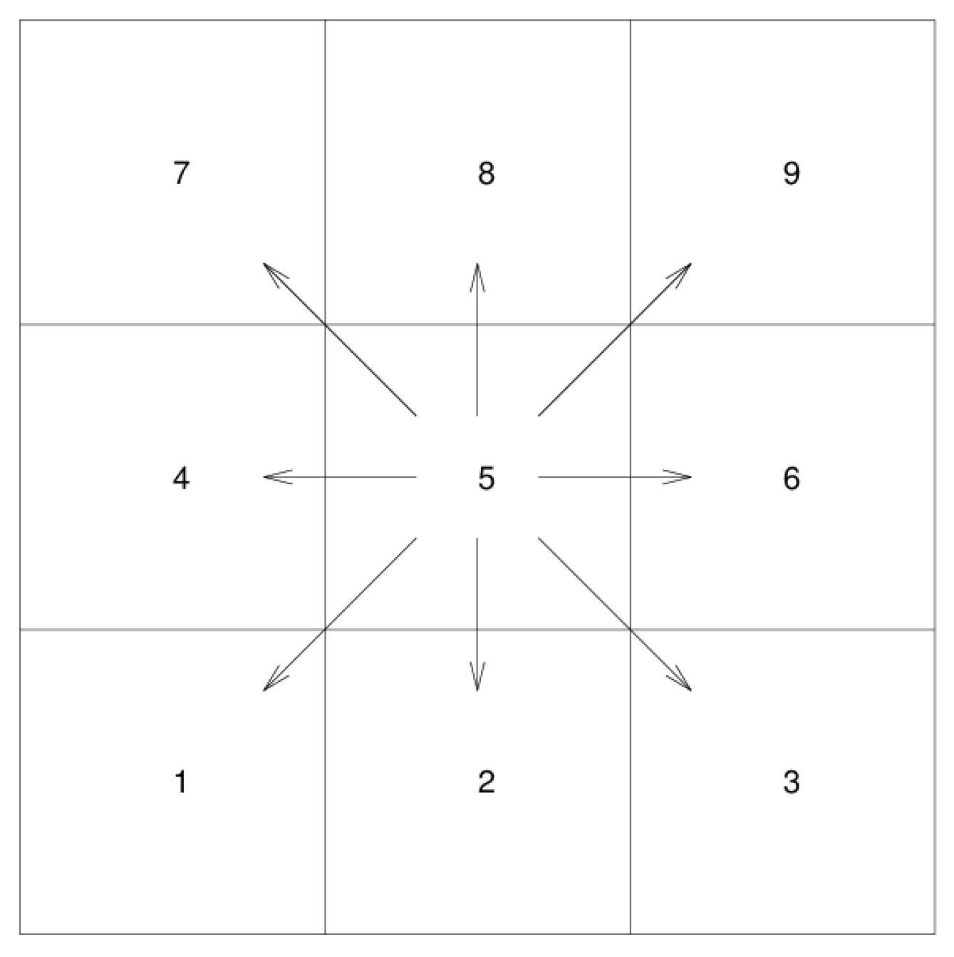
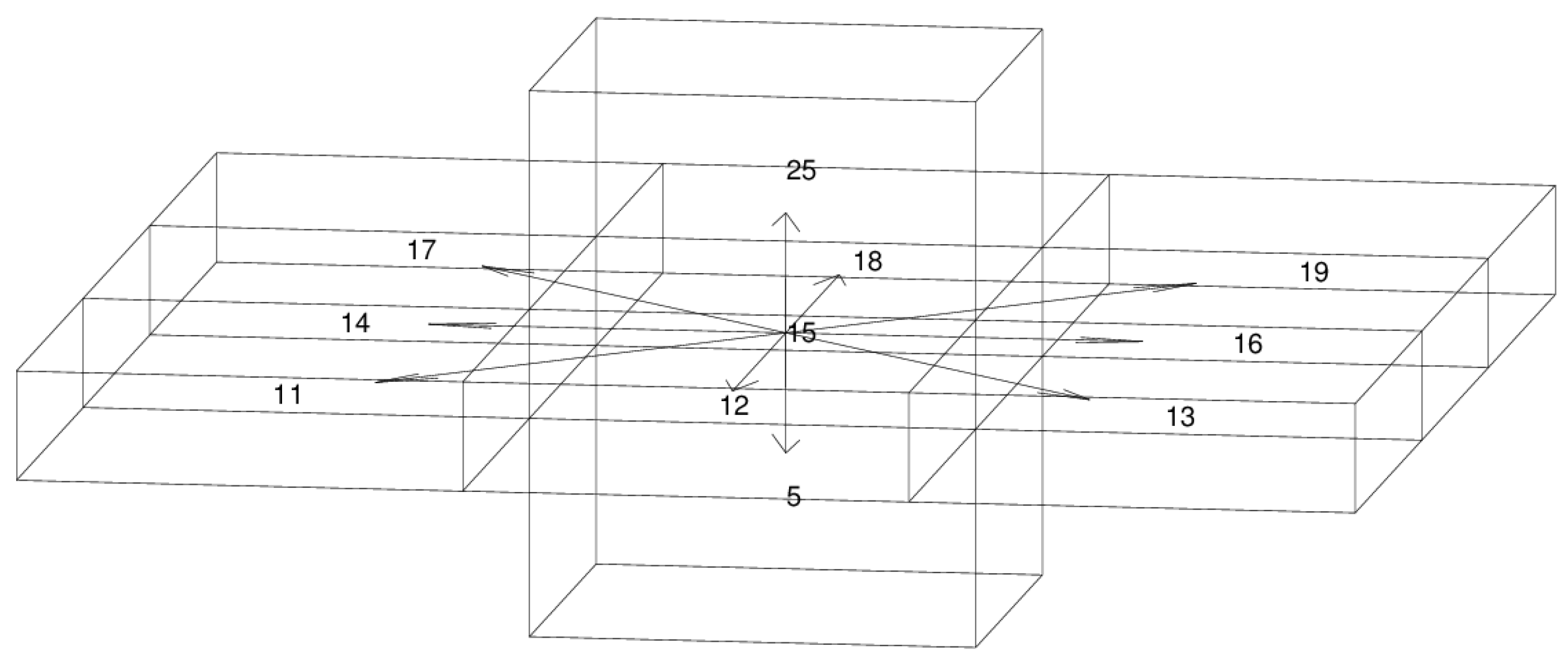
The MDP method is suitable for the AUV underwater path planning. The MDP seeks a globally optimal solution through a value iterative method. The optimal paths of all state points in the whole domain to the target are computed only once. This is more efficient than the traditional A* algorithm [23,24], which has to repeat similar computations for every step. Because AUVs move underwater with a low cruising speed and a high fault tolerance, the actions of AUVs are limited, and thus, suitable for establishing the MDP model. Otherwise, computational difficulties will increase exponentially with increasing robotic actions. In our application, the ocean current is predicted from an oceanic forecast model, therefore the ocean currents can be regarded as fully observable. This information is provided to the AUV as a priori or in real-time through acoustic communications so that the parameters used in the MDP model can be updated. The fully observable MDP model has a faster convergence rate than the partially observable MDP models.
The paper is organized as follows. The principle of the MDP path planning and its numerical algorithm for applications in the AUV navigation are introduced in Section 2. In Section 3, the efficiency of the MDP algorithm is examined and its performance is compared with the traditional A* algorithm. Then, the ocean currents predicted by a regional ocean model are incorporated into the MDP model to evaluate the performance of the MDP algorithm in a ‘real’ oceanic environment. The conclusions are presented in Section 4.

2. Path Planning Algorithm Based on the Markov Decision Process (MDP)

2.1. Markov Decision Process

The target region is first divided into multiple orthogonal grids. For path planning, an action that the AUV takes only depends upon the present state, not on the previous ones that it has experienced. Here, the state specifically refers to the appearance of the AUV inside a grid, rather than the movement process of the AUV itself. Since each grid usually ranges from several hundreds of meters to several kilometers, which is much larger than the actual size of the AUV (usually 1 to 10 m), the AUV has enough time and space to adjust its state inside the grid. Therefore, the AUV’s movement can be treated as a Markov process. A tuple including five parameters (S, A, {   P s , s a } , γ, R) is used to describe this process. Here, S is a state set, providing information of the position and velocity of the AUV. A denotes an action set, which the AUV takes to move from its present grid to neighbors. {   P s , s a } denotes a transition probability matrix, defined as:
P s , s a = P [ S t + 1 = s | A t = a , S t = s ] ,
in which P s , s a is the probability when the AUV changes from its current state s to its successor state s′ by taking an action a. Thus:
s P s , s a = 1   and   P s , s a ,
γ [ 0 , 1 ] is a discount factor, which is used to adjust the proportion between the present and future values. In our simulation, we choose the discount factor γ = 0.95. R is a reward function which is a function of S and A, i.e., R : S × A R . R S a denotes the reward for the AUV to take an action a in the present state s. Its value is predicted by A and S at step t, i.e.,
R S a = E [ R t + 1 | A t = a , S t = s ] ,
in which Rt+1 is the reward that the AUV gets at the next step t + 1. Thus, the Markov decision process is described as:
s 0 a 0 s 1 a 1 s 2 a 2 s 3 a 3 s 4 a 4
The goal is to find an optimal strategy from all possible actions to maximize the expectation of the system’s total reward, i.e., max E [ R ( s 0 ) + γ R ( s 1 ) + γ 2 R ( s 2 ) + ] . The Bellman equation [25] is used to iteratively solve the Markov decision process. When the AUV takes an action in the present state s following a strategy π, the expectation of total reward functions become:
V ( s ) = E [ R ( s 0 ) + γ R ( s 1 ) + γ 2 R ( s 2 ) + | s 0 = s , π ] = E [ R ( s 0 ) + γ ( R ( s 1 ) + γ R ( s 2 ) + ) | s 0 = s , π ] = E [ R ( s 0 ) + γ V π ( s 1 ) | s 0 = s , π ] ,
in which R(s) indicates the reward in the current state s.

2.2. Value Iteration Method

The general solution of the MDP algorithm can be obtained through the value iteration or strategy iteration [26]. The value iteration method can give the optimal strategy from an arbitrary point to the target, which is suitable for the real-time control of AUVs. Its abbreviated process is described below.
In Algorithm 1, we use the greedy strategy to compute Vn(s′), i.e., assuring the maximum reward in every iteration. And then the Bellman Equation (5) is used to solve V(s). π(s) is solved using the value iteration method. It turns out that the solution is convergent to the optimal strategy π*(s) [27].
Algorithm 1. The Value Iteration in the MDP Algorithm
INPUT: MDP five-tuple (S, A, {   P s , s a } , γ, R), max iteration number N, deviation ε
ITERATION:
s S , V 0 ( s ) = 0
for n in range (1, N):
for each state s do:
V n + 1 ( s ) = max a A s P ( s | s , a ) ( R ( s , a ) + γ V n ( s ) )
if s   | V n + 1 ( s )   V n ( s )   | < ε :
break
for each state s do:
π ( s ) = arg max a A s P ( s | s , a ) ( R ( s , a ) + γ V n ( s ) )
  OUTPUT: π(s)

2.3. Determination of Markov Action Sets

In order to provide the state sets for path planning, the area for AUV deployment is mapped to discretized grids according to the bathymetry and coastline. Islands or obstacles, where the AUV cannot pass through, are marked on the gridded map. In the 2D case, the AUV moves only on a horizontal level. The grids, where the AUV can arrive at the successor step, are labeled by numbers 1 to 9 (Figure 1). Initially, the AUV is in the center grid 5. After the AUV takes an action i (i = 1, 2…9), the AUV can only appear in its adjacent eight grids. Otherwise, it stays in grid 5 by taking no action. In the 3D case, the AUV can reach 27 cubes (Figure 2). Technically, it can only move to its adjacent 26 cubes by taking effective action, otherwise, staying in cube 15 by taking no action. Since the aspect ratio of the ocean—which is a ratio between the depth and horizontal length scale—is usually much less than 1, only vertically upward and downward movements are kept for the vertical actions, thus the action set can be significantly reduced through dumping the other 16 actions related to vertical movements. Now, the size of the state set s is reduced from 27 to 11. This division of actions is suitable for the practical movement of AUVs. Table 1 shows the partitioning of the 3D action set.

2.4. Markov Reward Function

Except for the terrains, as usually considered for land-based robots, the ocean current is an important factor for underwater navigation because its magnitude is in the same order as the cruising speed of the AUV. In this paper, we assume that the AUV moves at a constant cruising speed v1 = 0.5 m/s (1 knot). If the ocean current is v2, the absolute velocity of AUV is the vector sum of v1 + v2. The actual trajectory is along the direction of action a. If na is used to represent the unit vector along the direction of action a, the absolute speed of AUV is (v1 + v2)·na. In the 2D case, the distance L for the AUV to travel from the present to successor grid is:
L = { 0.5 d   if   a = action   5 d   if   a = action   2 , 4 , 6 , 8 . 1.4 d   if   a = action   1 , 3 , 7 , 9
Here, d is the grid size. In the 3D case:
L = { 0.5 d   if   a = action   5 d   if   a = action   2 , 4 , 6 , 8 1.4 d   if   a = action   1 , 3 , 7 , 9 0.02 d   if   a = action   10 , 11 .
Thus, it takes L/(v1 + v2)·na for the AUV to move from one grid to its adjacent grid through taking the action a. The goal of the MDP algorithm is to find the optimal path to maximize the total reward expectation. Here, we focus on time-optimal path planning, so we set the reward function as a function of travel time. The principle of the reward function is that the shorter the travel time between grids, the larger the corresponding reward function. A parameter RS is then defined. To make sure that the reward function decreases with each step, RS is −1 in each grid except for when the grid is the target or includes an obstacle. In order to obtain the maximum reward in the target grid, RS is set to be a large positive number, whose magnitude is in the same order as the total grid number, for instance, Rs = +1000 in our case. In this way, the algorithm can make the AUV reach the target as soon as possible and also avoid detours around the target. While in the obstacle grid, RS= −1000 to prevent the AUV from reaching this grid. The reward function is designed as:
R S a c = [ w L ( v 1 + v 2 ) n a ] R S ,
which represents the reward for the AUV to take an action a in the present state s. Here, w is the weight coefficient. The superscript ac represents considering the influence of ocean currents. R s a will be used to represent the reward function without ocean currents. The reward function (10) is always greater for the AUV moving along the current than against it, so the AUV prefers to move along the current to achieve an optimal path. However, it is not necessary to require the optimal path to be along the ocean current because the MDP only requires the total reward function (3) to reach its maximum. Since the vertical current is usually too weak to affect the AUV’s speed, the reward function R s a c is the same for both 2D and 3D cases.
The cruising velocity v1 of the AUV is assumed to be constant. If the ocean current is ignored, v1·na is set to be 1 to simplify the calculation. In this case, the shortest path is equivalent to the shortest arrival time.

2.5. Transition Probability

The ocean currents predicted by a regional ocean model are used in the simulation, but uncertainties between the prediction and the real ocean currents always exist. The transition probability P(s|s, a), which denotes the probability of reaching the state s′ from s by taking an action a, is introduced into the MDP model to describe the uncertainties. When the AUV takes an action a, a random number v′ is added to the local ocean current v2 to decide which grid the AUV can reach next. This process is repeated and the total number to arrive at the adjacent grids is counted. Then, this number is divided by the total number of repetitions to obtain the transition probability P(s|s, a). By applying the above simulation to all the grids, the transition probability matrix can be obtained.

3. Numerical Simulations

3.1. Experimental Region

The Daya Bay, a semi-closed bay on the northern coast of the South China Sea, is selected as the experimental field for numerical simulations. Autonomous platforms equipped with environmental sensors are planned to be deployed for environmental monitoring as a complement to traditional means, such as research vessels, buoys, etc. The coastline of Daya Bay is retrieved from the Global Self-consistent, Hierarchical, High-resolution Geography database (GSHHG) and the bathymetry from a digitalized nautical chart (Figure 3). The geographic coordinates are first transformed to the Cartesian coordinates. Different from land-based robots, obstacles encountered by AUVs in the ocean are offshore islands, bottom topography, and ships. The ships can be avoided using real-time marine traffic information, such as barrier sonars or ship tracking systems. The AUV maintains a certain distance from the seafloor using single-beam sounders. Since the AUVs are usually deployed in the open ocean, only coastline and islands are considered as obstacles in our simulation. Obstacles due to bottom topography and ships are ignored. The travel time for the AUV arriving at the target from its initial location is used to evaluate the performance of the MDP method.
Tidal currents are predicted using the Finite Volume Community Ocean Model (FVCOM) developed at the University of Massachusetts [28], which is a regional ocean model solved using the finite volume technique in unstructured grids. The model is driven by the tidal flows on the open boundaries which are provided by the TPXO global prediction [29], including eight primary tidal constituents (M2, S2, N2, K2, K1, O1, P1, Q1). The model performance has been validated through comparison with the tide gauges in Daya Bay. The AUV initially starts at 17:00:00 6 October 2013 (UTC) corresponding to an ebb tidal course, shown in Figure 4. The tidal current flows offshore and reveals a spatial variation related to water depth. The predicted tidal currents are provided to the MDP method so that the environment is fully observable.
Three typical experiments are designed to examine the performance of the MDP path planning algorithm. Coordinates of the starting and target points in each experiment are given in Table 2. The starting and target points in Case 1 are in a north-south direction without any obstacles along their direct connection. In Case 2, there are islands between the direct connection between the starting and target points. In Case 3, the direct connection between the starting and target points crosses the coastline.

3.2. Sensitivity to Spatial Resolution

The algorithm’s sensitivity to spatial resolution is first examined. It is evaluated by comparing the CPU running time of the algorithm and the optimal path for different spatial resolutions. The running time determines the efficiency of the algorithm, and the path length is related to whether the algorithm outputs an optimal path. The simulations are performed on a 2D domain without consideration of ocean currents, so the optimal path length is equivalent to the shortest travel time.
Figure 5 and Table 3 show the path comparison between different spatial resolutions. For a straight path with no obstacles between the starting and target points, the spatial resolution does not change the optimal path but affects the running time of the algorithm. When the grid size is reduced from 2000 m to 1000 m, the amount of mesh grid nodes increases from 386 to 1591 and the running time increases both by 58 times in Case 2 and Case 3, while the optimal path length is only reduced by less than 2.4%. When the grid size is reduced to 200 m, the amount of mesh grids increases to 37,928, which is 98 times that of the grid size of 2000 m. The algorithm runs for over 13 h, which cannot satisfy the real-time requirement. Correspondingly, the length of the optimal path is reduced by 4% in Case 2 and 5% in Case 3, compared with a grid size of 2000 m. When the grid size is 200 m, the optimal path is very close to islands. The AUV may take extra actions to avoid collision on the seafloor.
Specifically, for our configurations in Daya Bay, when the total grid number is no more than 500, the MDP path planning algorithm achieves a balance between an efficient running time and the shortest path length. In the following simulations, a grid size of 2000 m will be applied.

3.3. Path Planning without Ocean Current: Comparison between the MDP and A* Algorithms

The A* algorithm is a globally optimal algorithm widely used in robotic path planning. It uses two lists to store information, i.e., an open list, recording all the blocks that are considered to search for the shortest path, and a closed list for recording all the blocks that will not be considered again. The purpose of the A* algorithm is to find the shortest path length f = g + h [30], in which g is the distance that the robot has already traveled, and h is the distance that the robot will travel to arrive at the target. The running time and shortest path length calculated using the MDP and A* algorithms are compared and shown in Table 4. Since the ocean currents are not considered, the shortest optimal path is equivalent to the shortest travel time.
As shown in Figure 6 and Table 4, the output of the optimal path from the A* and MDP algorithm is the same in Case 1, while they are reduced by 8.76% in Case 2 and 10.67% in Case 3 if the MDP algorithm is used compared with the A* algorithm. If an obstacle inside a grid is not in the direction of an action, this action can still be taken using the MDP algorithm, but not the A* algorithm. Therefore, the feasible domains for the AUV cruising in the MDP algorithm are actually more than the A* algorithm so that the MDP method may achieve a shorter distance. It is also noticed that the CPU time that the MDP method costs is almost 20 times of that using the A* method. It may not be a significant problem in practical deployments because it usually takes hours or even longer for the AUV to travel to the target, considering the spatial scale of the ocean. Nevertheless, a 10% path length reduction can save even more energy than the CPU energy cost in seconds.
The MDP algorithm is more robust because it calculates the optimal paths from any point to the target, while the A* algorithm only outputs an optimal path from the starting point to the target. Even though the running time of the MDP algorithm is longer than the A* algorithm, it does not significantly affect the practical AUV path planning.

3.4. Path Planning with Ocean Currents

When ocean currents are considered, the actual velocity of the AUV is a vector sum of the AUV’s velocity v1 in stationary water and the ocean current v2. The total travel time is the sum of the cruising times that the AUV completes each action. If (v1 + v2)·na is negative, the AUV cannot fulfill the current action in its present grid.

3.4.1. Path Planning with a Steady Ocean Current

We first superimpose a steady ocean current to seek the optimal paths of the three cases discussed in Section 2. Instead of the path length, the total travel time is used to evaluate the optimal path output by the MDP algorithm. The modeled currents at 17:00:00 6 October 2013 (UTC) are used to represent the steady current (Figure 4). It is during an ebb tidal course and the seawater flows out of the bay. Generally, the AUV moves along the ocean current if it moves offshore, and against the ocean current when inshore.
The optimal paths between with and without consideration of ocean currents are shown in Figure 7 and Figure 8, and the comparisons of the cruising times are shown in Table 5 and Table 6, respectively. When the AUV moves along the ocean current, the travel time predicted by the MDP algorithm, with consideration of ocean current, is 1.81% shorter than without the ocean current for Case 2, and 7.52% for Case 3. When the AUV moves against the ocean current, the AUV cannot even arrive at the target, as predicted by the MDP algorithm. It stops at locations marked by crosses, shown in Figure 7, where the counter-current is stronger than the AUV’s cruising speed.
If the ocean current is not included in the path planning algorithm, the AUV may move very slowly in some grids in order to overcome the counter-currents. This problem will not occur if we incorporate the ocean current information in the MDP algorithm, because the reward function becomes a large number when a large counter-current appears. In addition, the more complex the spatial structure and the larger magnitude of ocean currents, the greater impact of ocean currents on the optimal path.
Without the ocean current, the optimal path changes if the starting and target positions are switched in either Case 2 or 3. This may be different from our intuition. The goal of the MDP algorithm is to find the shortest path, but the shortest paths in a discretized map may be more than one. In fact, the optimal paths are both 4.88 × 10⁴ m long for switching the starting and target points in Case 2, and so it is in Case 3. The optimal paths are not exactly the same due to the value iteration of the MDP algorithm, which is a radial iteration centered from the target. When the target changes, the iteration center is also different. As a result, the output path may be different.

3.4.2. Path Planning Considering Time-Varying Current Information

The ocean current is assumed to be steady in Section 3.4.1. However, the ocean current varies with time due to dynamic phenomena, such as tides, eddies, etc. For example, Daya Bay is dominated by irregular semidiurnal tides, and the tidal current turns in direction every ~3 h. In the experiments of Section 3.4.1, the total cruising times exceed 10 h. Therefore, it is necessary to consider the temporal variation of ocean currents, especially for long-term deployments.
Short-period motions, such as sea surface waves, are excluded because they are a type of random process. Basin-scale motions, such as tides in a bay, usually vary in a slow period. Therefore, we can treat the time-varying current as a set of steady ocean currents in the simulation. In each time step, we calculate the optimal path of AUV at the current position with a steady ocean current at this moment, then continuously update the optimal path when the time and AUV’s position change. Finally, we integrate all the AUV’s positions to obtain the optimal path. Because the value iterative method updates the optimal path of all the points in the entire domain every time step, it is very convenient to implement the above method.
Figure 9 shows the MDP algorithm path with consideration of the time-varying ocean current, and Table 7 is the cruising time. The ocean current is updated every hour. The cruising time in each case is over 14 h, which indicates that the tidal current turns direction more than 4 times during the AUV deployment.

3.5. The MDP Algorithm with Consideration of 3D Ocean Currents

The 3D-MDP algorithm is an extension of the 2D case. It is imbalanced on the spatial scales. For example, the horizontal range of Daya Bay is 10 km, while the maximum depth is less than 30 m. Hence, the vertical grid size and reward function are both much smaller than the horizontal ones, thus the vertical movement of the AUV has a small influence on the optimal path or short arrival time.
An experiment is designed to evaluate the performance of the 3D-MDP algorithm by setting the starting point at 15 m deep outside of the bay and the target at 1 m deep near the coast. The location and depth of the starting and target points are shown in Figure 10 and Table 8. The 3D tidal currents are assumed to be steady, similar to the ones shown in Figure 4 that are used. The AUV moves against the ocean current. This experiment mimics an AUV recovery procedure during an ebb tide. The time-varying tidal currents do not change the algorithm despite the longer CPU running time.
The MDP algorithm predicts two different paths between with and without consideration of the ocean current (Figure 10). With the ocean current, the optimal path requires that the AUV first floats up near the surface and then goes around the island ‘A’ from its east. Without the ocean current, the AUV first moves close to the bottom, floats up near the island ‘A’, and goes around it from its west. When the AUV travels inside the bay, the optimal paths predicted by these two scenarios are the same. If the AUV moves along the path predicted by the MDP algorithm without consideration to the tidal current, it will take 33.9324 h to arrive at the target, 3.6487 shorter than that with the tidal current, highlighting the necessity to incorporate the ocean currents in the AUV’s path planning.

4. Conclusions

In summary, we proposed a path planning method for AUV navigations based on the MDP algorithm. Using Daya Bay as a trial area, the algorithm’s performance is examined. The grid size of 2000 m turns out to be a computation-efficient and feature-resolved resolution suitable for Daya Bay. In this study, the ocean current is predicted using a regional ocean model (FVCOM) and is inputted into the MDP algorithm as a priori. Since ocean currents always vary with time and their magnitude is in the same order as the AUV’s cruising speed, including the ocean currents in the MDP algorithm, they can apparently change the predicted optimal path and arrival time, especially for the cases in that the AUV must make several detours to avoid obstacles, such as islands or coastline.
The MDP algorithm is validated through comparison with the A* algorithms, demonstrating its advantages in underwater navigation. The optimal paths obtained by the MDP algorithm are shorter than the A* algorithm with the same spatial resolution. It is especially suitable for the underwater navigation of AUVs, which have a slow speed and limited basic actions. The MDP method also avoids high complexity in the algorithm design. Information on ocean currents can be easily included in the algorithm so that it is more adaptive for the real operational environment in the ocean. The MDP algorithm with consideration of ocean currents can guarantee that the grids with extra-large counter-currents will not appear in the predicted optimal path. Using the value iteration method, the optimal paths to the target from all points in the navigation area can be updated in one step, which makes the algorithm robust and convenient to be used in the ocean, where varying oceanic currents and other uncertainties exist.
This method is especially suitable for underwater navigation in ocean observations. Collaboration and networking of autonomous vehicles, such as AUVs, gliders, etc., is becoming a trend in ocean explorations. To quickly move and arrive at the target locations requires robust and efficient path searching under the limit of the maximum speed for underwater or surface vehicles. Background circulation, eddies, and tides, which may have comparable velocities as the vehicles, can dramatically affect the optimal path. The MDP method proposed in this paper, with an input of predicted ocean currents, provides a feasible solution for finding the optimal path. The operation of the ocean forecast model can be deployed on computers on land or embedded inside the vehicles. In turn, measured ocean currents during the time of the underwater vehicle traveling can be transmitted back to the forecast model to update the ocean current prediction using some optimized methods, such as data assimilation, thus producing more accurate background ocean currents to feed back to the MDP method and guide the optimal path of underwater vehicles.
The performance of the MDP algorithm is numerically verified. Field experiments in Daya Bay will be conducted to verify the algorithm in the near future. The computing time increases dramatically when the grids increase. Even though some more efficient methods are available for a large grid number [31], the computing efficiency and spatial resolution must be balanced for the AUV to acquire an optimal path in practical applications.

Author Contributions

Resources, Q.L.; Methodology, F.L.; Software, M.S., X.Z., F.L. and K.W.; Writing—original draft, M.S., X.Z. and F.L.; Writing—review & editing, Q.L. All authors have read and agreed to the published version of the manuscript.

Funding

This study is supported by Southern Marine Science and Engineering Guangdong Laboratory (Guangzhou, K19313901), Shenzhen Key Laboratory of Marine IntelliSense, and Computation (ZDSYS20200811142605016), and National Natural Science Foundation of China (91958102 and 41976001).

Acknowledgments

We are grateful to four anonymous reviewers for their constructive comments.

Conflicts of Interest

The authors declare no conflict of interest.

References

  1. LaValle, S.M. Planning Algorithms; Cambridge University Press: Cambridge, UK, 2006. [Google Scholar]
  2. Sariff, N.; Buniyamin, N. An overview of autonomous mobile robot path planning algorithms. In Proceedings of the 4th Student Conference on IEEE, Shah Alam, Malaysia, 27–28 June 2006; pp. 183–188. [Google Scholar]
  3. Guruji, A.K.; Agarwal, H.; Parsediya, D. Time-efficient A* algorithm for robot path planning. Procedia Technol. 2016, 23, 144–149. [Google Scholar] [CrossRef] [Green Version]
  4. Liu, C.; Mao, Q.; Chu, X.; Xie, S. An Improved A-Star Algorithm Considering Water Current, Traffic Separation and Berthing for Vessel Path Planning. Appl. Sci. 2019, 9, 1057. [Google Scholar] [CrossRef] [Green Version]
  5. Kavraki, L.; Svestka, P.; Overmars, M.H. Probabilistic roadmaps for path planning in high-dimensional configuration spaces. IEEE Trans. Robot. Autom. 1994, 12, 566–580. [Google Scholar] [CrossRef] [Green Version]
  6. Gammell, J.D.; Srinivasa, S.S.; Barfoot, T.D. Informed RRT*: Optimal sampling-based path planning focused via direct sampling of an admissible ellipsoidal heuristic. arXiv 2014, arXiv:1404.2334. [Google Scholar]
  7. Purian, F.K.; Farokhi, F.; Nadooshan, R.S. Comparing the performance of genetic algorithm and ant colony optimization algorithm for mobile robot path planning in the dynamic environments with different complexities. J. Acad. Appl. Stud. 2013, 3, 29–44. [Google Scholar]
  8. Leangaramkul, A.; Kasetkasem, T.; Tipsuwan, Y.; Isshiki, T.; Chanwimaluang, T.; Hoonsuwan, P. Pipeline Direction Extraction Algorithm Using Level Set Method 2019. In Proceedings of the 16th International Conference on Electrical Engineering/Electronics, Computer, Telecommunications and Information Technology (ECTI-CON), Pattaya, Thailand, 10–13 July 2019; pp. 617–620. [Google Scholar] [CrossRef]
  9. Burlet, J.; Aycard, O.; Fraichard, T. Robust motion planning using markov decision processes and quadtree decomposition, Robotics and Automation, 2004. In Proceedings of the ICRA’04 2004 IEEE International Conference on Robotics and Automation, New Orleans, LA, USA, 26 April–1 May 2004; pp. 2820–2825. [Google Scholar]
  10. Lou, W.; Chunrui, X. Mobile Robot Path Planning based on Probabilistic Model Checking under Uncertainties. In Proceedings of the 3rd International Conference on Machinery, Materials and Information Technology Applications (ICMMITA 2015), Qingdao, China, 28–29 November 2015. [Google Scholar]
  11. Singh, A. An Object-oriented approach to Robotic planning using Taxi domain. arXiv 2017, arXiv:1701.04350. [Google Scholar]
  12. Pereira, A.A.; Binney, J.; Hollinger, G.A.; Sukhatme, G.S. Risk-Aware Path Planning for Autonomous Underwater Vehicles Using Predictive Ocean Models; University of Southern California: Los Angeles, CA, USA, 2013. [Google Scholar]
  13. Morgado, M.; Oliveira, P.; Silvestre, C.; Vasconcelos, J.F. Embedded Vehicle Dynamics Aiding for USBL/INS Underwater Navigation System. IEEE Trans. Control Syst. Technol. 2014, 22, 322–330. [Google Scholar] [CrossRef]
  14. Wynn, R.B.; Huvenne, V.A.; le Bas, T.P.; Murton, B.J.; Connelly, D.P.; Bett, B.J.; Ruhl, H.A.; Morris, K.J.; Peakall, J.; Parsons, D.R. Autonomous Underwater Vehicles (AUVs): Their past, present and future contributions to the advancement of marine geoscience. Mar. Geol. 2014, 352, 451–468. [Google Scholar] [CrossRef] [Green Version]
  15. González-García, J.; Gómez-Espinosa, A.; Cuan-Urquizo, E.; García-Valdovinos, L.G.; Salgado-Jiménez, T.; Cabello, J.A.E. Autonomous Underwater Vehicles: Localization, Navigation, and Communication for Collaborative Missions. Appl. Sci. 2020, 10, 1256. [Google Scholar] [CrossRef] [Green Version]
  16. Garau, B.; Alvarez, A.; Oliver, G. Path planning of autonomous underwater vehicles in current fields with complex spatial variability: An A* approach. In Proceedings of the 2005 IEEE International Conference on IEEE, Barcelona, Spain, 18–22 April 2005; pp. 194–198. [Google Scholar]
  17. Zeng, Z.; Sammut, K.; Lian, L.; He, F.; Lammas, A.; Tang, Y. A comparison of optimization techniques for AUV path planning in environments with ocean currents. Robot. Auton. Syst. 2016, 82, 61–72. [Google Scholar] [CrossRef]
  18. Witt, J.; Dunbabin, M. Go with the flow: Optimal AUV path planning in coastal environments. In Proceedings of the 2008 Australasian Conference on Robotics & Automation. Australian Robotics and Automation Association (ARAA), Canberra, Australia, 3–5 December 2008. [Google Scholar]
  19. Kularatne, D.; Bhattacharya, S.; Hsieh, M.A. Optimal Path Planning in Time-Varying Flows Using Adaptive Discretization. IEEE Robot. Autom. Lett. 2018, 3, 458–465. [Google Scholar] [CrossRef]
  20. Subramani, D.N.; Haley, P.J.; Lermusiaux, P.F.J. Energy-optimal path planning in the coastal ocean. J. Geophys. Res. Ocean. 2017, 122, 3981–4003. [Google Scholar] [CrossRef]
  21. Lolla, T.; Lermusiaux, P.F.; Ueckermann, M.P.; Haley, P.J. Time-optimal path planning in dynamic flows using level set equations: Theory and schemes. Ocean Dyn. 2014, 64, 1373–1397. [Google Scholar] [CrossRef] [Green Version]
  22. Rhoads, B.; Mezić, I.; Poje, A.C. Minimum time heading control of underpowered vehicles in time-varying ocean currents. Ocean. Eng. 2013, 66, 12–31. [Google Scholar] [CrossRef]
  23. Hart, P.E.; Nilsson, N.J.; Raphael, B. A Formal Basis for the Heuristic Determination of Minimum Cost Paths. IEEE Trans. Syst. Sci. Cybern. 1968, 4, 100–107. [Google Scholar] [CrossRef]
  24. Zeng, W.; Church, R.L. Finding shortest paths on real road networks: The case for A*. Int. J. Geogr. Inf. Sci. 2009, 23, 531–543. [Google Scholar] [CrossRef]
  25. Bellman, R. Dynamic Programming; Courier Corporation: North Chelmsford, MA, USA, 2013. [Google Scholar]
  26. Poole, D.L.; Mackworth, A.K. Artificial Intelligence: Foundations of Computational Agents; Cambridge University Press: Cambridge, UK, 2010. [Google Scholar]
  27. Sutton, R.S.; Barto, A.G. Reinforcement Learning: An introduction; MIT Press: Cambridge, MA, USA, 2018. [Google Scholar]
  28. Chen, C.; Liu, H.; Beardsley, R.C. An unstructured grid, finite-volume, three-dimensional, primitive equations ocean model: Application to coastal ocean and estuaries. J. Atmos. Ocean. Technol. 2003, 20, 159–186. [Google Scholar] [CrossRef]
  29. Egbert, G.D.; Erofeeva, S.Y. Efficient inverse modeling of barotropic ocean tides. J. Atmos. Ocean. Technol. 2002, 19, 183–204. [Google Scholar] [CrossRef] [Green Version]
  30. Fu, B.; Chen, L.; Zhou, Y.; Zheng, D.; Wei, Z.; Dai, J.; Pan, H. An improved A* algorithm for the industrial robot path planning with high success rate and short length. Robot. Auton. Syst. 2018, 106, 26–37. [Google Scholar] [CrossRef]
  31. Bai, A.; Wu, F.; Chen, X. Online planning for large MDPs with MAXQ decomposition. In Proceedings of the 11th International Conference on Autonomous Agents and Multiagent Systems-Volume 3, International Foundation for Autonomous Agents and Multiagent Systems, Valencia, Spain, 4–8 June 2012; pp. 1215–1216. [Google Scholar]
Figure 1. The numbers in each grid indicate the different states, and the vectors represent the actions for the 2D case.
Applsci 12 03064 g001
Figure 2. Same as Figure 1, but for the 3D case.
Applsci 12 03064 g002
Figure 3. The MDP algorithm is tested in Daya Bay. The coastline is acquired from GSHHG, and the bathymetry is from a nautical chart.
Applsci 12 03064 g003
Figure 4. The tidal current in the experimental area at 17:00:00 6 October 2013 (UTC) was predicted using the FVCOM. It is in an ebb tidal course, in which seawater flows out of Daya Bay.
Applsci 12 03064 g004
Figure 5. The comparison of the optimal paths for different spatial resolutions. The thick black lines are the optimal paths predicted by the MDP algorithm. The triangles indicate the starting point, and the squares are the target. The grid size of 2000 m is used for the top panels, 1000 m for the middle, and 200 m for the bottom. The left, middle and right panels represent Case 1, 2, and 3, respectively.
Applsci 12 03064 g005
Figure 6. The comparison using the MDP (top) and the A* (bottom) algorithms for Cases 1 (left), 2 (middle), and 3 (right). The triangle is the starting point, and the square is the target.
Applsci 12 03064 g006
Figure 7. The comparison of the optimal paths with (top) and without (bottom) consideration of steady ocean currents is shown in Figure 4. The AUV moves against the ocean current. The symbol ‘×’ indicates where the AUV stops moving forward because it cannot overcome the counter-current. The panels from left to right are for Cases 1, 2, and 3.
Applsci 12 03064 g007
Figure 8. Same as Figure 7, but the AUV moves along the ocean current.
Applsci 12 03064 g008
Figure 9. The predicted paths with consideration of time-varying currents for Cases 1 (a), 2 (b), and 3 (c).
Applsci 12 03064 g009
Figure 10. The optimal path predicted by the 3D-MDP algorithm with (black solid) and without (magenta dash) consideration to the 3D ocean currents.
Applsci 12 03064 g010
Table 1. The action set partitioning in the 3D space.
Action NumberAction
115→17
215→14
315→11
415→18
515→15
615→12
715→19
815→16
915→13
1015→5
1115→25
Table 2. The coordinates of starting and target points in the three cases.
CaseStartTarget
1114.6787° E, 22.7375° N114.6787° E, 22.4315° N
2114.5813° E, 22.7375° N114.9123° E, 22.4675° N
3114.7176° E, 22.7195° N114.9317° E, 22.6295° N
Table 3. Algorithm performances for different spatial resolutions.
Grid Size (m) Grid NumberCase 1Case 2Case 3
CPU Time (s)Path Length (m)CPU Time (s)Path Length (m)CPU Time (s)Path Length (m)
20003864.51563.4000 × 1043.57814.8770 × 1043.50004.7314 × 104
10001591184.59603.4000 × 104212.73864.7598 × 104205.21934.6142 × 104
200379285.3942 × 1043.4000 × 1044.6778 × 1044.6778 × 1046.7776 × 1044.4874 × 104
Table 4. The performance comparison between MDP and A* algorithms.
AlgorithmNodesCase 1Case 2Case 3
CPU Time (s)Path Length (m)CPU Time (s)Path Length (m)CPU Time (s)Path Length (m)
MDP3864.51563.4000 × 1043.57814.8770 × 1043.50004.7314 × 104
A*2710.27853.4000 × 1040.23135.3452 × 1040.23485.2968 × 104
Table 5. The comparison of the travel time (h) along the optimal paths between with (MDP − Current) and without (MDP without Current) consideration of ocean currents. In this case, the AUV moves against the ocean current. ∞ means that the AUV cannot finish the predicted path due to strong counter-currents.
Case 1Case 2Case 3
MDP − Current40.4790112.8243108.2778
MDP No Current40.4790
Table 6. Same as Table 5, but the AUV moves along the ocean currents.
Case 1Case 2Case 3
MDP + Current13.330814.461517.9979
MDP No Current13.330814.727819.4622
Table 7. The travel times in the three cases with time-varying ocean currents.
Case123
Travel time (h)14.952117.969819.5373
Table 8. The coordinates and depths of starting point and target point in the 3D-MDP algorithm simulation.
Longitude (°E)Latitude (°N)Depth (m)
Start114.951222.431515
Target114.620322.73751
Publisher’s Note: MDPI stays neutral with regard to jurisdictional claims in published maps and institutional affiliations.

