Abstract
This work deals with the numerical investigation of a three-dimensional, laminar hydrogen-air diffusion flame in which a cylindrical fuel jet is surrounded by in-flowing air. To calculate the distribution of gas molecules, the model solves the species conservation equation for N-1 components, using infinity fast chemistry and irreversible chemical reaction. The consideration of the component-specific diffusion has a strong influence on the position of the high-temperature zone as well as on the concentration distribution of the individual gas molecules. The calculations of the developed model predict the radial and axial species and temperature distribution in the combustion chamber comparable to those from previous publications. Deviations due to a changed burner geometry and air supply narrow the flame structure by up to 50% and the high-temperature zones merge toward the central axis. Due to the reduced inflow velocity of the hydrogen, the high-temperature zones develop closer to the nozzle inlet of the combustion chamber. As the power increases, the length of the cold hydrogen jet increases. Furthermore, the results show that the axial profiles of temperature and mass fractions scale quantitatively with the power input by the fuel.
1. Introduction
Hydrogen production and energy release during its combustion are some of the most promising solutions for a sustainable future in the energy sector. For reduction and to avoid safety risks related to the high hydrogen-air flame speed (up to 50 m/s) and low quenching diameters (up to 0.5 mm), required to ensure prevention of the flashback in case of the fully premixed burner concepts, several micro-mixers or micro-nozzle burner solutions were recently patented and results of their operation reported in the literature [1,2,3]. To optimize the flame stability and combustion properties of , a common approach is the modification of the burner or nozzle geometry [4,5,6]. In this regard, previous studies deal with the comparison of different combustion models using detailed chemistry and concluded that the reduced reaction mechanism method showed the best agreement with experiments in terms of capturing and mapping the typical flame structure [3,7]. Moreover, several studies indicated that the consideration of component-specific diffusion has a non-negligible impact on the component distribution during the combustion and the propagation characteristics of the flame [8,9,10,11].
Further numerical investigations of the ignitability of hydrogen and the analysis of the combustion process have been done by Gruber et al. [12] and Taib et al. [13]. Whether the group of Gruber et al. focused on the numerical perspective and the critical conditions during the ignition process, Taib et el. analyzed the combustion characteristics and obtain critical parameters and determine an optimal operation modus also experimentell. Focusing on the flammability limit of hydrogen Joongoo et al. were able to determine the risk of a hydrogen flame by developing and validating a model for various hydrogen-air mixtures [14].
The importance of considering differential diffusion in hydrogen combustion is also demonstrated in the publication of Sannan et al. [15]. They were able to represent the relevant regimes of diffusion, the evolution of the turbulences, and an accurate representation of the flame structure with low computational costs under consideration of molecular diffusion in hydrogen-rich jets. Concentrating on the impact of the chosen combustion as well as chemistry model Emami et al. [7] showed, that the chosen chemistry has an impact on particle temperature. Moreover, the chosen combustion model influences the flame properties like temperature and flame velocity.
Maragkos et al. [16] clarified the effect of diffusion calculation and its influence on temperature distribution. Due to the modification of the existing fireFoam solver by considering different diffusivity of the respective components, a better agreement of the temperature and concentration distribution with experimental tests could be made. Moreover, it was found that considering the high diffusivity of hydrogen, the maximum temperature is close to the inlet. When the high diffusivity of was neglected, the maximum temperature formed along the centreline of the burner. Complementing the above study, Maragkos et al. [17] published the derivation for the calculation of reactive flows considering different diffusivity of each component. To consider component-specific diffusivity, using the Burke-Schumann solution method, a so-called projection matrix was introduced. Using this method, it was possible to analyze, on the one hand, the diffusion between the conservation variables and, on the other hand, the reaction of the system, with the reaction kinetics exerting a significant influence on the flow field.
In addition to creating a model to study a laminar hydrogen-nitrogen diffusion flame Toro et al. [18], also conducted experimental tests. They found that the length of the hydrogen jet increases with increasing velocity as well as the maximum temperature in the combustion chamber. In addition, accounting for thermal diffusion resulted in a higher temperature overall. Based on the model, it was found that the radiation losses during hydrogen combustion are negligible. Further investigation into the power variation and different equivalence ratios using a detailed reaction mechanism was performed in the study by Li and Kobayashi [19]. It showed a narrowed flame width for a higher equivalence ratio and a lengthened hydrogen flame length for higher powers.
There are several well-documented studies reported in the literature [3,8,16,18] either worked with a diffusion matrix or binary diffusion to solve the diffusion velocities for each component, used multi-component diffusion with constant Lewis number, or considered detailed transport mechanism and finite rate chemical kinetics. To extend these existing investigations by simulating a multi-component combustion process without using binary-diffusion neither diffusion matrix and a simplified reaction mechanism, this work aims to develop a model, based on the Hirschfelder-Curtiss approximation and considering component-specific diffusion based on a single-step mechanism, to determine the high-temperature zones in a combustion chamber computational efficiently and to compare different numerical methods with the results from previous publications. Further, the study will investigate the effect of varying combustion ratios between and air as well as the influence of different input power.
2. Materials and Methods
To describe a continuous reactive fluid first of all the Navier-Stokes equations, containing the mass conservation Equation (1) as well as the momentum conservation Equation (2), are necessary.
Thereby is the density, u the velocity, the stress tensor, p the pressure, and g the gravity force. For the calculations, a compressible Newtonian fluid is assumed and the pressure is determined by the ideal gas law.
During the combustion process, various gas components are consumed and created. To describe this process of conversion mathematically, the species mass conservation Equation (5) is implemented in OpenFOAM. The correction velocity is introduced to ensure mass conservation since the Hirschfelder-Curtiss approximation is used to determine the diffusion velocity of the specific component in the gas mixture with an effective diffusion coefficient of the species k into the rest of the mixture. In the first step, the component mass conservation equation is modified concerning the Hirschfelder-Curtiss approximation [20]. The Hirschfelder-Curtiss assumption approximates the diffusion mass flux as follows:
W here is the molar mass of the total gas mixture, while is the molar mass of the respective component. is the molar fraction of the component k of the total mixture and is calculated via:
By satisfying the continuity condition, the result for the component mass conservation equation in the modified model is:
Here the correction velocity is calculated by:
The continuity equation of the components is then solved for gas molecules. The last component is calculated via the normalization condition for numerical stability reasons. In addition to the stability aspect, the application of the component-specific diffusivity is automatically taken into account in both the physical and chemical domains when calculating the numerical combustion. In the chemical domain, it is taken into account by the calculation of the chemical production term or the reaction rate of the individual elements. In the physical domain, it is included due to the solution of the transport equation or the component mass removal equation according to the respective component [17].
Based on the assumption of a Lewis number unequal to one, the calculation of the energy flow considering the diffusion velocity results in [20]:
where the specific enthalpy. The thermal conductivity is calculated by the modified Euchen formula and is given by Equation (8), where is the specific heat capacity at constant volume and R
is the diffusion velocity of the k-th component in direction i. For holds:
This results from Equation (7) leads to the corrected energy conservation equation, where is the sensible enthalpy:
The thermal diffusion is calculated by the ratio of the thermal conductivity and the specific heat capacity [16].
For a more accurate calculation, the specific heat capacity is assumed not to be constant in this work, but is calculated as a temperature-dependent polynomial according to Equation (12).
The coefficients … are based on the Burcat database [21]. For improved prediction of the heat capacity, the coefficients are divided into a low and high-temperature range.
While for the calculation without considering component-specific diffusion, the diffusion coefficient is assumed to be equal to the thermal diffusion. In this model, is based on the Schmidt number. It is not calculated as a binary diffusion but it approximates the mixing process of the specific species into the rest of the gas mixture and is given by:
where is the dynamic viscosity and the specie specific Schmidt number. is the specific Schmidt number. For this, according to Giacomazzi et al. [22] and Maragkos et al. [16] the following values = 0.81, = 0.21, = 0.76 and = 0.63 as been selected.
The dynamic viscosity depends on the temperature and is calculated by the Sutherland’s law (14), where and are the Sutherland coefficients
Only the molecules could theoretically increase hydrogen flame radiation. However, this contribution was found to be very limited [16,18], and is accordingly neglected in this work.
Since the combustion of hydrogen is involved, a 1-step mechanism is assumed for the reaction kinetics. In addition, the reaction is considered irreversible. One reaction model in OpenFOAM that uses this method to calculate the reaction rate is the Eddy Dissipation Diffusion model. In this modeling, the magnitude of the reaction rate is based on the time scaling of the diffusion. Here, the reaction rate is given by Equation (15).
is the stoichiometric oxygen-fuel mass ratio and the diffuse mixing time scalar is based on the equation:
The model constant is based on experimental results [23].
For the investigation purposes, a 3-dimensional cylindrical numerical domain (Figure 1) was defined. The micro-nozzle with parallel jet flows of hydrogen and air was placed at the bottom of the domain. The edges of the combustion chamber, except for the base side, are defined as open.
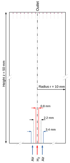
Figure 1.
2-dimensional cross section of the selected 3-dimensional geometry of the simulated domain.
The entire computational domain, as shown in Figure 1, is meshed with 41,000 nodes. Conducted mesh studies indicate that a further increase in the mesh resolution does not affect the results. For more efficient calculation, the area with the high required accuracy, such as that of the reaction zone, is more finely meshed than the area before the outlet. The conditions are based on the fact that the outer cylindrical combustion chamber is a non-enclosed space. Thus, the surface, as well as the outlet at the end of the combustion chamber, is determined to be permeable. To prevent back-flow and to exclude additional supplied air as an influence, the surfaces and the outlet are specified such that the flow can only flow out of the computational domain, but not into it. The bottom of the cylinder and the partition between the air and hydrogen supply are assumed to be walls. Separate inlets of hydrogen and air into the computational domain form, as in the case of most micro-mixer combustion systems, nozzle in nozzle system with hydrogen jet in the middle. The pressure at the walls and the inlet as well as at the outlet does not change and is set to the atmospheric ambient pressure at the surface. The temperature at the walls and the nozzle inlet is 298 K. The boundary condition for the flow velocity determines the velocity based on the specified mass flow. It thus provides a suitable tool to determine a stoichiometric ratio of the combustion at the inlet of the gases.
The discretization is based on a three-dimensional mesh. The resulting non-linear equations are solved in time using the implicit Euler method. The occurring gradients and divergences are integrated with the help of the Gaussian integral theorem and interpolated according to the linear method. The resulting system of equations is largely determined through a stabilized preconditioned bi-conjugate gradient (PBiCGStab) iteration due to the stability of the method. Only the pressure is calculated by the geometrically merged algebraic multi-grid method because of the appropriate matrix form. For , a simple preconditioned conjugate gradient method is used. For stable calculation, the Courant number is fixed at 0.5. Based on this, the time step is determined. For the determination and coupling of the pressure and velocity field, the pressure implicit with the splitting of operator (PISO) algorithm is used.
3. Results and Discussion
In the following section, the standard eddy dissipation diffusion model (EDM model) in OpenFOAM is compared with the model modified within this work (KSD model). Further, the impact of different values and power supply using the new model will be investigated.
3.1. Comparison EDM and KSD Model
Taking the higher diffusivity of hydrogen into account, the high-temperature zone shifts downstream towards the nozzle and the outer sides of the flame. An example of the influence of the selected diffusion model and its influence on the temperature distribution within the flame is given in Figure 2. While this effect is not noticeable in the results of the EDM model, the modified model can detect high-temperature risk points and predict the heat development towards the nozzle. These findings are in good agreement with the results reported in the work of Maragkos et al. [16] and Toro et al. [18].
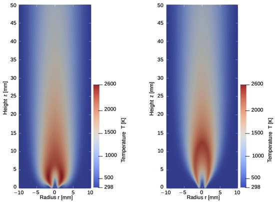
Figure 2.
Temperature distribution for the model with (left) and without (right) considering component specific diffusion.
Influence of the selected diffusion model in the temperature and mass is especially emphasized in the flame zone, close to the gas inlet. The solid line demonstrates the results from the calculation with differential diffusion while the dashed lines show the distribution of components and temperature without component-specific diffusion.
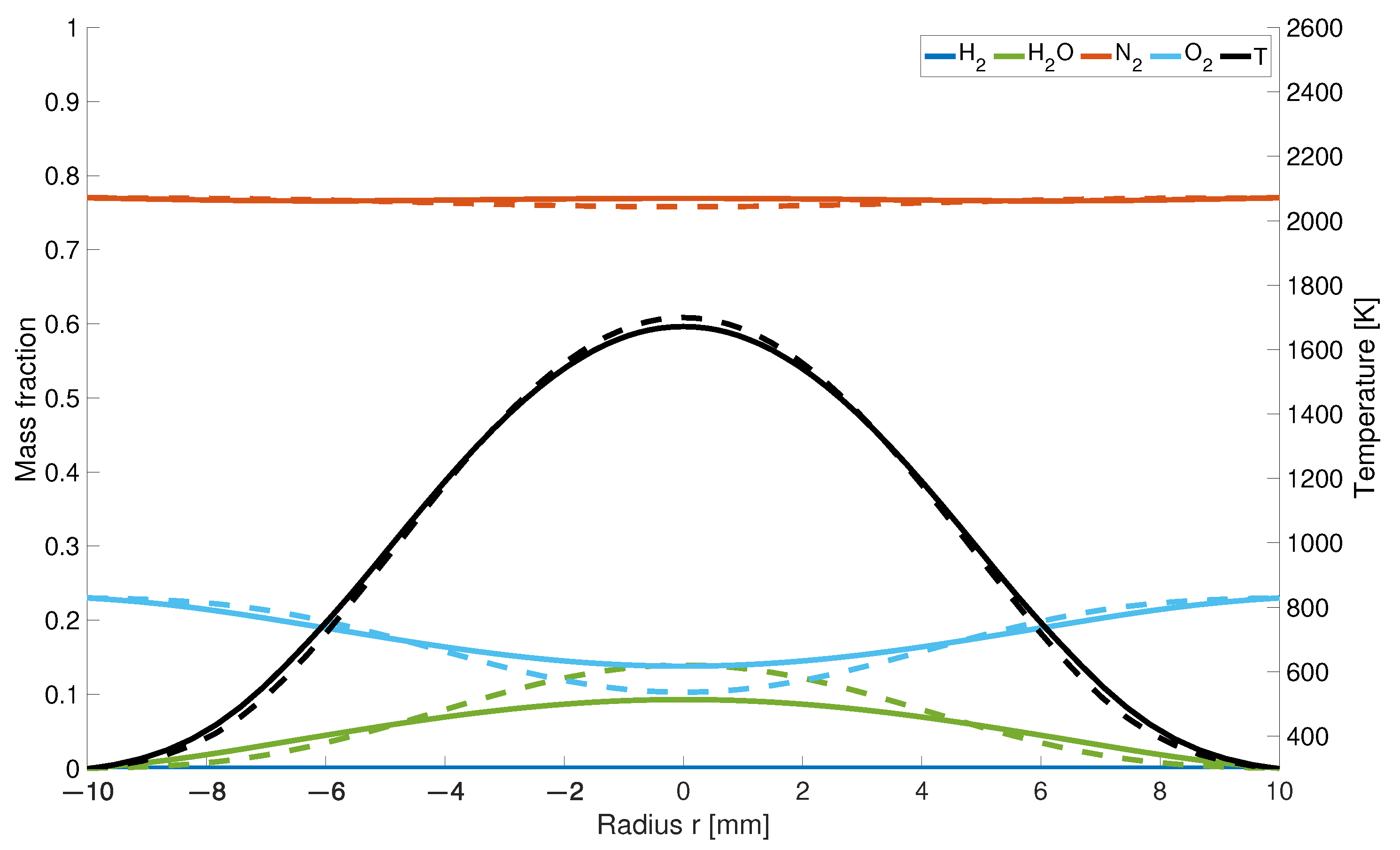
It is a general tendency that the influence of the selected diffusion model on the temperature and mass fraction distribution is reduced further upstream from the gas inlets. For example, 25 mm downstream of the gas inlet (Figure 3) only slight differences are noticeable in the case of mass fraction distribution of oxygen and water. Since for the KSD model, the hydrogen is consumed by the reaction process closer to the nozzle, the oxygen concentration is 30% higher compared to the EDM model, and therefore the ratio of water is 35% lower. The temperature distribution at this height is similar for both models.
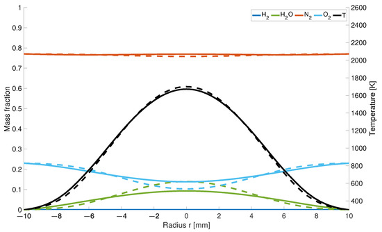
Figure 3.
Temperatur and mass fraction at a height of 25 mm; solid line: with differential diffusion, dashed line without differential diffusion.
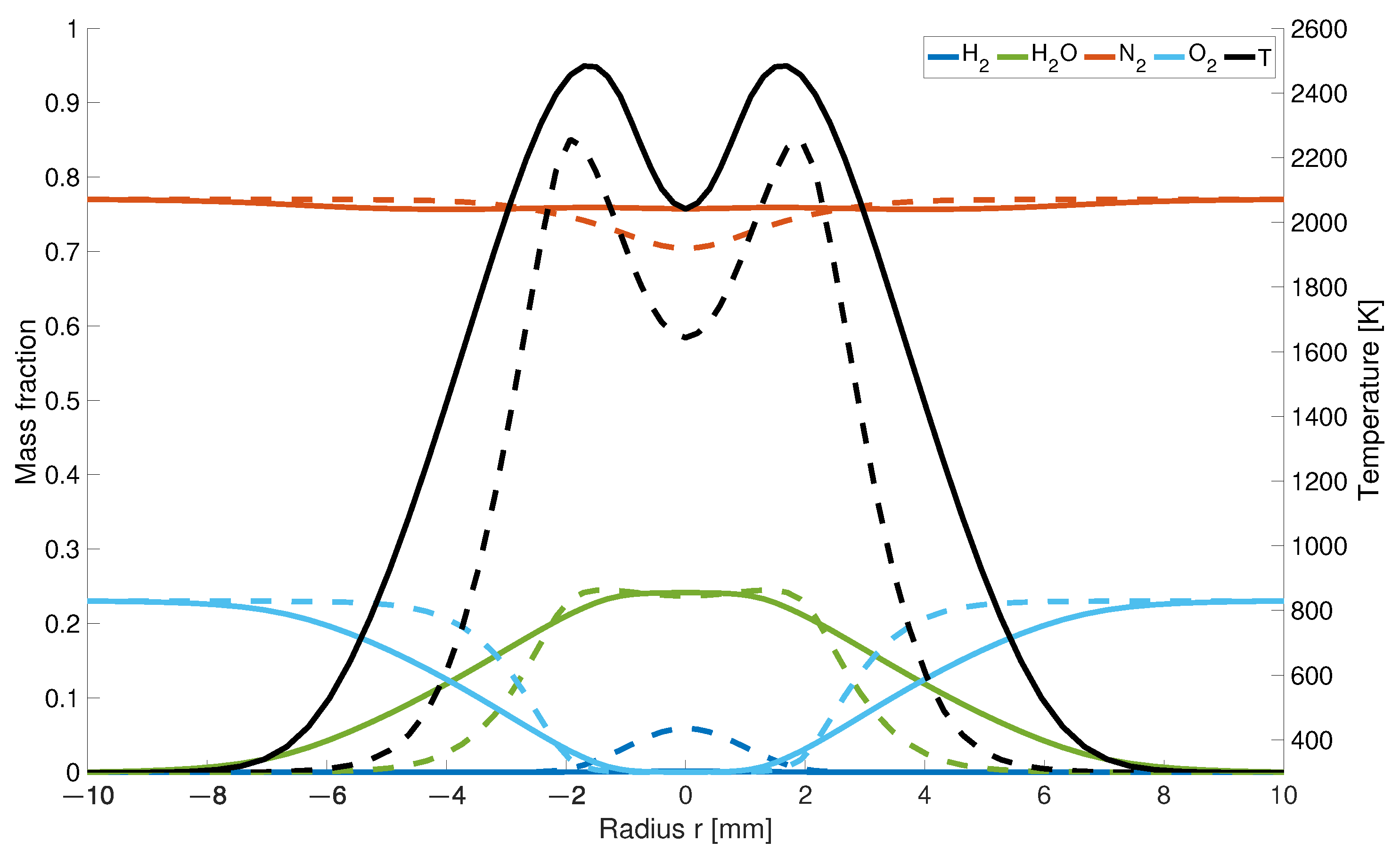
The impact of the high diffusivity of hydrogen causes higher differences as the observation plane comes closer to the gas inlet. At a 5 mm height (Figure 4), the temperature is 239 K higher and 30% wider.
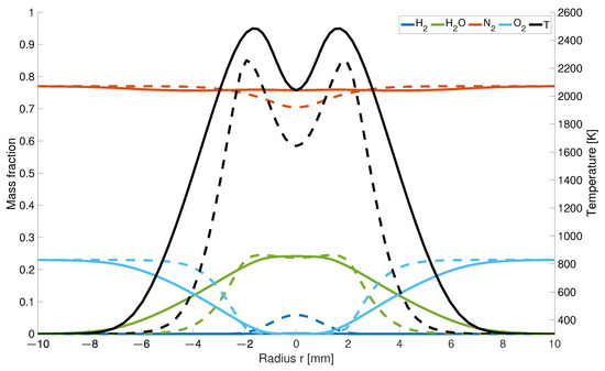
Figure 4.
Temperature and mass fraction at a height of 5 mm; solid line: with differential diffusion, dashed line without differential diffusion.
This is a result due to the fast mixing of hydrogen with air and the therefore earlier starting reaction process. While for the EDM model there is still 5% of left over, it is completely consumed for the modified calculations which are also partially responsible for the flatten curvature for the and concentration.
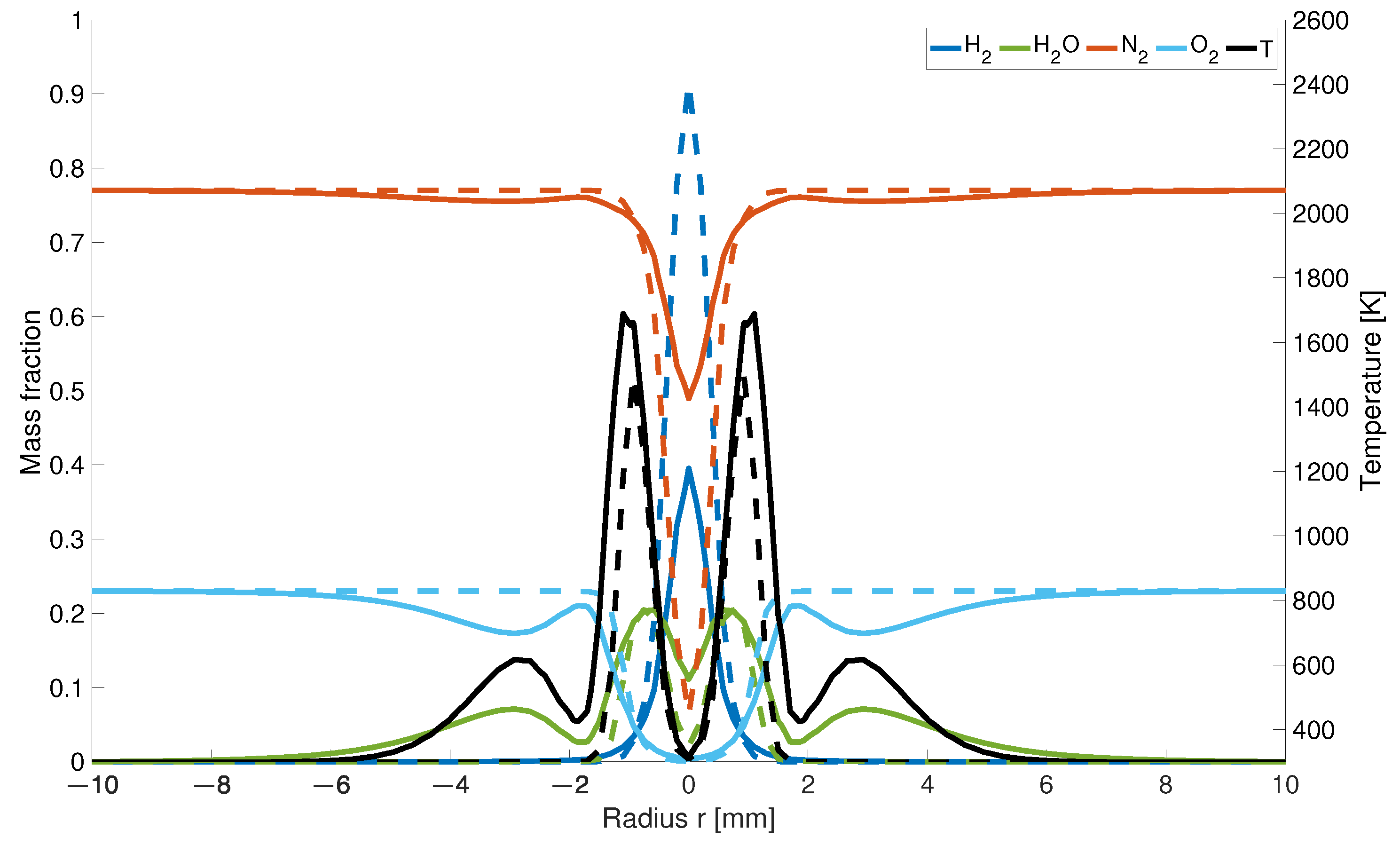
The closer the results are taken from the nozzles, the higher is also the concentration for both models. The distribution of hydrogen 0.5 mm upstream from the inlet is about 56% lower for the modified model than for the EDM model (Figure 5).
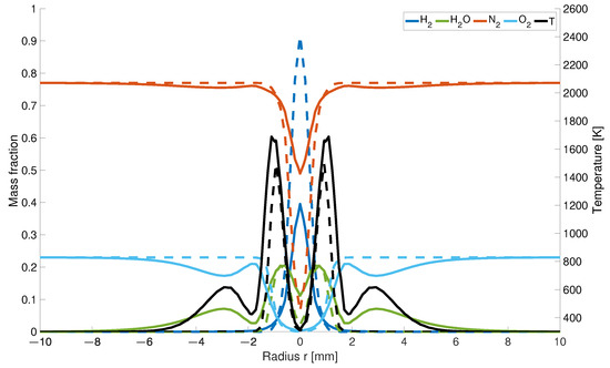
Figure 5.
Temperature and mass fraction at a height of 0.5 mm; solid line: with differential diffusion, dashed line without differential diffusion.
It is assumed that the combination of differentiated transport properties and the changed number of moles in the gas mixture affect the nitrogen mass fractions. The reduced decrease in the nitrogen concentration along the centreline is caused by the changed hydrogen distribution. While in the EDM model, hydrogen flows into the combustion chamber as a jet and displaces the existing air with a high percentage of nitrogen, diffuses away to the outside more readily in the modified model. This results in a higher concentration behind the nozzles. As the number of moles decreases during hydrogen combustion, the concentration increases in this region.
Regarding the water concentration, the result of the calculation for the KSD model differs from those obtained in previous studies. Due to the chosen nozzle diameter, the inner two maxima for both models are much closer to each other than in previous studies (Figure 5). Moreover, it is noticeable that there is a dip in the water concentration above the air inlet. The formation of the four local maxima is caused by the given air supply. According to the KSD model, the water concentration results from the faster outward diffusing hydrogen at the outer edges of the flame, which reacts earlier with the inflowing air to form water than in the EDM model. In calculation by EDM model, a hydrogen jet enclosed by the air is formed and reacts uniformly to water. The local minima caused by the inflowing cold air jet are also represented in the temperature distribution as well as a decrease in the fractions at the outer air nozzle diameter.
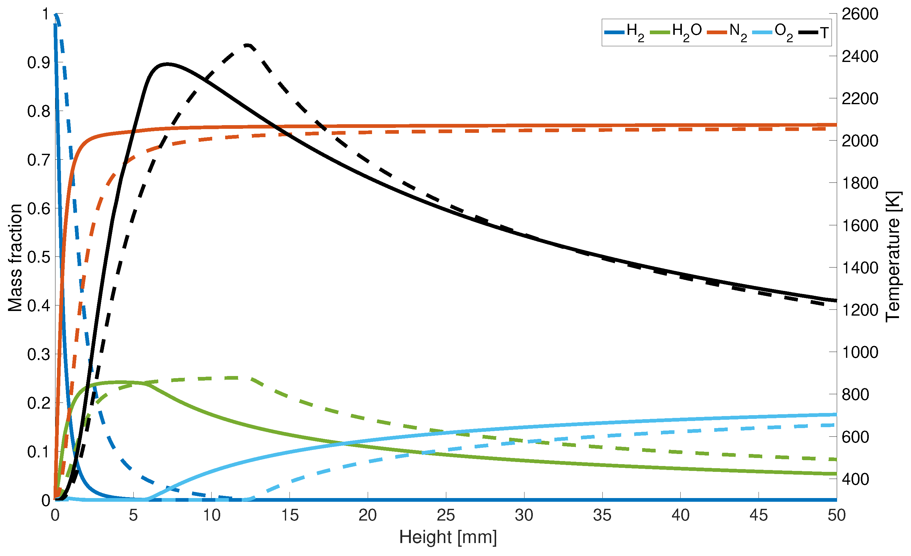
The increase in concentration and decrease of correlates with the maximum temperature along the central axis (Figure 6). Since for the KSD model the hydrogen is completely consumed at a height of 7 mm, the peak temperature is shifted downstream towards the gas inlet, whereas for the results from the EDM model, is not entirely used until a height of z = 12 mm.
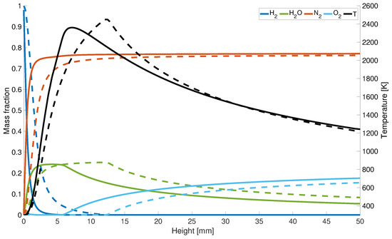
Figure 6.
Axial temperature and mass fraction distribution; solid line: with differential diffusion, dashed line without differential diffusion.
However, for completeness, it is noted that the maximum flame temperatures compared to the adiabatic flame temperature is overestimated by 4%. This could be due to the assumptions that radiation is neglected, and the adiabatic calculations lead to higher temperatures. Another possible factor can be the infinitely fast chemistry assumption. Under the selected conditions the diffusive and chemical time scales have the same order of magnitude which can lead to a deviation in the mixing and burning behavior compared to finite-rate chemistry. Last but not least the thermal diffusion impact is neglected in this study which can lead to a variance of the flame speed of up to 10% and therefore also impacts the temperature development. Both possible reasons can also lead to an over prediction of and an under prediction of at the centerline of about 20%.
3.2. Various Air-Fuel Ratios and Power Inputs
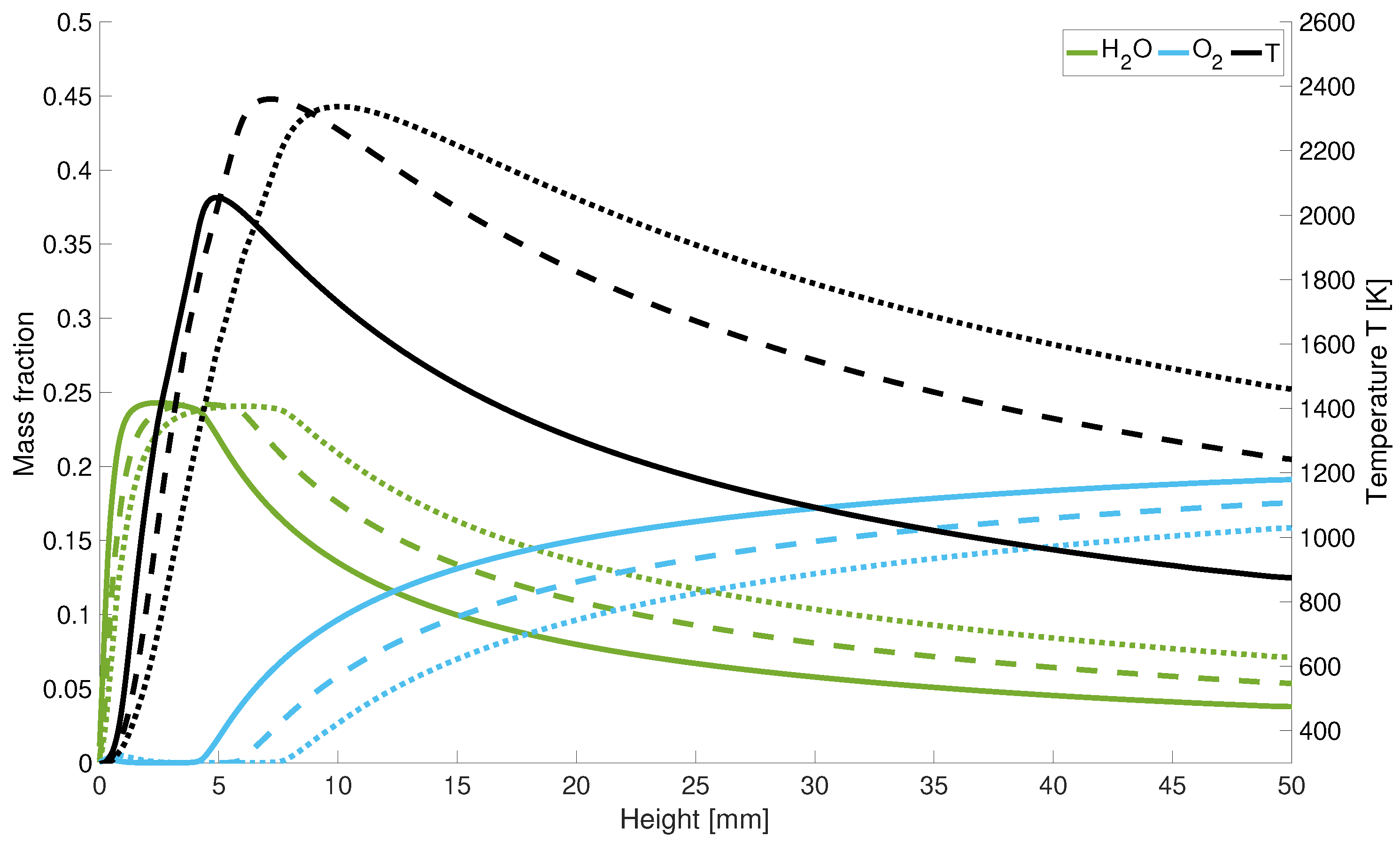
With an increase of the -values the peak temperature shifts along the centreline upstream towards the nozzle. Along the z-axis, the oxygen distribution locally increases at the nozzle inlet. Due to the high diffusivity of hydrogen, the incoming air displaces the existing hydrogen at this point (Figure 7). Further along the central axis, the oxygen is consumed during combustion and its concentration increases again behind the reaction zone.
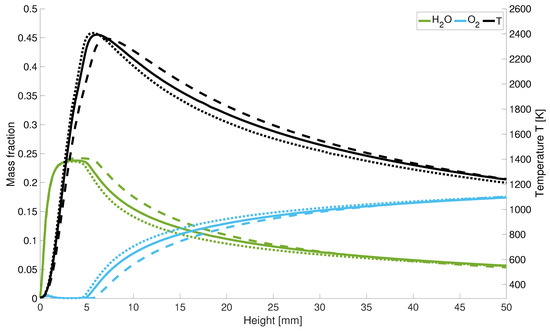
Figure 7.
Temperature and mass fraction for different ; solid line: = 1.5; dotted lines: = 2; dashed lines: = 1.
For stoichiometric combustion, the mass fraction of decreases slower than for higher values and is for = 1 at the outlet below the water concentration for lean combustion. Moreover, the oxygen fractions increase slower than for lean combustion. Therefore, for an air number of = 1, the reaction takes place closer to the inlet of the gases.
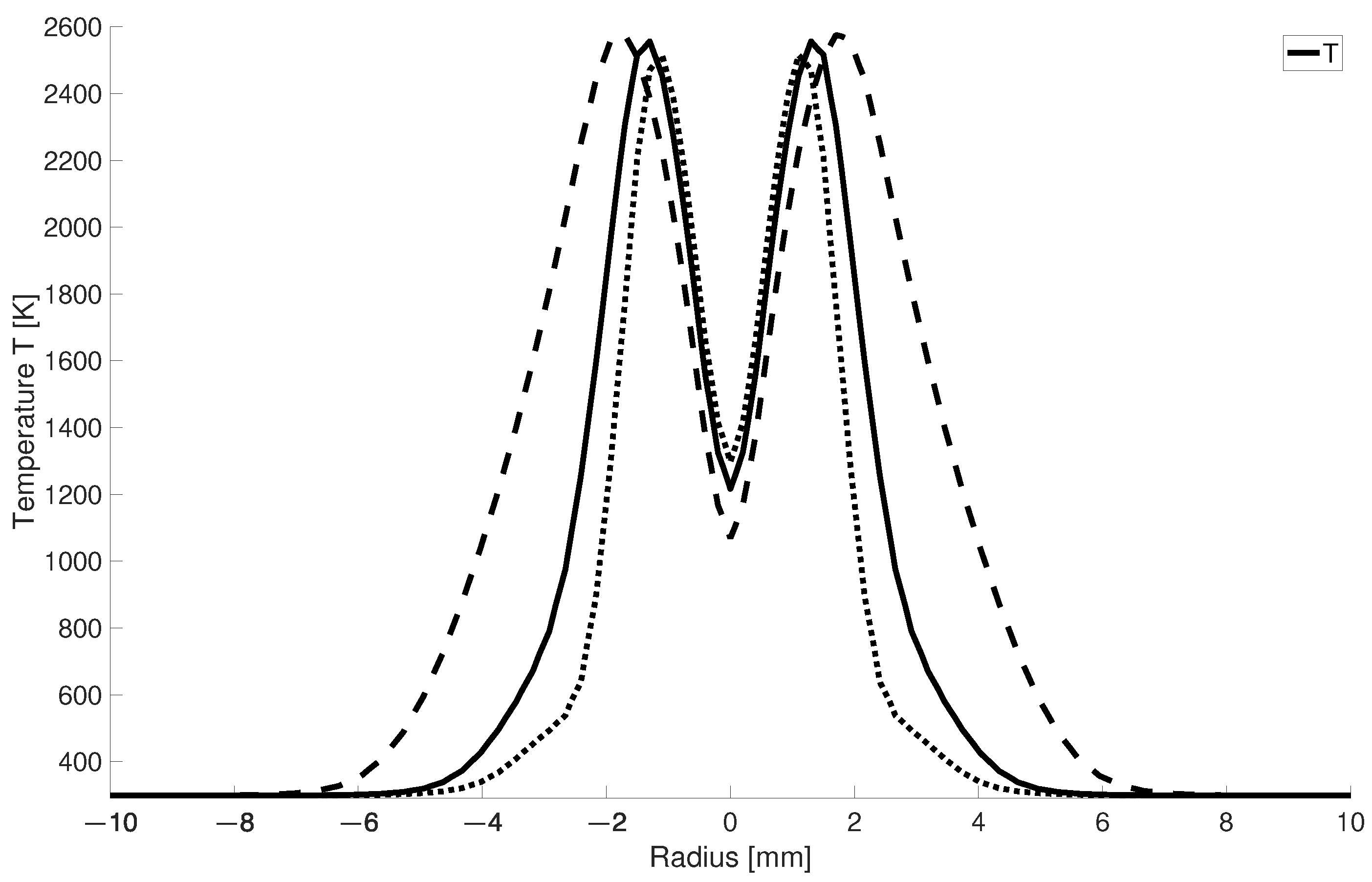
In Figure 8 it can be seen that for larger -values the high-temperature zone becomes narrower since for higher air numbers a larger mass flow of cold air is injected into the combustion chamber. This leads to the fact that for = 2, the high-temperature zone is half as wide as for stoichiometric combustion.
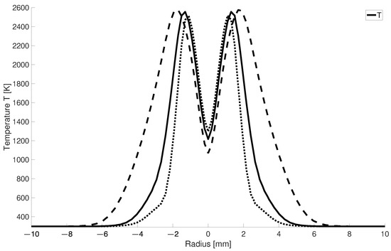
Figure 8.
Radial temperature distribution at 2.5 mm for different ; solid line: = 1.5; dotted lines: = 2; dashed lines: = 1.
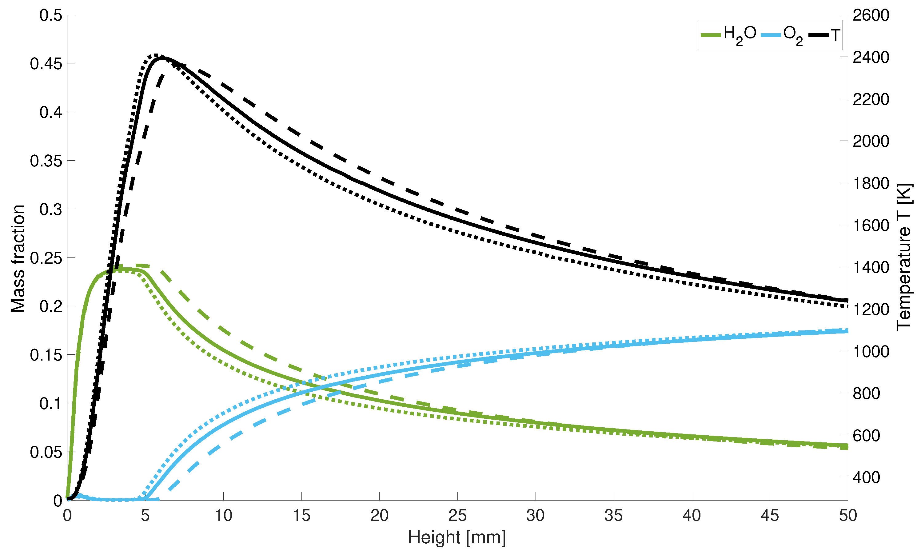
In Figure 9 it is shown that with higher powers, the length of the cold hydrogen jet is extended since the maximum temperature is shifted along the central axis. After the peak temperature, the flame temperature drops again more rapidly along the central axis for low power levels. Considering the axial course of the oxygen and water concentration in Figure 9, the quantitative scaling of the mass fractions with power input becomes clear. Further one can also observe the minimum increase of the oxygen concentration at the hydrogen nozzle inlet. It can be seen that a lower velocity leads to an earlier increase in oxygen and a faster decrease in water in the combustion chamber. Thus, a lower velocity leads speed leads to a delayed reaction overall.
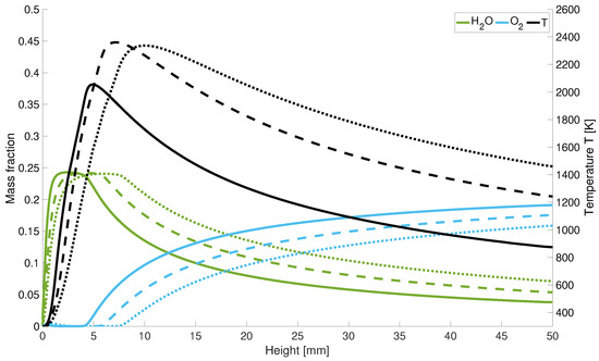
Figure 9.
Temperature and mass fraction for different input power; solid line: performance decrease; dotted lines: performance increase; dashed lines: initial power.
4. Conclusions
The results of the modified model find comparable agreement with those from previously published studies. The consideration of different diffusivities in the numerical calculation of hydrogen combustion is indispensable since the position of the high-temperature zone shifts 9.5 mm downstream towards the nozzle. Although the maximum achievable flame temperature is overestimated by about 4%, the new model nevertheless leads to a precisely local determination of the high-temperature zone. With the modified model, the positions of the high-temperature zones can be predicted in a better agreement with experimental measurements from previous studies than in the existing combustion model in OpenFOAM. Thus, a possible overheating of the nozzles and the hydrogen supply line material can be prevented. The comparison of varying -values and power shows that the air number significantly affects the flame structure and the distribution of the high-temperature zone. As the air number increases from stoichiometric combustion to , the flame width decreases by 50%. A change in the input power of ±50% leads to different temperature distribution in the entire combustion chamber and proportional varying length of the hydrogen jet. Both parameters cause a change in the reaction behavior during combustion. This paper shows that a simplified model assuming a single-step mechanism under the assumption of an infinitely fast chemistry model and a non-binary diffusion as well as without diffusion matrix gives comparable results to more complex models and can be used to determine the flame structure of hydrogen diffusion flames.
Author Contributions
Conceptualization, J.B., V.J. and A.D.; methodology, J.B. and V.J.; software, J.B.; validation, J.B. and V.J.; formal analysis, J.B., V.J. and A.D.; investigation, J.B. and V.J.; resources, V.J. and A.D.; writing—original draft preparation, J.B. and V.J.; writing—review and editing, J.B. and V.J.; visualization, J.B. and V.J.; supervision, V.J. and A.D.; project administration, V.J. and A.D.; funding acquisition, V.J. and A.D. All authors have read and agreed to the published version of the manuscript.
Funding
This research was funded by German Federal Ministry of Economy and Energy (BMWi) through the Zentrales Innovationsprogramm Mittelstand (ZIM) program (Grant Number ZF4134317AW9).
Institutional Review Board Statement
Not applicable.
Informed Consent Statement
Not applicable.
Data Availability Statement
Not applicable.
Acknowledgments
We acknowledge financial support by Deutsche Forschungsgemeinschaft and Friedrich-Alexander-Universität Erlangen-Nürnberg within the funding programme “Open Access Publication Funding”.
Conflicts of Interest
The authors declare no conflict of interest. The founding sponsors had no role in the design of the study; in the collection, analyses, or interpretation of data; in the writing of the manuscript, and in the decision to publish the results.
References
- Ghali, P.F.; Khandelwal, B. Design and Simulation of a Hydrogen Micromix Combustor. In AIAA Scitech 2021 Forum; American Institute of Aeronautics and Astronautics: Reston, Virginia, 2021. [Google Scholar] [CrossRef]
- Agarwal, P.; Sun, X.; Gauthier, P.Q.; Sethi, V. Injector Design Space Exploration for an Ultra-Low NOx Hydrogen Micromix Combustion System. In Turbo Expo: Power for Land, Sea, and Air; American Society of Mechanical Engineers: New York, NY, USA, 2019; Volume 3, p. V003T03A013. [Google Scholar] [CrossRef]
- Haj Ayed, A.; Kusterer, K.; Funke, H.W.; Keinz, J.; Striegan, C.; Bohn, D. Experimental and numerical investigations of the dry-low-NOx hydrogen micromix combustion chamber of an industrial gas turbine. Propuls. Power Res. 2015, 4, 123–131. [Google Scholar] [CrossRef] [Green Version]
- Stewart, J.R. CFD modelling of underexpanded hydrogen jets exiting rectangular shaped openings. Process Saf. Environ. Prot. 2020, 139, 283–296. [Google Scholar] [CrossRef]
- Soloklou, M.N.; Golneshan, A.A. Numerical investigation on effects of fuel tube diameter and co-flow velocity in a methane/air non-premixed flame. Heat Mass Transf. 2020, 56, 1697–1711. [Google Scholar] [CrossRef]
- Ayed, A.H.; Kusterer, K.; Funke, H.W.; Keinz, J.; Bohn, D. CFD based exploration of the dry-low-NO x hydrogen micromix combustion technology at increased energy densities. Propuls. Power Res. 2017, 6, 15–24. [Google Scholar] [CrossRef]
- Emami, S.; Jafari, H.; Mahmoudi, Y. Effects of Combustion Model and Chemical Kinetics in Numerical Modeling of Hydrogen-Fueled Dual-Stage HVOF System. J. Therm. Spray Technol. 2019, 28, 333–345. [Google Scholar] [CrossRef] [Green Version]
- Bruno, V.; Sankaran, H.; Kolla, J.C. Impact of multi-component diffusion in turbulent combustion using direct numerical simulations. Combust. Flame 2015, 11, 4313–4330. [Google Scholar] [CrossRef] [Green Version]
- Kumar, G.V.; Kampili, G.M.; Kelm, S.; Arul Prakash, K.; Allelein, H.J. Development and Verification of a Multi-Species Gas Transport Solver. In Proceedings of the 14th OpenFOAM Workshop, Duisburg-Essen, Germany, 23–26 July 2019. [Google Scholar]
- Guessab, A.; Aris, A.E.; Bounif, A.; Gokalp, I. Numerical analysis of confined laminar diffusion flame—Effects of chemical kinetic mechanisms. Int. Adv. Res. Eng. Technol. 2013, 4, 59–78. [Google Scholar]
- Wu, C.Y.; Chen, K.H. Characterization of hydrogen triple flame propagation in vitiated laminar coaxial flow. Int. J. Hydrogen Energy 2014, 39, 14109–14119. [Google Scholar] [CrossRef]
- Gruber, A.; Bothien, M.R.; Ciani, A.; Aditya, K.; Chen, J.H.; Williams, F.A. Direct Numerical Simulation of hydrogen combustion at auto-ignitive conditions: Ignition, stability and turbulent reaction-front velocity. Combust. Flame 2021, 229, 111385. [Google Scholar] [CrossRef]
- Taib, N.M.; Mansor, M.R.A.; Wan Mahmood, W.M.F. Combustion characteristics of hydrogen in a noble gas compression ignition engine. Energy Rep. 2021, 7, 200–218. [Google Scholar] [CrossRef]
- Jeon, J.; Choi, W.; Kim, S.J. A flammability limit model for hydrogen-air-diluent mixtures based on heat transfer characteristics in flame propagation. Nucl. Eng. Technol. 2019, 51, 1749–1757. [Google Scholar] [CrossRef]
- Sannan, S.; Kerstein, A.R. Differential Molecular Diffusion in a Hydrogen-Rich Jet. Energy Procedia 2016, 86, 304–314. [Google Scholar] [CrossRef] [Green Version]
- Maragkos, G.; Rauwoens, P.; Merci, B. Differential diffusion effects in numerical simulations of laminar, axi-symmetric H2/N2—Air diffusion flames. Int. J. Hydrogen Energy 2014, 39, 13285–13291. [Google Scholar] [CrossRef]
- Maragkos, G.; Rauwoens, P.; Merci, B. A new methodology to incorporate differential diffusion in CFD simulations of reactive flows. Combust. Flame 2013, 160, 1903–1905. [Google Scholar] [CrossRef] [Green Version]
- Toro, V.V.; Mokhov, A.V.; Levinsky, H.B.; Smooke, M.D. Combined experimental and computational study of laminar, axisymmetric hydrogen–air diffusion flames. Proc. Combust. Inst. 2005, 30, 485–492. [Google Scholar] [CrossRef]
- Li, J.; Huang, H.; Kobayashi, N. Hydrogen combustion as a thermal source. Energy Procedia 2017, 142, 1083–1088. [Google Scholar] [CrossRef]
- Poinsot, T.; Veynante, D. Theoretical and Numerical Combustion; R.T. Edwards, Inc.: Toulouse, France, 2012. [Google Scholar]
- Burcat, A.; Ruscic, B.; Chemistry and Technion—Israel Institute of Technology. Third Millenium Ideal Gas and Condensed Phase Thermochemical Database for Combustion (with Update from Active Thermochemical Tables); Technical Report; Israel Institute of Technology: Haifa, Israel, 2005. [Google Scholar] [CrossRef] [Green Version]
- Giacomazzi, E.; Picchia, F.R.; Arcidiacono, N. A review of chemical diffusion: Criticism and limits of simplified methods for diffusion coefficient calculation. Combust. Theory Model. 2008, 12, 135–158. [Google Scholar] [CrossRef]
- Wang, P. The model constant A of the eddy dissipation model. Prog. Comput. Fluid Dyn. Int. J. 2016, 16, 118–125. [Google Scholar] [CrossRef]


Publisher’s Note: MDPI stays neutral with regard to jurisdictional claims in published maps and institutional affiliations. |
© 2022 by the authors. Licensee MDPI, Basel, Switzerland. This article is an open access article distributed under the terms and conditions of the Creative Commons Attribution (CC BY) license (https://creativecommons.org/licenses/by/4.0/).