
Mechanical Analysis of DS in Horizontal Directional Drilling

1
School of Mechatronic Engineering, Southwest Petroleum University, Chengdu 610500, China
2
School of Civil Engineering and Geomatics, Southwest Petroleum University, Chengdu 610500, China
*
Author to whom correspondence should be addressed.
Appl. Sci. 2022, 12(6), 3145; https://doi.org/10.3390/app12063145
Submission received: 7 February 2022
/
Revised: 10 March 2022
/
Accepted: 16 March 2022
/
Published: 19 March 2022
(This article belongs to the Special Issue Geomechanics and Reservoirs: Modeling and Simulation)
Abstract
:In recent years, trenchless horizontal directional drilling (HDD) technology has developed rapidly towards the direction of large pipe diameter and long span. During construction, the buckling deformation and large drag torque of the drillstring (DS) are the key problems restricting the development of the HDD technology. In order to understand the buckling deformation law of the DS in horizontal directional drilling engineering, as well as the transfer and the distribution of the drag torque, and the relationship between the buckling deformation and drag torque, the dynamic model of the DS system in drilling engineering is applied to HDD engineering. The dynamics model of HDD at a long distance (5200 m) is established and calculated. The research indicates (1) when the buckling deformation of the DS is small, priority should be given to reducing the friction and torsion at the bending position; (2) excessive inlet thrust is the main reason for the buckling deformation of the DS, and the smaller the hole diameter, the more serious the buckling deformation; (3) severe buckling deformation of the DS will lead to an increase in the frictional resistance at the deformed part, and even local self-locking, resulting in the inability to continue to increase the weight on bit (WOB). The research results preliminarily reveal the relationship between DS buckling deformation and drag torque in ultra-long distance HDD engineering and point out the phenomenon law of drag torque and buckling deformation, which has reference value for the development of HDD technology.
1. Introduction
With the rapid development of the world economy, people’s consciousness of environmental protection is getting stronger, and their pursuit of life quality is constantly improving. The green development mode integrating urban construction and environmental protection has gradually become mainstream nowadays. In the construction of the city, due to the needs of the underground infrastructure, many pipelines need to be laid, replaced, and repaired. The traditional excavation not only causes environmental and traffic damage but also wastes time and labor force. Therefore, HDD, which has many advantages such as small environmental damage, short construction period, and high comprehensive efficiency, has been widely applied as the mainstream technology in trenchless construction and has limitless application prospects. With the continuous increase of directional crossing distance, the construction conditions are harsher, and the long and thin DS shows more and more flexibility in the long and narrow holes. The serious buckling of DS and the huge drag and torque make the drill bit unable to drilling effectively are the important reasons for limiting the breakthrough of directional drilling distance. In severe cases, DS failure may even occur (Figure 1). Therefore, it is of great significance to study the relationship between DS buckling and drag and torque of DS and its influence on WOB transfer for directional crossing development [1,2,3,4,5,6,7,8].
There are two methods to study the buckling problem of DS: Differential equations and energy methods. Lubinski et al. [9] studied the relationship between thread pitch and axial force in helical buckling of tubing using the energy method. Paslay et al. [10] obtained the critical load of sinusoidal buckling of pipe column in the inclined borehole by energy method. Chen and Lin [11] used the energy method to obtain the critical load of helical buckling of pipe columns in a horizontal well. Mitchell [12,13,14,15,16] has been doing a lot of research on the buckling problem through the differential equation. Gao [17] and Li [18] studied the buckling and post-buckling behavior of pipe columns in detail through energy method and differential equation.
On the problem of drag and torque of DS, the calculation and analysis model of drag and torque is developed on the basis of the “Soft-String Model” proposed by Johansick (1983) [19]. On the basis of large deformation theory, the effect of stiffness of drill column is considered and an improved Tension-Torque model is proposed by Ho [20]. Li and Liu [21] established the Steady-State Tension-Torque model on the basis of Ho’s model, taking into account the motion of DS and the influence of drilling fluid. Bai et al. [22,23] have proposed a beam-column theory to solve the two-dimensional force and three-dimensional force of the drill column. Liu et al. [24,25] established the longitudinal vibration model and the torsional vibration model of DS and solved them by the difference method in the numerical method. Song et al. [26] proposed a new calculation model of drag and torque. Mark [27] treated the DS system as an S-M-C (spring-mass-damping) system using the finite element method. On the basis of Hamilton’s principle, Zhu et al. [28] established the dynamic model of a three-dimension DS system with finite element method.
With the development of HDD engineering to the direction of large pipe diameter and long span, the drag torque and buckling deformation of DS is becoming more and more serious. In order to study the relationship between the friction force and deformation of DS and construction parameters in ultra-long span HDD engineering, this paper applies the DS dynamics model in the drilling engineering to HDD engineering. In this paper, the buckling and drag torque of the DS and the transmission law of WOB are calculated, which provides theoretical data support for the ultra-long span HDD engineering, and also provides help for the development of HDD engineering.
2. Model Description
Using the finite element method, the whole DS system is treated as an S-M-C system, and the problem of an infinite degree of freedom is transformed into the problem of a finite degree of freedom.
2.1. DS system Dynamics Model
In the S-M-C system mode, the DS system is simplified into a multi-degree of freedom system for analysis. Based on the basic principle of non-linear dynamics, the dynamic balance equation of the whole DS system is as follows:
Me is the mass matrix of element e; Ce is the damping matrix of element e; Pe(t) is the disturbance vector of the forced oscillation with time in element e; ue is the nodal displacement vector of element e; is the nodal velocity vector of element e; is the nodal acceleration vector of element e.
The dynamic balance equation of all the elements on the DS is set, and finally, the dynamic equilibrium equation of the whole DS system is obtained:
where M, C, and K are the mass matrix, damping matrix, and stiffness matrix of the DS system, respectively, and U, and are the generalized displacement matrix, generalized velocity matrix, generalized acceleration matrix of the DS system, respectively; F is the load matrix.
By introducing the boundary constraint and solving the equation of Equation (2) with the Wilson-θ method in step-by-step integration, the dynamic characteristics of the whole DS system can be analyzed [29].
2.2. Dynamic Calculation Model of Drag and Friction
In the borehole, the movement form of DS can be divided into two types, free movement state (Figure 2) and the contact state between DS and borehole wall (Figure 3). When the DS is not in contact with the borehole wall, the DS moves freely within the hole, and will not be subject to the constraint force given by the hole wall. At this point the DS is in free motion; when the DS surface is close to the borehole wall and there is a tendency to move out of the borehole, the movement is bound by the borehole wall. Subsequently, the DS collides with the borehole wall and produces contact force and friction. When the DS is in contact with the borehole wall, the normal contact reactionary force fn is generated at the contact position. In addition, tangential friction force fτ and axial friction force f are generated at the contact point.
The contact element between DS and borehole wall is constructed, and the thickness of the contact element is assumed to be 0.001 m [30]. Then, the interaction distance between DS and borehole wall can be obtained by Equation (3).
where r is the approaching distance between the DS and the borehole wall; rd is the radial displacement of the DS element; Rw is the diameter of the borehole;
The hertzian contact theory is used to calculate the contact force between DS and borehole wall at the contact point. Assuming that the resistance factor of rock and DS is k and the damping coefficient is c, the interaction between DS and borehole wall can be obtained by Equation (4).
where Fn is the contact force; vr is the radial velocity at the DS element.
Based on the Coulomb friction theorem, the friction generated at the contact point is calculated by Equations (5) and (6).
where f, u, and v are the axial friction force, axial friction coefficient, and axial velocity, respectively, and fτ, uτ, and vτ are the tangential friction force, tangential friction coefficient and tangential velocity, respectively.
3. Simulation Method and Experimental Verification
Using ABAQUS finite element pretreatment module, a three-dimensional finite element model was established. Drill bit, DS, borehole, and rock were modeled by rigid body shell element R3D4, spatial two nodes beam element BEAM31, rigid body shell element R3D4, and three-dimension solid element C3D8R, respectively, by the meshing techniques (Figure 4). Make the following hypothesis:
(1) In the analysis process, the DS is in line elastic state without considering plastic deformation.
(2) Ignore the impact of DS joints.
(3) The axis of the DS coincides with the axis of the borehole when the DS is not under gravity.
(4) The borehole wall is rigid and does not deform when contacting the DS.
(5) The weight of the DS is constant.
The boundary conditions in the model are shown in Figure 5, and are mainly composed of three parts:
(1) Apply axial force and rotational speed on the DS nodes at the entrance;
(2) A free border is used at the bottom. The bit can freely cut the bottom rock;
(3) The range of motion of the DS is limited to the inside of the hole, and the wall of the hole is constrained by fixed constraints in global coordinates.
The principle of HDD is consistent with that of directional drilling in drilling engineering. Therefore, the reliability of the model can be verified by comparing the measured data of drilling engineering with the simulation results. In order to evaluate and analyze the reliability of the model, the actual drilling data is obtained through field drilling measurements, and the obtained data is compared with the simulated calculation data in Figure 6 and Figure 7. The boundary condition set in the simulation is ideal, which is different from the real drilling. Therefore, the small error is reasonable and acceptable.
By comparing the measured torque and the simulated torque, as well as the measured WOB and the simulated WOB, the reliability of the calculation results of the DS dynamics model is verified.
3.1. Torque Comparison Results
The measured torque fluctuation curve of the well (the well number is NP43-4006) is shown in Figure 6a. The numerical model under the same condition as that of the well is established through the drilling string dynamics, and the torque fluctuation curve shown in Figure 6b is obtained after calculation.
- (1)
- The average value of measured torque was 3.29 kN·m, and the average value of calculated torque was 3.37 kN·m. The error between them was 2.43%.
- (2)
- The standard deviation of measured torque was 0.337 kN·m, and the standard deviation of calculated torque was 0.346 kN·m. The error between them was 2.67%.
When the simulation model is established, the borehole wall is assumed as a rigid body to ensure calculation efficiency. This was not consistent with the actual situation. However, the error was less than 3%, which was an acceptable range.
3.2. WOB Comparison Results
The measured WOB fluctuation curve of well np43-4006 is shown in Figure 7a, and the calculated WOB fluctuation curve of the well is shown in Figure 7b.
- (1)
- The average value of the measured WOB was 135.77 KN, and the average value of the calculated WOB was 137.25 KN. The error between them was 1.10%.
- (2)
- The standard deviation of measured WOB was 8.15 KN, and the standard deviation of calculated WOB was 7.92 KN·m. The error between them was −2.80%.
This error was the same as the error described in Section 3.1, and it was an unavoidable error between the ideal model and the actual condition. As the error was less than 3%, which was an acceptable range, this model can be used for the next calculation.
4. Analysis and Application of Engineering Case
In the project of the pipeline crossing 5200 m rock strata, the DS dynamics model of the construction stage of the pilot hole and the reaming is established and calculated. where borehole trajectory, boundary conditions, bottom hole assembly are shown in Figure 8a,b and Figure 9. Table 1 and Table 2 are the required material properties to calculate.
4.1. Calculation Results of Buckling of DS
By introducing the boundary conditions of the pilot hole and calculating the DS dynamics, the movement and deformation of the DS were clearly obtained. When the thrust force is 10T, 20T, and 30T, the displacement cloud diagram of DS is shown in Figure 10a–c. In Figure 10a, the DS is in a stable state immediately below the borehole, has no buckling. In Figure 10b, the DS is below the borehole and showed sinusoidal buckling. In Figure 10c, the DS shows obvious helical buckling.
4.2. The Construction Stage of the Pilot Hole
The 12-1/4in drill bit is used in the construction stage of the pilot hole. The construction method of drilling from both ends to the middle is adopted, and the DS dynamics model of 3200 m on the entrance side is established with the actual working condition parameters. The thrust force is 20T, 30T, and 40T, and the model is calculated respectively. The x and y directions are defined as shown in Figure 11. Finally, the spatial displacement distribution of DS is shown in Figure 12.
When the thrust force is 20T, the spatial displacement distribution of the horizontal DS is shown in Figure 12a. The displacement of the DS from the end of the building up section to the drill bit fluctuated less in the y direction with a amplitude of 25 mm. Due to the influence of DS size, the displacement in the y direction changed markedly at the connection position of different types of DS, such as the position at 1200 m and the position at 2600 m. The x direction DS had obvious sinusoidal buckling fluctuation in many places, with a peak value of 105 mm. In summary, when the thrust force was 20T, sinusoidal buckling of the DS occurred and is located below the borehole.
When the thrust force increases to 30T, helical buckling first appeared on the 6-5/8in DS in the horizontal section, as shown in Figure 12b. The displacement of the DS in the direction-direction fluctuated significantly, and the DS adhered to the borehole wall at both ends of the 6-5/8in DS, resulting in obvious helical buckling. The displacement amplitude of the DS on the entrance side was 50 mm in the direction-direction and 150 mm in the direction-direction. The displacement amplitude of the DS on the drill bit side is 40 mm in the direction-direction and 120 mm in the direction-direction. Helical buckling occurred in some DSs, resulting in a significant increase in the DS’s drag and torque, which made axial force and torque not effectively transmitted to the drill bit. The bit’s rock-breaking efficiency decreased. Drilling assembly needs to be optimized, such as adding stabilizers to the buckling position.
When the thrust force is 40T, the buckling degree of DS continues to increase. At this time, the 7-5/8in DS on the left side of the horizontal segment also presented significant helical buckling (Figure 12c). However, there is no helical buckling in the right 5-1/2in DS. The reason is that the left DS had severe helical buckling, which led to the failure of drilling pressure to transfer effectively to the right DS so that the axial force of the right DS did not reach the critical value of helical buckling. The displacement of the DS in the borehole can be seen intuitively from Figure 12c. The inner-circle represented the helical buckling of the 7-5/8in DS, the outer circle represented the helical buckling of the 6-5/8in DS, and the lower arc represented the sinusoidal buckling of the 5-1/2in DS.
The distribution of DS contact force and DS torque is shown in Figure 13. As can be seen from the DS displacement distribution in Figure 12, when the thrust force is 20T, sinusoidal buckling deformation occurred to DS of various sizes. When the thrust is 30T or 40T, the obvious spiral buckling deformation is shown in DS. This will definitely affect the contact force between the DS and the borehole wall.
When the thrust is 20T, the contact force between the DS and the borehole wall is not evenly distributed at the position where the sinusoidal buckling deformation occurred. At this point, the average contact force of each DS node is less than 2 kN, and the contact force at the part where no deformation occurs is only 0.65 kN. When the thrust is 30T, the contact force of each drill strig node reached up to 6 kN.
When the thrust force is 20T, the maximum torque of the DS is 38 kN·m. When the thrust is 30T, the maximum torque of the DS is 36 kN·m. When the thrust is 40T, the DS buckled, and the maximum torque of the DS is 68 kN·m.
4.3. The Construction Stage of the Reaming
The construction stage of the reaming is divided into two forms, the first is the reaming method of the backhaul DS and the second is the reaming method (similar to pilot hole) by drilling in the middle at both ends. The second method is more suitable for hard formation reaming.
In the first stage of reaming, the spatial displacement distribution of DS is shown in Figure 14a. At this point, the thrust force is 30T. It can be seen from the displacement diagram that obvious spiral buckling occurred on the left side of the 7-5/8in drill pipe and on the right side of the 6-5/8in the drill pipe. In the secondary reaming, the spatial displacement distribution of the DS is shown in Figure 14b, and the thrust is 40T. Due to the increase of bore size, the spiral buckling of some DS in the hole is no longer complete (the DS is not attached to the borehole wall). The DS with complete spiral buckling is concentrated near the entrance of the DS of various sizes. In the third-stage reaming, the spatial displacement distribution of the DS is shown in Figure 14c, and the thrust is still 40T. At this point, 7-5/8in DS no longer produces spiral buckling, but sinusoidal buckling near the entrance. The 6-5/8in DS is still marked by spiral buckling near the entrance.
In the reaming operation, the contact force distribution and the torque distribution of DS are shown in Figure 15. As can be seen from the figure, as the bore size increases, the contact force between the DS and the borehole wall gradually decreases. In the third-stage reaming, the contact force of the back part of the DS becomes stable, because there is no buckling deformation of the DS.
5. Engineering Application
During the reaming stage of the HDD engineering of YangBa mountain, when the 147th DS (6-5/8in) is drilling 2 m, the mud pressure and torque suddenly dropped to zero. It is speculated that the DS is broken, and the broken DS was found when the DS was pulled back to the 137th DS (see Figure 1). According to the field analysis, there are two main reasons for DS fracture:
1. The size of DS is small, and its torsion resistance is low.
2. The drag torque between DS and borehole wall is large.
In the dynamic simulation results, it is found that in the ultra-long span HDD project, the drill string is prone to buckling deformation, which is caused by the small size of the drill string and its poor torsional resistance. The large drag torque mentioned in the case corresponds to the conclusion in the previous article: the buckling deformation of the drill string leads to the above contact friction and even self-locking. Therefore, based on the rules and conclusions obtained in this paper, the DS after the 130th is replaced by a 7-5/8-inch DS on site, and some stabilizers are installed in the bending section to reduce the contact drag torque of the DS. Finally, the HDD project with a horizontal length of 1705.4 m (the total length is 1718.2 m) was successfully completed.
6. Conclusions
1. Taking the directional crossing engineering, for example, the dynamic model of the DS and the dynamic characteristic of the DS system are simulated and calculated to obtain the real-time variation law of the deformation and drag and torque of the DS, and successfully guide the yangba mountain crossing project.
2. In the operation of the guide hole, when the entrance thrust is too large (greater than 30T), the DS occurred spiral buckling, which greatly increased the contact force between the DS and the hole wall. The DS friction increased sharply, and the drill pressure transfer is difficult. The results show that the smaller inlet thrust, or the preselected larger DS could prevent the spiral buckling of the DS.
3. Through calculation, it founds that the third-stage reaming operation and the pilot hole operation with the thrust of 20T, when the DS without buckling or buckling deformation is relatively small, the contact between the DS and the borehole wall is the most serious at the bending section (the contact force at the bending section was more than 1/3 higher than the contact force at the horizontal section). At this point, the drag and torque of DS were the fastest. When the buckling deformation of the DS is relatively small, the friction and drag reduction of the DS at the bend should be ensured first.
4. The relationship between the buckling deformation and the contact force of the DS is studied by the calculation of the DS dynamics:
(1) After sinusoidal buckling occurred to the DS, the contact force between the DS and the borehole wall increased obviously and the contact position and contact force size distribution is no longer uniform. This phenomenon was more obvious when the DS occurred spiral buckling.
(2) Severe spiral buckling led to self-locking of DS, then the transfer efficiency of WOB is reduced. Continue to increase the thrust force, the WOB would not increase.
Author Contributions
Conceptualization, Y.S.; Data curation, Y.S.; Methodology, H.T.; Validation, H.T.; Writing—review & editing, H.T. All authors have read and agreed to the published version of the manuscript.
Funding
This research received no external funding.
Conflicts of Interest
The authors declare no conflict of interest.
References
- Zhu, X.; Yi, Q. Research and application of reaming subsidence control in horizontal directional drilling. Tunn. Undergr. Space Technol. 2018, 75, 1–10. [Google Scholar] [CrossRef]
- Zhu, X.; Liu, Y. Vibration characteristics analysis of reamer drilling in the soft and hard sandwiching. J. Vib. Meas. Diagn. 2016, 36, 915–921. [Google Scholar]
- Jia, Y.; Jiang, P.; Zhu, X.; Zhang, Y. Nonlinear Buckling Simulation of Drillstring System During Pilot Hole Drilling in Horizontal Directional Drilling. J. Syst. Simul. 2013, 25, 821–825. [Google Scholar]
- Tervydis, P.; Jankuniene, R. Horizontal directional drilling pilot bore simulation. Turk. J. Electr. Eng. Comput. Sci. 2017, 25, 3421–3434. [Google Scholar] [CrossRef]
- Lan, H.; Ma, B.; Shu, B.; Wu, Z. Prediction of rotational torque and design of reaming program using horizontal directional drilling in rock strata. Tunn. Undergr. Space Technol. 2011, 26, 415–421. [Google Scholar] [CrossRef]
- Ariaratnam, S.T.; Botteicher, R.; Ghosh, A.; Piratla, K.; Vilfrant, E. Predictive modeling of installation loads for directional drilled fusible PVC pipe. Tunn. Undergr. Space Technol. 2010, 25, 766–772. [Google Scholar] [CrossRef]
- Kan, D.; Wei, W.; Chung, Y. Discrete element modelling of stress-induced instability of directional drilling boreholes in anisotropic rock. Tunn. Undergr. Space Technol. 2018, 81, 55–67. [Google Scholar]
- Wang, X.; Sterling, R.L. Stability analysis of a borehole wall during horizontal directional drilling. Tunn. Undergr. Space Technol. 2007, 22, 620–632. [Google Scholar] [CrossRef]
- Lubinski, A.; Althouse, W.S. Helical buckling of tubing sealed in packers. J. Pet. Technol. 1962, 14, 655–670. [Google Scholar] [CrossRef]
- Paslay, P.R.; Bogy, D.B. The stability of a circular rod laterally constrained to be in contact with an inclined circular cylinder. J. Appl. Mech. 1964, 31, 605–610. [Google Scholar] [CrossRef]
- Chen, Y.; Lin, Y. Tubing and casing buckling in horizontal wells (includes associated papers 21,257 and 21,308). J. Pet. Technol. 1990, 42, 140–141. [Google Scholar] [CrossRef]
- Mitchell, R.F. Effects of well deviation on helical buckling. SPE Drill. Completion 1997, 12, 63–70. [Google Scholar] [CrossRef]
- Mitchell, R.F. A buckling criterion for constant-curvature wellbores. SPE J. 1999, 4, 349–352. [Google Scholar] [CrossRef]
- Mitchell, R.F. Helical buckling of pipe with connectors in vertical wells. SPE Drill. Completion 2000, 15, 162–166. [Google Scholar] [CrossRef]
- Mitchell, R.F. Lateral buckling of pipe with connectors in horizontal wells. SPE J. 2003, 8, 124–137. [Google Scholar] [CrossRef]
- Mitchell, R.F. The effect of friction on initial buckling of tubing and flowlines. Spe Drill. Completion 2007, 22, 112–118. [Google Scholar] [CrossRef]
- Gao, D. Down-Hole Tubular Mechanics and Its Applications; China University of Petroleum Press: Beijing, China, 2006. [Google Scholar]
- Li, Z. Tubular Mechanics in Oil-Gas Wells and Its Applications; Petroleum Industry Press: Beijing, China, 2008. [Google Scholar]
- Johancsik, C.A.; Friesen, D.B.; Dawson, R. Torque and drag in directional wells-prediction and measurement. J. Pet. Technol. 1984, 36, 987–992. [Google Scholar] [CrossRef]
- Ho, H.S. An improved modeling program for computing the torque and drag in directional and deep wells. In Proceedings of the SPE Annual Technical Conference and Exhibition, Houston, TX, USA, 2–5 October 1988; Society of Petroleum Engineers: Houston, TX, USA, 1988. [Google Scholar]
- Li, Z.; Liu, X. Steady state tubing string tension-torque physical models and its application for drill stem in Horizontal Well. Pet. Drill. Tech. 1992, 20, 1–6. [Google Scholar]
- Bai, J.; Lin, X. Two-dimensional analysis of bottom hole assembly by beam-column theory. Acta Pet. Sin. 1985, 3, 75–84. [Google Scholar]
- Bai, J.; Huang, H.; Liu, Y. Three-dimensional analysis of bottom hole assembly by beam-column theory. Acta Pet. Sin. 1989, 2, 60–66. [Google Scholar]
- Liu, Q.; Ma, D.; Tang, X. The method of solution and establishment for axial vibration model of drilling string. J. Southwest Pet. Inst. 1998, 20, 55–58. [Google Scholar]
- Liu, Q.; Ma, D.; Zhong, Q.; Qing, Z. A drilling string torsional vibration model and its solution. Acta Pet. Sin. 2000, 21, 78–82. [Google Scholar]
- Song, Z.; Gao, D.; Ma, J. New model for forecasting drag and torque in extended reach well. Oil Drill. Prod. Technol. 2006, 28, 1–3. [Google Scholar]
- Dykstra, M.W. Nonlinear Drillstring Dynamics. Ph.D. Thesis, The University of Tulsa, Tulsa, OK, USA, 1996. [Google Scholar]
- Zhu, X.; Liu, Q.; Tong, H. Research on dynamics model of full hole drilling-string system with three-dimensional trajectory. Acta Pet. Sin. 2008, 29, 288. [Google Scholar]
- Zhu, X.; Jia, Y.; Tong, H. Vibrating characteristics of Drillstring in gas drilling and its control measures. Acta Petrol. Sin. 2012, 33, 293–297. [Google Scholar]
- Zhu, X.; Li, B.; Liu, Q.; Chang, X.; Li, L.; Zhu, K.; Xu, X. New analysis theory and method for drag and torque based on full-hole system dynamics in highly deviated well. Math. Probl. Eng. 2015, 2015, 535830. [Google Scholar] [CrossRef] [Green Version]
Figure 1.
The failure of DS. (a) Partial enlargement. (b) Panorama.

Figure 2.
Free movement state.

Figure 3.
Contact state.

Figure 4.
Meshing. (a) Rock. (b) Drill bit. (c) Borehole. (d) DS.

Figure 5.
Boundary conditions.

Figure 6.
Compare measured torque and calculated torque. (a) The measured torque. (b) The calculated torque.
Figure 6.
Compare measured torque and calculated torque. (a) The measured torque. (b) The calculated torque.


Figure 7.
Compare measured WOB and calculated WOB. (a) The measured WOB. (b) The calculated WOB.

Figure 8.
The trajectory and size of the borehole. (a) Construction stage of the pilot hole. (b) Construction stage of the reaming.
Figure 8.
The trajectory and size of the borehole. (a) Construction stage of the pilot hole. (b) Construction stage of the reaming.


Figure 9.
Boundary conditions.

Figure 10.
Three degrees of DS deformation (Unit: m). (a) The DS did not buckle. (b) The DS showed sinusoidal buckling. (c) The DS showed helical buckling.
Figure 10.
Three degrees of DS deformation (Unit: m). (a) The DS did not buckle. (b) The DS showed sinusoidal buckling. (c) The DS showed helical buckling.


Figure 11.
Coordinate system.
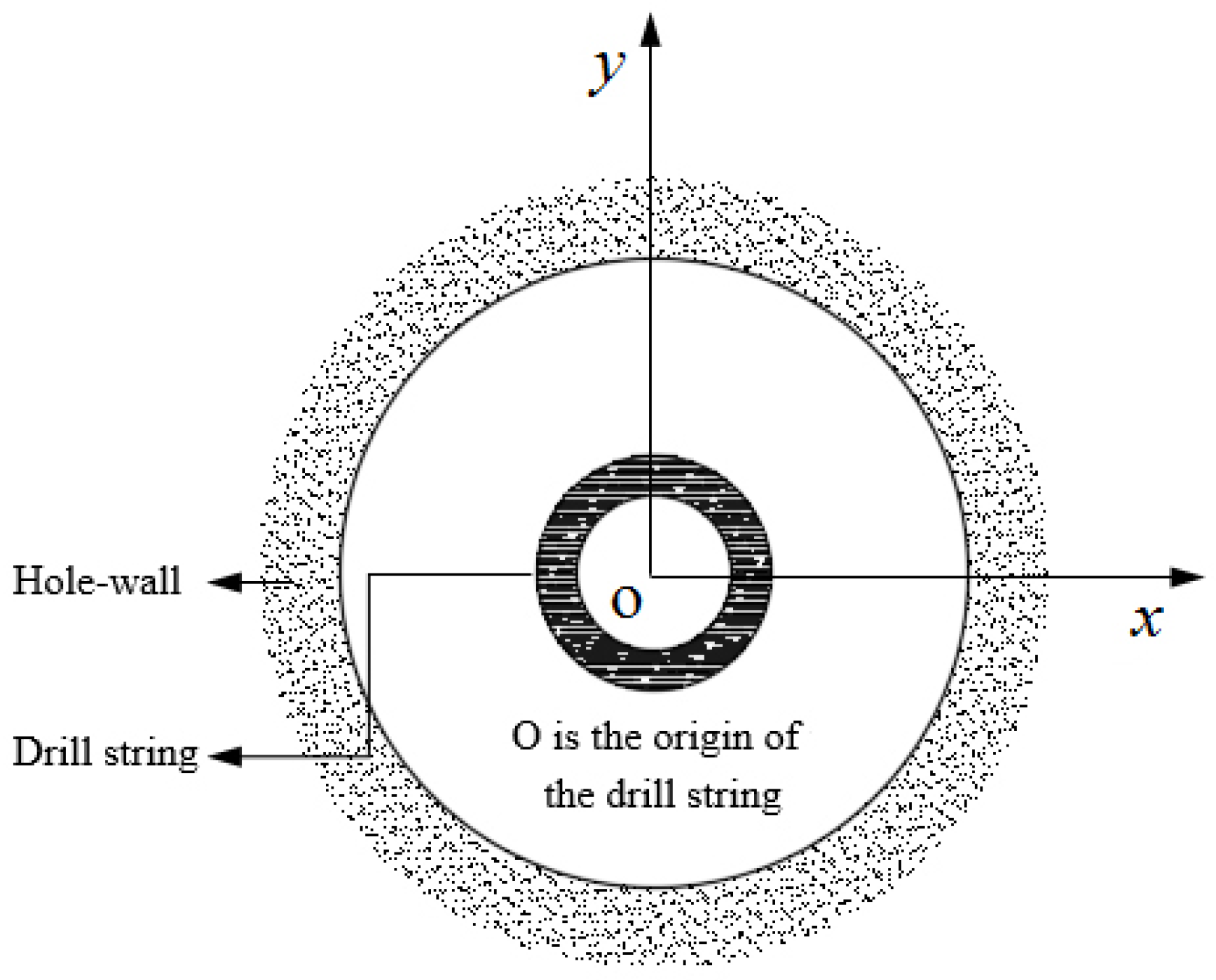
Figure 12.
The spatial displacement distribution of DS. (a) The thrust force is 20T. (b) The thrust force is 30T. (c) The thrust force is 40T.
Figure 12.
The spatial displacement distribution of DS. (a) The thrust force is 20T. (b) The thrust force is 30T. (c) The thrust force is 40T.


Figure 13.
DS contact force and torque distribution. (a) 20T. (b) 30T. (c) 40T.

Figure 14.
Displacement distribution of DS. (a) The first stage reaming. (b) The second stage reaming. (c) The third stage reaming.
Figure 14.
Displacement distribution of DS. (a) The first stage reaming. (b) The second stage reaming. (c) The third stage reaming.

Figure 15.
The contact force distribution and torque distribution of DS. (a) The first stage reaming. (b) The second stage reaming. (c) The third stage reaming.
Figure 15.
The contact force distribution and torque distribution of DS. (a) The first stage reaming. (b) The second stage reaming. (c) The third stage reaming.


Table 1.
Bottom hole assembly.
| Construction Stage | Position (m) | Drilling Tool | Weight (Kg/m) | Inner Diameter (mm) | Outer Diameter (mm) |
|---|---|---|---|---|---|
| Pilot hole | Entrance-800 | 7-5/8in Drill pipe | 63.75 | 171.83 | 193.7 |
| 800–2300 | 6-5/8in Drill pipe | 58.42 | 146.46 | 168.3 | |
| 2300–3180 | 5-1/2in Drill pipe | 33.57 | 139.7 | 118.6 | |
| 3180–3190 | 8in Drill collar | 223.5 | 71.40 | 203.2 | |
| 3190–3200 | Mud motor | ||||
| 3200 | 12-1/4in Drill bit | ||||
| First stage reaming | Entrance-1000 | 7-5/8in Drill pipe | 63.75 | 171.83 | 193.7 |
| 1000–2500 | 6-5/8in Drill pipe | 58.42 | 146.46 | 168.3 | |
| 2500 | 24in Rock reamer | ||||
| Secong stage reaming | Entrance-1000 | 7-5/8in Drill pipe | 63.75 | 171.83 | 193.7 |
| 1500–3000 | 6-5/8in Drill pipe | 58.42 | 146.46 | 168.3 | |
| 3000 | 34in Rock reamer | ||||
| Third stage reaming | Entrance-1000 | Drill pipe (A) | 63.75 | 171.83 | 193.7 |
| 1500–3000 | Drill pipe (B) | 58.42 | 146.46 | 168.3 | |
| 3000 | 42in Rock reamer | ||||
Table 2.
Material Properties.
| Object | Poisson’s Ratio | Elasticity Modulus (MPa) | Dilation Angle (°) | Cohesion Stress (MPa) | Frictional Angle (°) |
|---|---|---|---|---|---|
| Rock | 0.111 | 31,200 | 25.02 | 39.24 | 27.61 |
| Drill pipe | 0.30 | 210,000 | |||
| Drill collar | 0.30 | 210,000 | |||
| Bit and reamer | 0.26 | 206,000 | |||
Publisher’s Note: MDPI stays neutral with regard to jurisdictional claims in published maps and institutional affiliations. |
© 2022 by the authors. Licensee MDPI, Basel, Switzerland. This article is an open access article distributed under the terms and conditions of the Creative Commons Attribution (CC BY) license (https://creativecommons.org/licenses/by/4.0/).
Share and Cite
MDPI and ACS Style
Tong, H.; Shao, Y. Mechanical Analysis of DS in Horizontal Directional Drilling. Appl. Sci. 2022, 12, 3145. https://doi.org/10.3390/app12063145
AMA Style
Tong H, Shao Y. Mechanical Analysis of DS in Horizontal Directional Drilling. Applied Sciences. 2022; 12(6):3145. https://doi.org/10.3390/app12063145
Chicago/Turabian StyleTong, Hua, and Yongbo Shao. 2022. "Mechanical Analysis of DS in Horizontal Directional Drilling" Applied Sciences 12, no. 6: 3145. https://doi.org/10.3390/app12063145
Note that from the first issue of 2016, this journal uses article numbers instead of page numbers. See further details here.