1. Introduction
With the increasing employment of aspheric and free forms with high surface form accuracy, low surface roughness, and free defects, a number of classical deterministic sub aperture polishing techniques have been developed [
1,
2,
3]. Examples include, but are not limited to, small tool polishing [
4,
5,
6], stressed-lap polishing [
7,
8], magnetorheological finishing [
9,
10,
11], bonnet polishing [
12,
13,
14,
15,
16,
17], ion beam figuring [
18,
19], and fluid jet polishing [
20].
In 2008, the German engineer M. Pfaff proposed a wheel polishing technology (WPT) based on the principle of a wheel grinder [
21]. The outer contour of the polishing wheel is spherical. The polishing wheel has a three-layer structure: the inner layer is a rigid hub, the middle layer is a flexible rubber layer, and the outer layer is a polyurethane polishing pad. However, the polishing wheel with this three-layer structure has a disadvantage: when the polishing pressure is greater than a certain value, the TIF of the polishing wheel is concave in the center [
15]. This can cause mid and high frequency errors. In 2016, Opto Tech designed an Advanced Wheel Polishing Tool [
22] and H. Seo designed an Orthogonal Velocity Polishing Tool [
23]. The polishing wheel is simultaneously rotated about two orthogonal axes by two independent motors, and this form of motion produces a Gaussian shape TIF. However, since the deepest part of the instantaneous TIF of the polishing wheel is not the center of revolution, a wavy machining trajectory is generated when it moves with a straight line.
In order to overcome the aforementioned shortcomings, we developed a new and patented polishing tool called Self-rotating Wheel Polishing Tool (SWPT). The polishing wheel is an innovative two-layer structure: a rigid hub inside and a flexible polishing pad outside. The dynamic pressure distribution model between the polishing wheel and the workpiece is Gaussian shape, and the correctness of the model is verified by an experiment. Finally, the optical fabrication was performed, and the form accuracy achieved the expected target of RMS-0.02λ, which proves that the SWPT has the characteristics of high convergence rate and high fabrication accuracy. The SWPT has a broad application prospect in the field of high-precision optical fabrication.
2. Structure and Principle
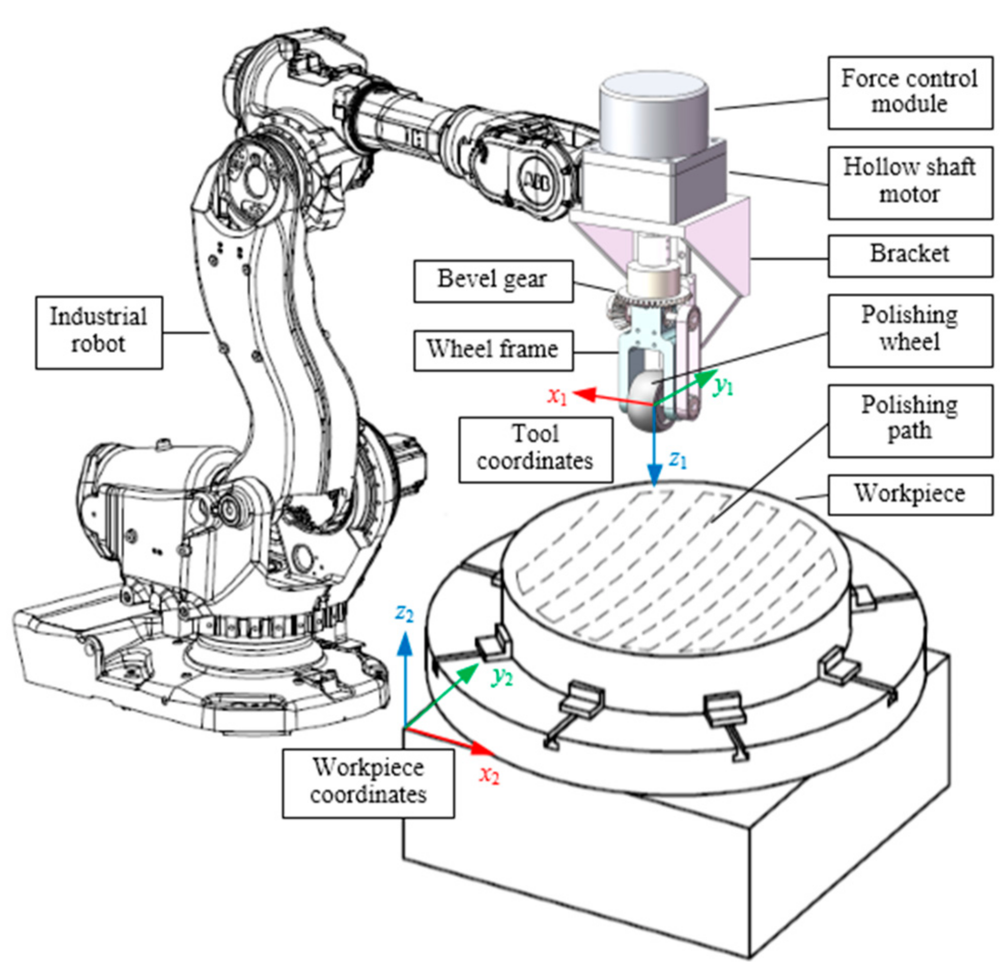
The SWPT is installed on a 6-axis industrial robot to achieve position and attitude control, so that the polishing wheel is always perpendicular to the mirror surface, ensuring the stability of the contact area. The robot drives the SWPT to run according to the set processing path and speed to achieve optical surface forming [
24].
2.1. Structure of the SWPT
The traditional wheel polishing tool controls the polishing pressure with the pressing depth of the flexible polishing wheel [
23]. This method has high requirements on the motion accuracy of the motion actuator, and the motion accuracy of the industrial robot is sub-millimeter level, which obviously cannot meet the motion accuracy requirements. Therefore, we control the polishing pressure by adopting a pneumatic floating structure, which can reduce the requirements for motion accuracy.
The structure of the SWPT is shown in
Figure 1. It is mainly composed of a force control module, a hollow shaft motor, a bracket, a bevel drive, a belt drive, a wheel frame, and a polishing wheel. The main body of the force control module is a low-friction cylinder. The closed-loop control makes the polishing pressure control accuracy reach 1 N. The shaft of the motor is hollow, and the motor does not move up and down. It transmits the rotary motion to the large bevel gear, the small bevel gear changes the rotation direction, and the polishing wheel is rotated by the pulley. The beneficial effects of the structure are: (1) the motor does not move, the motion inertia is small, and the force control precision is high; and (2) the pneumatic floating mode reduces the requirements of motion accuracy.
2.2. Structure of the Polishing Wheel
The polishing wheel is the most important part of the SWPT, because it is in contact with the workpiece and directly determines the fabrication effect. The traditional polishing wheel has a three-layer structure: an internal rigid hub, a flexible rubber in the middle, and an external polishing pad. The TIF of this type of polishing wheel is an asymmetric shape with a central depression, when the polishing pressure is greater than a certain value. Therefore, we have designed an innovative polishing wheel, as shown in the
Figure 2. The polishing wheel has a two-layer structure: an internal rigid hub and an external flexible polishing pad. The rigid hub adopts the spherical profile of aluminum alloy material. The flexible layer uses a polyurethane polishing pad, which can ensure a good fit between the polishing wheel and the workpiece, and achieve a high material removal rate and good surface quality. The flexible polishing pad is glued to the rigid hub. In order to make the polishing wheel capable of medium and high frequency dressing, the size of the polishing wheel should be as small as possible. At the same time, in order to take into account the processing efficiency, we designed a polishing wheel with a spherical side surface, a sphere diameter of 50 mm, a hub width of 20 mm, and a flexible layer thickness of 2 mm. In order to clearly show the structure of the polishing wheel,
Figure 2 is a cross-sectional view of the polishing wheel.
3. TIF of the SWPT
3.1. Preston Equation
The optical polishing process is very complicated. During the polishing process, not only does the mechanical cutting action exist between the tool and the workpiece surface, but also the chemical action between the polishing liquid and the workpiece surface, and there is also a molecular flow phenomenon on the workpiece surface. It is very difficult to establish a mathematical relationship between the material removal rate and all parameters. After simplification, Preston established a linear relationship between material removal rate, polishing pressure, and polishing speed [
25], which is:
where
is the material removal rate,
K is the Preston coefficient, which indicates the polishing efficiency,
P is the contact pressure, and
V is the relative velocity between the tool and the workpiece. When the relative velocity and the contact pressure are known, the amount of material
removed in time
can be calculated.
3.2. Modeling Pressure Distribution
According to the Hertz contact theory, a spherical elastic body in contact with a planar rigid body will produce a circular contact area, and the contact pressure distribution will be Gaussian with a central peak [
26]. However, the polishing wheel also rotates when contacting the workpiece, which causes sliding friction and affects the shape and pressure distribution of the contact area. The flexible layer of the polishing wheel is very thin, which does not meet the conditions of the Hertz contact theory. Therefore, the Hertz contact theory cannot accurately predict the contact area shape and pressure distribution during polishing. So, we use the finite element method to study the contact state.
The contact model between the polishing wheel and the workpiece is shown in
Figure 3. When the polishing wheel is not rotating, the contact area is circular (
Figure 3b, black dotted line). When the polishing wheel is rotating, friction resistance is generated, which causes the screwed-in part of the flexible polishing pad to be squeezed and the contact area to become larger, the screwed-out part of the flexible polishing pad is stretched and the contact area becomes smaller, and eventually the contact area becomes oval (
Figure 3b red solid line).
This paper uses the finite element method to study the dynamic contact characteristics between the polishing wheel and the workpiece. The finite element model consists of a polishing wheel and a workpiece. The polishing wheel consists of an external flexible polishing pad and an internal rigid hub. The flexible layer uses a polyurethane polishing pad with a thickness of 2 mm. The rigid hub is a spherical wheel with a diameter of 50 mm and a width of 20 mm, and the material is aluminum alloy. The workpiece is K9 glass with length, width and height of 80 mm, 30 mm and 15 mm, respectively.
The 3D model is imported into the ABAQUS finite element software, and its element type is a 8-node 6-hedron, as shown in
Figure 4. The material parameters of the model components are shown in
Table 1. Among them, a rectangular coordinate system is established with the contact center point of the polishing wheel and the workpiece as the origin, and the center point Rp of the rigid hub rotation axis is used as the control reference point.
Contact constraint: Establish a contact constraint between the flexible polishing pad and the workpiece and set the friction coefficient to 0.4.
Boundary condition: The workpiece’s six degrees of freedom are completely limited, and the rigid hub has only one degree of freedom for rotation and one degree of freedom for movement of the vertical workpiece surface. A coupling constraint is established between the inner surface of the flexible polishing pad and the outer surface of the rigid hub.
Load: A pressure load of 20 N and a motion load of 2 rps are applied to the central control point Rp.
After calculation by the ABAQUS software, the pressure distribution is obtained, as shown in
Figure 5. It can be seen from the pressure distribution that the contact area is oval, symmetrical up and down, and asymmetrical left and right. This is because when the polishing wheel rotates, friction resistance is generated, which causes the screwed-in part of the flexible polishing pad to be squeezed and the contact area becomes larger, the screwed-out part of the flexible polishing pad is stretched, and the contact area becomes smaller. The point of maximum pressure is the origin of the coordinate system, because this point has the largest deformation.
3.3. Modeling TIF
Because the flexible polishing pad is very thin, the pressing depth is very small, and the size of the contact area is much smaller than the size of the polishing wheel. Therefore, it can be approximated that the linear velocity of each point in the contact area is the same, i.e., V = wR, where V is the linear velocity of each point in the contact area, w is the angular velocity of the polishing wheel, and R is the radius of the polishing wheel.
Since the linear velocity is approximately the same, Equation (2) can be simplified to:
Therefore, the TIF has a linear relationship with the pressure distribution, and their shapes are consistent.
3.4. Experiment of TIF
Experimental steps: (1) Select a piece of glass with good flatness, mark the direction of the glass and detect its initial form with an interferometer. (2) Perform a material removal experiment, then align the first detection position and measure the experimental form. (3) Subtract the two forms to obtain the removal amount and calculate the TIF according to the experimental time. The experimental parameters are shown in
Table 2.
Experimental results: The experimental TIF is shown in
Figure 6. The shape is oval, 4 mm in FWHM (full width at half maximum) in x-direction, 3.5 mm in FWHM in y-direction. The SWPT has a very high processing efficiency: with a peak removal rate of 115 nm/s and a volume removal rate of 0.15 mm
3/min.
Figure 7 normalizes the theoretical and experimental TIF. It can be seen from
Figure 7 that the theoretical results are in good agreement with the experimental results, which proves the correctness of the theoretical model. Here the cosine similarity formula is used to calculate the similarity of the experimental and theoretical TIFs to the Gaussian form. The cosine similarity formula is:
where TIF
1 is a theoretical or experimental TIF, and TIF
2 is a Gaussian-shaped TIF.
The calculation results show that the similarity between the theoretical TIF and the Gaussian TIF in the x-direction reaches 95.6%, and the similarity in the y-direction reaches 74.8%. The similarity between the experimental TIF and the Gaussian TIF in the x-direction reaches 94.8%, and the similarity in the y-direction reaches 74.3%. The low similarity of TIF in the y-direction is due to the influence of frictional resistance.
4. Application in High-Precision Optical Fabrication
The processing steps are as follows: (1) Select a piece of flat glass with poor flatness, mark the direction of the glass and detect its initial surface form with an interferometer; (2) calculate the dwell time using the iterative deconvolution method based on the surface form and the TIF without considering edge effects; (3) calculate the running speed of the robot according to the processing path and dwell time, and perform processing and detection; (4) if the surface form meets the requirements, complete the processing, and if it does not meet the requirements, proceed to the next round of processing. The processing parameters are shown in
Table 3, and the processing device is shown in
Figure 8.
The processing results are as follows: the form error maps after processing are shown in
Figure 9, and the convergence curves of the form error are shown in
Figure 10. In the first processing of 95 min, the form error converged to PV-0.857λ, RMS-0.129λ, and PV and RMS converged by 40% and 58%, respectively. In the second processing of 64 min, the form error converged to PV-0.256λ, RMS-0.049λ, and PV and RMS converged by 70% and 62%, respectively. In the third processing of 18 min, the form error converged to PV-0.173λ, RMS-0.013λ, PV and RMS converged by 32% and 73%, respectively. In the fourth processing of 9 min, the form error converged to PV-0.144λ, RMS-0.009λ, PV and RMS converged by 17% and 31%, respectively. After 4 times of processing for about 3 h, PV and RMS have converged by 90% and 97%, respectively. The form accuracy achieved the expected target of RMS-0.02λ, which proves that the SWPT has the characteristics of high convergence rate and high fabrication accuracy. The SWPT has a broad application prospect in the field of high-precision optical fabrication.
5. Discussion
In the present study, we investigated the TIF of the SWPT, and its application in high-precision optical fabrication. By designing an innovative two-layer polishing wheel, we obtained a stable Gaussian-like TIF. Using the SWPT, we produced a high-precision surface form in a short time. To our knowledge, this is the first time a wheel polishing tool has been used to produce such a high-precision surface form. This result is significant because it shows that the SWPT is expected to become a new generation of efficient and high-precision optical fabrication technology.
The traditional polishing wheel has a three-layer structure: an internal rigid hub, a flexible rubber in the middle, and an external polishing pad [
20,
21,
22]. The TIF of this type of polishing wheel is an asymmetric shape with a central depression, when the polishing pressure is greater than a certain value [
15], and which will cause mid-to-high frequency form errors. The two-layer polishing wheel we designed can always keep the TIF as a Gaussian-like shape, regardless of the polishing pressure, because the deformation of the flexible layer is also Gaussian. Due to the influence of friction resistance, the instantaneous TIF of the polishing wheel is non-rotationally symmetric, and the deepest part is not the center of revolution but is eccentric. When the polishing wheel is in rotation and revolution motions, the integrated TIF takes on a good Gaussian shape. However, when the revolution motion is accompanied by linear motion, the processing results will be wavy, which will cause mid-to-high frequency form errors. We discarded the revolution of the polishing wheel to keep the TIF consistent. Therefore, we produced a very high-precision surface form in a short time. However, because the polishing wheel only rotates, it will produce a polished texture in a single direction, resulting in poor roughness. This will be the subject of our future research.
6. Conclusions
In this paper, we built a new and patented polishing tool called the Self-rotating Wheel Polishing Tool (SWPT). The polishing wheel is an innovative two-layer structure: a rigid hub inside and a flexible polishing pad outside. Compared with the traditional three-layer structure polishing wheel, the TIF of this structure is more stable.
By using the finite element analysis method, the dynamic contact characteristics between the polishing wheel and the workpiece were studied, and the theoretical TIF was modeled. The TIF was not circular, but oval. This is because when the polishing wheel rotates, friction resistance is generated, which causes the screwed-in part of the flexible polishing pad to be squeezed and the contact area to become larger. The screwed-out part of the flexible polishing pad is then stretched, and the contact area becomes smaller. Then, we ran material removal experiment, and it was found that the experimental TIF and the theoretical TIF are very close, and both are close to the Gaussian shape, thus verifying the correctness of the contact finite element model.
Finally, optical fabrication was performed. After four times of about 3 h processing, the form error converged from PV-1.434λ, RMS-0.308λ to PV-0.144λ, RMS-0.009λ, and PV and RMS converged by 90% and 97%, respectively. The form accuracy achieved the expected target of RMS-0.02λ, which proves that the SWPT has the characteristics of high convergence rate and high fabrication accuracy. The SWPT has a broad application prospect in the field of high-precision optical fabrication.
Author Contributions
Conceptualization, Y.Y., Z.M., and X.F.; methodology, Y.Y. and Q.L.; formal analysis, J.D.; investigation, Y.Y.; data curation, Y.Y. and Y.W.; writing—original draft preparation, Y.Y. and Q.L.; writing—review and editing, Y.W.; supervision, Z.M. and X.F.; project administration, Y.Y.; funding acquisition, Y.Y. All authors have read and agreed to the published version of the manuscript.
Funding
This research was funded by the Shaanxi Province Key R&D Program (Project No. 2020GY-157), the Youth Innovation Promotion Association CAS.
Institutional Review Board Statement
Not applicable.
Informed Consent Statement
Not applicable.
Data Availability Statement
The data presented in this study are available on request from the corresponding author.
Acknowledgments
We are very grateful for Le-Shen’s help in optical inspection.
Conflicts of Interest
The authors declare no conflict of interest.
References
- Rao, Z.; Guo, B.; Zhao, Q. Investigation of contact pressure and influence function model for soft wheel polishing. Appl. Opt. 2015, 54, 8091–8099. [Google Scholar] [CrossRef] [PubMed]
- Yuan, J.; Wu, Z.; Lu, B.; Nguyen, D.; Lu, H.; Zhao, P. Review on Ultra-precision Polishing Technology of Aspheric Surface. Chin. J. Mech. Eng. 2012, 48, 167–177. [Google Scholar] [CrossRef]
- Peng, W.; Guan, C.; Li, S. Efficient fabrication of ultrasmooth and defect-free quartz glass surface by hydrodynamic effect polishing combined with ion beam figuring. Opt. Express 2014, 22, 13951–13961. [Google Scholar] [CrossRef] [PubMed]
- Jones, R.A. Computer-controlled optical surfacing with orbital tool motion. Opt. Eng. 1986, 25, 780–790. [Google Scholar] [CrossRef]
- Kim, D.; Park, W.; Kim, S.; Burge, J. Parametric modeling of edge effects for polishing tool influence functions. Opt. Express 2009, 17, 5656–5665. [Google Scholar] [PubMed]
- Yao, Y.; Ma, Z.; Xu, L.; Ding, J.; Wang, Y.; Shen, L.; Jiang, B. Removal functions of different polishing heads worked in planet motion model. Opt. Precis. Eng. 2017, 25, 2706–2713. [Google Scholar]
- Martin, H.; Anderson, D.; Angel, J.; Nagel, R.; West, S.; Young, R. Progress in the stressed-lap polishing of a 1.8 m f/1 mirror. Proc. SPIE 1990, 1236, 682–690. [Google Scholar]
- West, S.; Martin, H.; Nagel, R.; Young, R.; Davison, W.; Trebisky, T.; Derigne, S.; Hille, B. Practical design and performance of the stressed-lap polishing tool. Appl. Opt. 1994, 33, 8094–8100. [Google Scholar] [CrossRef] [PubMed]
- Golini, D.; Kordonski, W.; Dumas, P.; Hogan, S. Magnetorheological finishing (MRF) in commercial precision optics manufacturing. Proc. SPIE 1999, 3782, 80–91. [Google Scholar]
- Su, J.; Cheng, H.; Feng, Y.; Tam, H. Study of a wheel-like electrorheological finishing tool and its applications to small parts. Appl. Opt. 2016, 55, 638–645. [Google Scholar] [CrossRef]
- Ren, K.; Luo, X.; Zheng, L.; Bai, Y.; Li, L.; Hu, H.; Zhang, X. Belt-MRF for large aperture mirrors. Opt. Express 2014, 22, 19262–19276. [Google Scholar] [CrossRef] [PubMed]
- Walker, D.; Brooks, D.; King, A.; Freeman, R.; Morton, R.; McCavana, G.; Kim, S. The ‘Precessions’ tooling for polishing and figuring flat, spherical and aspheric surfaces. Opt. Express 2003, 11, 958–964. [Google Scholar] [CrossRef] [PubMed]
- Cao, Z.; Cheung, C.; Liu, M. Model-based self-optimization method for form correction in the computer controlled bonnet polishing of optical freeform surfaces. Opt. Express 2018, 26, 2065–2078. [Google Scholar] [CrossRef] [PubMed]
- Zhong, B.; Wang, C.; Chen, X.; Wang, J. Time-varying tool influence function model of bonnet polishing for aspheric surfaces. Appl. Opt. 2019, 58, 1101–1109. [Google Scholar] [CrossRef] [PubMed]
- Shi, C.; Peng, Y.; Hou, L.; Wang, Z.; Guo, Y. Improved analysis model for material removal mechanisms of bonnet polishing incorporating the pad wear effect. Appl. Opt. 2018, 57, 7172–7186. [Google Scholar] [CrossRef] [PubMed]
- Ke, X.; Qiu, L.; Wang, C.; Wang, Z. Tentative Investigations on Reducing the Edge Effects in Pre-Polishing the Optics. Appl. Sci. 2020, 10, 5286. [Google Scholar] [CrossRef]
- Cao, Z.; Chi, F.; Xing, Z. A theoretical and experimental investigation of material removal characteristics and surface generation in bonnet polishing. Wear 2016, 360, 137–146. [Google Scholar] [CrossRef]
- Drueding, T.; Bifano, T.; Fawcett, S. Contouring algorithm for ion figuring. Precis. Eng. 1995, 17, 10–21. [Google Scholar] [CrossRef]
- Liao, W.; Dai, Y.; Xie, X.; Zhou, L. Microscopic morphology evolution during ion beam smoothing of Zerodur® surface. Opt. Express 2014, 22, 377–386. [Google Scholar] [CrossRef] [PubMed]
- Han, Y.; Zhang, L.; Fan, C.; Zhu, W.; Beaucamp, A. Theoretical study of path adaptability based on surface form error distribution in fluid jet polishing. Appl. Sci. 2018, 8, 1814. [Google Scholar] [CrossRef] [Green Version]
- Pfaff, M. High speed fabrication of aspheres and optical freeform surfaces. In Proceedings of the Frontiers in Optics 2008/Laser Science XXIV/Plasmonics and Metamaterials/Optical Fabrication and Testing, New York, NY, USA, 21–24 October 2008; p. OThD6. [Google Scholar]
- Opto Tech. Advanced Wheel Polishing Tool. 2017. Available online: http://www.optptech.de/en/advanced-wheel-polishing-tool-awpt (accessed on 30 November 2021).
- Seo, H.; Han, J.; Kim, S.; Seong, S.; Yoon, S.; Lee, K.; Hong, J.; Lee, H.; Bok, M. Novel orthogonal velocity polishing tool and its material removal characteristics from CVD SiC mirror surfaces. Opt. Express 2016, 24, 12349–12366. [Google Scholar] [CrossRef] [PubMed]
- Yao, Y.; Ma, Z.; Ding, J.; Chen, Q.; Fan, X.; Shen, L.; Li, Q. Heavy-calibre off-axis aspheric surface polishing by industrial robot. Proc. SPIE 2019, 10838, 1083803. [Google Scholar]
- Preston, F.W. The theory and design of plate glass polishing machines. J. Soc. Glass Technol. 1927, 11, 214–256. [Google Scholar]
- Bouvier, C.; Gracewski, S.; Burns, S. Contact mechanics models and algorithms for dome polishing with ultraform finishing. Proc. SPIE 2007, 6545, 65450R. [Google Scholar]
| Publisher’s Note: MDPI stays neutral with regard to jurisdictional claims in published maps and institutional affiliations. |
© 2022 by the authors. Licensee MDPI, Basel, Switzerland. This article is an open access article distributed under the terms and conditions of the Creative Commons Attribution (CC BY) license (https://creativecommons.org/licenses/by/4.0/).


