Abstract
The hydrogen compression that occurs in a metal hydride compressor is based on the chemical and thermal processes of hydrogen absorption and desorption into an intermetallic structure of metals. The concept presented in this article is centred on the use of an optimal metal alloy that is capable of absorbing hydrogen into its structure at a low temperature and pressure. After such an alloy is heated up, its pressure will significantly increase, and this facilitates the compression of hydrogen without it being in direct contact with the movable parts of the compressor. As a result, the safety of the compression process is increased. The hydrogen compressor contains a pair of tandem metal hydride (MH) tanks with an integrated heat exchanger. The tanks are alternately heated and cooled, so that while hydrogen is absorbed in one of the tanks it is concurrently desorbed in the other tank. The unique nature of the prototype single-stage metal hydride compressor consists in using a heat pump that facilitated a significant reduction of the consumed electric energy in the heat transport between the tandem-arranged tanks. The purpose of this investigation was to examine the possibility of integrating a heat pump as a source of heat and cold for the process of absorption- and desorption-based hydrogen compression. With the prototype MH compressor presented in this article, a compression ratio of ε = 2.0 was achieved while the tanks were operated at temperatures ranging from 12 to 55 °C. In a single cycle, the compressor worked with 166 litres of hydrogen, which was absorbed into 3.125 kg of the La0.85Ce0.15Ni5 alloy. The average heating power that was achieved on the side of the condenser that heated the MH1 tank was 362 W, and the cooling power that was achieved on the evaporator side was 300 W. The achieved value of the heat pump COP was 2.92.
1. Introduction
Typically, hydrogen is not found in nature in an unbound molecular form. It is most frequently produced by partial oxidation of natural gas, steam reforming, or electrolysis of water [1,2,3]. Any hydrogen that is not used immediately after it is produced must be stored [4,5,6,7]. However, due to the low density of hydrogen, most storage methods require the use of a compressor to increase the hydrogen pressure to the required level. At high flow rates, the compression of hydrogen may be achieved by using a turbo- or reciprocating compressor. At low flow rates, it is possible to use a pneumatic pressure booster, which is also based on the reciprocating compression [8,9,10].
In the cases mentioned above, the energy demand for the compression process is very high [11]. The amount of the energy used in the compression reduces the overall transformation efficiency and thereby increases the cost of the fuel [12].
One of the possible means of hydrogen compression is the use of reversible hydrogen storage in metal alloys, while applying a method based on thermal changes [13]. This technology was also discussed in paper [14], which pointed out a continuous growth of the R&D activities in the development of the metal hydride hydrogen compression technology. A compressor works in an enclosed thermodynamic cycle, in which the hydrogen is stored at a low temperature due to the catalytic effects of metals [15]. This is followed by dissociation of the hydrogen molecules and diffusion of the atoms into an intermetallic structure of the alloy. Once the alloy has been saturated with hydrogen, it is necessary to supply heat from an external source, which increases the pressure as the operating point shifts to a higher isothermal curve. At a higher temperature, it is then possible to desorb hydrogen from the alloy and reduce the storage capacity to the baseline value. Once the temperature has been decreased, the baseline operating point will be restored.
The principle of hydrogen compression through the absorption into a metal hydride has been known for more than 40 years. Many scientific teams have been working on developing metal hydride compressors that are suitable for real operations [16,17]. The importance of this issue is also demonstrated by numerous studies that have been carried out in the field of hydrogen storage and compression globally over the last years.
A three-stage metal-hydride-based hydrogen compressor (MHHC) has been designed for the equipment intended for hydrogen production using a low-pressure alkaline electrolyser, in which the compression system performs hydrogen desorption using the heat obtained from an electrolyser. This type of compressor achieved a compression ratio of 2/0.1 MPa while working with three different metal hydrides of the AB5 type at temperatures ranging from 20 to 80 °C [18].
The American Laboratory of Chemical Sciences and Material Systems carried out the investigation into thermodynamics and kinetics of a prototype Metal Hydride Hydrogen Compressor (MHHC). During their tests, the compressor worked without any problems while compressing 320 g of hydrogen. However, this solution may only become an alternative to mechanical or electrolytic compression if the process is fully automated and the waste heat is utilized [19].
The team led by Karagiorgis developed a six-stage metal hydride compressor (MHC) that was able to compress hydrogen while shifting the pressure value from 7 bar to over 220 bar. This MHC exhibited a stable operation at temperatures ranging from 10 to 80 °C. The specific productivity of the metal hydride compressor achieved as much as 67.2 LH2·kg−1·h−1 [20].
Deployment of a metal hydride compressor in a real operation was analysed in paper [21,22]. Paper [21] provided an assessment of the technological and energy aspects related to the potential integration of a metal hydride compressor in the existing energy systems. The advantages of this technology include simple production, absence of moving parts, safety and reliability, and a possibility to use the waste industrial heat and/or excess renewable energy. The analysis provided by this study clearly shows that a hydrogen compressor containing metal hydride has a good potential to be commercialised, provided that certain measures are implemented with the aim of shifting the power engineering industry away from using fossil fuels and increasing the proportion of renewable sources on the market.
Designs of metal hydride compressors often depend on analytical and numerical calculations, and with a sufficient database of experimental data from real-life applications it is possible to create models for predicting the operating parameters of single- and multi-stage MHCs. Such a model was created by the team led by Mr. Lototskyy. The model facilitates predicting the cycle productivities of the MH materials in compressors, throughput productivity of the hydrogen compressor, H2 pressures in between the stages for multi-stage layouts, and specific heat consumption for the H2 compression. Authors of the model reported a satisfactory concordance between the predicted results and the real values obtained by experiments, with a deviation of less than 18%. The developed model was proposed as a useful tool in the development of a metal hydride hydrogen compressor via optimising the properties of the metal hydride materials for hydrogen compression and their relative amounts at each particular stage [23,24].
The key challenge in designing metal hydride compressors is the reduction of energy demand of hydrogen compression by discovering a cheap source of cold and heat. One of the promising visions is the use of highly efficient thermodynamic cycles of heat pumps, which significantly save the consumed energy when compared to the conventional sources. It is therefore necessary to use a heat pump with a high COP (Coefficient of Performance) when defining the range of operating temperatures of the used MH materials.
In the present article, the prototype design is presented for a tandem hydrogen compressor with a metal hydride alloy and a heat pump, which is intended for the compression of hydrogen of higher purities, produced primarily in electrolysers. The use of the heat pump increases the efficiency of heat transport between the tanks that are arranged in series. Moreover, the use of a thermal cycle in which the hydrogen is not in contact with the movable parts of the compressor results in a high safety standard [25].
2. Description of the Designed MH Compressor Mechanism
The underlying principle of hydrogen compression is its absorption into the La0.85Ce0.15Ni5 metal alloy; Figure 1 shows two of the alloy’s PCI characteristics at various temperatures and a plotted thermal cycle. The absorption process is characterized between points A and B. The absorption ran at a temperature of 10 °C and the heat was removed from the tank using a heat pump evaporator. After the absorption was completed, the alloy was heated to a temperature of min. 50 °C, which significantly increased the pressure. Subsequently, the hydrogen was desorbed at a temperature of 50 °C, but at a significantly higher pressure (between points C and D).
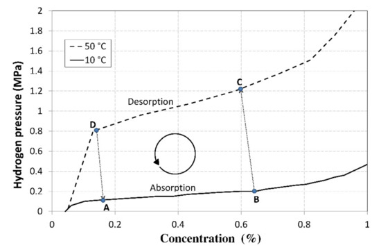
Figure 1.
PCI characteristics of the La0.85Ce0.15Ni5 alloy with a plotted operating cycle of the compressor.
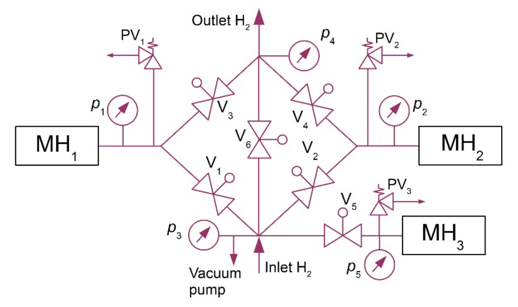
After the hydrogen desorption at higher pressures, the alloy was refrigerated back to the baseline temperature of 10 °C. In order to maintain the continuous operation of the compressor, two MH tanks were arranged in series and the heat was transported between them using a heat pump. The hydrogen absorption in the MH1 tank and the hydrogen desorption from the MH2 tank ran simultaneously (Figure 2). However, during the intervals when the temperature was changing, between points BC and DA, the hydrogen absorption did not take place in any of the tanks; that is why an additional tank was used (MH3) together with a compressor to absorb hydrogen while the operating temperatures of MH1 and MH2 tanks were changing. This facilitated a continuous hydrogen flow at the inlet into the compressor.
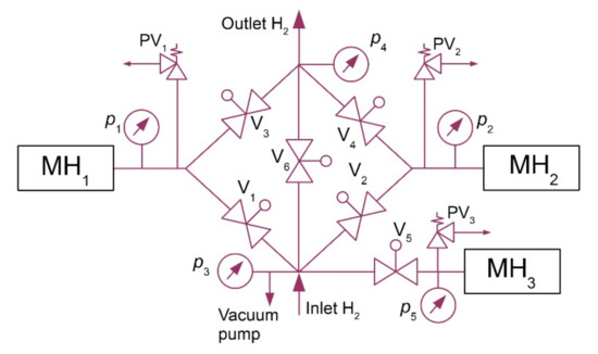
Figure 2.
Hydrogen circuit diagram.
This additional tank had a separated thermal management, which was based on a pair of (PT) TEC1-12708 Peltier modules with a cooling power of 63 W at a zero-temperature difference between its hot and cold sides. Peltier modules facilitate switching between the heating and cooling modes by simply reversing polarity of the power supply. They may be used to regulate the temperature within the range from 0 to 70 °C. The purpose of such a design, which was used at the operating temperatures of 10–50 °C, was to approximate, as much as possible, the ideal compression ratio ε = 4. The expected mean COP of the heat pump was 3; this means that 1/3 of the electric energy was expected to be used for the compression compared to the thermal energy produced in the heat pump condenser. This significantly reduced the consumption of electric energy during hydrogen compression. In one cycle, the compressor used 0.166 m3 of hydrogen in one MH tank. Figure 2 shows the basic diagram of the hydrogen circuit of the metal hydride compressor. It contained the electrically controlled JAKSA Magnetni Ventili hydrogen valves (0–150 bar; 290,100 TMEx35/D), Parker HPRVSM6A-V-K2-435 safety valves, and pressure sensors with analogue output signal, BD SENSORS 110-4002-E-1-100-N40-1-111 type.
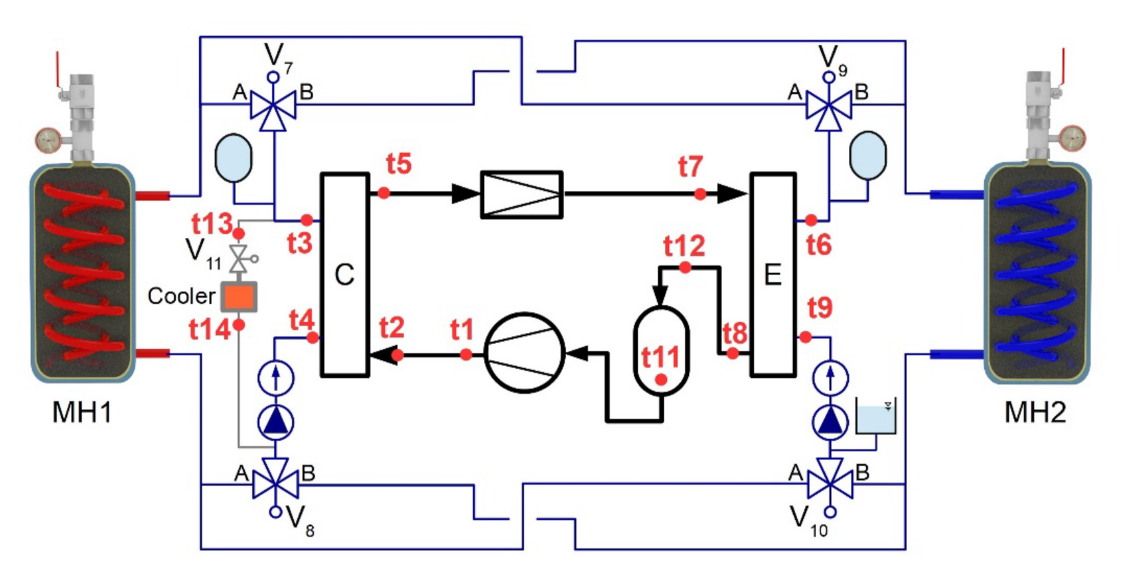
A maximum heating power of the heat pump was 1.2 kW and the maximum cooling power was 1 kW. Electronically controlled 3-way zone valves were used to change the direction of the heat-transfer fluid stream from the condenser to the MH1 or MH2 tanks (Figure 3). This facilitated a cyclical change in the temperatures of both tanks, as was required by the designed control algorithm. In order to ensure the removal of excess heat, produced as a result of a higher heating power on the condenser side than the cooling power on the evaporator side, this circuit was equipped with an auxiliary cooler “C”.

Figure 3.
Diagram of a heat pump with a water circuit.
This prototype MH compressor with the heat pump was designed with an autonomous control system. For this purpose, a Raspberry Pi control minicomputer with additional cards (1-wire; A/D converter-16 bit; I/O ports—32×) was integrated with the Linux distribution Raspbian operating system. The control software was written in C++ language in Qt Creator environment. The compressor contained a touch screen for the control and visualization of the measured data.
The compressor prototype was designed with independent modules in order to facilitate future applications within the research into the optimization of MH compressors, where component replacements and design optimization might be required. The control PC was connected to 36 temperature sensors BD18B20 with accuracy of ±0.5 °C, which facilitated the monitoring of thermal fields of the individual components. The heat pump with a water circuit contained 14 temperatures sensors (t1 through t14), which facilitated analysing the condition and transient performance of the compressor during operation.
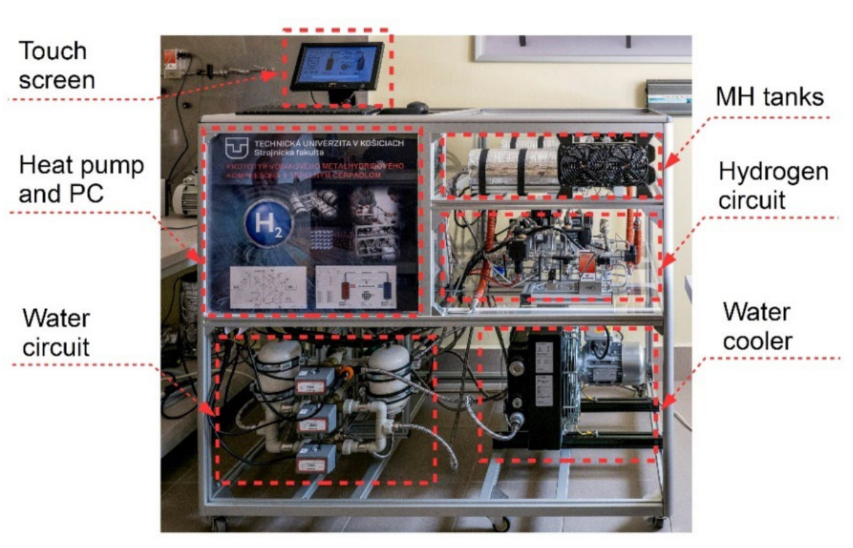
The measurement system also included 7 pressure sensors (5 sensors for H2 and 2 sensors for a coolant in the heat pump) with accuracy of 0.4% and 5 flow meters with accuracy of 1% (2 hydrogen mass flow rate meters and 3 heat-transfer fluid flow meters). At the outlets from I/O ports, there were 27 relays that facilitated controlling all the compressor devices (electronic valves, devices, coolers, etc.). Figure 4 shows the final arrangement of the components and Table 1 contains a description of the basic parameters of the MH compressor.

Figure 4.
MH compressor with a heat pump.

Table 1.
Description of the basic parameters of the MH compressor.
Each of the used tandem-arranged MH tanks contained 3.125 kg of the alloy and an internal tubular heat exchanger, through which the heat-transfer fluid flew from the condenser or the evaporator of the heat pump.
Description of the Compressor’s Thermal Cycle
Figure 1 shows the basic thermal cycle of the compressor that used the La0.85Ce0.15Ni5 alloy, which is capable of forming metal hydrides. The cycle was plotted using the measured PCIs (Pressure-Concentration Isotherms) at the temperatures ranging from 10 to 50 °C. The baseline point A represents the baseline alloy status, in which the concentration of the absorbed hydrogen was 0.16% at a pressure of 0.12 MPa. In the zone between points A and B, hydrogen was absorbed into the alloy while the heat was released. The amount of the released heat of reaction, specific for the La0.85Ce0.15Ni5 alloy, was identified by an experimental measurement and amounted to 1 MJ·m−3 of H2. After the alloy was saturated to a concentration of 0.66%, the pressure increased to 0.2 MPa. Due to an increasing pressure gradient, a further increase in the concentration would be unreasonable as it would lead to a reduced compression ratio and an unnecessary increase in the operating pressure of the compressor (point C). The heat necessary for maintaining the isothermal conditions is defined as follows:
A » B
After the required concentration was achieved, it was necessary to increase the alloy temperature by adding the heat. It may be divided into the calorimetric heat, the heat necessary to cover the hydrogen desorption, and the effects of the heat loss:
B » C
where in Σ(mi·ci) is the overall heat capacity of the MH tank, including the integrated heat exchanger and the absorbed hydrogen (J·K−1); ΔT is the temperature difference between the working isotherms (K); qdes H2 is the heat of reaction in hydrogen desorption (J·m−3); and ΔVdes H2 is the amount of the hydrogen released due to a temperature increase by ΔT (m3). After the heat was supplied (in the zone between points B and C), the temperature increased by 40 °C and the pressure increased to a value of ca 1.22 MPa. As the pressure increased, the desorption was accompanied with a release of a small amount of hydrogen which increased the pressure of gaseous hydrogen that was present among the alloy grains; therefore, the shift of point C towards the zone with a lower concentration depended primarily on the grain size and on the free volume among the alloy grains.
After the pressure was increased by heating the alloy, the hydrogen desorption began in the zone between points C and D. The total amount of the heat to be supplied to the tank for covering the heat of reaction and the heat loss was calculated as follows:
C » D
The concentration could only be reduced to the value of 0.13%, because lower concentrations would result in an abrupt pressure drop. The pressure in point D amounted to 0.8 MPa, so the compression ratio for the hydrogen compression in a thermal cycle was calculated using the following equation:
where pD is the hydrogen pressure in point D (Pa) and pB is the hydrogen pressure in point B (Pa). During the operation of the compressor with a cyclical use of the La0.85Ce0.15Ni5 alloy at temperatures ranging from 10 to 50 °C and with the mass concentrations of 0.16 and 0.66%, the theoretical value of the compression ratio, as measured on the PCI curves, was εk = 4.
In order to restore the baseline temperature and pressure (the values in point A), it was necessary to cool the tank and remove the heat, the quantity of which was calculated as follows:
D » A
where in qabs H2 is the heat of reaction in hydrogen absorption (J·m−3) and ΔVabs H2 is the amount of the absorbed hydrogen at a temperature decrease representing ΔT (m3).
The hydrogen compressor was designed for the compression of 200 litres of hydrogen in a single cycle. In order to identify the optimal amounts of the metal hydride material at the individual tandem stages of the compressor for the predefined volumetric flow rate of the hydrogen, it was necessary to calculate the mass concentration of the hydrogen using the following equation:
The editing of Equation (6) yielded the equation for calculating the amount of the metal hydride material necessary for the compression of the proposed amount of hydrogen in one stage of the compression:
where ∆c is the change in the mass concentration of the stored hydrogen (1); VH2 is the hydrogen volume (m3); ρH2 is the hydrogen density (kg·m−3); mMH is the mass of the metal hydride alloy (kg). Using Equation (7), the amount of the alloy necessary for the compression of 200 litres of hydrogen in one cycle was calculated as ca 3.5 kg.
3. A Thermal Analysis of the MH Tank during the Hydrogen Absorption (A » B)
Equation (1) describes the amount of the heat removed during the isothermal hydrogen absorption into the metal alloy. If the real amount of the removed heat differs from the predefined value, the average temperature of the tank changes. The heating power generated during the hydrogen absorption PG, plus the heating power received from the surrounding environment through the insulation Pins, is removed by the heat exchanger Phe (Figure 5). If a difference between the cooling power of the heat exchanger and the supplied power (PG + Pins) is not zero, the tank temperature changes while respecting the calorimetric equation.
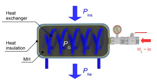
Figure 5.
The MH tank and the thermal balance diagram.
The power balance of the tank for an average temperature of the entire tank t at the time τ is described by the following equation:
The individual powers may be identified using the following equations:
where Qmw is the mass flow rate of the heat-transfer fluid through the heat exchanger (kg·s−1); cw is the heat capacity of the heat-transfer fluid (J·kg−1·K−1); tw-out is the fluid temperature at the outlet from the heat exchanger (°C); and tw-in is the fluid temperature at the inlet to the heat exchanger (°C). This mathematical model was used to calculate the current tank temperatures over time with the known operating parameters. Rewriting Equation (8) from a differential form to a difference form facilitated the calculation of the average difference in the tank temperature Δt with the known time difference Δτ.
The power balance described above was an essential precondition for achieving an optimal design of the MH compressor. Its suitability and accuracy were verified during the measurements of the operating parameters, as described in the next chapter.
4. Measurements of the Operating Parameters of the MH Compressor with a Heat Pump
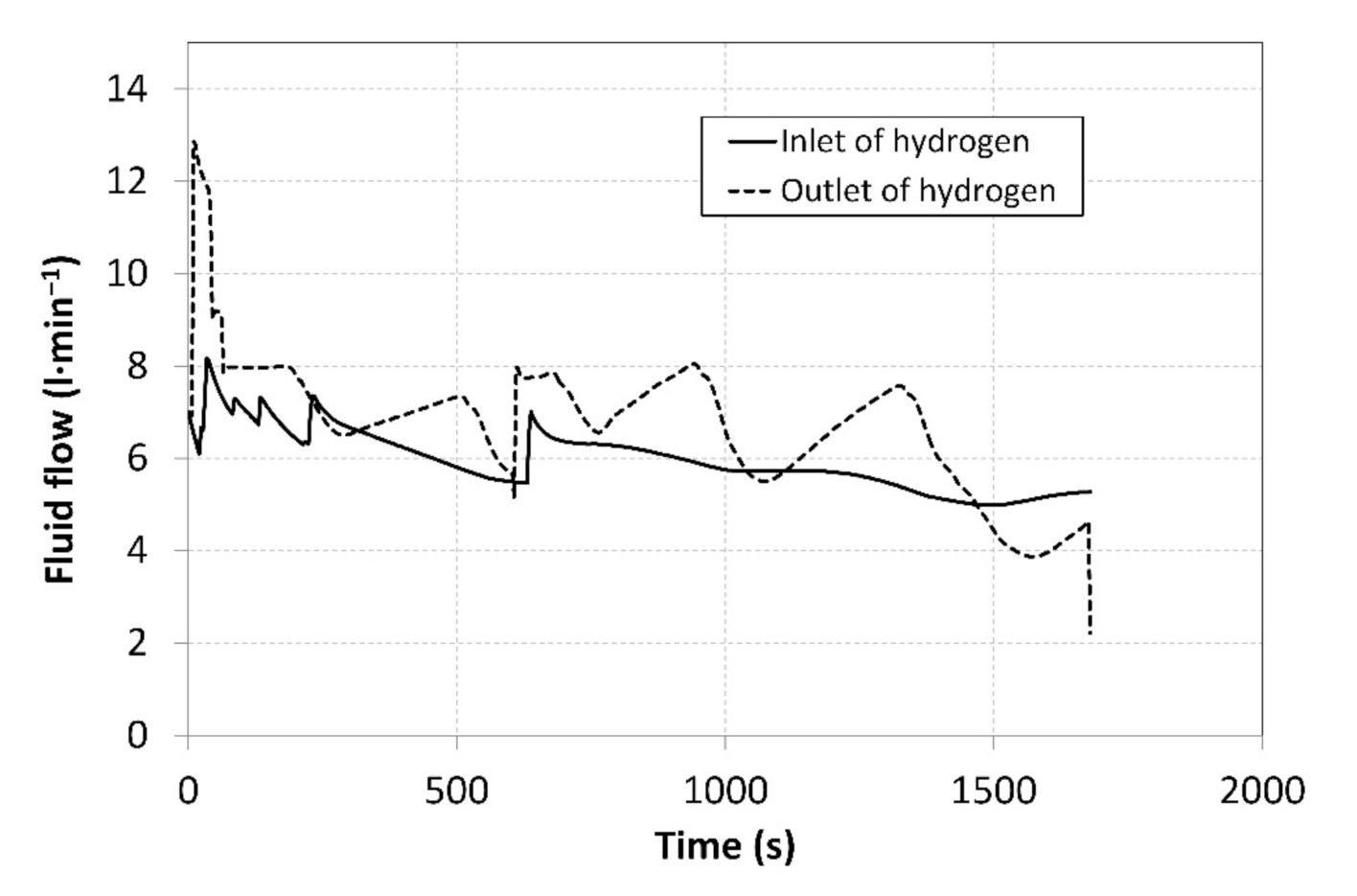
Prior to the measurements, the system was vacuumed with the aim of removing potential undesired gases. This was followed by setting the baseline volumes of hydrogen in individual MH tanks. The MH1 tank was set to the operating point C, as shown in Figure 1, with a baseline hydrogen volume of 280 litres. The MH2 tank was activated in the operating point A, with a baseline hydrogen volume of 80 litres. The MH1 tank was then heated to a temperature of 51 °C to induce the hydrogen desorption at a higher pressure, and the temperature of the MH2 tank was reduced to 10 °C to induce a subsequent hydrogen absorption. By heating the MH1 tank, the operating pressure was stabilized at a value of 1.46 MPa. By cooling the MH2 tank, the pressure was stabilized at a value of 0.3 MPa. After opening the V2 valve, the hydrogen was supplied to the MH2 tank for absorption. Simultaneously, the V3 valve was opened to facilitate hydrogen desorption from the MH1 tank. Figure 6 shows the hydrogen flow rates at the compressor inlet and outlet over the period in which the measurements were carried out. During the measurement, which lasted 1700 s, 487 data were recorded from each sensor installed in the MH compressor; the measured data were therefore plotted as smoothed curves.
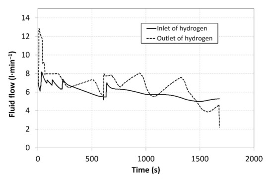
Figure 6.
Curves of the hydrogen flow rates at the compressor inlet and outlet.
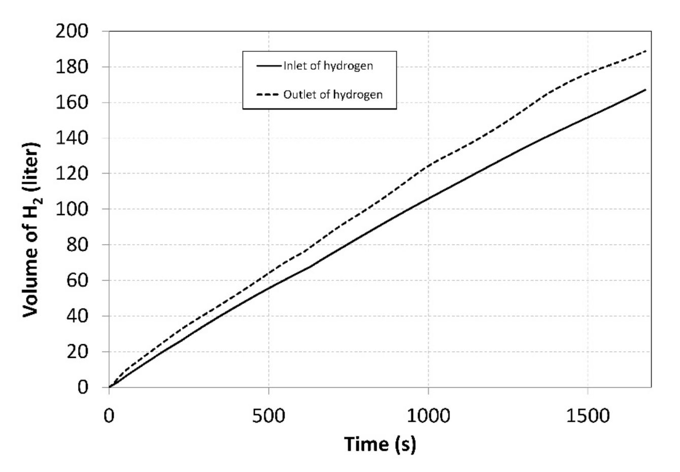
The flow rates were regulated manually using thin dosing valves; that is why the curves exhibit significant degree of dispersion. By integrating the flow rates over time, the total volumes of the hydrogen that flew through the compressor inlet and outlet were identified (Figure 7).

Figure 7.
Total volumes of the hydrogen supplied to/removed from the compressor during measurements.
Over the entire measurement period, 166 litres of hydrogen were supplied into the MH1 tank, while 188 litres were removed from the MH2 tank. This disproportion was caused by the fact that the MH1 tank was heated more intensively, using the heat pump condenser. Identical volumes may be achieved by transferring a larger amount of the heat to an external cooler.
The tank temperatures recorded during the measurements are plotted in Figure 8. The temperature of the MH2 tank could not be maintained at a value of 10 °C during the hydrogen absorption due to a low intensity of the heat removal at higher hydrogen flow rates. The heating power supplied to the MH1 tank was more intensive and facilitated achieving a temperature higher than 50 °C; this contributed to achieving higher compression ratios. In order to avoid extremely high temperatures, the external cooler was activated in short intervals corresponding to the local peaks on the curve with the aim of reducing the temperature of the MH1 tank in short time intervals. The heat-transfer fluid flew from the condenser through the external cooler with a maximum cooling power of 1 kW at the flow rate of 2.5 L·min−1, while the temperatures were measured at the cooler inlet and outlet. The obtained values facilitated calculating the cooler’s power using the calorimetric equation. The average temperature of the surrounding air during the measurement was 22.3 °C. The short intervals when the cooler was in operation are indicated by five vertical dotted lines crossing the curve.
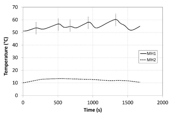
Figure 8.
Curves of the temperatures in the tanks during compression.
Cooling the heat circuit of the heat pump condenser by the auxiliary cooler significantly contributed to maintaining the temperature of the MH2 tank. The reason is that decreasing the temperature in the condenser resulted in a slightly delayed decrease in the temperature of the evaporator that was thermally interconnected with the MH1 tank. Figure 9 shows the curve of hydrogen pressures in the tanks during the measurements.
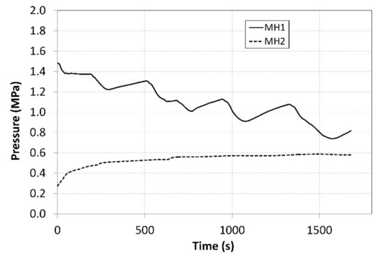
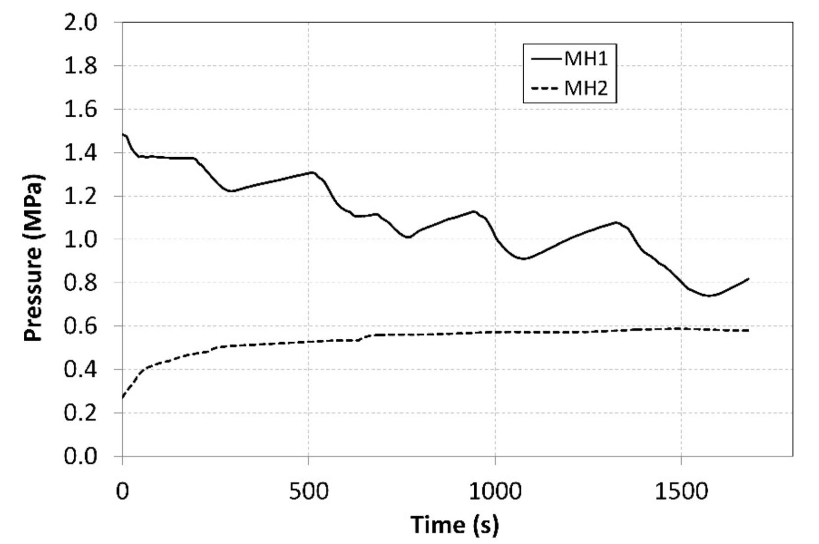
Figure 9.
Curves of relative pressures in MH1 and MH2 tanks.
The pressure in the MH1 tank, from which the hydrogen was desorbed at a higher pressure, significantly depended on its temperature and it exhibited a descending curve as the hydrogen concentration gradually decreased. As the time passed, the pressure in the MH2 tank increased, and its value was much higher than the projected value of 0.2 MPa depicted in Figure 1. Such a development negatively affected the overall trend of the compression ratio. Figure 10 shows the curve of the temperature of the cooling fluid from the heat pump evaporator, which refrigerated the MH2 tank. Analogically, Figure 11 shows the curve of the fluid that heated the MH1 tank.
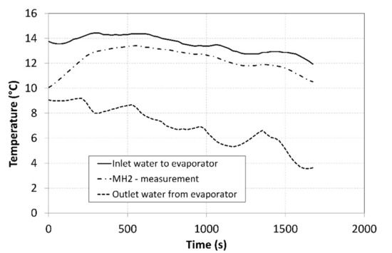
Figure 10.
Thermal management of cooling the MH2 tank.
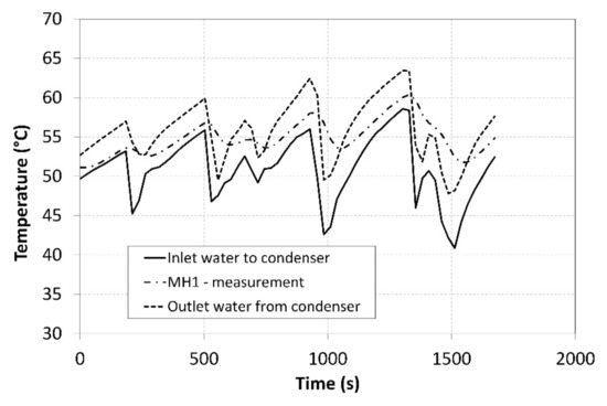
Figure 11.
Thermal management of heating the MH1 tank.
These curves were used to identify the instantaneous heating power and cooling power achieved in the heating and cooling processes while using the calorimetric equation (Figure 12). The volumetric flow rate of the heat-transfer fluid and the temperature difference between the inlet and outlet pipes were measured. The measurement uncertainty for the indirectly identified heating powers significantly depends on a current temperature difference and on the accuracy of the temperature sensor. It may be calculated using the following equation:
where ∂f/∂xj is the partial derivation of the calorimetric equation based on the measured parameter and uBxj is the uncertainty of the sensor measuring the xj parameter. During the measurements, the flow rate of the heat-transfer fluid on the evaporator side amounted to 0.65 L∙min−1, while on the condenser side it was 1.05 L∙min−1. During the measurements, the measurement uncertainty for the heating powers ranged from 16.2 to 19.7%. This was caused by a low value of the measured temperature difference at a relatively high uncertainty of the temperature sensors.
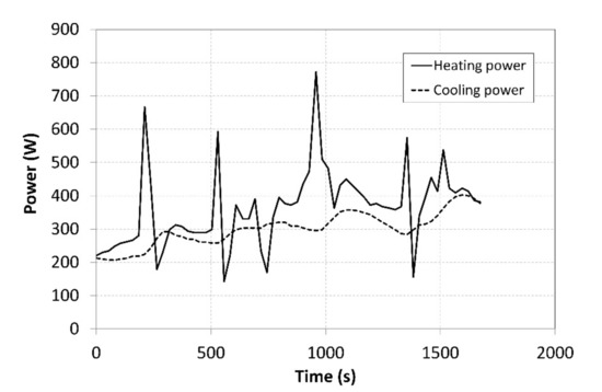
Figure 12.
Cooling and heating powers supplied to the tanks.
The achieved heating powers amounted to approximately 1/3 of the maximum power of the heat pump. Abrupt fluctuations of the heating power on the condenser side were caused by activating the auxiliary cooler. The cooling power curve indicated that there were local increases in the power, which followed, with a slight delay, the changes in the heating power which were caused by the decreasing temperature of the coolant in the heat pump.
5. Analysis of the Results and Discussion
During the measurements, the average hydrogen flow rate at the compressor inlet was 5.96 L·min−1 and the average value of the output flow rate was 6.73 L·min−1 (Figure 6). The hydrogen flow rate was regulated in order to achieve a balanced ratio of the absorption/desorption temperatures in MH1 and MH2 tanks. The heating power supplied from the heat pump condenser was 20.7% higher than the cooling power of the evaporator, and this difference was also manifested by an increase in the total volume of hydrogen at the outlet from the MH compressor. With the aim to ensure the continuous operation, it is necessary to achieve identical volumes of the absorbed and the desorbed hydrogen in the tandem pair of MH tanks; this may only be achieved by the optimal regulation, which will result in identical hydrogen flow rates at the condenser inlet and outlet.
During the measurements, the average temperature of the MH1 tank, in which hydrogen desorption took place, amounted to 54.9 °C (Figure 8). The average temperature of the MH2 tank, in which the hydrogen was absorbed, was 12.3 °C. During the experiment, the absolute temperature shifted to the levels above the designed value; however, the difference between the temperatures in the tanks was 42.6 °C, whereas the designed value was 40 °C. Such a shift in the operating temperatures resulted in a shift in the operating pressures to the respective isothermal curves of the selected alloy. The average operating pressure in the MH1 tank was 1.08 MPa, while in the MH2 tank it was 0.56 MPa. As the hydrogen was gradually absorbed in the MH2 tank, the hydrogen concentration in the alloy was rising; consequently, the hydrogen pressure increased from the baseline value of 0.27 MPa to the final value of 0.58 MPa despite a minor change in the operating temperature. Similarly, the pressure in the MH2 tank decreased from the baseline value of 1.48 MPa to 0.81 MPa. If it is necessary to maintain a constant pressure at the outlet during the compression, the temperature in the tank must be gradually elevated.
The average difference between the temperatures of the heat-transfer fluid at the MH1 inlet and outlet was 5.6 °C at a flow rate of 1.55 L·min−1. As for the MH2 tank, the temperature difference was 6.6 °C at a coolant flow rate of 0.66 L·min−1. The increased flow rate of the heat-transfer fluid resulted in a smaller difference in the coolant temperatures, which led to more even thermal fields of the MH tanks and hence also a higher compression ratio of the compressed hydrogen; however, the consequences of this process also included an increase in the consumption of the electric energy by the pump. In order to create an optimal design of a MH compressor, it is necessary to find a compromise between the individual operating parameters with the aim of maximising the compressor’s performance.
The average achieved cooling and heating powers on the side of the condenser that heated the MH1 tank was 362 W, while the cooling power on the evaporator side was 300 W (Figure 12). The final average COP of the heat pump was 2.92; at such a COP, the consumption of the primary source of the electric energy becomes significantly lower.
The measured values of the pressure in MH1 and MH2 tanks were used to calculate the average value of the compression ratio, which amounted to 2.5. The ε curve may be seen in Figure 13. The compression ratio was affected by a number of parameters, such as the hydrogen flow rates at the inlet and outlet, heat pump power, current amounts of hydrogen in the tanks, as well as the hydrogen pressure. Therefore, the value of the compression ratio was not constant during the measurements. The pressure at the outlet gradually decreased due to the regulation, which was aimed at achieving a constant temperature. This has also resulted in a decreasing compression ratio over time.
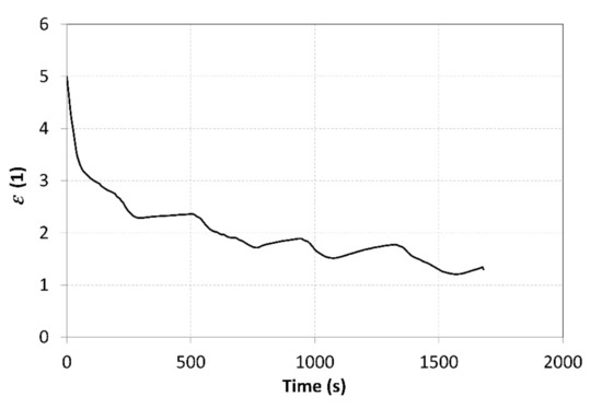
Figure 13.
Curve of the compression ratio throughout the compressor operation.
Abrupt drops in the ε value are not a desired phenomenon in real technical applications. They may be attributed to a lower quality of the heat exchangers in the MH tanks. Due to their small heat-transfer surface area and low thermal conductivity of the metal hydride powder, the heat exchangers did not allow a sufficiently intensive heat supply to the MH1 tank or heat removal from the MH2 tank. The curve of the relative pressures shown in Figure 9 indicates that the temperature of the MH2 tank ranged from 10 to 13 °C, but the relative pressure increased up to 0.6 MPa. These values do not correlate to the assumptions made for the proposed operating points, as shown in Figure 1. The average temperature of the metal hydride should acquire much higher values, significantly different from the temperatures measured on the surface of the tanks. This may be attributed, in particular, to the poor performance of the heat exchanger and local overheating of the alloy during the absorption. Another way to increase the compression ratio is by reducing the hydrogen flow rates; this, however, would reduce the overall compression efficiency because the heating power of the heat pump would remain unchanged.
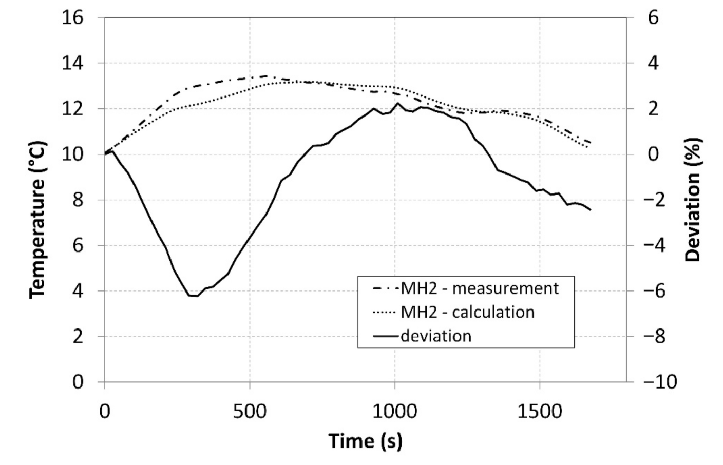
The analysis of the measured data, which were subsequently integrated in the model Described by Equation (12), facilitated calculating the values and plotting the curve of the temperature of the MH2 tank. Figure 14 shows a comparison of the measured surface temperatures of the tanks and the average temperature calculated while using the created model.
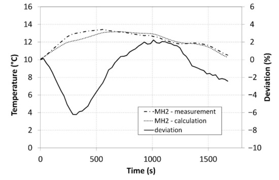
Figure 14.
A comparison of the measured and calculated tank temperatures.
The curves clearly indicate that the model exhibited a very high concordance with the measured data and that it may therefore facilitate better optimisation of the compressor in a designing stage. A maximum deviation reached 6%, and it is particularly the optimization of the internal heat exchanger and the improvement of the heat removal from the core of the MH material that may contribute to the overall enhancement of the compressor parameters and better accordance between the calculations and the measured data.
6. Conclusions
The publications that discuss the hydrogen compression using MH compressors primarily deal with higher ranges of the operating temperatures of the tanks. The investigating teams all share the same goal—to find a cheap source of heat and cold. The investigation into the concept of the MH compressor with the heat pump discussed in this paper was centred at the performance of the autonomous compressor that produced the range of operating temperatures by the thermal process that takes place inside the heat pump. The range of the operating temperatures of the tandem-arranged tanks was 12.3–54.9 °C, while the pressure was elevated from the average value of 0.56 to the value of 1.08 MPa.
Karagiorgis et al. [20] achieved the compressor’s specific productivity of 67.2 LH2·kg−1·h−1. In the experiment with the MH compressor and the heat pump, the achieved productivity, expressed as the compressor’s volumetric efficiency relative to the amount of the used alloy and the compression time, was 56.24 LH2·kg−1·h−1. In this regard, it should be noted that in this experiment with the heat pump, the difference in the operating temperatures was lower, 42.6 °C, i.e., 39% less than that applied in paper [20]. Nevertheless, the productivity achieved in this experiment was only 16% lower. Metal hydride compressors have the potential to become economically competitive alternatives to standard volume and centrifugal compressors, with a higher level of safety and a lower consumption of the input energy. The newly designed metal hydride compressor with a heat pump demonstrates the possibility of using suitable metal alloys to increase the hydrogen pressure through the use of thermal energy. The purpose of using the heat pump with the tandem-arranged MH tanks was to reduce the consumption of input electric energy while generating the required amount of thermal energy and refrigeration. The measurement data was used to validate the model describing the thermal balance over time, which must be known in order to design correctly the individual components of the MH compressor. On the other hand, the obtained values of the operating parameters helped to identify the key issues hindering the deployment of these types of compressors in real operations. In particular, the low thermal conductivity of the powder metal hydride leads to significant temperature differences in the alloy volume, and such differences result in the impaired heat removal by the internal heat exchanger. At the same time, it is necessary to maintain sufficient flow rates of the heat-transfer fluid in the heat exchanger in order for the overall heat transfer coefficient to reach the desired level. The achieved average value of the compression ratio, i.e., 2.0, indicates that the compressor can increase the hydrogen pressure: in ideal conditions, this value may be increased to 4 at temperatures ranging from 10 to 50 °C. The compression ratio may be further increased by replacing the heat pump that uses the R134a coolant with a heat pump that uses CO2 as the coolant. This may facilitate increasing the typical operating temperature range by more than 30 °C, while achieving higher values of the COP. The prospect for the future is to replace the MH tanks with the tanks containing more efficient internal heat exchangers, which will contribute to increasing the compression ratio. Additionally, in order to achieve higher operating pressures at the outlet from the MH compressor, the plan is to add a second stage with an interconnection between its heat circuit and the heat pump using CO2 as the working fluid; this will facilitate increasing the range of operating temperatures while maintaining a high COP.
Author Contributions
Conceptualisation, T.B.; Formal analysis, M.L., N.J.; Visualization, T.B., M.L.; Validation, T.B., N.J., M.L. All authors have read and agreed to the published version of the manuscript.
Funding
This paper was written with the financial support from the VEGA granting agency within the project solutions No. 1/0626/20 and No. 1/0532/22 from the KEGA granting agency within the project solutions No. 012TUKE-4/2022 and with financial support from the granting agency APVV within the Project Solution No. APVV-15-0202 and APVV-21-0274.
Institutional Review Board Statement
Not applicable.
Informed Consent Statement
Not applicable.
Data Availability Statement
Not applicable.
Conflicts of Interest
The authors declare no conflict of interest.
Nomenclature
| Symbols | |
| ε | compression ratio |
| Σ(mi·ci) | overall heat capacity of the MH tank, including the integrated heat exchanger and the absorbed hydrogen, (J·K−1) |
| ΔT | temperature difference between the working isotherms, (K) |
| qdes H2 | heat of reaction in hydrogen desorption, (J·m−3) |
| ΔVdes H2 | amount of the hydrogen released due to a temperature increase by ΔT, (m3) |
| pD | hydrogen pressure in point D, (Pa) |
| pB | hydrogen pressure in point B, (Pa) |
| qabs H2 | heat of reaction in hydrogen absorption, (J·m−3) |
| ΔVabs H2 | amount of the absorbed hydrogen at a temperature decreases by ΔT, (m3) |
| change in the mass concentration of the stored hydrogen, (1) | |
| hydrogen volume, (m3) | |
| hydrogen density, (kg·m−3) | |
| mass of the metal hydride alloy, (kg) | |
| PG | heating power generated during the hydrogen absorption, (W) |
| Pins | heating power received from the surrounding environment through the insulation, (W) |
| Phe | power from the heat exchanger, (W) |
| t | temperature, (°C) |
| τ | time, (s) |
| Qmw | mass flow rate of the heat-transfer fluid through the heat exchanger, (kg·s−1) |
| cw | heat capacity of the heat-transfer fluid, (J·kg−1·K−1) |
| tw-out | fluid temperature at the outlet from the heat exchanger, (°C) |
| tw-in | fluid temperature at the inlet to the heat exchanger, (°C) |
| Δt | difference in the tank temperature, (°C) |
| Δτ | time difference, (s) |
| Acronyms | |
| MH | Metal Hydride |
| MHHC | Metal-hydride-based hydrogen compressor |
| COP | Coefficient of Performance |
| PCI | Pressure-Concentration Isotherms |
| PT | TEC1-12708 Peltier modules |
References
- Wei, S.; Hikmati, J.; Blalkin, V.B.; Kosinski, P. Experimental study of hydrogen production using electrolyte nanofluids with a simulated light source. Int. J. Hydrogen Energy 2022, 47, 7522–7534. [Google Scholar] [CrossRef]
- Collodi, G.; Wheeler, F. Hydrogen production via steam reforming with CO2 capture. Chem. Eng. Trans. 2010, 19, 37–42. [Google Scholar] [CrossRef]
- Ji, M.; Wang, J. Review and comparison of various hydrogen production methods based on costs and life cycle impact assessment indicators. Int. J. Hydrogen Energy 2021, 46, 38612–38635. [Google Scholar] [CrossRef]
- Elberry, M.A.; Thakur, J.; Veysey, J. Seasonal hydrogen storage for sustainable renewable energy integration in the electricity sector: A case study of Finland. J. Energy Storage 2021, 44, 103474–103488. [Google Scholar] [CrossRef]
- Muhammed, N.S.; Haq, B.; Shehri, A.D.; Al-Ahmed, A.; Rahman, M.M.; Zaman, E. A review on underground hydrogen storage: Insight into geological sites, influencing factors and future outlook. Energy Rep. 2022, 8, 461–499. [Google Scholar] [CrossRef]
- Abohamzeh, E.; Salehi, F.; Sheikholeslami, M.; Abbassi, R.; Khan, F. Review of hydrogen safety during storage, transmission, and applications processes. J. Loss Prev. Proc. Ind. 2021, 72, 104569–104588. [Google Scholar] [CrossRef]
- Hassan, I.A.; Ramadan, S.H.; Saleh, A.M.; Hissel, D. Hydrogen storage technologies for stationary and mobile applications: Review, analysis and perspectives. Renew. Sustain. Energy Rev. 2021, 149, 111311–111338. [Google Scholar] [CrossRef]
- Tsujimura, T.; Dimitriou, P. A review of hydrogen as a compression ignition engine fuel. Int. J. Hydrogen Energy 2017, 42, 24470–24486. [Google Scholar] [CrossRef]
- Durmus, G.N.B.; Colpan, C.O.; Devrim, Y. A review on the development of the electrochemical hydrogen compressors. J. Power Sources 2021, 494, 229743–229756. [Google Scholar] [CrossRef]
- Ishaq, H.; Dincer, I.; Crawford, C. A review on hydrogen production and utilization: Challenges and opportunities. Int. J. Hydrogen Energy 2021, in press. [Google Scholar] [CrossRef]
- Sinay, J.; Brestovič, T.; Markovič, J.; Glatz, J.; Gorzás, M.; Vargová, M. Analysis of the Risk of hydrogen leakage from hydrogen powered cars and their possible impact on automotive Market Share Increase. Appl. Sci. 2020, 10, 4292. [Google Scholar] [CrossRef]
- Brestovič, T.; Lázár, M.; Jasminská, N.; Živčák, J.; Tóth, L.; Dobáková, R.; Duda, F.; Kmeťová, Ľ.; Bednárová, Ľ. Analysis of the heat balance of a metal hydride separator used for the separation of hydrogen from syngas. Processes 2021, 9, 251. [Google Scholar] [CrossRef]
- Brestovič, T.; Lázár, M.; Jasminská, N.; Živčák, J.; Hudák, R.; Tóth, L.; Dobáková, R. The Determination of the Inward Leakage through the Skin–Facepiece Interface of the Protective Half-Mask. Appl. Sci. 2021, 11, 8042. [Google Scholar] [CrossRef]
- Lototskyy, M.V.; Yartys, V.A.; Pollet, B.G.; Bowman, R.C., Jr. Metal hydride hydrogen compressors: A review. Int. J. Hydrogen Energy 2014, 39, 5818–5851. [Google Scholar] [CrossRef] [Green Version]
- Nguyen, Q.H.; Shabani, B. Review of metal hydride hydrogen storage thermal management for use in the fuel cell systems. Int. J. Hydrogen Energy 2021, 46, 31699–31726. [Google Scholar] [CrossRef]
- Tarasov, B.P.; Fursikov, P.V.; Volodin, A.A.; Bocharnikov, M.S.; Shimkus, Y.Y.; Kashin, A.M.; Yartys, V.A.; Chidziva, S.; Pasupathi, S.; Lototskyy, M.V. Metal hydride hydrogen storage and compression systems for energy storage technologies. Int. J. Hydrogen Energy 2021, 46, 13647–13657. [Google Scholar] [CrossRef]
- Peng, Z.; Li, Q.; Ouyang, L.; Jiang, W.; Chen, K.; Wang, H.; Liu, J.; Li, Z.; Wang, S.; Zhu, M. Overview of hydrogen compression materials based on a three-stage metal hydride hydrogen compressor. J. Alloy. Compd. 2022, 895, 162465–162488. [Google Scholar] [CrossRef]
- Laurencelle, F.; Dehouche, Z.; Morin, F.; Goyette, J. Experimental study on a metal hydride based hydrogen compressor. J. Alloy. Compd. 2009, 475, 810–816. [Google Scholar] [CrossRef] [Green Version]
- Kelly, N.A.; Girdwood, R. Evaluation of a thermally-drived metal-hydride-based hydrogen compressor. Int. J. Hydrogen Energy 2012, 37, 10898–10916. [Google Scholar] [CrossRef]
- Karagiorgis, G.; Christodoulou, C.N.; von Storch, H.; Tzamalis, G.; Deligiannis, K.; Had-jipetrou, D.; Odysseos, M.; Roeb, M.; Sattler, C. Design, development, construction and operation of a novel metal hydride compressor. Int. J. Hydrogen Energy 2017, 42, 12364–12374. [Google Scholar] [CrossRef]
- Sdanghi, G.; Maranzana, G.; Celzard, A.; Fierro, V. Towards Non-Mechanical Hybrid Hydrogen Compression for Decentralized Hydrogen Facilities. Energies 2020, 13, 3145. [Google Scholar] [CrossRef]
- Stamatakis, E.; Zoulias, E.; Tzamalis, G.; Massina, Z.; Analytis, V.; Christodoulou, C.; Stubos, A. Metal hydride hydrogen compressors: Current developments & early markets. Renew. Energy 2018, 127, 850–862. [Google Scholar] [CrossRef]
- Lototskyy, M.V.; Yartys, V.A.; Tarasov, B.P.; Davids, M.W.; Denys, R.V.; Tai, S. Modelling of metal hydride hydrogen compressors from thermodynamics of hydrogen—Metal interactions viewpoint: Part I. Assessment of the performance of metal hydride materials. Int. J. Hydrogen Energy 2021, 46, 2330–2338. [Google Scholar] [CrossRef]
- Lototskyy, M.V.; Yartys, V.A.; Tarasov, B.P.; Denys, R.V.; Eriksen, J.; Bocharnikov, M.S.; Tai, S.; Linkov, V. Modelling of metal hydride hydrogen compressors from thermodynamics of hydrogen—Metal interactions viewpoint: Part II. Assessment of the performance of metal hydride compressors. Int. J. Hydrogen Energy 2021, 46, 2339–2350. [Google Scholar] [CrossRef]
- Pačaiová, H.; Oravec, M.; Smelko, M.; Lipovsky, P.; Forraj, F. Extra low frequency magnetic fields of welding machines and personal safety. J. Elect. Eng. 2018, 69, 493–496. [Google Scholar] [CrossRef] [Green Version]


Publisher’s Note: MDPI stays neutral with regard to jurisdictional claims in published maps and institutional affiliations. |
© 2022 by the authors. Licensee MDPI, Basel, Switzerland. This article is an open access article distributed under the terms and conditions of the Creative Commons Attribution (CC BY) license (https://creativecommons.org/licenses/by/4.0/).