Article

Investigation of Load Capacity of High-Contact-Ratio Internal Spur Gear Drive with Arc Path of Contact

School of Mechanical Engineering and Automation, Beihang University, Beijing 100191, China
*
Author to whom correspondence should be addressed.
Appl. Sci. 2022, 12(7), 3345; https://doi.org/10.3390/app12073345
Submission received: 8 March 2022 / Revised: 23 March 2022 / Accepted: 24 March 2022 / Published: 25 March 2022

Abstract

:

Featured Application

The research within this paper can provide a feasible, technical means for the design of new high-contact-ratio gears and can effectively promote the progress of gear transmission technology. The research results can be applied to the transmission systems of complex equipment such as tanks, armored vehicles, and ships, which is of great significance to improving their performance.

Abstract

Tooth root bending stress and surface contact stress are two major determinants of the load carrying capacity of gear drives. Generally, a high contact ratio has the potential to enhance the gear strength. In this paper, the basic procedures and methods for constructing a high-contact-ratio (HCR) internal spur gear pair with the arc path of the contact are presented. The effects of design and modification parameters such as deflection angle, modification angle, and addendum coefficient on gear drive are analyzed in detail based on 2D finite-element models (FEMs). A comparison of experimental and finite-element analyses (FEA) of the bending stress, contact stress, and contact ratio between HCR and involute internal spur gear drives was conducted to demonstrate the advantages of the HCR gear drive in terms of load capacity. The results show that appropriately increasing the deflection angle and addendum coefficient is beneficial for reducing bending and contact stresses. It was also observed that the bending and contact stresses of a HCR pinion are lower than those of an involute one. Moreover, the contact ratio increases with input torque.

1. Introduction

Gear drives are widely used in fields such as mechanical equipment, transportation, aviation engines, wind turbines, and the marine field. Internal gear drives have the advantages of compact structure and small volume [1,2,3]. They can not only become a transmission form alone, but they are also an important part of planetary gear sets. As machinery and equipment in the above-mentioned fields continue to move towards high speed and heavy loads, gear drives are often required to have a higher load-carrying capacity. Improving gear modules and increasing gear width are frequently used to advance the load-carrying capacity of gear drives. However, these methods both have great limitations, such as increasing the size and reducing the power-to-weight ratio [4,5].
Root bending and surface contact strength determine the working capacity and service life of gear drives. In order to enhance the bending and contact strength, profile modification is often carried out [6]. Much research on profile modification and its influence on gear drives has been developed. Li [7] investigated the bending stress and contact stress of a spur gear pair with tooth modifications. Other work by the same author discussed the effects of addendum on the gear strength [8]. San et al. [9] revealed that the circular root filet exhibited higher bending strength than the standard trochoidal root filet by the way of FEA. Maper et al. [10] numerically analyzed the contributions of linear and parabolic tip relief on contact and filet stresses. Dong et al. [11] used genetic algorithms and FEA to build the optimal gear root profile with higher filet load capacity (Figure 1). Sánchez et al. [12] delineated the contact conditions with modified teeth under applied load.
Even though most profile modifications can improve the stress state of gear teeth to a certain extent, profile modifications have limited effects on improving the contact ratio of involute gear pairs, which is not conducive to the further enhancement of load-carrying capacity. The most effective way to improve the load-carrying capacity is to enlarge the contact ratio by customizing non-standard gears. Nguyen [13] obtained a contact ratio of 2 or higher by varying the addendum ratio over the range 1.3 to 1.4. Lin et al. [14] introduced a computer-aided design procedure to decrease the dynamic load of HCR gear drives considering a range of applied loads. Kape [15] used two different base circles to build involute tooth surfaces on both sides to increase the load capacity. Mar et al. [16] carried out a parametric study on gear strength of HCR spur gear drives with asymmetric tooth surfaces (Figure 2 and Figure 3). Mu [17] adopted a direct gear-design approach considering the desired input parameters for the asymmetric internal spur gear drives to improve the load-carrying capacity. However, methods such as addendum extended and pressure-angle adjustment are both passive design methods, which cannot achieve the purpose of actively controlling the tooth profile [18,19,20,21,22]. Furthermore, the above methods all have limited ability to increase the gear contact ratio. To overcome this limitation, Wang et al. [23,24] proposed a HCR gear-drive design approach using the directly designed path of contact, and FEM was used to study the root bending strength, surface contact strength, and meshing stiffness.
A circular-arc gear refers to a point-meshing gear with a concave–convex tooth profile, in which the pinion is a convex circular-arc tooth profile and the large gear is a concave circular-arc tooth profile, which is called single circular-arc gear transmission. The large and small gears are made into convex circular-arc tooth profiles outside of their pitch circles, and the parts within their pitch circles are made into concave circular-arc tooth profiles, which is called double-circular-arc gear transmission [25]. Scholars worldwide have conducted a lot of research on the modification of convex and concave tooth profiles and their influence on gear transmission. Hu et al. optimized the tooth parameters of a double-circular-arc gear by using the goal reaching method, and then compared the maximum bending stress before and after optimization with the ANSYS finite-element analysis software [26]. In the optimization design of double-circular-arc gear transmission, fuzzy reliability optimization design, multi-objective particle swarm optimization method, finite-element optimization method of function approximation, and optimization methods organically combining multi-objective particle swarm optimization algorithm, uniform experimental design, robust design, and sensitivity analysis are generally adopted [27,28,29,30,31,32,33]. The meshing contact between circular-arc gears is highly nonlinear. Most often, the finite-element method is used to analyze the tooth surface contact stress and tooth root bending stress of circular-arc gears, and to finally guide the analysis results to practice [34,35,36,37]. Jiang et al. propose a novel bidirectional conjugate design method which aims to solve the uncertain problem of the conjugated convex circular-arc tooth profile of a circular spline existing in the widely used unidirectional conjugate design method of double-circular-arc tooth profile [38]. Zhang et al., established the finite-element model of a double-circular-arc planetary gear transmission system by using the finite-element method, and carried out transient dynamic analysis, obtained the variation curves of equivalent stress and contact stress during the movement of the transmission system, and carried out fatigue life analysis in combination with a fatigue tool [39].
To sum up, the research on HCR gears with a circular meshing line is mainly based on the design and simulation of basic parameters and the processing of basic samples. However, these studies do not further discuss the influence of changing design and modification parameters (root deflection angle, correction angle, and addendum coefficient) on the bearing capacity of gears. At the same time, the relevant design and simulation results lack transmission test verification and comparative analyses of test data and simulation data. Therefore, it is necessary to carry out research on these aspects to fill the research gaps.
In this paper, the positive addendum modification and the directly designed path of contact are combined to construct the HCR gear drive. Parametric studies on bending and contact stresses are carried out for the HCR internal gear drive based on FEMs. To more intuitively show the superiority of enhancement on load-carrying capacity of HCR internal gear drives, the experimental comparison of bending stress and contact ratio with involute internal gear drives is conducted under the same assembly conditions, tooth number, gear ratio and working conditions. The bending stress and contact ratio are obtained indirectly by the strain gauge technique. In addition, the comparison of contact stress is probed numerically by FEA. Furthermore, the effects of the input torque and rotational speed on contact ratio are also considered. The main process of this paper is shown in Figure 4.

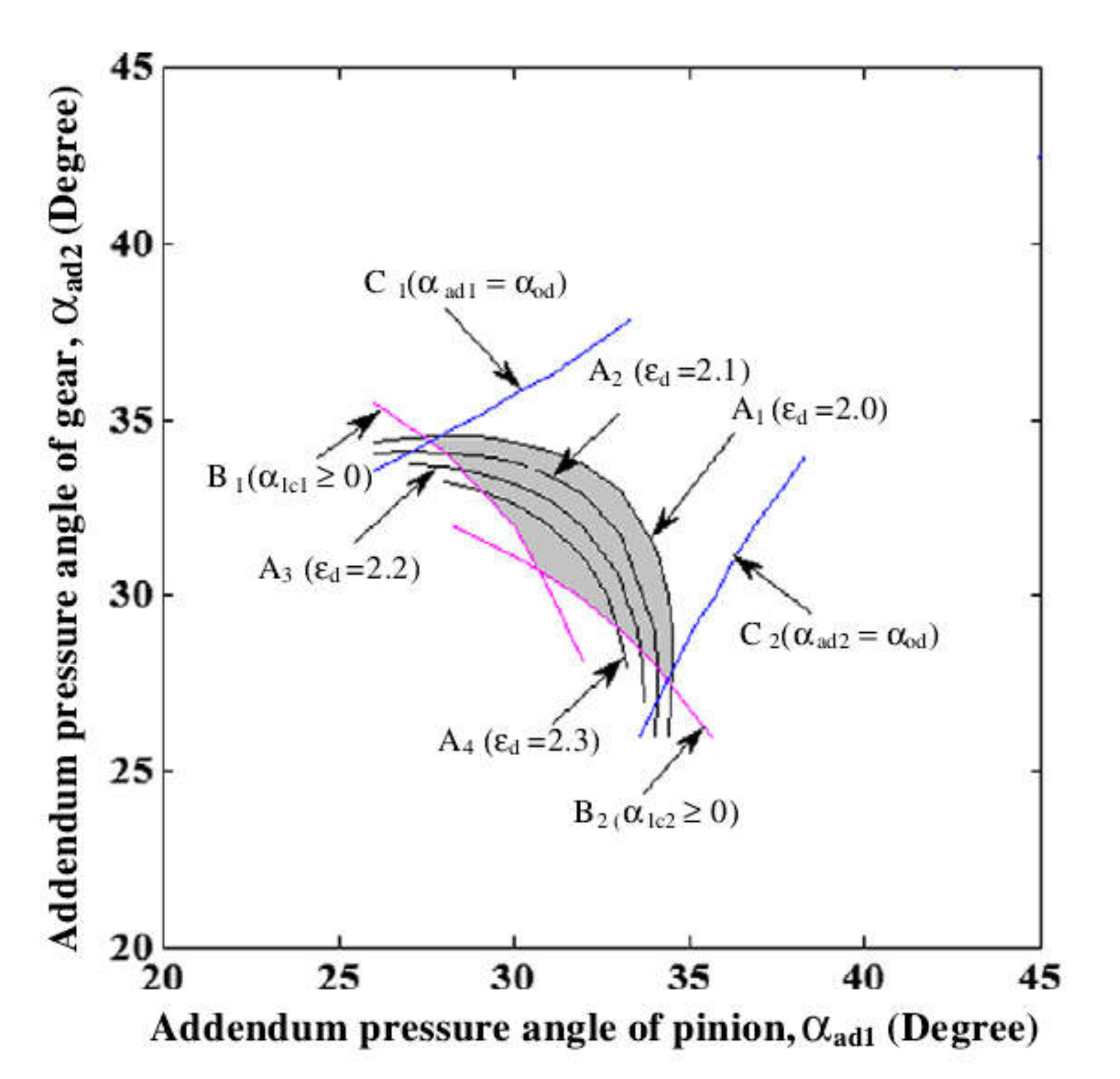
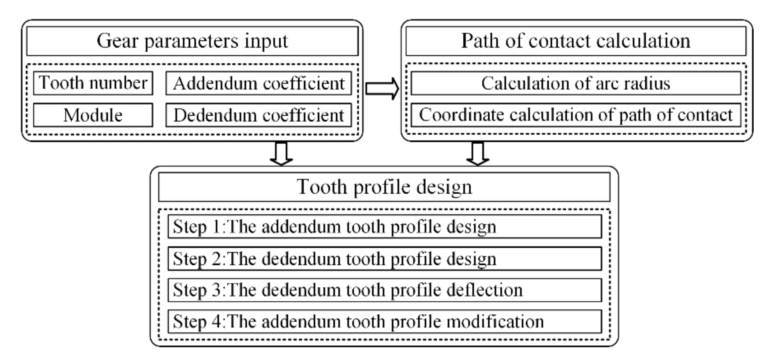
2. Design Approach for HCR Internal Spur Gear Drive

The profile-design method of the HCR internal spur gear drive based on the arc path of contact and high addendum coefficient broke the contact ratio limit in involute gear design. The detailed design procedure is shown in Figure 5.

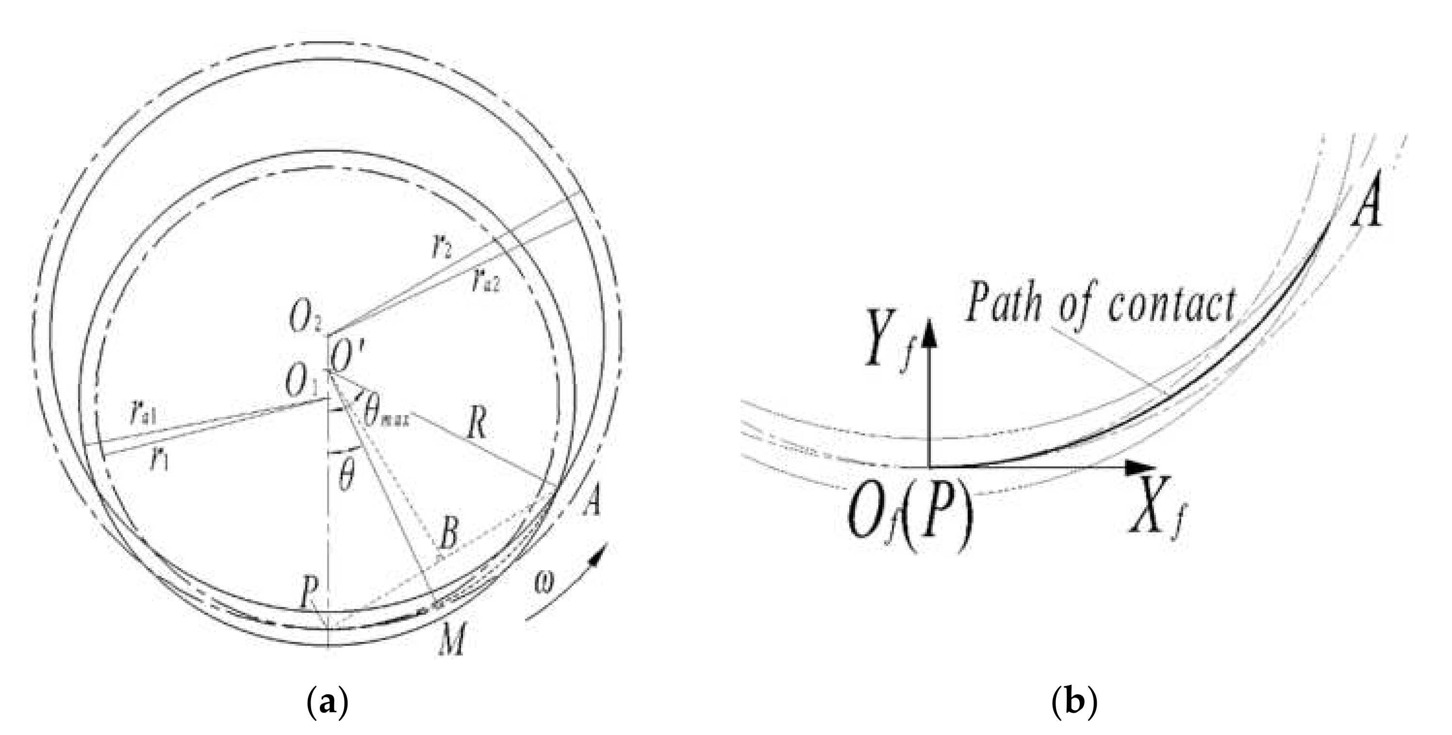
2.1. Path of Contact

The path of contact always passes through the tangent point of the pitch circle of two meshing gears and must be between the two addendum circles according to the gear mesh principle. In Figure 6, two gears are centered at point O 1 and O 2 , pitch circles with radii r 1 and r 2 are tangent at point P, and the addendum circles with radii r a 1 and r a 2 intersect at point A on one side. Points P and A are connected to form the mid-perpendicular line P A ¯ . The mid-perpendicular line P A ¯ and line O 1 O 2 ¯ intersect at the center O of the arc path of contact. The fixed coordinate system S f :   { O f , X f , Y f } is established with point P as the origin, the center of arc PA is located on the Y f axis, and the radius R of the arc path of contact PA can be calculated. Finally, the arc path of contact under coordinate system S f is presented in Equation (1) [23]:
x f = R sin θ y f = R 1 c o s θ θ 0 ,   θ m a x  
where x f and y f are coordinate values of the meshing point under coordinate system S f .

2.2. Mathematical Equations of Tooth Profile

2.2.1. Addendum Tooth Profile

The gear mesh principle and law of coordinate transformation are used to obtain addendum tooth profiles of the pinion and internal gear according to the known arc path of contact, which can be given in Equations (2) and (3), respectively [23,24]:
r a 1 θ = R sin θ 1 R / r 1 + R r 1 sin θ R / r 1 R cos θ 1 R / r 1 + R r 1 cos θ R / r 1 1
r a 2 θ = R sin θ 1 R / r 2 + R r 2 sin θ R / r 2 R cos θ 1 R / r 2 + R r 2 cos θ R / r 2 1

2.2.2. Dedendum Tooth Profile

The tooth profile below pitch point does not participate in meshing, whose design criterion is to increase the bending strength of the gear tooth as much as possible. In this paper, the tooth profiles meshed with the addendum tooth profile of the internal gear and pinion are selected as the dedendum tooth profiles of the pinion and internal gear, respectively. The dedendum tooth profile of the pinion and internal gear are defined through Equations (4) and (5) [23,24]:
r f 1 θ = r 1 r 2 + R sin r 2 R / r 1 θ r 2 R sin r 1 r 2 + R / r 1 θ r 1 r 2 + R cos r 2 R / r 1 θ r 2 R cos r 1 r 2 + R / r 1 θ 1
r f 2 θ = r 2 r 1 + R sin r 1 R / r 2 θ r 1 R sin r 2 r 1 + R / r 2 θ r 2 r 1 + R cos r 1 R / r 2 θ r 1 R cos r 2 r 1 + R / r 2 θ 1

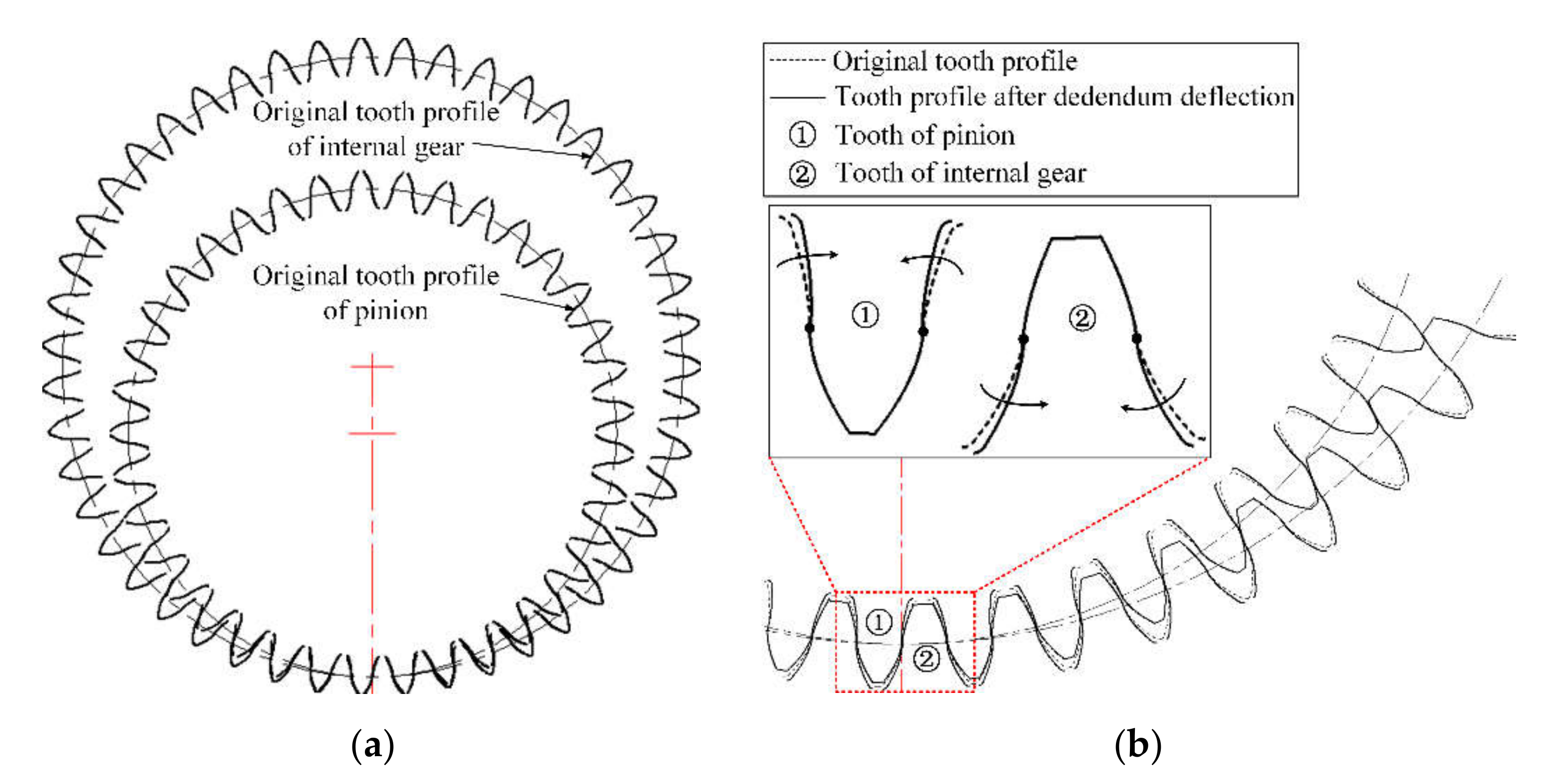
2.2.3. Deflection of Dedendum Tooth Profile

After the above derivation, the basic tooth profile is obtained in Figure 7. The dedendum tooth profiles of the internal gear need to be deflected inward by a certain angle γ around the pitch point (as can be seen in Figure 7, ①) to prevent the engagement between the dedendum tooth profile of the internal gear and the addendum tooth profile of the pinion. Furthermore, the addendum tooth profile of the internal gear not only meshes with the dedendum tooth profile of the pinion in the mesh-in period, but also does so in the mesh-out period [23]. Since the gear drive process accompanies sliding, it will generate a large amount of heat if the mesh period is too long for a tooth profile, which is not conducive to the contact strength and wear resistance of the tooth surface. Therefore, like the dedendum tooth profile of the internal gear, the dedendum tooth profile of the pinion is also deflected inward by a certain angle γ around the pitch point to avoid engagement between the addendum tooth profile of the internal gear and the dedendum tooth profile of the pinion (as can be seen in Figure 7, ②).

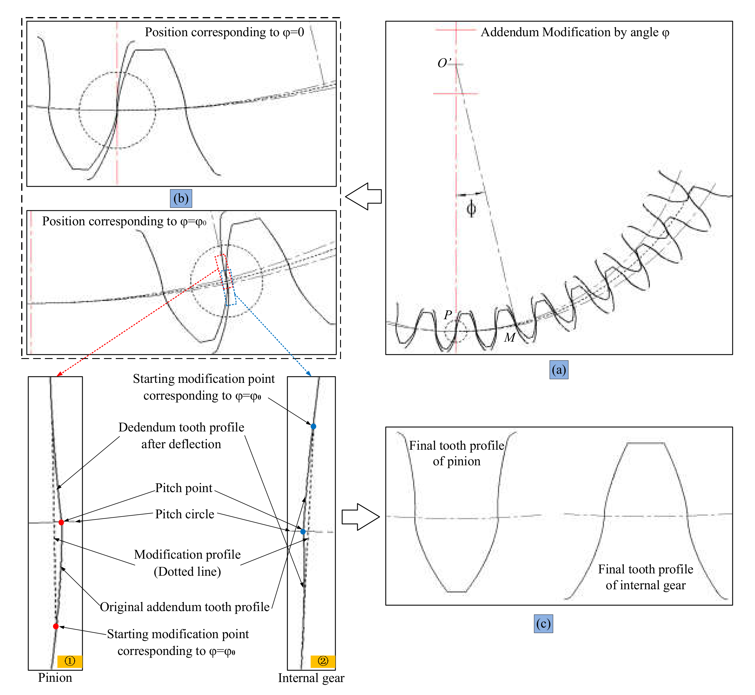
2.2.4. Modification of Addendum Tooth Profile

The position of the pitch point will become sharp and will no longer be smooth after the deflection of the dedendum tooth profile. Therefore, the area near the pitch point needs to be modified to avoid contact stress concentration at the pitch point. First, a modification angle φ is defined, namely, the angle between O M ¯ and the Y f axis, where point M is located on the path of contact and corresponds to the starting modification point of the addendum tooth profile, as shown in Figure 8. After that, the tooth profile belonging to the path of contact PM is modified. A micro-line segment located inside the pitch point is used to replace the original tooth profile at this position. One end of the micro-line segment is connected with the starting modification point of the addendum tooth profile, and the other end is tangent to the dedendum tooth profile. The final tooth profiles are obtained as shown in Figure 8.

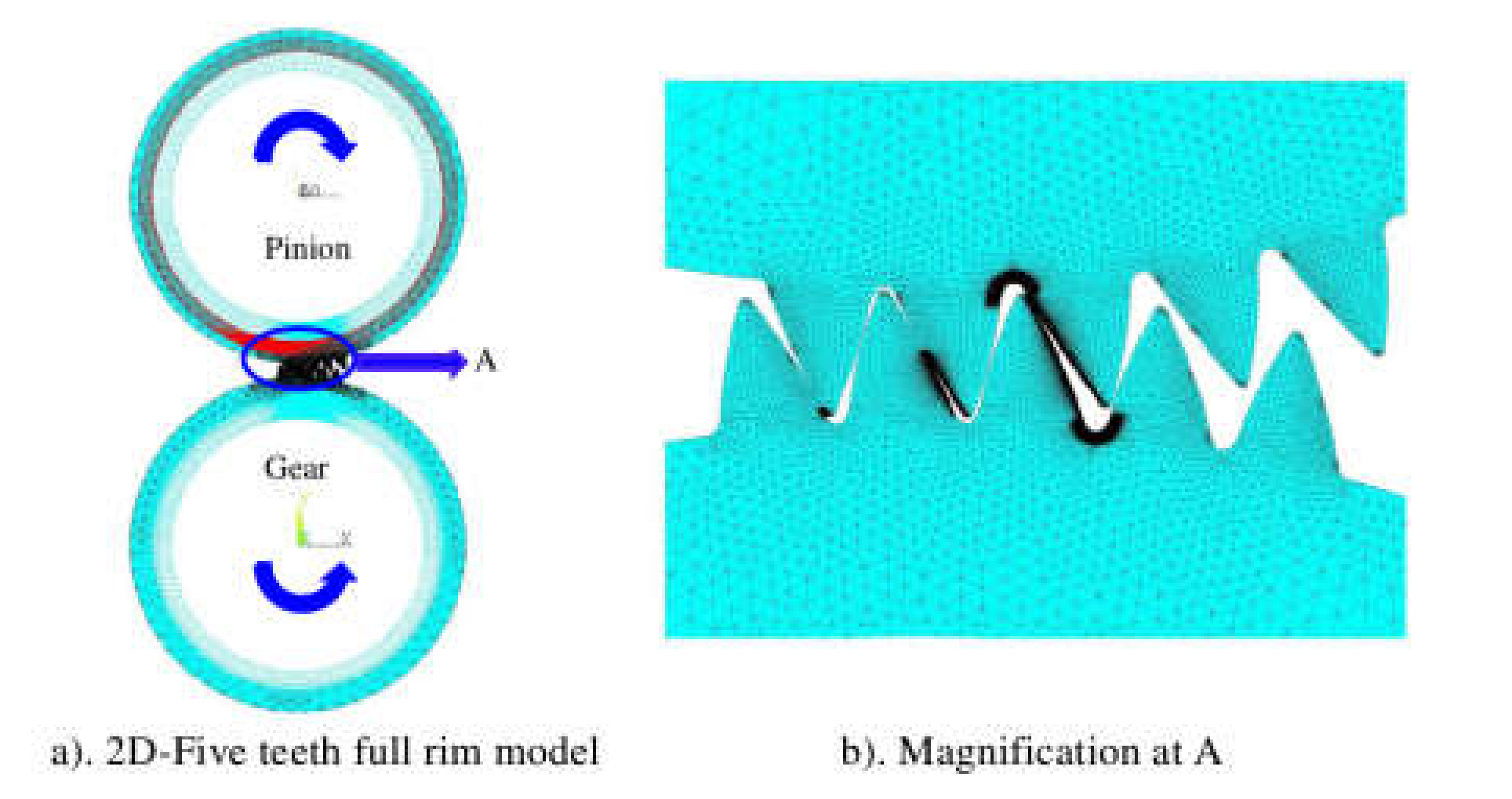
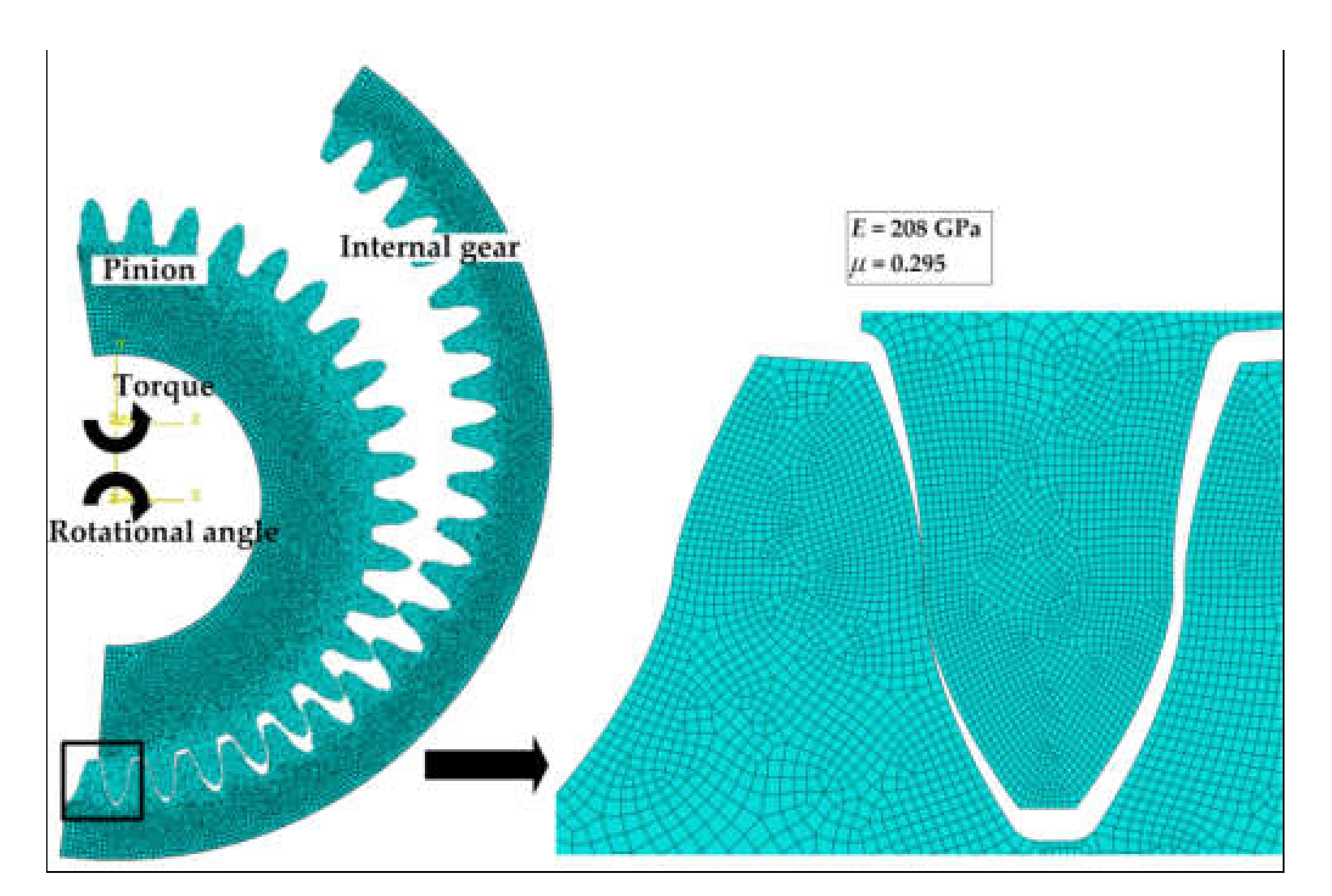
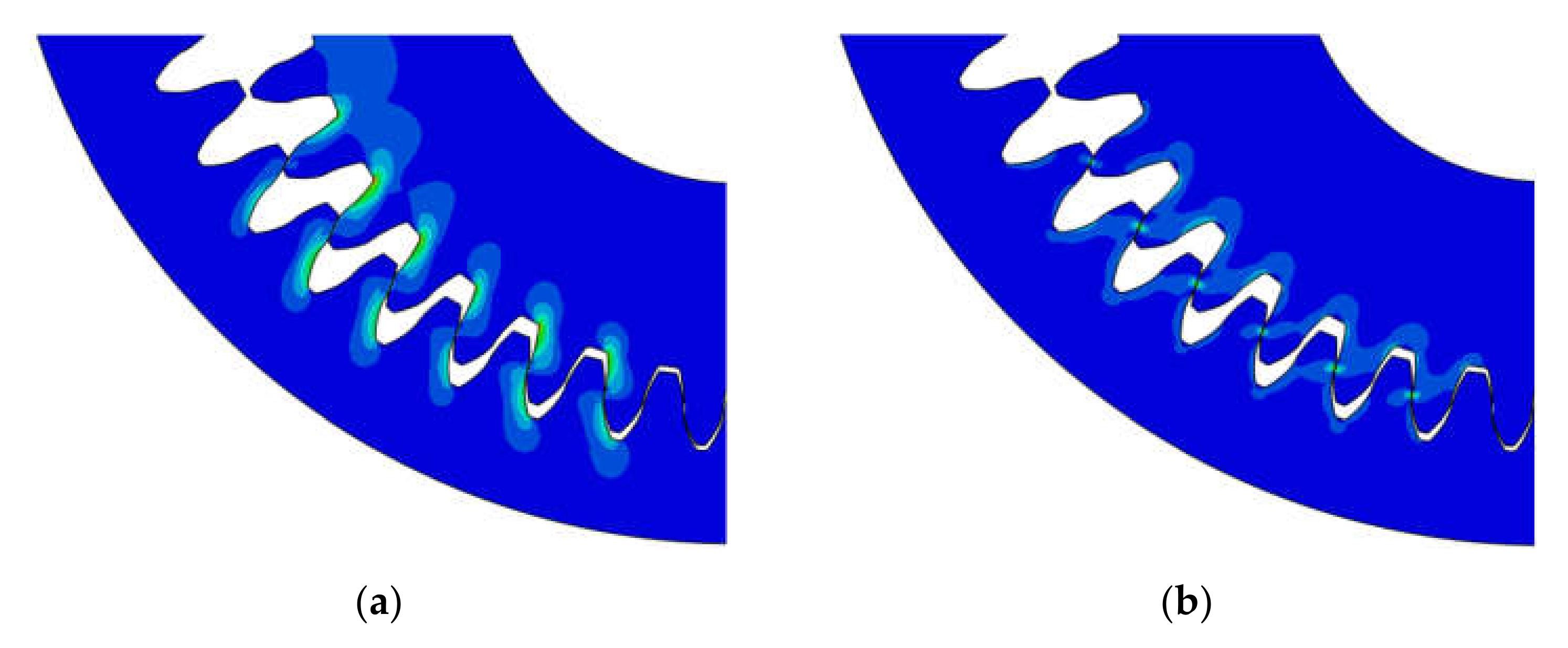
3. Finite-Element Modeling

Two-dimensional 20-teeth FEMs (as shown in Figure 9) are developed for parametric study considering the mesh cycle of one tooth from mesh-in to mesh-out by using ABAQUS 6.14. The element type CPS4R is selected. The contact surface of the internal gear is the master surface and the contact surface of the pinion is the slave surface. Assume that hard contact occurs between the tooth surfaces and the sliding friction coefficient is 0.1. Further, a very fine grid has been applied at the pinion and internal gear teeth for more accurate calculation results.
The boundary conditions are as follows:
  • The centers of the pinion and internal gear are bound to the inner and outer periphery surface, respectively.
  • All the directions of the pinion and internal gear are constrained except for the rotational direction.
  • There are two analysis steps. A small angle in the rotational direction is applied for the pinion to establish contact in the first step.
  • The rotational angle is set to 3.4 rad at the center of the pinion, and 5 Nm of torque (T) is applied at the center of the internal gear in the opposite direction during the second step.
After the HCR gear meshing starts, along the meshing line PA (Figure 6b) of the top tooth profile of the pinion and the top tooth profile of the internal gear, the pinion drives the internal gear to move, it starts to mesh with the top tooth profile of the internal gear from the part near the tooth root of the top tooth profile of the pinion (direction from tooth profile node to tooth profile vertex), and exits the meshing at the top of the pinion and the internal gear.

4. Parametric Study on HCR Internal Spur Gear Drives

To investigate the influence of root deflection angle, modification angle, and addendum coefficient, other HCR gear-drive design parameters are kept constant and listed in Table 1. According to the control variable method, nine groups of comparisons are listed in Table 2, in which numbers 1–3 discuss the influence of deflection angle, numbers 4–6 the influence of modification angle, and numbers 7–9 the influence of the addendum coefficient. Different tooth profiles of the HCR pinion for use in parametric study are shown in Figure 10. The maximum bending stress σ f m a x at the filet region and maximum contact stress σ h m a x at the tooth flank are both estimated through FEA, and the stress maps of 2D FEMs are shown in Figure 11.

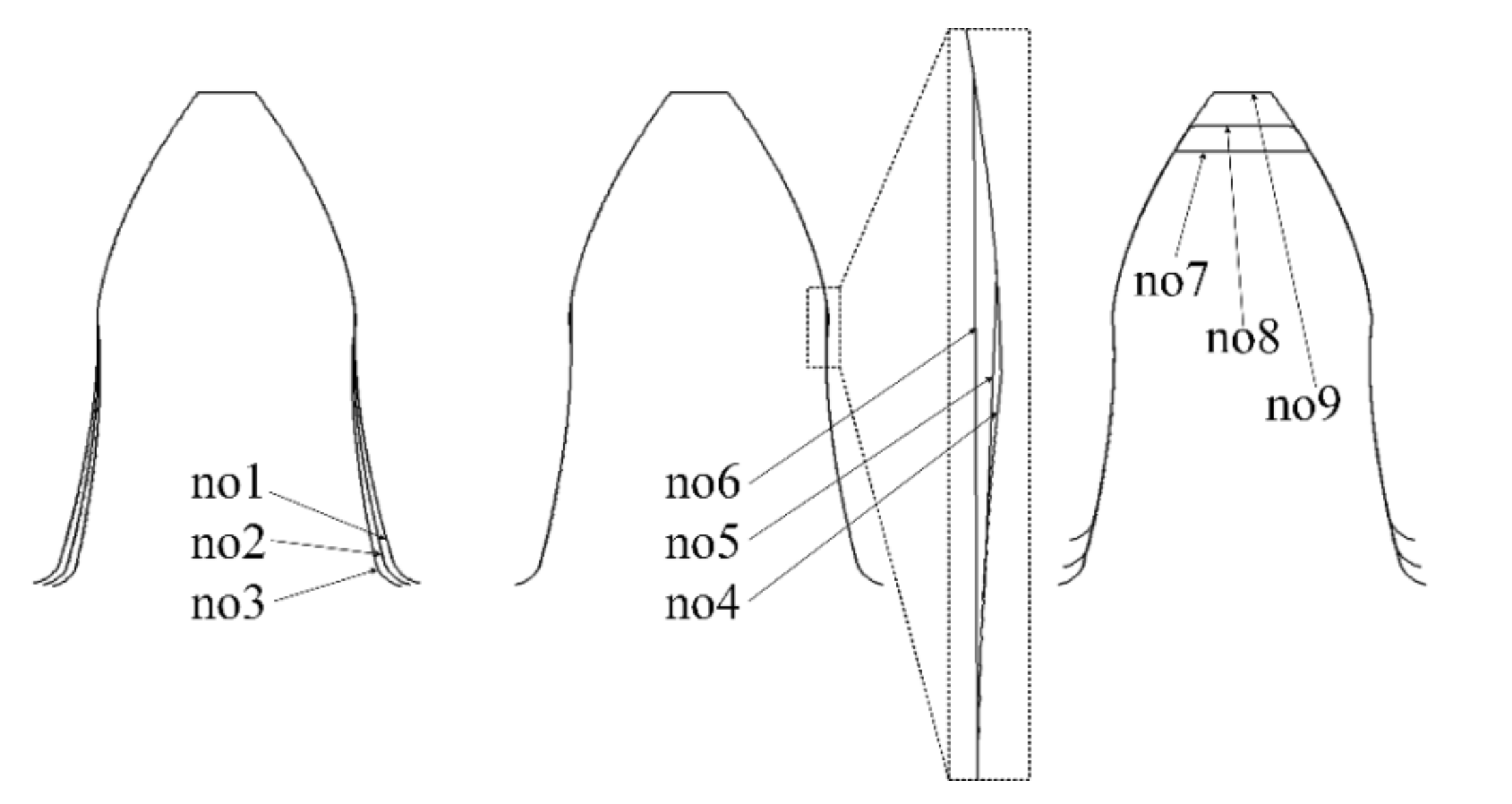
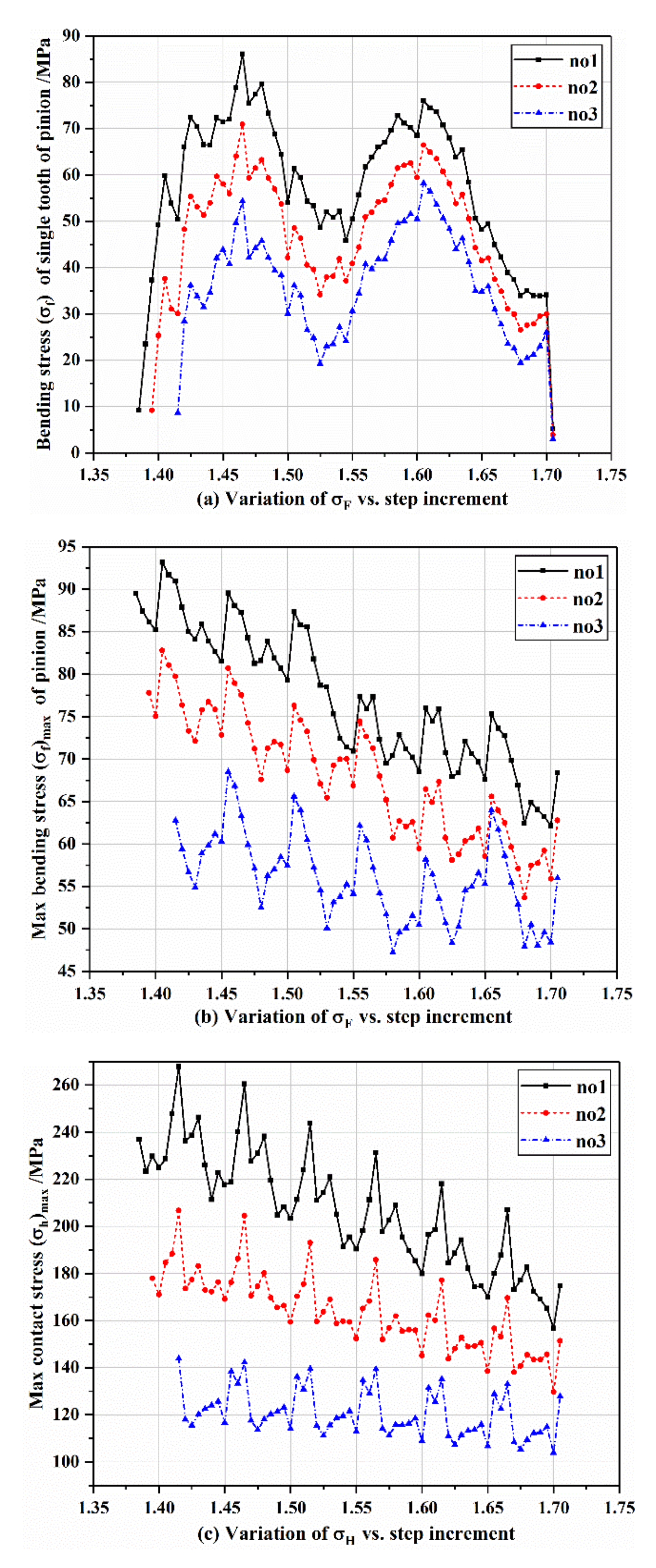
4.1. Influence of Root Deflection Angle

The influence of root deflection angle on bending and contact stresses is shown in Figure 12a–c. Figure 12a shows the variation in bending stress of a single pinion tooth against a step increment for a mesh cycle from mesh-in to mesh-out. In the complete cycle of single-tooth meshing, the first maximum bending stress peaks in groups 1–3 are 86 Mpa, 71 Mpa, and 55 MPa, respectively. The stress value for the 6° deflection angle in group 2 is 17.4% lower than that of the 4° deflection angle in group 1, and the 8° deflection angle in group 3 is 36% lower than that in group 1. The second maximum bending stress peaks are 75 Mpa, 65 Mpa, and 59 Mpa, respectively. The stress value for the 6° deflection angle in group 2 is 13.3% lower than that of the 4° deflection angle in group 1, and the 8° deflection angle in group 3 is 21.3% lower than that of group 1. It can be seen that the bending stress of the single tooth decreases with the increase in tooth root deflection angle. The maximum bending and contact stresses of the whole gear drive against a step increment for a mesh cycle are shown in Figure 12b,c. When multiple teeth enter the meshing state, the maximum bending stress of the first stress peaks in groups 1–3 are 93 Mpa, 83 Mpa, and 68 Mpa, respectively. The second group is 10.8% lower than the first group, and the third group is 26.9% lower than the first group (Figure 12b). The maximum contact stresses of the first stress peaks in groups 1–3 are 280 Mpa, 210 Mpa, and 142 Mpa, respectively. The second group is 25% lower than the first group, and the third group is 49.3% lower than the first group (Figure 12c). It can be seen that the maximum bending stress and contact stress gradually decrease with the increase in tooth root deflection angle. The larger the tooth root deflection angle is, the smaller the maximum bending stress and contact stress are. It can be found that all stresses decrease significantly as the deflection angle increases due to the decrease in root bending stiffness. However, the deflection angle should not be too large, otherwise it will reduce the root bending strength. Furthermore, in the middle of a mesh cycle, the bending stress of a single tooth decreases clearly and then increases again; namely, two stress peaks appear in a mesh cycle for a single tooth.

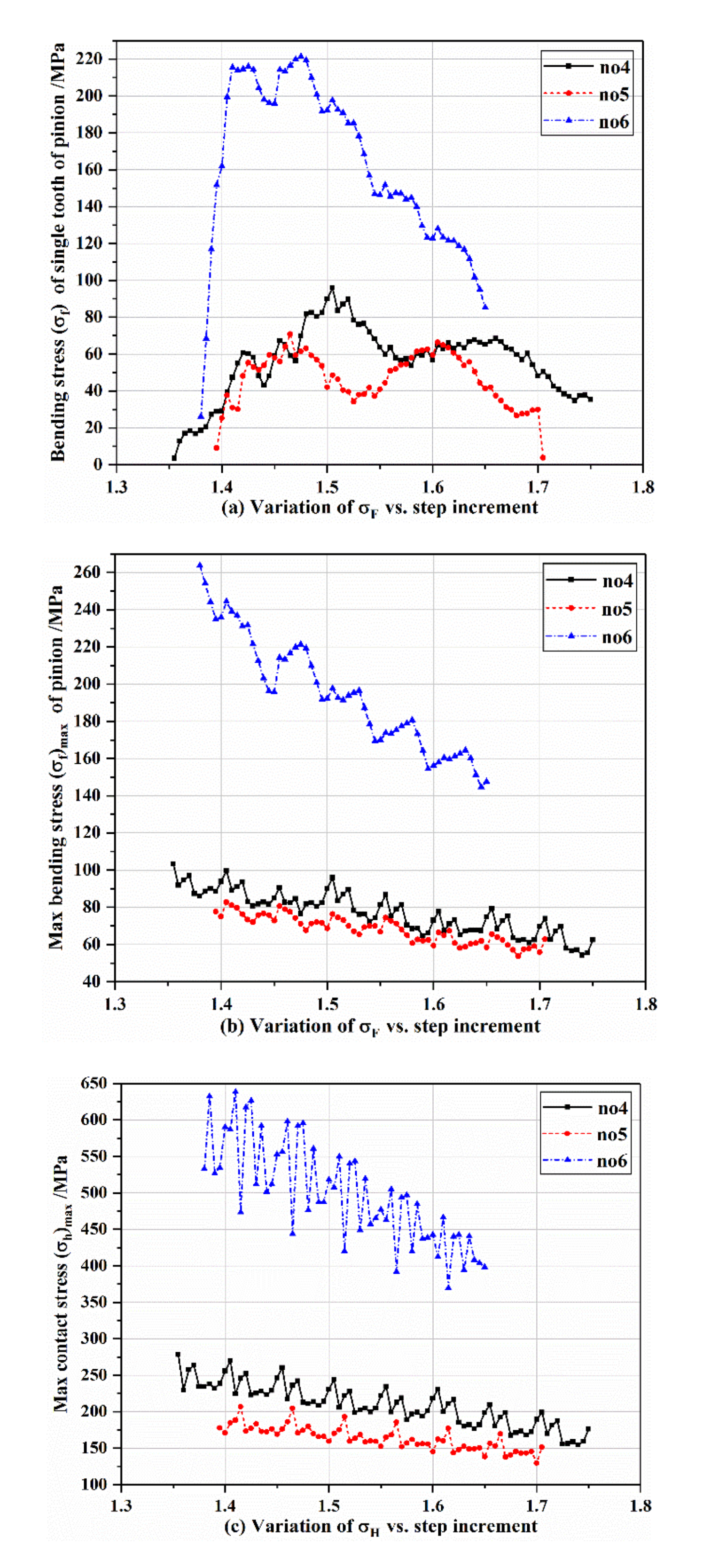
4.2. Influence of Modification Angle

The influence of modification angle on bending and contact stresses is shown in Figure 13a–c. In the complete cycle of single-tooth engagement, the maximum bending stress peaks in groups 4–6 are 96 Mpa, 66 Mpa, and 220 MPa, respectively. The stress value for the 13° deflection angle in group 5 is 31.3% lower than that of the 6° deflection angle in group 4, and the 20° deflection angle in group 6 is 129.2% higher than that of the 6° deflection angle in group 4 (Figure 13a). When multiple teeth enter the meshing state, the maximum bending stress of the first stress peaks in groups 4–6 are 105 Mpa, 85 Mpa, and 270 MPa, respectively. Group 5 is 19.0% lower than group 4 and group 6 is 157.1% higher than group 4 (Figure 13b). The maximum contact stresses of the first stress peaks in groups 4–6 are 275 Mpa, 208 Mpa, and 640mpa, respectively. The second group is 24.4% lower than the first group, and the third group is 132.7% higher than the first group (Figure 13c). As can be seen, the maximum bending and contact stresses when the modification angle is 13° are slightly smaller than those when the modification angle is 6°. However, when the modification angle increases to 20°, all maximum stresses increase rapidly. This is because the modification angle keeps the starting mesh point away from the pitch point position to avoid contact stress concentration, and also makes the bending stiffness of the pinion tooth decrease. However, the excessive modification angle leads to a remarkable decrease in contact ratio (multi-tooth meshing cycle is shortened), which can be seen from the step increments spanned by the curve in Figure 13a–c. In addition, the excessive modification angle also brings the two bending stress peaks closer together (Figure 13a).

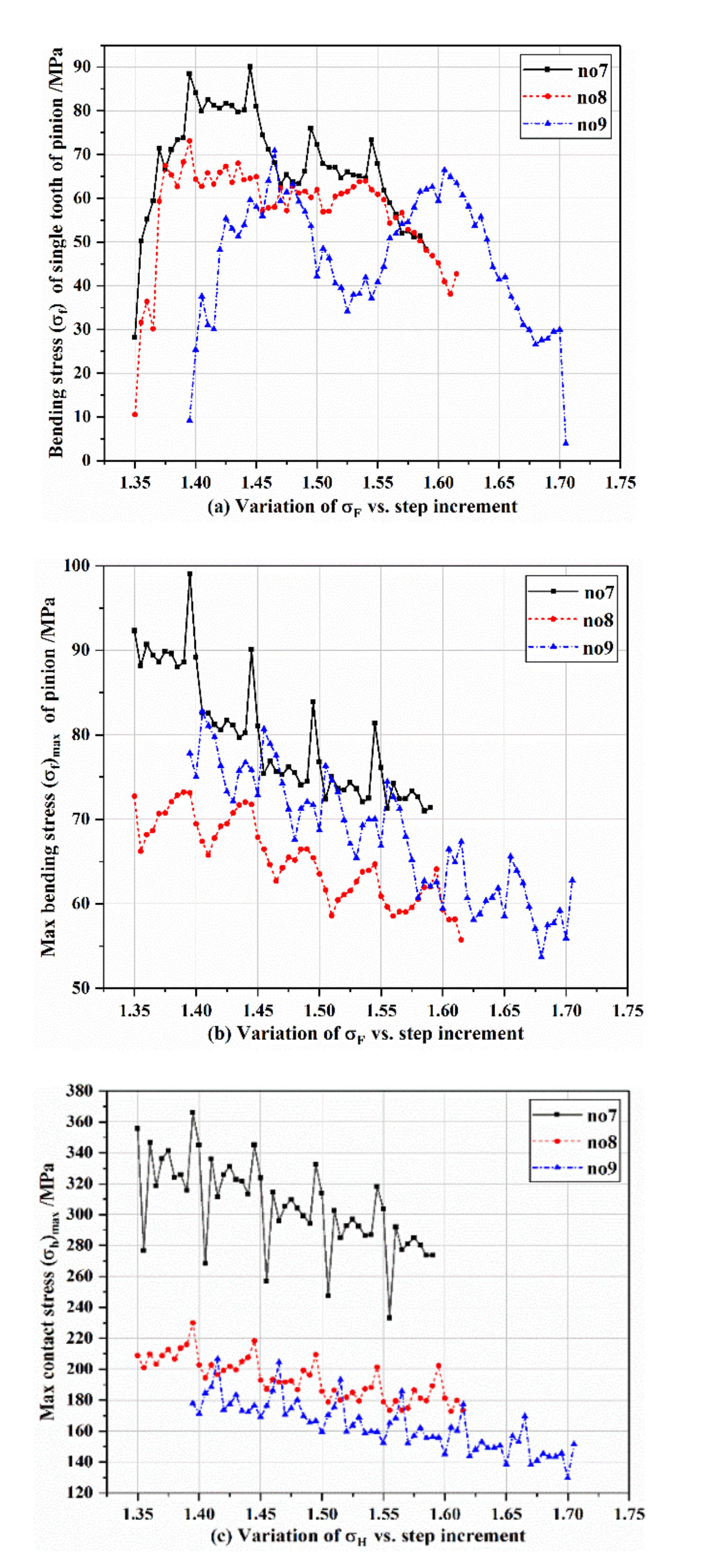
4.3. Influence of Addendum Coefficient

The influence of the addendum coefficient on bending and contact stresses is shown in Figure 14a–c. It can be observed that the contact ratio increases with addendum coefficient (the meshing coefficient increases with the increase in multi-tooth period). The maximum bending stress of a single tooth is 90 Mpa, the maximum bending stress of multi-tooth meshing is 180 MPa, and the maximum contact stress is 365 Mpa, whether for a single pinion tooth or the whole gear drive, and the bending and contact stresses both decrease significantly when the addendum coefficient is greater than 1. However, it is not the case that the larger the addendum coefficient, the smaller the stress. As shown in Figure 14a, the maximum bending stress of a single tooth when meshing out when the addendum coefficient is 1.35 is greater than that when the addendum coefficient is 1.15. As shown in Figure 14b, the maximum bending stress, σ f m a x , when the addendum coefficient is 1.35 is higher than that when the addendum coefficient is 1.15. As shown in Figure 14c, when the addendum coefficient is 1.15 and 1.35, the tooth surface contact stress decreases rapidly.
To sum up, with the increase in tooth root deflection angle, the gear bending stress and contact stress gradually decrease. With the increase in the correction angle, the period of multi-tooth meshing will gradually shorten, and when it is greater than a certain angle, the bending stress and contact stress of the gear will suddenly increase. With the increase in the addendum coefficient, the multi-tooth meshing cycle increases. When the addendum coefficient is greater than a certain value, the gear contact stress will decrease.

5. A Case of Comparative Study between HCR and Involute Internal Spur Gear Drive

For HCR internal spur gear drives, the tooth profiles are fully programmed through MATLAB and all the point coordinates on the tooth profile can be output. In order to retain the same center distance, number of teeth and gear ratio as HCR internal gear drives, the negative addendum modification is conducted and a standard module value of 2.5 is selected for the involute drive. Wire electrical discharge machining is used for gear cutting. The final processed pinion specimens are shown in Figure 15, and their specifications are shown in Table 1, Table 2 and Table 3.

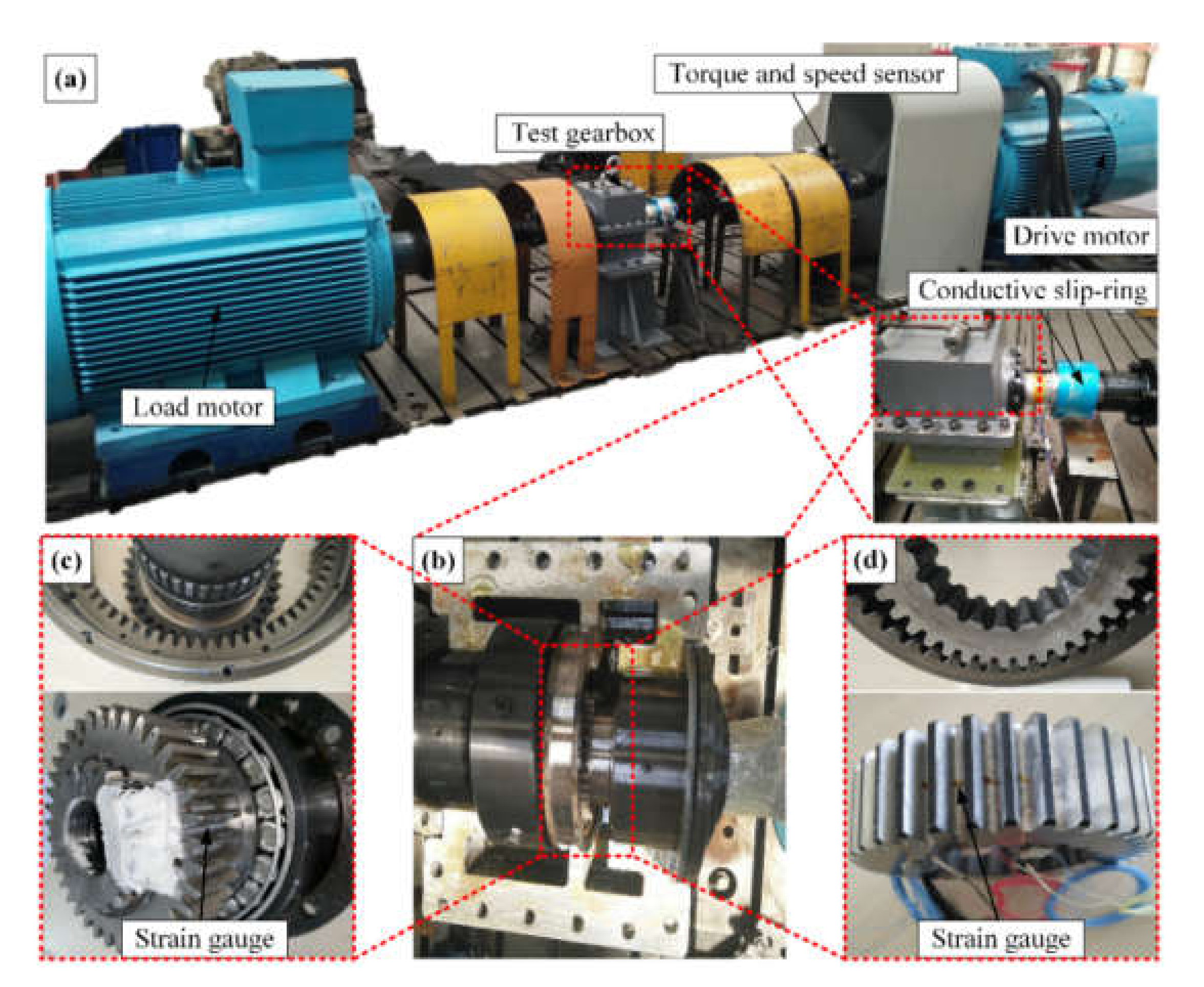
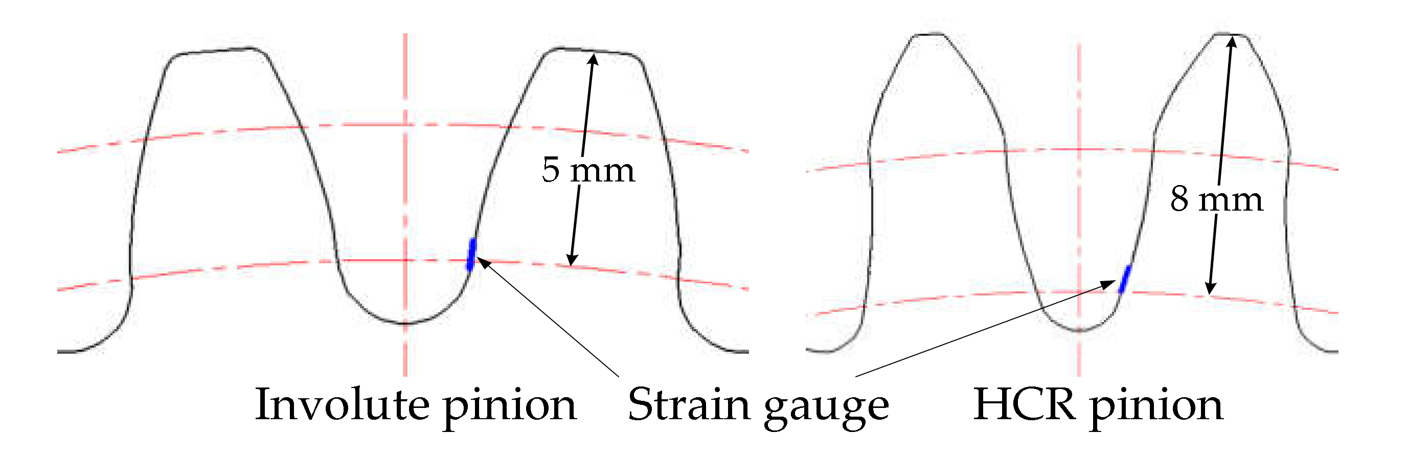
5.1. Experimental Details

The layout and composition of the test setup are shown in Figure 16, which mainly includes the gear pair to be tested, a test gearbox, conductive slip ring, drive motor, load motor, input and output couplings, torque and speed sensor, control cabinet, data acquisition system, and a computer installed with data acquisition software. The drive motor is adjusted to the set rotational speed, and the output torque of the load motor is adjusted to a specific value so that the input torque of the drive motor reaches the set value ( T input   torque ). The test procedure is a continuous process, and the conversion between working conditions is completed without stopping. To obtain a stable signal, the sampling time under each working condition is set to 2 min, and the sampling frequency is set to 10,000 Hz. Rotational speeds are 360, 420, 540, 660, and 780 r/min and input torque increases in increments of 100 Nm from 100 to 1200 Nm.
Strain gauges are attached to the adjacent bottom of tooth space for the involute pinion and HCR pinion. Every strain gauge is located on the middle of the tooth root along the tooth width, and the position in the tooth depth direction is shown in Figure 17. The filet stress is given by σ = E ε , where E represents the elastic modulus of the gear material and ε is the filet strain measured by the strain gauge.
For non-standard gear drives, the contact ratio calculation method is defined as
ε = T t o l 1 T s t a 2 T s t a 1
where ε is contact ratio, T t o l 1 is the total mesh time of gear tooth 1, T s t a 1 is the starting mesh moment of gear tooth 1, T s t a 2 is the starting mesh moment of gear tooth 2. Furthermore, gear tooth 1 and gear tooth 2 are two adjacent teeth, and gear tooth 2 enters into the mesh after gear tooth 1. The starting point and ending point of a certain gear tooth in a mesh cycle are obtained by using the strain signal denoise method based on a low-pass filter. The judgment basis is given below,
  • Starting moment in a mesh cycle: the strain value is greater than the set threshold (75 μ m / m ) and the strain value at the previous moment is less than the set threshold.
  • Ending moment in mesh cycle: the strain value is less than the set threshold (75 μ m / m ) and the strain value at the previous moment is greater than the set threshold, and the total meshing time is longer than 40 sampling points (namely 0.004 s).

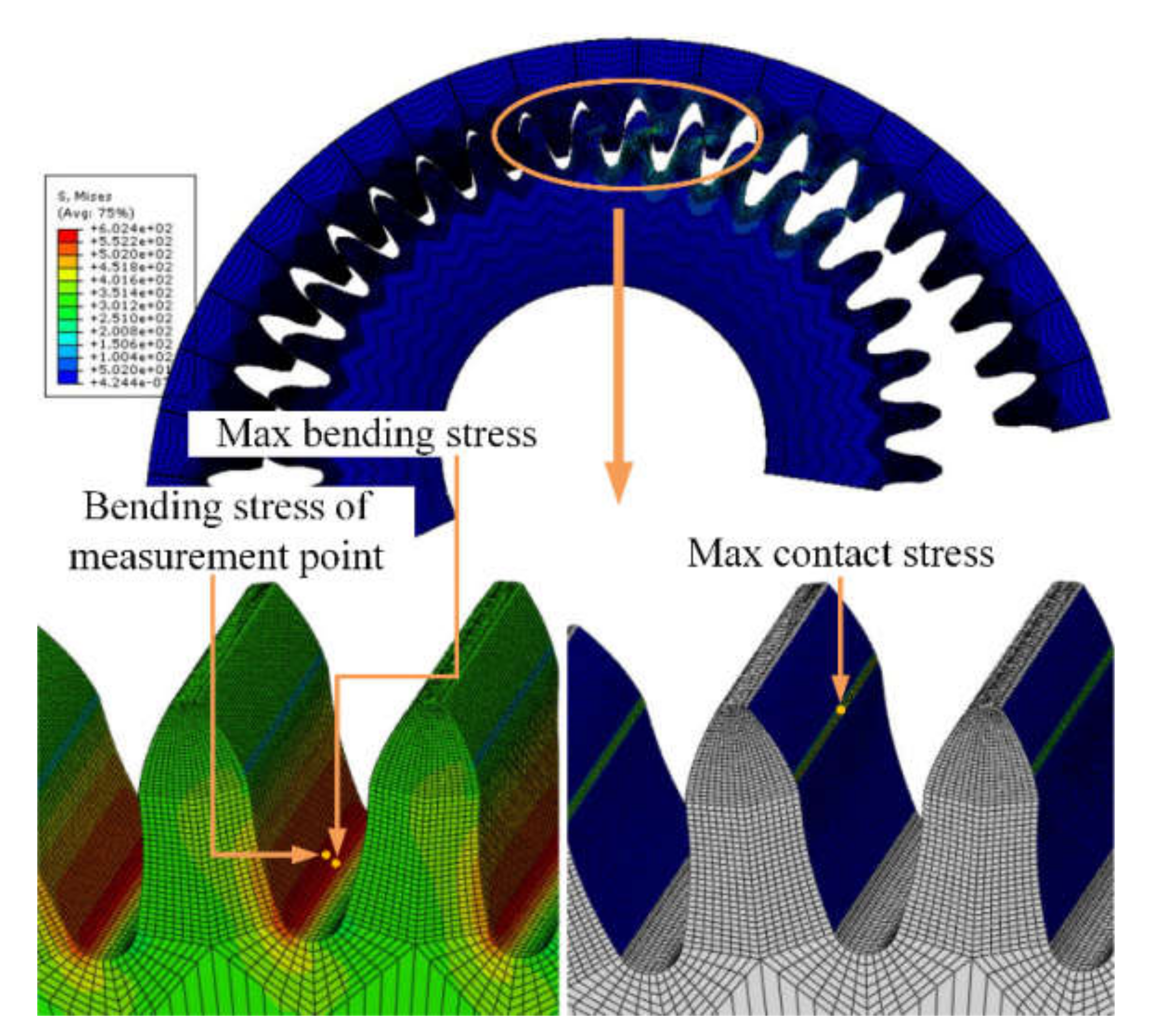
5.2. 3D Finite-Element Models Considering Multi-Pair Contact

Three-dimensional FEMs considering multi-contact tooth pairs have been established for HCR internal spur gear pairs and involute internal spur gear pairs (Figure 18) to compare them with the experimental results and investigate the surface contact stress. The contact surface of the internal gear is the master surface and the contact surface of the pinion is the slave surface. Assume that hard contact occurs between the tooth surfaces and the sliding friction coefficient is 0.1. The element type C3D8R is selected, and the rotational angular velocity at the center of the pinion and the torque at the center of internal gear are set to 56.5 rad/s (540 r/min) and 762 Nm ( 600   Nm × z 2 / z 1 ), respectively, which are the same as the working condition settings in the experiment.

6. Comparison Results and Discussions

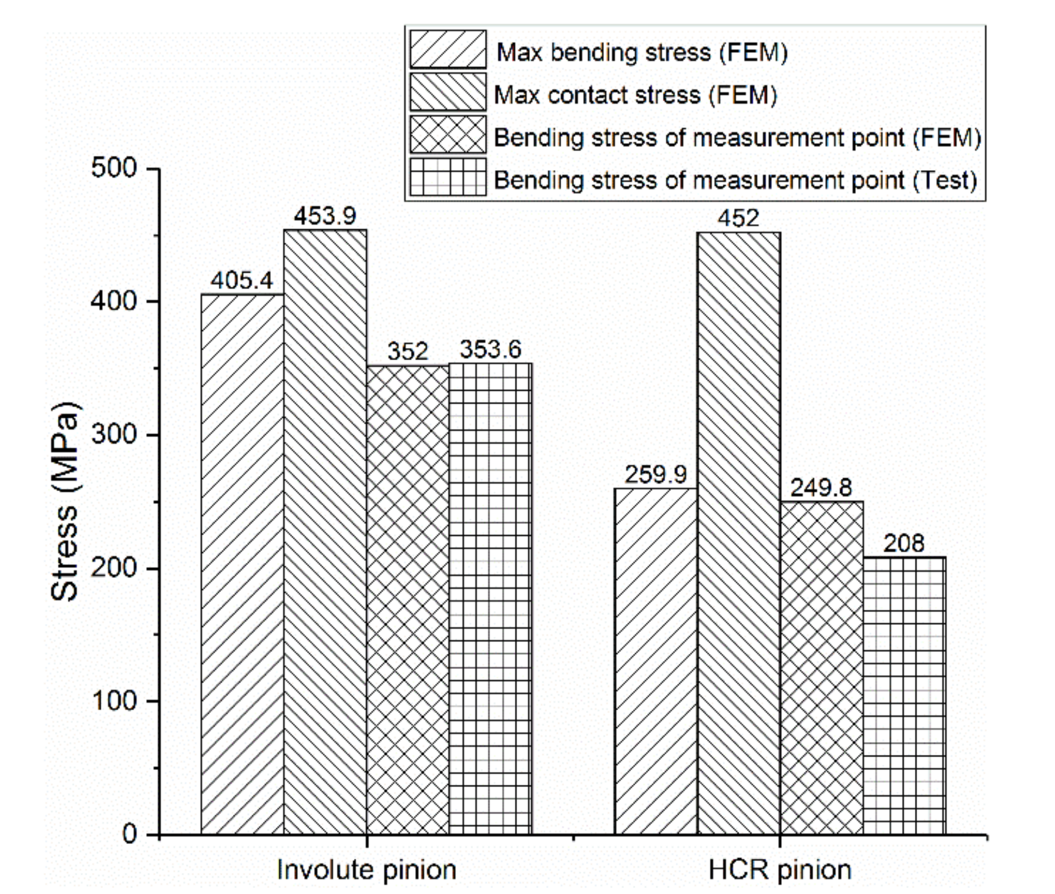
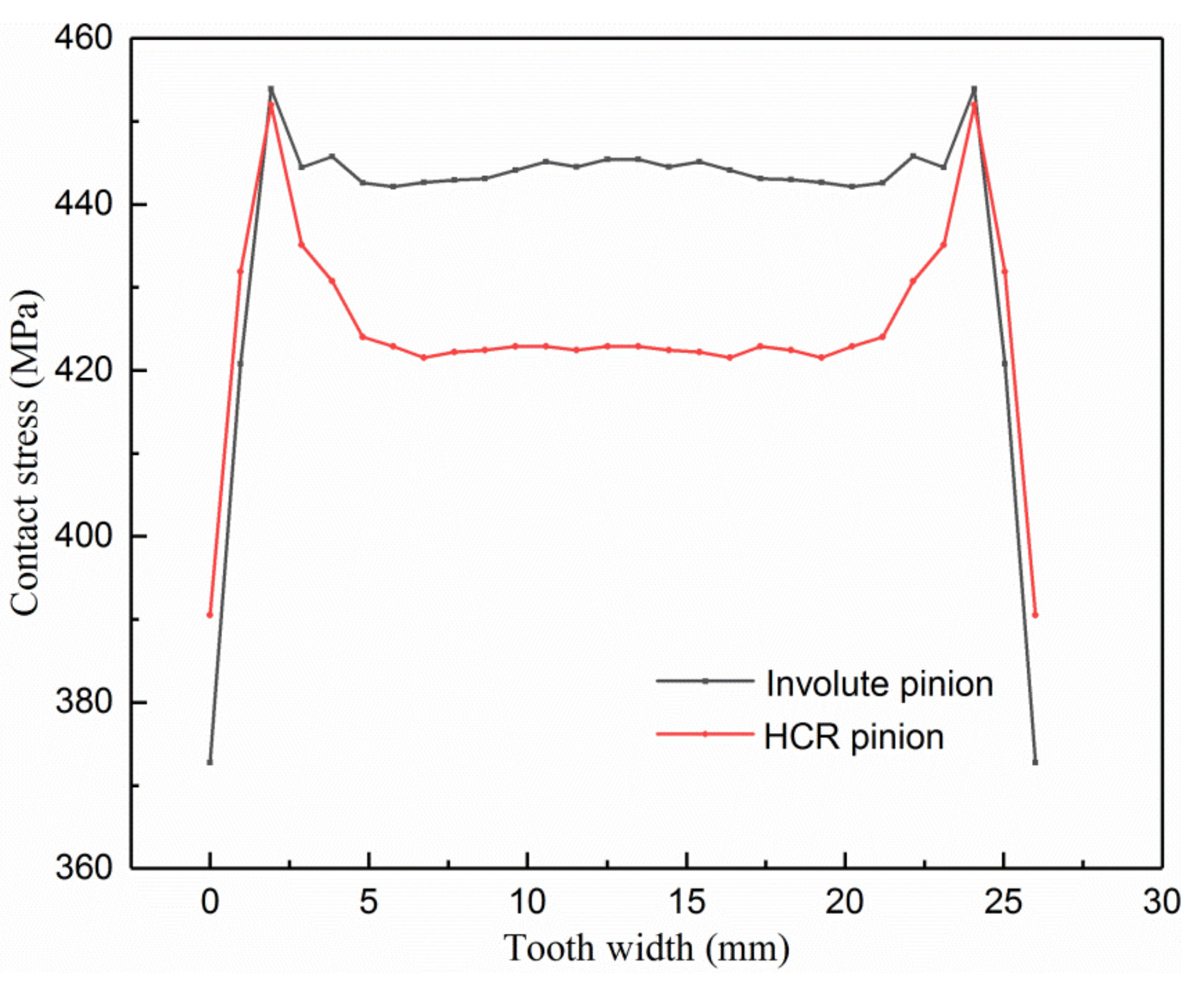
6.1. Bending Stress and Contact Stress
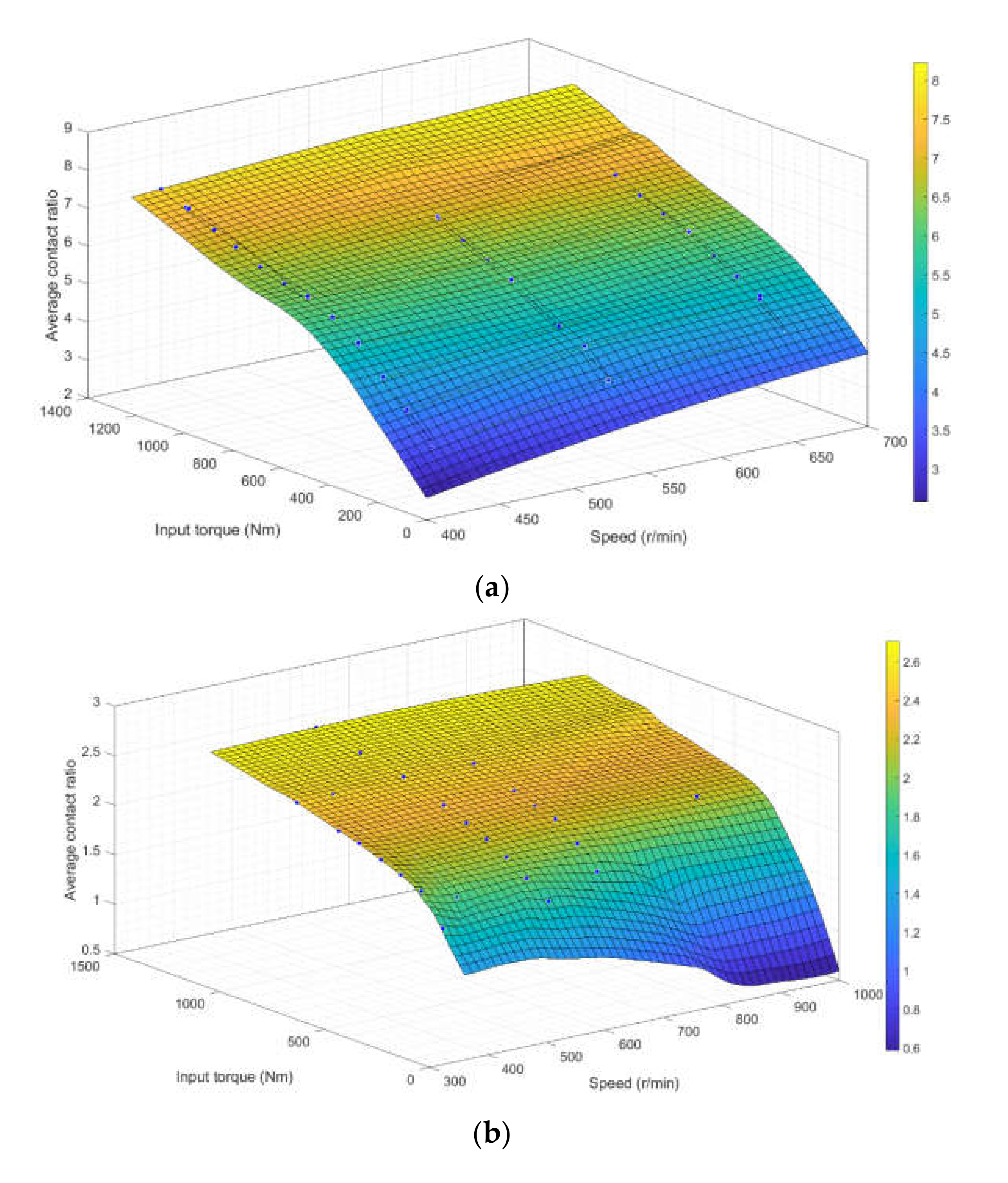
The maximum bending and contact stresses are taken from the middle position along the tooth width without considering stress concentration on the edge of the end surface. The maximum principal stress during a mesh cycle is used to evaluate the bending stress. Meanwhile, the maximum CPRESS is extracted to reveal the contact stress. As presented in Figure 19 and Figure 20, the number of gear teeth engaged in a mesh cycle of the HCR internal gear drive is significantly more than that of the involute drive. However, the contact bandwidth on the HCR pinion flank is smaller than that of the involute one. Furthermore, the maximum bending stress position is not consistent with the attachment position of the strain gauge in the experiment, which is closer to the tooth root under the strain gauge.
Figure 21 shows the comparison of maximum bending stress and contact stress of the FEA results between the involute internal spur gear pair and the HCR internal spur gear pair, as well as the comparison between the maximum average experimental values of bending stress and FEA results. It can be seen that the maximum bending stress of the HCR pinion is reduced by about 35.99% (as shown in Table 4) because of the high contact ratio compared with the involute pinion. The maximum contact stress of the tooth flanks is almost equal. The main reason for this is that the contact stress is decided by both the contact ratio and induced curvature. The HCR internal gear drive designed in Section 2 has a higher induced curvature than the involute one. Meanwhile, the contact is convex-to-convex for the HCR internal gear pair and convex-to-concave for the involute internal gear pair. Therefore, the combination of the above factors results in the small contact area and higher contact stress of the HCR internal spur gear pair.
The differences between the experimental results and FEA results are within the acceptable limits. The experimental bending stress and FEA results on the measurement point of the involute internal spur gear pair have very good consistency. However, the FEA result (249.8 Mpa) is higher compared to the experimental bending stress (208 Mpa) on the measurement point of the HCR internal spur gear pair, with a maximum percentage difference of 16.7%, which may be due to the error in the attachment position of strain gauges and the frictional effects of the gear drive in real experimental conditions. Extracting the tooth surface contact stress in the tooth-width direction of the gear, as shown in Figure 22, shows that the contact stress distribution is not completely uniform.

6.2. Contact Ratio

Considering all the effective strain samples under the test conditions, the average contact ratios of the gear pairs in one mesh cycle for every working state are solved, and the average contact ratios under various working conditions of the HCR internal spur gear drive and involute internal spur gear drive are obtained through surface fitting, as shown in Figure 23a,b.
It is clear from the experimental results that while the rotational speed has little effect on contact ratio, the input torque has a decisive influence on it. The percentage increases in the average contact ratio of the HCR gear pair compared to the involute gear pair under rotational speeds of 360 r/min and continuously varied increasing input torque are 97.14%, 108.33%, 128.17%, 151.13%, 159.57%, 166.95%, 162.4%, 174.71%, and 186.3%, as shown in Table 5. It can be seen that the contact ratios of both the involute internal spur gear pair and the HCR internal spur gear pair increase with input torque due to the large elastic deformation of the gear teeth. Moreover, the increase in contact ratio of the HCR gear pair is significantly faster than that of the involute pair. However, the actual measured contact ratio for the HCR gear pair is much smaller than the design value under light loading conditions, which may be caused by geometrical errors such as profile and pitch error. In the case of heavy loading, the deformation of gear teeth exceeds the error amount and the design tooth clearance, which leads to a significant improvement in the contact ratio. The comparison has shown that the contact ratio of the HCR gear pair exceeds 7 at input torques above 1000 Nm, but this reaches no more than 3 for the involute gear pair under the same conditions. This gap is essentially caused by differences in the tooth profile, including root bending stress under different rotational speeds and input torque conditions, as shown in the Figure 24. The tooth root stress of the involute standard gear increases with the increase in torque, as shown in Figure 24b. When the input torque is lower than 800 nm, the tooth root stress of the HCR gear increases with the increase in torque. In addition, when the input torque is higher than 800 Nm, the contact ratio increases with the increase of torque, and more teeth participate in meshing, which reduces the tooth root stress of a single tooth, as shown in Figure 24a.

7. Conclusions

In this paper, a novel HCR tooth profile with extended addendum and arc path of contact was proposed. A parametric analysis of the root deflection angle, modification angle, and addendum coefficient was performed. Experimental and FEA studies on the load capacity of HCR internal spur gear drives and involute internal spur gear drives were conducted and compared.
The present results reveal that an appropriate increase in the deflection angle and modification angle leads to reductions in bending and contact stresses. The maximum contact stress decreases with an increase in the addendum coefficient, while the maximum filet stress varies insignificantly.
Owing to the high contact ratio, the bending and contact stresses of the HCR internal spur gear pair are both reduced compared with the involute pair. However, the decrease in bending stress is obvious, while the contact stress only experience little reduction due to the high induced curvature. The experimental and FEA results are in good agreement in terms of bending stress, which increases the credibility of using FEMs to analyze contact stress. When the input torque of the HCR internal gear pair is more than 1000 Nm, the contact ratio will be more than 7, which is much higher than that of the involute pair. The maximum contact ratio of the involute gear pair does not exceed 3 under the allowable input torque. The contact ratios of the HCR and involute internal gear pairs both increase with the input torque, and the influence of the rotational speed on the contact ratio can almost be neglected.
Specifically, HCR internal gear drives are more suitable for heavy-load conditions, but good machining accuracy is essential for the tooth profile to ensure the high contact ratio and high hardness required for the tooth surface to improve the contact strength and wear resistance.

Author Contributions

Conceptualization, Y.W.; data curation, P.L.; formal analysis, P.L.; investigation, Y.W. and D.D.; methodology, P.L.; validation, D.D.; writing—original draft, P.L.; writing—review and editing, P.L. All authors have read and agreed to the published version of the manuscript.

Funding

This work was supported by the Technology Fundamental Research Funding Project of China under Grant JSZL2020208A001 and National Key R&D Program Funding Project of China under Grant 2019YFB2004400.

Institutional Review Board Statement

Not applicable.

Informed Consent Statement

Not applicable.

Data Availability Statement

Not applicable.

Conflicts of Interest

The authors declare no conflict of interest.

Nomenclature

S f :   { O f , X f , Y f }fixed coordinate system
x f , y f coordinate values of meshing point on the coordinate system S f
R radius of path of contact
θ rotational angle of radius R in the counterclockwise direction
r 1 radii of pitch circle of pinion
r 2 radii of pitch circle of internal gear
r a 1 addendum circle radii of pinion
r a 2 addendum circle radii of internal gear
γ deflection angle
φ modification angle
σ f m a x maximum bending stress
σ h m a x maximum contact stress
b tooth width
ε contact ratio
T t o l 1 total mesh time of gear tooth 1#
T s t a 1 starting mesh moment of gear tooth 1#
T s t a 2 starting mesh moment of gear tooth 2#

References

  1. Zhang, B.; Liu, H.; Zhu, C. Numerical simulation of competing mechanism between pitting and micro-pitting of a wind turbine gear considering surface roughness. Eng. Fail. Anal. 2019, 104, 1–12. [Google Scholar] [CrossRef]
  2. Wang, S.; Zhu, R.; Feng, J. Study on load sharing behavior of coupling gear-rotor-bearing system of GTF aero-engine based on multi-support of rotors. Mech. Mach. Theory 2020, 147, 103764. [Google Scholar] [CrossRef]
  3. Kostrzewski, M.; Melnik, R. Numerical Dynamics Study of a Rail Vehicle with Differential Gears. Proc. Eng. 2019, 192, 439–444. [Google Scholar] [CrossRef]
  4. Miler, D.; Hoic, M. Optimization of cylindrical gear pairs: A review. Mech. Mach. Theory 2021, 156, 104156. [Google Scholar] [CrossRef]
  5. Khabou, M.T.; Bouchaala, N.; Chaari, F. Study of a spur gear dynamic behavior in transient regime. Mech. Syst. Signal Process. 2011, 25, 30893101. [Google Scholar] [CrossRef]
  6. Buckingham, E. Analytical Mechanics of Gears; Dover Publication: New York, NY, USA, 1963. [Google Scholar]
  7. Li, S. Finite element analyses for contact strength and fillet strength of a pair of spur gears with machining errors, assembly errors and tooth modifications. Mech. Mach. Theory 2007, 42, 88–114. [Google Scholar] [CrossRef]
  8. Li, S. Effect of addendum on contact strength, fillet strength and basic performance parameters of a pair of spur gears. Mech. Mach. Theory 2008, 43, 1557–1584. [Google Scholar] [CrossRef]
  9. Sankar, S.; Nataraj, M. Profile modification—A design approach for increasing the tooth strength in spur gear. Int. J. Adv. Manuf. Technol. 2011, 55, 1–10. [Google Scholar] [CrossRef]
  10. Maper, A.; Karu, S.; Patil, S. Analysis and formulation of spur gear stresses with different tip modifications. J. Cent. South Univ. 2019, 26, 2368–2378. [Google Scholar] [CrossRef]
  11. Dong, P.; Zuo, S.; Du, S. Optimum design of the tooth root profile for improving fillet capacity. Mech. Mach. Theory 2020, 151, 103910. [Google Scholar] [CrossRef]
  12. Sánchez, M.; Pleg, M.; Ped, J. Influence of profile modifications on meshing stiffness, load sharing, and transmission error of involute spur gears. Mech. Mach. Theory 2019, 139, 506–525. [Google Scholar] [CrossRef]
  13. Nguyen, T. Compact design of high-contact-ratio spur gears. In Proceedings of the ASME 2020. International Mechanical Engineering Congress and Exposition, IMECE2020, Portland, OR, USA, 16–19 November 2020. [Google Scholar]
  14. Lin, H.; Lee, C.; Oswald, F. Computer-aided design of high-contact-ratio gears for minimum dynamic load and stress. ASME J. Mech. Des. 1993, 115, 171–178. [Google Scholar] [CrossRef]
  15. Kape, A. Geometry and design of involute spur gears with asymmetric teeth. Mech. Mach. Theory 2000, 35, 117–130. [Google Scholar]
  16. Mar, P.; Muth, G. Investigation of load carrying capacity of asymmetric high contact ratio spur gear based on load sharing using direct gear design approach. Mech. Mach. Theory 2016, 96, 52–74. [Google Scholar]
  17. Muni, D.; Muth, G. A comprehensive study on the asymmetric internal spur gear drives through direct and conventional gear design. Mech. Based Des. Struct. Mach. 2009, 37, 431–461. [Google Scholar] [CrossRef]
  18. Yildirim, N.; Munro, R. A systematic approach to profile relief design of low and high contact ratio spur gears. Part C J. Mech. Eng. Sci. 1999, 213, 551–562. [Google Scholar] [CrossRef]
  19. Elkholy, A. Tooth load sharing in high-contact ratio spur gears. J. Mech. Trans. Autom. 1985, 107, 11–16. [Google Scholar] [CrossRef]
  20. Ravivarman, R.; Pal, K.; Pra, S.R. Evolution of balanced root stress and tribological properties in high contact ratio spur gear drive. Mech. Mach. Theory 2018, 126, 491–513. [Google Scholar] [CrossRef]
  21. Sánchez, M.; Ped, J.; Ple, M. Contact stress calculation of high transverse contact ratio spur and helical gear teeth. Mech. Mach. Theory 2013, 64, 93–110. [Google Scholar] [CrossRef]
  22. Mar, P.; Muth, G. Effect of drive side contact ratio on direct design asymmetric high contact ratio spur gear based on load sharing. Appl. Mech. Mater. 2014, 592, 2292–2296. [Google Scholar]
  23. Wang, Y.; Ren, S.Y.; Li, Y. Design and manufacturing of a novel high contact ratio internal gear with a circular arc contact path. Int. J. Mech. Sci. 2019, 153, 143–153. [Google Scholar] [CrossRef]
  24. Wang, Y.; Dou, D.; Shiyuan, E.; Wang, J. Comparison on torsional mesh stiffness and contact ratio of involute internal gear and high contact ratio internal gear. Proc. Inst. Mech. Eng. Part C J. Mech. Eng. Sci. 2020, 234, 1423–1437. [Google Scholar] [CrossRef]
  25. Zhang, J.; Wang, T. Fuzzy reliability optimization design of double circular arc gear transmission. Mech. Eng. Auto. 2001, 2, 14–16. [Google Scholar]
  26. Hu, G.; Shao, J.; Cheng, Y. Double objective optimization design of double circular arc gear. Mod. Mach. 2020, 4, 7–12. [Google Scholar] [CrossRef]
  27. Zhao, L. Study on parametric design and mechanical performance properties of pure rolling single arc gear. Ph.D. Thesis, Nanjing Forestry University, Nanjing, China, December 2019. [Google Scholar] [CrossRef]
  28. Zhang, J. Finite Element Analysis and Optimization Design of Tooth Profile Parameters of Double Circular Arc Gear; Taiyuan; University of Technology: Taiyuan, China, 2002. [Google Scholar]
  29. Zhang, J.; Wang, T. Fuzzy optimization of tooth profile parameters of double circular arc gear. J. Tai. Univ. Tech. 2002, 33, 118–120. [Google Scholar]
  30. Guo, H.; Zhao, N.; Zhang, S. Optimization analysis of tooth root strength of double circular arc gear based on function approximation. Mech. Des. 2007, 24, 14–16. [Google Scholar]
  31. Jiao, H. Optimal Design and Finite Element Analysis of Double Circular Arc Gear Transmission. Master’s Thesis, Northeastern University, Shenyang, China, 2008. [Google Scholar]
  32. Zhao, P. Finite Element Analysis of Meshing Characteristics and Stress of Double Circular Arc Gear Based on GA; Lanzhou University of Technology: Lanzhou, China, 2008. [Google Scholar]
  33. Qian, X.; Wu, Z. Multi objective robust optimization design of double circular arc gear transmission. Mech. Trans. 2010, 34, 45–48. [Google Scholar]
  34. Lu, J.; Litvin, F.L.; Chen, J.S. Load Share and Finite Element Stress Analysis for Double Circular-Arc Helical Gears. Math. Comput. Model. 1995, 21, 31–47. [Google Scholar] [CrossRef]
  35. Qu, W.; Shen, Y.; Xu, J. Finite element analysis of contact stress of double circular arc gear based on ANSYS. J. Agric. Mach. 2006, 37, 139–141. [Google Scholar]
  36. Qu, W. Research on Working Capacity of Double Circular Arc Gear Transmission under Unconventional Conditions; Xi’an University of Science and Technology: Xi’an, China, 2006. [Google Scholar]
  37. Ren, Z.Y. Static finite element analysis of double circular arc and four circular arc gears based on ANSYS. Mach. Too. Hyd. 2009, 37, 213–214. [Google Scholar]
  38. Jiang, G.; Wang, S.; Mei, X. Directional conjugate design method of double circular arc tooth profile of harmonic gear drive. J. Xi’an Jiaotong Univ. 2019, 53, 8–14. [Google Scholar]
  39. Zhang, Y.; Wang, T.; Zhao, L. Strength and fatigue analysis of double circular arc planetary gear transmission system. Mech. Trans. 2021, 45, 135–140. [Google Scholar] [CrossRef]
Figure 1. Hob and tip contour replaced by the Bezier curve.
Applsci 12 03345 g001
Figure 2. Finite-element model with boundary conditions for MPCM.
Applsci 12 03345 g002
Figure 3. Area of existence diagram for constant drive-side contact ratio.
Applsci 12 03345 g003
Figure 4. The main process of this paper.
Applsci 12 03345 g004
Figure 5. The flow chart of the design method for HCR internal spur gear drive.
Applsci 12 03345 g005
Figure 6. Path of contact of HCR internal spur gear drive: (a) global contact path; (b) enlarged contact path.
Applsci 12 03345 g006
Figure 7. HCR gear tooth profile before and after root modification: (a) Unmodified gear profile. (b) Tooth root modification profile of pinion ① and internal gear ②.
Applsci 12 03345 g007
Figure 8. HCR gear tooth top-modification process. (a) Defined addendum modification parameters. (b) Cusp transition treatment at the connection between tooth top and tooth root profile modification: ① Cusp modification of pinion. ② Internal gear tip modification. (c) The tooth profile after tooth crest and root modification of pinion and internal gear with smooth cusp transition.
Applsci 12 03345 g008
Figure 9. Two-dimensional 20-teeth finite-element model.
Applsci 12 03345 g009
Figure 10. Different tooth profiles of HCR pinion for parametric study.
Applsci 12 03345 g010
Figure 11. Results of 2D FEM: (a) maximum principal stress; (b) von Mises stress.
Applsci 12 03345 g011
Figure 12. Influence of deflection angle on bending and contact stresses. (a) Bending stress of single tooth of pinion. (b) Maximum bending stress of pinion. (c) Maximum contact stress of pinion.
Applsci 12 03345 g012
Figure 13. Influence of modification angle on bending and contact stresses. (a) Bending stress of single tooth of pinion; (b) maximum bending stress of pinion; (c) maximum contact stress of pinion.
Applsci 12 03345 g013
Figure 14. Influence of addendum coefficient on bending and contact stresses. (a) Bending stress of single tooth of pinion; (b) maximum bending stress of pinion; (c) maximum contact stress of pinion.
Applsci 12 03345 g014
Figure 15. Test gear dive: (a) HCR pinion; (b) involute pinion.
Applsci 12 03345 g015
Figure 16. Main test setup: (a) transmission system; (b) gearbox assembly; (c) HCR internal spur gear drive attached by strain gauges; (d) involute internal spur gear drive attached by strain gauges.
Applsci 12 03345 g016
Figure 17. Schematic diagram of strain gauge attachment.
Applsci 12 03345 g017
Figure 18. Schematic of the FEMs: (a) HCR internal spur gear pair, and (b) involute internal spur gear pair.
Applsci 12 03345 g018
Figure 19. Bending and contact stress results of HCR internal spur gear pair at 540 r/min and 600 Nm.
Applsci 12 03345 g019
Figure 20. Bending and contact stress results of involute internal spur gear pair at 540 r/min and 600 Nm.
Applsci 12 03345 g020
Figure 21. Comparison of bending and contact stress between involute and HCR internal gear pairs.
Applsci 12 03345 g021
Figure 22. Contact stress curve of tooth surface in the direction of tooth width.
Applsci 12 03345 g022
Figure 23. Average contact ratio under different rotational speeds and input torque conditions: (a) HCR internal spur gear drive; (b) involute internal spur gear drive.
Applsci 12 03345 g023
Figure 24. Root bending stress under different rotational speeds and input torque conditions: (a) HCR internal spur gear drive; (b) involute internal spur gear drive.
Applsci 12 03345 g024
Table 1. Design and modification parameters of HCR internal spur gear drive.
ParameterValue
Nominal module (m1/mm)2.592
Pinion tooth number (z1)37
Internal gear tooth number (z2)47
Center distance (a/mm)12.96
Filet   radius   ( r fp /mm)0.5
Tooth width (b/mm)26
Addendum coefficientvariable
Deflection angle  (γ/°)variable
Modification angle  (φ/°)variable
Material20CrNiMo
Table 2. Variable of parametric study for HCR gear drive.
Deflection Angle (°)Modification Angle (°)Addendum Coefficient
no1−4131.35
no2−6131.35
no3−8131.35
no4−661.35
no5−6131.35
no6−6201.35
no7−6131
no8−6131.15
no9−6131.35
Table 3. Design parameters for involute internal spur gear drive.
ParameterValue
Module (m2/mm)2.5
Pinion tooth number (z3)37
Internal gear tooth number (z4)47
Pressure angle  (α/°)20°
Addendum   coefficient   ( h a * )1
Addendum modification coefficient (x)−0.3
Tooth width (b/mm)26
Center distance (a/mm)12.96
Material20CrNiMo
Table 4. Percentage decrease of stress between involute and HCR internal gear pair.
Comparison ItemsInvoluteHCR% Decrease
maximum bending stress
(FEM)
405.4259.535.99%
maximum contact stress
(FEM)
453.94520.42%
bending stress of measurement point
(FEM)
352249.829.03%
bending stress of measurement point
(TEST)
353.620841.18%
% decrease between FEM and TEST−0.45%16.73%
Table 5. Percentage increase in contact ratio.
Input Torque (Nm)Contact Ratio% Increase
InvoluteHCR
1001.753.4597.14
2002.044.25108.33
3002.134.86128.17
4002.215.55151.13
5002.35.97159.57
6002.366.3166.95
8002.56.56162.4
10002.617.17174.71
12002.77.73186.3
Publisher’s Note: MDPI stays neutral with regard to jurisdictional claims in published maps and institutional affiliations.

