Article

Study on Filling Capacity of Optical Glass in a Novel Rapid Hot Embossing Process

Shenzhen Key Laboratory of High Performance Nontraditional Manufacturing, College of Mechatronics and Control Engineering, Shenzhen University, Shenzhen 518060, China
*
Author to whom correspondence should be addressed.
Appl. Sci. 2022, 12(7), 3404; https://doi.org/10.3390/app12073404
Submission received: 14 February 2022 / Revised: 24 March 2022 / Accepted: 25 March 2022 / Published: 27 March 2022

Abstract

:
This paper aims to present a novel rapid hot embossing approach and to study filling capacity of optical glass in the hot embossing process. Firstly, a novel rapid hot embossing device is developed, which consists of a rapid heating module and a precision loading module. Particularly, the rapid heating module allows a maximum temperature of 800 °C and a heating rate of 300 °C/min, with decent temperature control accuracy and uniform temperature distribution. In hot embossing process, by incompletely filling the microhole of silicon carbide mold, a microlens would be formed on the surface of glass disc, and the filling capacity of glass is quantified by the maximum height of the microlens. The tailor-made hot embossing device was exploited to conduct a series of experiments for evaluating effects of process parameters on the filling capacity of N-BK7 glass. Experimental results indicate that the filling capacity of glass could be enhanced by increasing the embossing force, the embossing temperature, the soaking time but decreasing the annealing rate. Furthermore, compared to soaking time and annealing rate, embossing force and embossing temperature have more significant influence on the filling capacity of N-BK7 glass. Therefore, the novel rapid hot embossing is a practical and promising technology for fabricating microstructures on glass materials with high softening points.

1. Introduction

Hot embossing is a well-established technology for transferring micro/nano structures from a master mold onto a polymer or glass substrate, which has advantages of high replication fidelity, high-efficiency, low-cost and flexible process modification. Therefore, it has been widely used in the fabrication of various optical components (e.g., microlens arrays [1], raster lens arrays [2], Fresnel lenses [3], and anti-reflection films [4]), micro-electro-mechanical-systems (MEMS) [5,6], biomedical products [7], and so on. As a result, over the past several years, many scholars conducted researches related to hot embossing technology, such as deformation behavior of glass [8], material modeling [9], and process optimization [10].
It is found that hot embossing processes assisted by the ultrasonic vibration [11,12], the gas [13], and the rubber pad [14] allow enhancement of the replication performance. However, these modified hot embossing approaches require complicated apparatus and high cost. Some simplified and low-cost hot embossing devices were developed and their usability had been demonstrated [6,15]. However, they were only applicable to forming low-Tg materials, due to the limitation of heating performance and the lack of inert atmosphere.
When hot embossing of high-Tg amorphous materials, like optical glass, the preform needs to be heated up to a temperature over its transition temperature, usually higher than 500 °C, so that it could be deformed under certain compression force during the molding stage. Electrical cartridge tubes heating [16] and infrared heating [17] are commonly used methods to achieve high temperature for glass hot embossing. However, they exhibit shortages of high energy consumption and long thermal cycle time, which limit the throughput. Therefore, it is non-trivial to develop a rapid hot embossing device for forming optical glass with high cost-efficiency and loading accuracy.
This study aims to propose a novel configuration of hot embossing device, which consists of a rapid heating module and a precision loading module. By using the novel rapid hot embossing device, effects of process parameters (i.e., embossing force, embossing temperature, soaking time and annealing rate) on the filling behavior of N-BK7 glass in a microhole of silicon carbide mold are evaluated. The research findings can provide useful information for selection of appropriate process parameters for glass hot embossing with equivalent loading and heating methods.

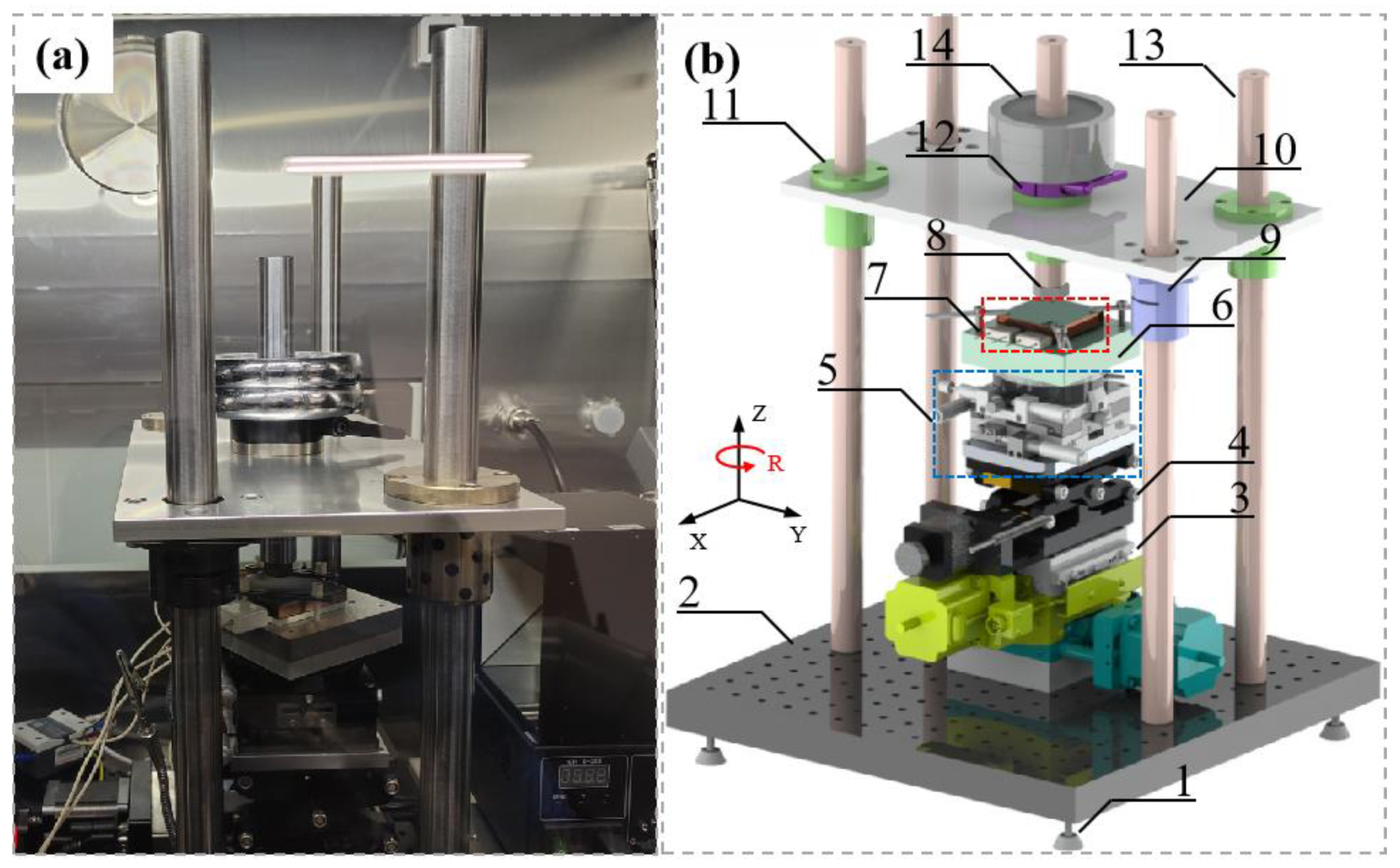
2. Development of the Novel Rapid Hot Embossing Tool

The novel rapid hot embossing device is mounted on an optical bench inside a glove box which can provide vacuum or inert gas environment, in order to protect the parts from oxidation at elevated temperatures. Figure 1a shows the assembly of the hot embossing device, which mainly consists of a precision loading module and a rapid heating module.

2.1. Precision Loading Module

The precision loading module is mainly composed by an optical table, four guiding columns, a mounted plate, a spherical indenter, a XY tilting stage, a motorized vertical stage and a XYR positioning stage. The guiding columns and mounted plate are jointed together with linear bearings and fixed collars, in order to position the mounted plate. The spherical indenter is mounted on the bottom of a shaft which can move vertically through the linear bearing at the center of the mounted plate. Weights are added on the locking ring which is clamped with the shaft. The XY tilting stage and XYR stage enable precision positioning of glass preform in five freedoms. A mica plate is inserted between the XYR stage and the rapid heating module for blocking heat transfer. The whole device can be coarsely leveled by adjusting the nuts of leveling feet of the optical table.
In the molding step, the motorized vertical stage moves upward, rendering the mold pin to contact with the spherical indenter, so that the gravitational forces of spherical indenter, shaft, locking ring and weights are applied to the glass preform. In transferring step, the motorized vertical stage moves downward until the mold pin and spherical indenter separate from each other. Since the downward movement of shaft and locking ring is constrained by the flange of the linear bearing at the center of the mounted plate, the embossing force are completely removed. Furthermore, the embossing force can be precisely tuned by changing weights. Compared to traditional loading methods, this gravity assisted loading method is simple but precise.

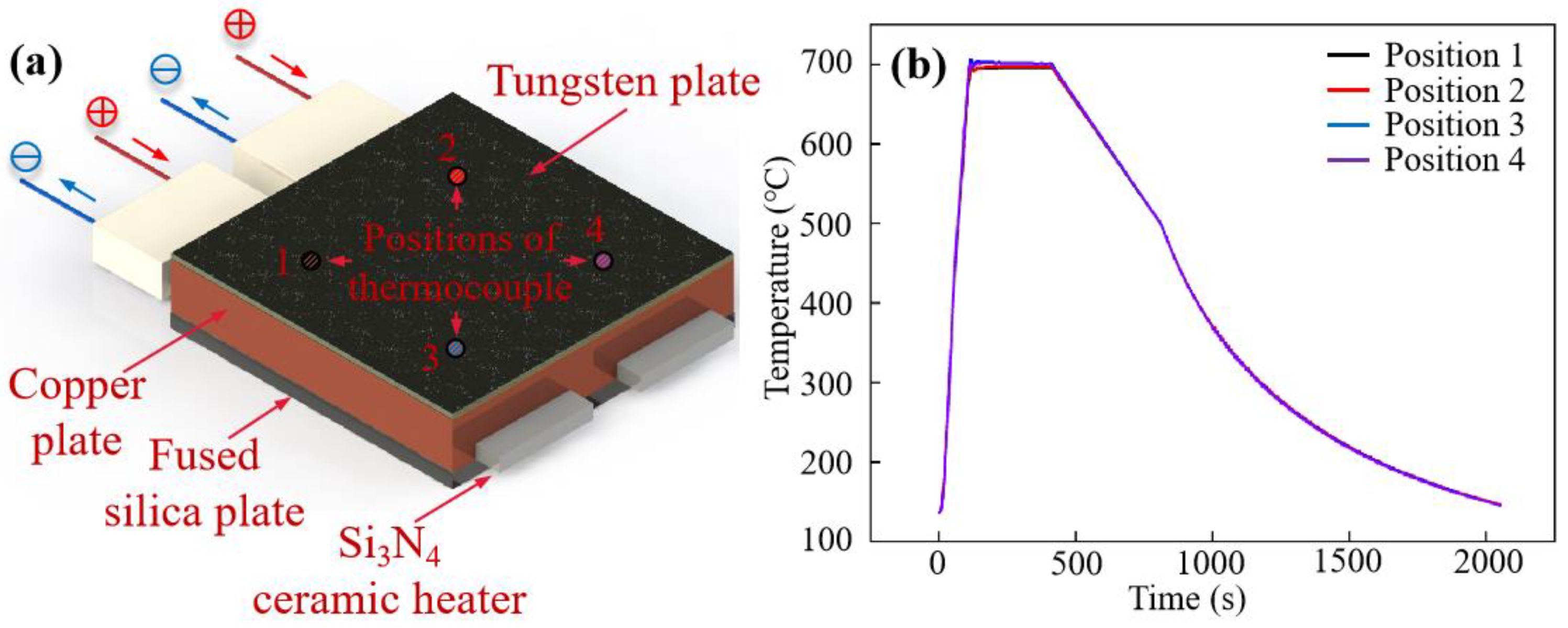
2.2. Rapid Heating Module

The silicon nitride ceramic heater is selected as heat source of the rapid heating module, due to its excellent high-temperature oxidation resistance, high durability, and rapid heating rate. However, the high-temperature heating zone is located in the central area of the ceramic heater, causing the non-uniform distribution of surface temperature. Therefore, it is inadvisable to directly use ceramic heater for hot embossing. Instead, a rapid heating module comprising a fused silica, two ceramic heaters, a copper plate and a tungsten plate is designed, as seen in Figure 2a. It is seen that the ceramic heaters are inserted into the copper plate. By exposing one side of the ceramic heater, the size of heating module is reduced. The decreased thermal mass allows the improvement of heating efficiency. Due to the considerably high thermal conductivity of copper, heat can be quickly transferred from the ceramic heaters to the copper plate via conduction, and eventually a uniform temperature distribution is obtained on the surface of copper part. On the other hand, the fused silica plate having extremely low thermal conductivity is placed below the copper plate for thermal insulation and reduction of heat loss. As the mechanical strength of copper decreases notably at elevated temperatures, the copper plate is readily warped under concentrated pressure in hot embossing. To overcome this problem, the copper plate is covered by a tungsten plate.
In the heating test, four K-type thermocouples were inserted into four holes of the copper plate, and the temperature signals were recorded by a data logger. It is evident from Figure 2b that the thermal profiles of the four positions are nearly the same, and the maximum temperature difference is about 3 °C. Moreover, the rapid heating module can reach a heating rate of 300 °C/min.

3. Materials and Methods

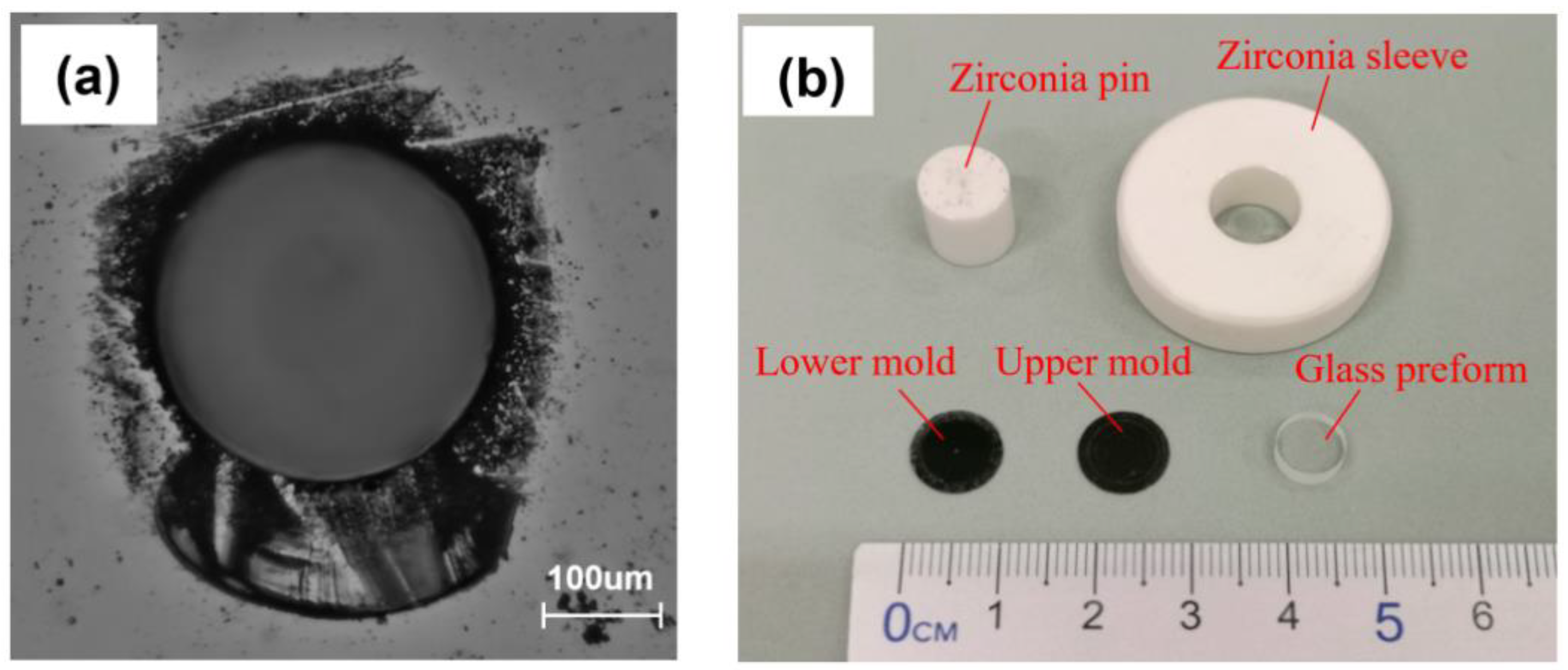
3.1. Glass, Mold and the Mold Kit

The SCHOTT N-BK7 glass is one of the most commonly used materials for fabrication of optical components, due to its superior optical properties (e.g., high Abbe number and high optical transmittance), and was thus selected as preform material in this hot embossing study. The raw N-BK7 glass blanks were purchased from SCHOTT AG. After several mechanical processing procedures, they had a diameter of 7.5 ± 0.01 mm, a thickness of 3 ± 0.01 mm and a flatness of less than 0.1 μm. Furthermore, their top and bottom surfaces were mechanically polished to have a root-mean-square (RMS) surface roughness of about 1 nm.
Silicon carbide (SiC) crystal shows high mechanical strength, relatively low coefficient of thermal expansion, and extremely low glass adhesion. As a result, polished 4H-N mono-crystalline SiC discs with a diameter of ~10 mm and a thickness of 0.35 mm were used as molds. Furthermore, a through-hole with a diameter of ~300 μm was fabricated at the center of SiC molds by laser drilling technology, with cracks generated at the edge, as seen in Figure 3a.
In presetting stage, it is hard for the manually placed glass preform and SiC molds to accurately share the same axes, and thus resulting in the misalignment. The misalignment between the glass preform and molds leads to uneven distribution of pressure during the hot embossing process, and thus deteriorates the quality of embossed glass product. To solve this problem, a mold kit is designed, which consists of a zirconia sleeve and a zirconia pin (see Figure 3b). The zirconia sleeve and pin that were fabricated by grinding and lapping are used for the positioning of glass and molds. The sleeve has an inner diameter of 10 ± 0.001 mm, an external diameter of 30 mm and a height of 10 mm, and the pin has a diameter of 9.96 ± 0.001 mm and a height of 10 mm. The small tolerance of the sleeve and pin enable a fine alignment of glass preform and molds. Moreover, zirconia exhibits high resistance to wear and oxidation at high temperatures, which is responsible for the excellent performance of the mold kit in this study.

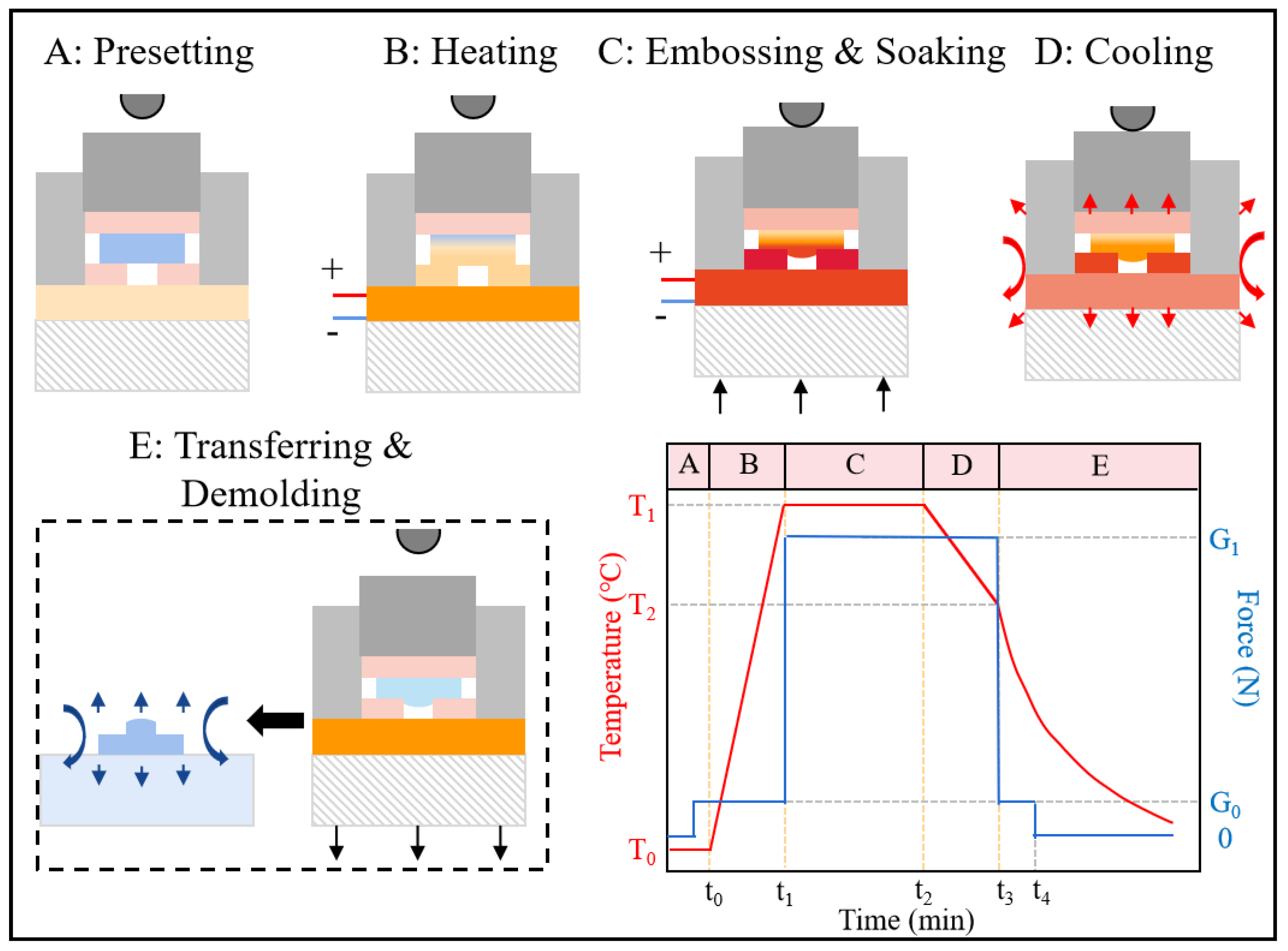
3.2. The Hot Embossing Process

The hot embossing process includes seven steps, namely, presetting, heating, embossing, soaking, cooling, transferring, and demolding (see Figure 4). In order to protect all parts from oxidization, the glove box was sealed and filled with argon gas before experiments.
At the beginning of the hot embossing process, the zirconia sleeve, lower mold, glass disc, upper mold, and zirconia pin were put in place. It is noted that the summation of gravitational force of upper mold and zirconia pin was G0. In heating step, a direct current was applied to the rapid heating module for electric heating. The rapid heating module was heated from room temperature of T0 to a target temperature of T1 at a given rate. When the temperature of the copper plate reach T1, the motorized vertical stage moved up until the gravitational forces of the spherical indenter, shaft, locking ring and weights were applied to the zirconia pin. After that, there was a soaking step which lasts a time period of t12. In the next step, the rapid heating module began to cool from T1 to T2 at a certain rate, where T2 was roughly the strain point of N-BK7 glass, that is 511 °C. As soon as the temperature was decreased to T2, the power supply for the rapid heating module was cut off. Meanwhile, the motorized vertical stage moved downward for separating the zirconia pin from the spherical indenter. When the rapid heating module cooled down to 300 °C, the mold kit was then transferred to an aluminum pad with room temperature for fast cooling. Finally, the N-BK7 glass disc was manually demolded from the mold kit for surface characterization.

3.3. Experimental Scheme

The effect of process parameters on the filling capacity of N-BK7 glass was investigated by using a parametric study. On the basis of literature review [18,19] and pilot experiments, this study concerns four process parameters, including embossing temperature, soaking time, annealing rate, and embossing force provided by weights, and each factor has 5 levels. The level values of process parameters are listed in Table 1, where experiment number 3 is the controlled trial. Experiments 1–5, Experiments 3, 6–9, Experiments 3, 10–13, and Experiments 3, 14–17 are used to investigate the effects of embossing force, embossing temperature, soaking time, and annealing rate, respectively. In addition, repeating tests were carried out under the condition 3, in order to examine the reliability of the experimental results.

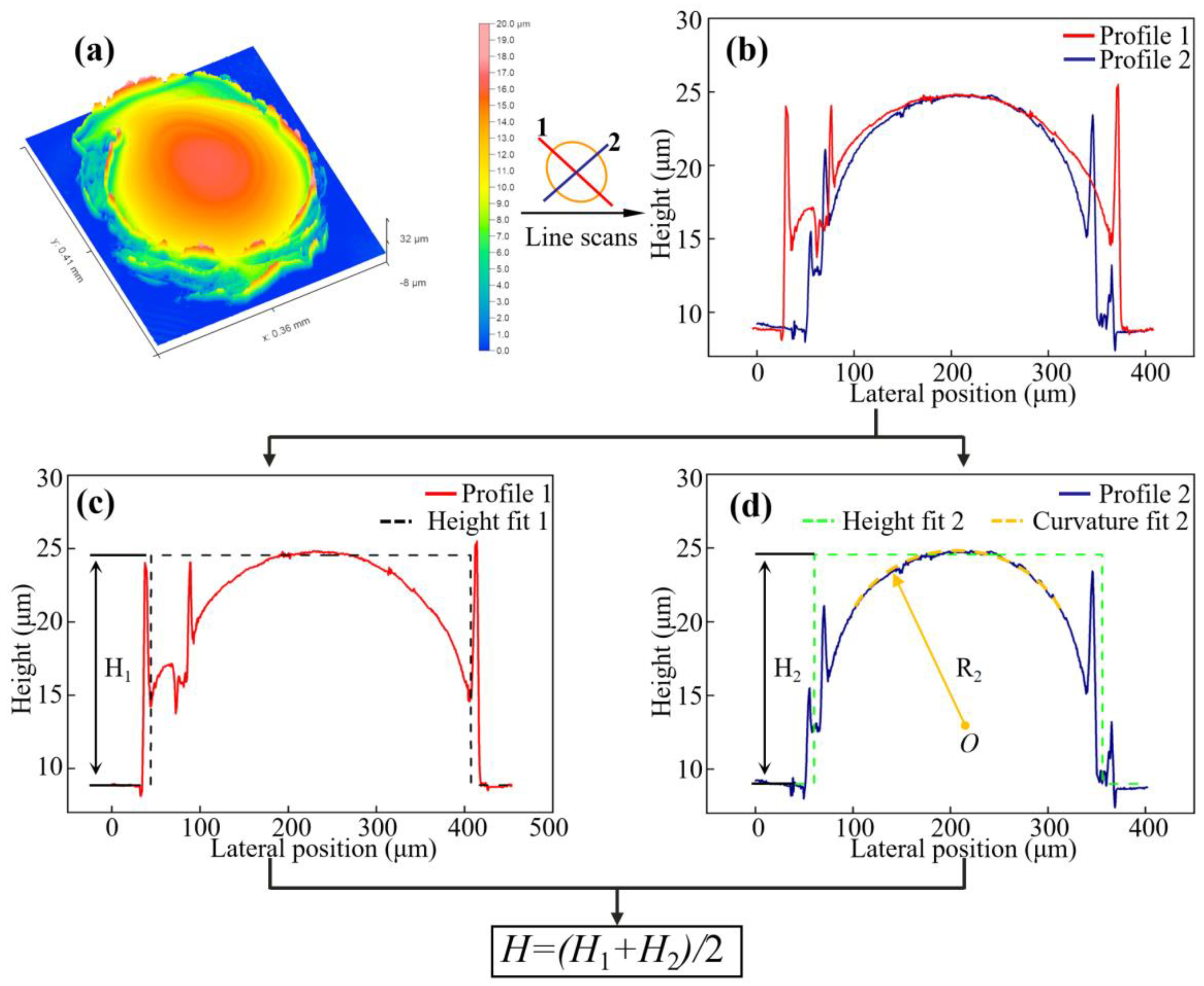
3.4. Characterization of the Filling Capacity

After the hot embossing process, a microlens would be formed at the center of glass surface. Figure 5 illustrates the quantification method of filling capacity of glass. Firstly, surface topography of microlens on embossed glass is measured by the confocal laser scanning microscope (VK-250, Keyence, Osaka, Japan). The raw data of surface topography of microlens is leveled. After that, two surface profiles are extracted from two orthogonal line scans of the surface topography of microlens, both of which pass through the vertex of the microlens. The extracted surface profiles are then fitted by a step function for calculating maximum height with a fitting error. The average value of calculated maximum heights of the two surface profiles is used to quantify the filling capacity of glass in this study. Furthermore, the central part of profile 2 is fit by an arc function using least square method. The curvature radius, R2, of the best-fit profile is then used to evaluate the filling characteristics of glass.

4. Results and Discussion

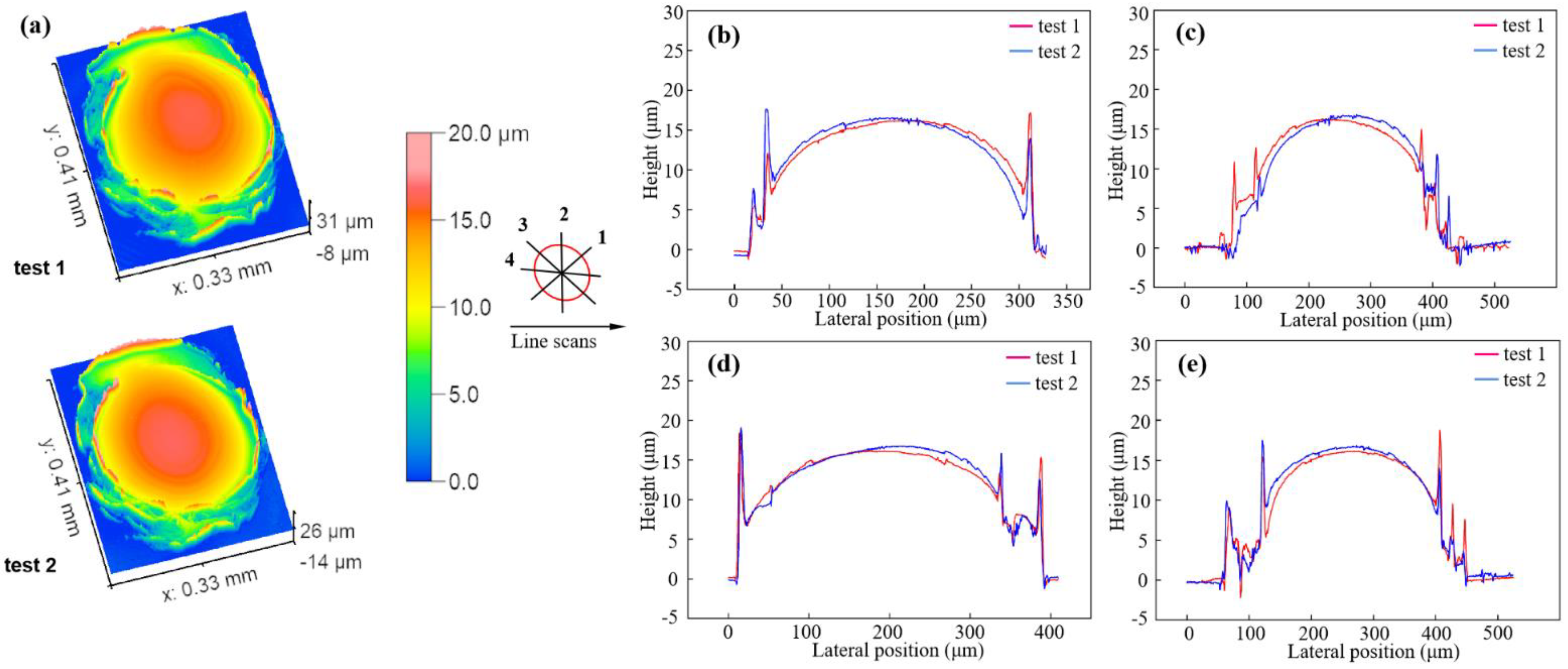
4.1. Reproducibility of the Novel Rapid Hot Embossing Device

Figure 6a compares the surface topography of two glass microlens embossed under the same experiment condition, which are relatively resemble each other. Moreover, the surface profiles of both microlenses along the line scans are aligned in Figure 6b–e. Their maximum heights are calculated to be 15.972 ± 0.325 μm and 16.084 ± 0.385 μm, respectively, showing little differences. The similarity in both the surface topography and the maximum height of glass microlenses demonstrates the satisfactory reproducibility of the novel rapid hot embossing device, which can ensure the reliability of the results of subsequent experiments.

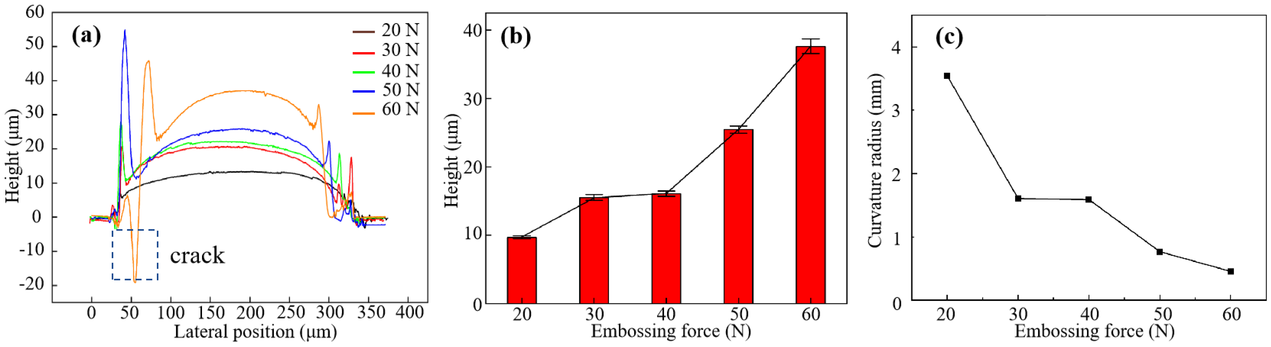
4.2. Effect of Embossing Force on the Filling Capacity

Figure 7a–c illustrate the profiles, maximum heights and curvature radii of glass microlenses under various embossing forces, respectively. The error bars in Figure 7b indicate the fitting errors. Apparently, increasing embossing force leads to a higher maximum height, but a smaller curvature radius of microlenses. This is attributed to that higher pressures promote the deformation and flowing of glass at elevated temperatures in the embossing step. However, due to the cracks at the edge of microlens caused by stress concentration, the deep pit is generated at a embossing force of 60 N (see the dotted square in Figure 7a). This reveals that an excessive embossing force may result in the breakage of microlens. In fact, the experimental results demonstrate that microstructures can be imprinted on glass by applying a small embossing force of 20 N under appropriate temperatures.

4.3. Effect of Embossing Temperature on the Filling Capacity

It is known that the deformation of N-BK7 glass is not appreciable when the temperature is below its transition point (~557 °C), even under a considerably large embossing force. In fact, the difficulty of the deformation and flowing of glass is largely determined by its viscosity which is quite sensitive to the temperature. Therefore, it is not surprising that the embossing temperature shows the most significant influence on the filling capacity of glass. As shown in Figure 8a,b, the maximum height of microlens soars from 3.78 μm to 48.99 μm, as the embossing temperature increases from 700 °C to 740 °C. According to Figure 8a, the shape of the embossed microstructure gradually changes from trapezoidal platform to simple hemisphere, finally to cylindrical hemisphere with the inevitable corners caused by the adhesion and friction along the sidewall. Correspondingly, the curvature radius dramatically decreases as embossing temperature increases, as seen in Figure 8c.

4.4. Effect of Soaking Time on the Filling Capacity

Due to the low thermal conductivity of glass and the non-negligible interfacial thermal resistance, the surface temperature of glass preform is always lower than that of the rapid heating module in the rapid heating step. When it comes to the soaking step, the rapid heating module retains a constant temperature, while the surface temperature of glass preform continues increasing due to heat transfer. Therefore, the extension of soaking time can decrease the glass viscosity and prolong the viscoelastic deformation time, and thus improving the filling capacity of glass. Figure 9a–c suggest that increasing soaking time can indeed lead to a higher maximum height and a small curvature radius of the glass microlens. Nevertheless, the improvement of filling capacity is not so impressive, as the embossing temperature is insufficiently high. On the other hand, pits or cracks may be generated on the surface of glass microlenses under extended soaking time.

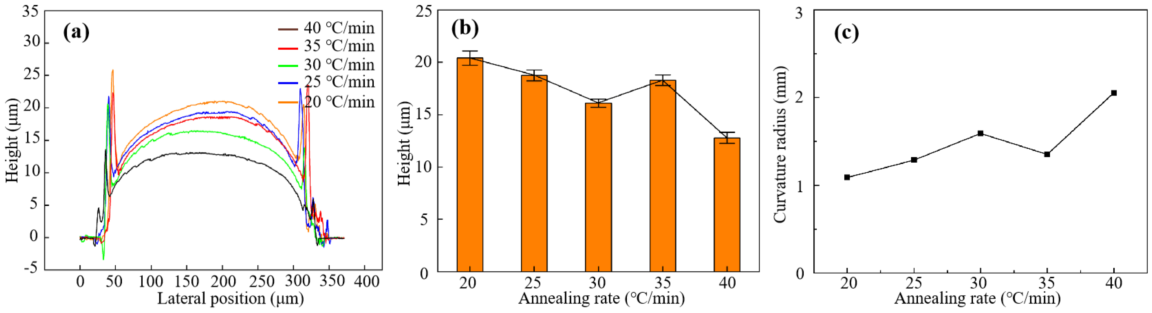
4.5. Effect of Annealing Rate on the Filling Capacity

In the initial stage of cooling step, the embossing force is still applied to glass preform until the temperature of the rapid heating module decreases to 511 °C. Although the deforming difficulty increases with the decrease of temperature, the glass preform keeps deforming during this period. A faster annealing rate means a shorter time for the viscoelastic deformation of glass in the cooling step. Therefore, the maximum height of microlens is expected to slightly decrease as the annealing rate increases, which is proved by Figure 10a,b. Furthermore, the curvature radius increases linearly with annealing rate, as seen in Figure 10c.

5. Conclusions

A novel rapid hot embossing approach is proposed for microstructuring of optical glass in this study. The detailed information about the precision loading module and the rapid heating module is introduced. The filling capacity of N-BK7 glass is quantified by the maximum height of the embossed microlens. Effects of process parameters on the filling capacity of glass in the novel rapid hot embossing process are evaluated. Some conclusions are drawn as follows:
(1)
The tailor-made novel rapid hot embossing device allows a maximum temperature of 800 °C and a heating rate of 300 °C/min, with decent temperature control accuracy and uniform temperature distribution. Besides, it is demonstrated to have a satisfactory reproducibility in imprinting microlenses on the N-BK7 glass.
(2)
The glass microlens can be fabricated by just applying a small embossing force of 20 N at the appropriate temperature.
(3)
The filling capacity of glass is improved by increasing embossing force, embossing temperature and soaking time, but decreasing annealing rate.
(4)
The filling capacity of N-BK7 glass is more sensitive to embossing force and embossing temperature, compared to soaking time and annealing rate.

Author Contributions

Conceptualization, F.G., G.Y. and J.L.; methodology, J.L., X.W. and G.Y.; software, J.L. and G.Y.; validation, J.L., X.W. and G.Y.; formal analysis, J.L., X.W. and G.Y.; investigation, J.L. and G.Y.; resources, F.G. and G.Y.; data curation, J.L. and X.W.; writing—original draft preparation, J.L. and G.Y.; writing—review and editing, J.L., F.G. and G.Y.; visualization, J.L. and G.Y.; supervision, F.G. and G.Y.; project administration, G.Y.; funding acquisition, G.Y. All authors have read and agreed to the published version of the manuscript.

Funding

This research was funded by Shenzhen Science and Technology Innovation Commission (SGDX20190919094403772) and Shenzhen University (000002111214).

Institutional Review Board Statement

Not applicable.

Informed Consent Statement

Not applicable.

Data Availability Statement

Data is contained within the article.

Acknowledgments

The authors would like to appreciate the colleagues and advisor for their help to improve the paper.

Conflicts of Interest

The authors declare no conflict of interest.

References

  1. Li, Y.; Li, K.; Gong, F. Fabrication and Optical Characterization of Polymeric Aspherical Microlens Array Using Hot Embossing Technology. Appl. Sci. 2021, 11, 882. [Google Scholar] [CrossRef]
  2. Tagantsev, D.K. Producing optical microelements from glasses by means of extrusion. J. Opt. Technol. 2014, 81, 748–753. [Google Scholar] [CrossRef]
  3. Colafemina, J.P.; Militão Dib, M.H.; Jasinevicius, R.G. Hot embossing of aspherical Fresnel microlenses: Design, process, and characterization. Int. J. Adv. Manuf. Technol. 2021, 113, 935–953. [Google Scholar] [CrossRef]
  4. Lee, Y.-H.; Ke, K.-C.; Chang, N.-W.; Yang, S.-Y. Development of an UV rolling system for fabrication of micro/nano structure on polymeric films using a gas-roller-sustained seamless PDMS mold. Microsyst. Technol. 2018, 24, 2941–2948. [Google Scholar] [CrossRef]
  5. Greener, J.; Li, W.; Ren, J.; Voicu, D.; Pakharenko, V.; Tang, T.; Kumacheva, E. Rapid, cost-efficient fabrication of microfluidic reactors in thermoplastic polymers by combining photolithography and hot embossing. Lab Chip 2010, 10, 522–524. [Google Scholar] [CrossRef] [PubMed]
  6. Lee, K.L.; Wu, T.Y.; Hsu, H.Y.; Yang, S.Y.; Wei, P.K. Low-Cost and Rapid Fabrication of Metallic Nanostructures for Sensitive Biosensors Using Hot-Embossing and Dielectric-Heating Nanoimprint Methods. Sensors 2017, 17, 1548. [Google Scholar] [CrossRef] [PubMed] [Green Version]
  7. Schneider, P.; Steitz, C.; Schäfer, K.H.; Ziegler, C. Hot embossing of pyramidal micro-structures in PMMA for cell culture. Phys. Status Solidi 2009, 206, 501–507. [Google Scholar] [CrossRef]
  8. Li, K.; Xu, G.; Liu, X.; Gong, F. Deformation Behavior of Glass Nanostructures in Hot Embossing. ACS Appl. Mater. Interfaces 2020, 12, 36311–36319. [Google Scholar] [CrossRef] [PubMed]
  9. Yun, D.; Kim, J.-B. Material modeling of pmma film for hot embossing process. Polymers 2021, 13, 3398. [Google Scholar] [CrossRef] [PubMed]
  10. Haponow, L.; Kettle, J.; Allsop, J. Optimization of a continuous hot embossing process for fabrication of micropyramid structures in thermoplastic sheets. J. Vac. Sci. Technol. B 2021, 39, 012203. [Google Scholar] [CrossRef]
  11. Tsai, Y.-P.; Hung, J.-C.; Yin, L.-C.; Hung, C. Ultrasonic vibration-assisted optical glass hot embossing process. Int. J. Adv. Manuf. Technol. 2012, 60, 1207–1213. [Google Scholar] [CrossRef]
  12. Fang-Yu, F.; Hsin-Chung, C.; Chiung-Fang, H.; Yi, L.; Wei-Chun, L.; Yung-Kang, S.; Liping, W. Replicability of process conditions of ultrasonic hot embossing for micropattern fabrication on thermoplastic substrates. J. Manuf. Process. 2020, 60, 283–291. [Google Scholar] [CrossRef]
  13. Cheng, C.; Ke, K.-C.; Yang, S.-Y. Application of graphene–polymer composite heaters in gas-assisted micro hot embossing. RSC Adv. 2017, 7, 6336–6344. [Google Scholar] [CrossRef] [Green Version]
  14. Nagarajan, P.; Yao, D. Uniform shell patterning using rubber-assisted hot embossing process. I. Experimental. Polym. Eng. Sci. 2011, 51, 592–600. [Google Scholar] [CrossRef]
  15. He, Y.; Wu, W.; Zhang, T.; Fu, J. Micro structure fabrication with a simplified hot embossing method. RSC Adv. 2015, 5, 39138–39144. [Google Scholar] [CrossRef]
  16. Ming, W.; Chen, Z.; Du, J.; Zhang, Z.; Zhang, G.; He, W.; Ma, J.; Shen, F. A comprehensive review of theory and technology of glass molding process. Int. J. Adv. Manuf. Technol. 2020, 107, 2671–2706. [Google Scholar] [CrossRef]
  17. Liu, X.; Mo, R.; Li, K.; Shen, J.; Ma, J.; Gong, F. Manufacturing of 3D Microlens Array Mold on Bulk Metallic Glass by Self-Aligned Multi-Ball Hot Embossing. Int. J. Precis. Eng. Manuf.-Green Technol. 2020, 8, 1209–1223. [Google Scholar] [CrossRef]
  18. Omar, F. Hot Embossing Process Parameters: Simulation and Experimental Studies. Ph.D. Thesis, Cardiff University, Cardiff, UK, 2013. [Google Scholar]
  19. Li, K.; Xu, G.; Luo, H.; Liu, X.; Gong, F. Glass flow behaviors in micro-channels during hot embossing. Ceram. Int. 2020, 46, 21517–21526. [Google Scholar] [CrossRef]
Figure 1. (a) Assembly of the novel rapid hot embossing tool. (b) 3D model of the novel rapid hot embossing tool. (1) Leveling foot; (2) optical table; (3) XY tilting stage; (4) motorized vertical stage; (5) XYR positioning stage; (6) mica plate; (7) rapid heating module; (8) spherical indenter; (9) fixed collar; (10) mounted plate; (11) linear bearing; (12) locking ring; (13) guiding columns; (14) weights.
Applsci 12 03404 g001
Figure 2. (a) Schematic of the rapid heating module and (b) the recorded temperature signals at four different positions in the heating test.
Applsci 12 03404 g002
Figure 3. (a) Optical microscopy of the microhole at the central of the SiC lower mold. (b) Glass, mold and the mold kit.
Applsci 12 03404 g003
Figure 4. Schematics of the novel rapid hot embossing process.
Applsci 12 03404 g004
Figure 5. Quantification method of filling capacity. (a) Surface topography of microlens on embossed glass, (b) surface profiles extracted from the surface topography of microlens, (c) fitting of profile 1, (d) fitting of profile 2.
Applsci 12 03404 g005
Figure 6. (a) Surface topography and (b) surface profiles 1, (c) surface profiles 2, (d) surface profiles 3 and (e) surface profiles 4 of embossed glass microlenses in the repeating experiments.
Applsci 12 03404 g006
Figure 7. (a) Profiles, (b) maximum heights, and (c) curvature radii of microlenses under various embossing forces.
Applsci 12 03404 g007
Figure 8. (a) Profiles, (b) maximum heights, and (c) curvature radii of microlenses under various embossing temperature.
Applsci 12 03404 g008
Figure 9. (a) Profiles, (b) maximum heights, and (c) curvature radii of microlenses under various soaking time.
Applsci 12 03404 g009
Figure 10. (a) Profiles, (b) maximum heights, and (c) curvature radii of microlenses under various annealing rate.
Applsci 12 03404 g010
Table 1. Design of the hot embossing experiment.
Experiment NumberEmbossing Force (N)Embossing Temperature (°C)Soaking Time (Min)Annealing Rate (°C·Min)
120720830
230720830
340720830
450720830
560720830
640700830
740710830
840730830
940740830
1040720630
1140720730
1240720930
13407201030
1440720820
1540720825
1640720835
1740720840
Publisher’s Note: MDPI stays neutral with regard to jurisdictional claims in published maps and institutional affiliations.

