Abstract
To evaluate the functional reliability of the pyrotechnic igniter in the failure mode of unstable combustion at low temperature, a reliability and reliability sensitivity analysis method based on the combination of an interior ballistic model and Kriging reliability method is proposed. Through the deterministic interior ballistic simulation, the failure mode of low temperature unstable combustion of the pyrotechnic igniter is examined, while the random variables are introduced to establish the ignition nonlinear implicit function of the pyrotechnic igniter. The ignition display function of the pyrotechnic igniter is established by the Kriging model, which avoids the repeated calculation of true limit state function values. This study provides an efficient approach to evaluate the ignition reliability of the pyrotechnic igniter and compared with the traditional Monte Carlo method to verify the accuracy of the results. Finally, reliability-based sensitivity indices are presented to quantify the significance of random parameters. It is shown that the influence of the uncertainties can be precisely described, and the diameter of the nozzle plays a dominant role in ignition reliability. Additionally, ignition experiments of nozzles with different diameters were performed to verify the result of sensitivity. This can further support the detailed design of the pyrotechnic igniter.
1. Introduction
The pyrotechnic igniter is an ignition device of the hydrogen-oxygen rocket engine, which is widely used in aerospace fields. The success or failure of ignition is crucial to the normal operation of the hydrogen-oxygen rocket engine [1,2,3]. A well-designed igniter will burn steadily under any condition. In order to improve the ignition reliability of the igniter, it is necessary to design the igniter in the low-temperature unstable combustion failure mode. In order to characterize the pyrotechnic igniter output, M. N. Skaggs et al. [4] used high-speed schlieren imaging to observe critical features of the post-combustion flow and designed a high-speed schlieren imaging diagnostic system for observing subsonic and supersonic multiphase material motion from the initiation of two types of titanium-based pyrotechnic igniters into the surrounding environment. Juyoung Oh et al. [5] introduced the effects of heating and humidity on ageing of a NASA standard pyrotechnic igniter. Calculations using Van’t Hoff equation indicate that moisture shortened the lifespan of the unaged zirconium potassium perchlorate (ZPP) up to about 85% under extreme relative humidity conditions, while significantly deteriorating the heat of reaction, sensitivity, and thus increased the risk of a misfire. Abdullah Ulas et al. [6] studied the performance of a boron/potassium-nitrate based pyrotechnic igniter. Kanagaraj Gnanaprakash et al. [7] studied ignition and combustion behavior of pyrotechnic materials based on zirconium as fuel and investigated potassium perchlorate or iron oxide as oxidant for various aging conditions. Qian Zhong et al. [8] fabricated the boron/potassium nitrate by electrostatic spraying to enhance their combustion efficiency and capability of igniting target materials and used the closed chamber tests to record the process of boron/potassium nitrate igniting guanidine nitrate/basic cupric nitrate gas generator. The aforementioned research studies on the pyrotechnic igniter are simply deterministic simulation analysis. However, ignition of the pyrotechnic igniter is a random process with the uncertainties of working loads, geometrical dimensions, as well as material properties, especially as low-temperature igniting is more prone to failure. Owing to the increased application of the pyrotechnic igniter in the field of aerospace, the reliability requirements are increasing. It is necessary to conduct an ignition reliability analysis of the pyrotechnic igniter to understand the influence of the material properties, structural size, machining error, and other factors on its igniting reliability, and appropriate design measures should be proposed to improve the ignition reliability level.
Although the importance of reliability has been widely accepted, the reliability analysis is still a complicated task to reach. One of the main challenges is that, due to the highly nonlinear and coupling relations among variables, it is difficult for a complex structure to establish an explicit function between basic random variables and the structural response by using analytical methods [9]. Therefore, the ignition reliability analysis of the pyrotechnic igniter is an implicit function problem. As a result, numerical simulations have been introduced to establish the implicit function. Researchers have proposed many methods to improve the computational efficiency in solving this problem. According to probabilistic theory, the Monte Carlo Simulation (MCS) [10,11] has the highest accuracy for complex and highly nonlinear systems. However, the MCS requires a large sample size to achieve high simulation credibility, and it is inefficient, consuming extensive computational time. In order to improve the calculation efficiency of the MCS, the surrogate model is mainly used to establish a response model to improve the efficiency of reliability analysis. Commonly used surrogate models include response surfaces [12,13], support vector machines [14,15], neural networks [16,17], and the Kriging model [18,19,20]. This paper focuses on the Kriging model due to its validity being independent of the existence of random errors, and it has a good fitting effect for the problems of high nonlinearity and sudden changes in the local response. The Kriging surrogate model is used for global and local approximations [21,22,23,24,25]. When it comes to the pyrotechnic igniter, however, the current method to evaluate the reliability of the pyrotechnic igniter is mainly through ignition tests, which are time-consuming and expensive. To our knowledge, there are few numerical studies on the ignition reliability analysis of pyrotechnic igniters.
Therefore, it is essential to develop an efficient and accurate numerical way to conduct the ignition reliability analysis for the pyrotechnic igniter. Based on coupling the interior ballistic model and Kriging model, this paper proposes an ignition reliability analysis procedure of the pyrotechnic igniter concerning the failure mode of unstable combustion at low temperature. The method is applied to evaluate the reliability of a pyrotechnic igniter and is verified by comparing reliability results with that of MCS. The importance ranking of design variables extracted from propellant combustion parameters, geometric size, and material properties are obtained with sensitive analysis to assist the pyrotechnic igniter design and optimization.
The remainder of this paper is organized as follows. In Section 2, the working principle of the pyrotechnic igniter is introduced, and the function failure mode of a pyrotechnic igniter is defined to establish an implicit function. Section 3 conducts the function deterministic simulation and failure modes analysis of the pyrotechnic igniter based on the interior ballistic model. In Section 4, the Kriging model method is constructed to display the function, and the effects of independent random parameters on reliability and reliability sensitivity are developed. Then, by comparing with the results of MCS, the validity of this method is verified. To validate the result of reliability sensitivity, igniting experiments were performed. Finally, the conclusions are provided in Section 5.
2. Failure Analysis of Low-Temperature Unstable Combustion of the Pyrotechnic Igniter
2.1. Basic Structure and Working Principle
The structure of a pyrotechnic igniter is shown in Figure 1. The pyrotechnic igniter includes the shell, electric igniter, ignition powder, igniter case, propellant, diaphragm, nozzle, and other parts. The igniter case is filled with the boron potassium nitrate (BPN) and composite modified double-base propellant (CMDB). The main charge is the CMDB in main charge chamber. The ignition process of the pyrotechnic igniter can be divided into the combustion of the BPN and CMDB in the igniter case and the combustion of the CMDB in the main charge chamber.

Figure 1.
Cross section of a pyrotechnic igniter.
During the combustion of the BPN and CMDB in the igniter case, the BPN is thermally initiated through contact with the electric igniter, and the BPN combustion releases high-energy particles to ignite CMDB. The energy released by the combustion of the BPN and CMDB breaks through the aluminum foil at the bottom of the igniter case, and then ignites the CMDB in the main charge chamber. During the combustion of the CMDB in the main charge chamber, the CMDB combustion generates a large amount of gas. After breaking the diaphragm, the flame enters the gas generator and ignites the liquid hydrogen and liquid oxygen mixture in the OHRM.
2.2. Failure Mode
This type of pyrotechnic igniter can be ignited normally at room temperature and high temperature. However, the pyrotechnic igniter shows unstable combustion at low temperatures, as shown in Figure 2. There are many factors that affect the combustion stability of the pyrotechnic igniter, mainly including propellant compositions, geometric size and other factors. However, these factors usually have inherent dispersion, so that the pyrotechnic igniter may not be able to achieve its specified functions. It is necessary to quantify the influence of the input random variables on the ignition performance of the pyrotechnic igniter. If the design parameters cannot meet the requirements, their reliability should be improved according to the sensitivity results.
Figure 2.
Unsteady combustion P-t curve of the pyrotechnic igniter.
The working performance output of the pyrotechnic igniter is a pressure-time parameter, i.e., P-t curve, as shown in Figure 3. In Figure 3, Pm is the peak pressure of combustion stage of the BPN and CMDB, Pi is the end pressure of combustion stage of the BPN and CMDB, ts is the starting time of combustion stage of the BPN and CMDB, tv is the working combustion time of the pyrotechnic igniter, I is the ignition impulse. The igniting impulse considers the pressure and working time in the combustion chamber, and is also an important monitoring index of propellant combustion energy. Therefore, the ignition impulse is taken as the sensitive parameter to evaluate the working performance of igniter. I is as follows [26]:
Figure 3.
P-t curve of pyrotechnic igniter and characteristic parameter.
According to the stress–strength interference model [27], the ignition fails when the I is less than the Imin. In this model, the residual strength is defined as:
where, the Imin is the minimum ignition impulse and obtained from a normal ignition experiment at low temperature, Imin = 0.87.
3. Deterministic Simulation of Low Temperature of the Pyrotechnic Igniter
3.1. Simulation Model of the Pyrotechnic Igniter
According to the classical interior ballistic theory [28,29] and the working principle of the pyrotechnic igniter, the low-temperature ignition of the pyrotechnic igniter is simulated by using the Simulink module of MATLAB. The interior ballistic equations are as follows.
To simplify the combustion model, the shape functions of gun powder are constructed using Equations (3) and (4) [30].
where χ, λ, and μ are the shape characteristic quantities of the propellant, ψ is the combustible relative mass of the propellant, σ is the relative surface area of the combustible powder, Z = e/el represents the relative thickness, e is the arc thickness at any time, and el is the starting arc thickness.
Burning equation of the gun powder based on Saint Robert’s law is used to calculate the pressure of the gas inside the chamber [31]:
where P, n, and u are the pressure, burning rate-pressure exponent and burning rate coefficient.
The mass generation rate of the gas from the BPN and CMDB are estimated as follows [32,33]:
where ηg is the mass fraction of gas in the combustion product of the propellant, mp is the loading mass of the propellant and represent different types of gun powder.
The device has good sealing property and there is no mass exchange between the system and the outside world. Hence, the law of conservation of mass in a control volume of the combustion chamber is given by the following equation:
where is the gas mass change rate in the igniter case. is the gas mass change rate in the main charge chamber. is the mass production rate of propellant combustion products in igniter case, is the mass production rate of propellant combustion products in the main charge chamber. is the rate of gas flow from ignition chamber to main charge chamber. is the rate of gas flow from main charge chamber to nozzle.
According to the gas flow theory [34], is calculated by the following equation:
where Ae is the cross-sectional area of the nozzle, k is the specific heat ratio of the fuel gas, R is a gas constant, PIC is ignition case pressure, PMC is the pressure of the main charge chamber.
The energy conservation relation of the internal gas and can be expressed as Equations (10) and (11) [35].
where cv and cp are the specific heats of constant volume and pressure of the gas, respectively, Tf is the explosion temperature at constant pressure, TIC and TMC are the temperature of ignition case and main charge chamber, respectively, and are the heat exchange rates of ignition case and main charge chamber to the outside world, respectively.
The intermolecular attraction of high temperature and high pressure gas products produced by propellant combustion is very small compared with the pressure in the chamber. The gas products in the ignition case and the main charge chamber obey the Nobel–Abel equation of state. The ideal gas state equations are given by Equations (12) and (13) [36,37].
where mIC and mMC are the mass of mixed gas in the igniter case and main charge chamber, respectively, α(·) is the covolume.
Equation (12) is differentiated to obtain Equation (14).
where R can be obtained by Equation (15).
By substituting Equation (13) and Equation (14) into Equation (11), the change rate of pressure in the ignition cartridge is derived as Equation (16).
Similarly, the change rate of pressure in the main charge chamber can be obtained:
Due to the combustion of gun powder, the volume of the combustion chamber will change. The change rate of the volume of the ignition case and the main charge chamber can be calculated by Equation (18).
where ρ(·) is the density of different types of solid gun powder.
A simplified model of heat exchange between the propellant products and the outside through the cavity wall is established according to [38], and can be estimated using Equations (19) and (20).
where h is a constant convective heat transfer coefficient, Tw is the temperature of the vessel wall, σs is the Stefan–Boltzmann constant, Ar is the absorption rate of the vessel wall, Em is the net emissivity of the product, and Aw is the instantaneous surface area of the vessel side wall in contact with the product.
The combustion parameters applied to this combustion model are listed in Table 1.

Table 1.
Parameters for the analytical combustion model.
3.2. Simulation Result Compared with Experimented Result
To validate the established simulation model, ignition experiments using the developed pyrotechnic igniter were conducted. The experiment concept is described in Figure 4. Figure 5 shows photographs of the experiment setup. The strain sensor is used to test the pressure of the ignition chamber. Three ignition experiments were performed. As seen from Figure 6, the simulation result is in accordance with the experimental result. Table 2 summarizes the characteristic parameter of the simulation model and experiment, showing quite small relative differences between the experimental and analytical results.

Figure 4.
Configuration of the experiment.
Figure 5.
The experiment setup.
Figure 6.
Comparison between the simulation model and the experiment results.
Table 2.
Comparison between the Simulation model and the experiment characteristic parameters.
4. Reliability and Reliability Sensitivity Analysis Method of the Igniter
4.1. Kriging Model of the Igniter
The limit state functions I(x) are highly nonlinear and implicit. The Kriging model with a three-level Full Factorial method (TLFF) [39] is employed to predict the limit state functions due to its high computational accuracy and efficiency. An initial Kriging model is established based on the Design of Experiments (DoE) and the initial DoE is constructed by a TLFF method in this paper. According to the Kriging theory, the output function, , and random variable, x, are related as follows [40]:
where is the regression coefficient, is the basis function of the Kriging model. is a random correction process that provides local approximation and obeys the normal distribution, , and the covariance is nonzero. Therefore, the covariance matrix can be expressed as:
where represents the correlation function between the sampling points xi and xj. This plays a decisive role in the accuracy of the simulation. The correlation function applied in this paper is a Gaussian type expression, as follows:
where is an unknown related parameter.
The Kriging approximation model of can be expressed as Equation (24) [41].
where is the estimated value of , I is the column vector composed of the response value of the experimental design sample data, that is, , F is the m × n order matrix composed of the regression model at m sample points, and r(x) is the correlation function vector between the experimental data sample points and the prediction points and can be expressed as Equation (25).
and variance estimate are given as Equation (26).
The relevant parameter, , is obtained by calculating the maximum value of the maximum likelihood estimation, as shown in Equation (27).
Equations (2) and (24) are combined to obtain the display function given by Equation (28):
when the approximated performance function Equation (28) is used for probabilistic evaluation, the failure probability can be calculated as:
is the joint probability density function of the random vector x. is the indication function of the failure domain, and .
According to the basic principle of MCS [42], the estimated probability of failure is:
where N is the number of sample points extracted from the joint probability density function of random variables, NF is the number of sample points falling in the failure domain.
Therefore, the ignition reliability of the igniter under low temperature combustion instability failure mode is:
4.2. Reliability Sensitivity Analysis
According to [43], the parameter sensitivity calculation equation is defined as follows:
where is the reliability index according to [44], that is, . T(x) is the transformation function of u and x [45]. can be the mean values or standard deviations of the random variables, x and , where represents the standard deviation of the ith random variable when i = j, and its value is zero when i ≠ j. u is an independent standard normal random vector, given by Equation (33).
where y is the random variable vector of the equivalent standard normal transformation of x, obtained based on the Nataf transformation [46]. is the lower triangular matrix obtained by the Choleskey decomposition of the correlation coefficient matrix of y.
4.3. Reliability Simulation Implementation of the Pyrotechnic Igniter
According to the above reliability analysis method, the performance reliability simulation of pyrotechnic igniter includes the following steps:
Step 1. Enter the random variable, x, and its distribution type, as shown in Table 3;
Table 3.
Key design parameters for the pyrotechnic igniter.
Step 2. The sample data of m groups are obtained by a TLFF design to reduce the number of experiments. After obtaining m group samples through experimental optimization design, the samples are inputted into the ignition simulation model of the pyrotechnic igniter established by MATLAB to obtain the ignition impulse value I(x). Among them, all MATLAB software packages should be executed in a batch mode to automate the simulation process;
Step 3. The Kriging model, , is fitted based on m groups of the sample data;
Step 4. The display function, , is established based on the Kriging model of the ignition impulse ;
Step 5. The reliability and sensitivity are analyzed based on the display function, .
The reliability simulation flow chart is shown in Figure 7.
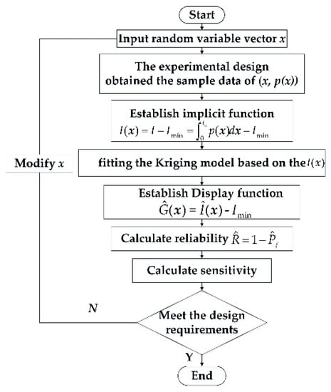
Figure 7.
Reliability simulation flow chart of the pyrotechnic igniter.
The ignition simulation workflows of the pyrotechnic igniter are constructed by applying the aforementioned steps of the reliability analysis, as shown in Figure 8. The arrows in the figure represent the running order of the tasks. The details of the nodes in the simulation workflow are listed in Table 4.
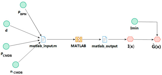
Figure 8.
Ignition simulation workflow of the pyrotechnic igniter.
Table 4.
Nodes in the simulation workflow.
5. Reliability and Sensitivity Analysis Results
From the above procedure, the reliability is analyzed based on the Kriging + TLFF + MCS, and the correctness of the reliability analysis results is verified by using the MCS method. The reliability results are presented in Table 5. The results, which are gained by the above methods, and the relative error, are 1.2%. The Kriging + TLFF + MCS method requires 81 samples to construct the initial Kriging model. However, the MCS sampling requires about 106 performance function evaluations. Therefore, the Kriging + TLFF + MCS method is suitable for the functional reliability analysis of the pyrotechnic igniter.
Table 5.
Results for the ignition reliability of the pyrotechnic igniter.
According to the ignition reliability simulation program of the pyrotechnic igniter, the Kriging response surface model of some random variables, x, is shown in Figure 9.
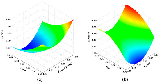
Figure 9.
Response surface of the Kriging model. (a) I~(d, ρCMDB), (b) I~(d, nCMDB).
Table 6 shows the results of sensitivity analysis of ignition of the pyrotechnic igniter based on Equation (32). Among these, ρBPN, nCMDB and ρCMDB have a positive influence on the results of the mean sensitivity analysis; that is, increasing the mean value of these parameters improves the ignition reliability of the pyrotechnic igniter. Parameter d has a negative effect on the mean sensitivity; in other words, reducing the mean value of its parameters improves the ignition reliability of the igniter. The sensitivity results of the standard deviation indicate that reducing the standard deviation of each variable aids in improving the reliability. From the perspective of the design, the decrease in d is what mainly leads to the higher ignition reliability.
Table 6.
Sensitivity results for the pyrotechnic igniter.
As for the pyrotechnic igniter, it has a high reliability requirement, usually with 0.999 at least for the igniter device. Then, it should take some measures for reliability improvement according to the sensitivity results in Table 6. The straightest way towards improvement may be by decreasing the mean of the nozzle diameter d. The reliability results with different mean values of nozzle diameter d are shown in Figure 10, which reveals that the igniter can meet its reliability requirement once the mean values of nozzle diameter d are controlled to be lower than 3.5 mm.
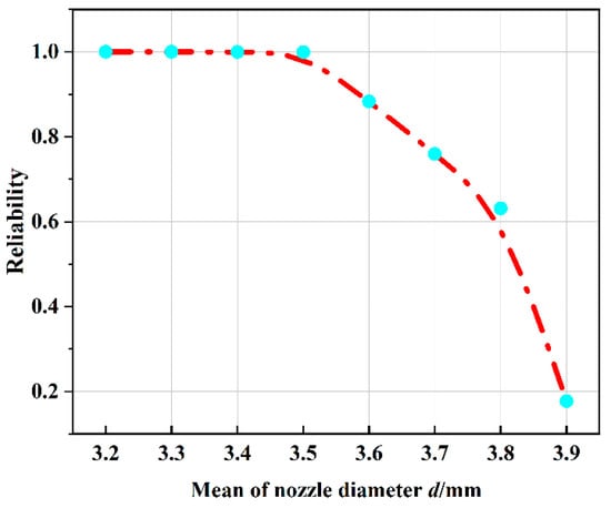
Figure 10.
Reliability results with different means of the variable d.
According to the above analysis, igniters with different nozzles are used for the test, and the test results are shown in Figure 11.
Figure 11.
Experiment of different nozzles of the pyrotechnic igniter.
Figure 11 shows that with the increase in nozzle diameter, the failure mode of unstable combustion is more likely to appear, which verifies the results of sensitivity analysis and provides valuable reference for the nozzle structure design of the igniter.
6. Conclusions
Aiming at evaluating the ignition reliability of the pyrotechnic igniter under the failure mode of low temperature unstable combustion, a framework and corresponding approach were proposed based on the combination of the ignition simulation model of the pyrotechnic igniter and Kriging + TLFF + MCS, and its effectiveness was verified:
- (1)
- The ignition simulation model of the pyrotechnic igniter was established, and the accuracy of the simulation model was verified experimentally. The results show the experimental and analytical results are in good agreement;
- (2)
- The nonlinear implicit function of pyrotechnic igniter is established with ignition impulse as performance parameter;
- (3)
- The Kriging + TLFF + MCS method is verified by analyzing the ignition reliability of the pyrotechnic igniter. The results show that the relative deviations between the Kriging + TLFF + MCS with 81 samples and the MCS are less than 1.2%;
- (4)
- Finally, the sensitivity analysis is performed to quantify the importance ranking of random variables, which offers a valuable insight into reliability-based design and optimization process for the pyrotechnic igniter. The results indicate parameter d is the main factor affecting the ignition reliability of the pyrotechnic igniter, followed by nMLR, ρCMDB and ρBPN. Further improvement measures are presented based on reliability and sensitivity results for the pyrotechnic igniter and the correctness of the improved measures was verified by experiment.
Compared to the reliability assessment by experiment, the reliability analysis method based on numerical simulations proposed in this paper provides a valuable insight into the reliability-based design and optimization process for a pyrotechnic igniter.
Author Contributions
L.N. carried out the experimental work and wrote the main manuscript text. Y.L. designed the experiments. J.W. completed the simulation analysis. N.Y., H.D. and H.T. corrected and reviewed the manuscript. All authors have read and agreed to the published version of the manuscript.
Funding
This research received no external funding.
Institutional Review Board Statement
Not applicable.
Informed Consent Statement
Not applicable.
Data Availability Statement
Data are contained within this article.
Acknowledgments
The authors thank the reviewers for their great help on the article during its review progress.
Conflicts of Interest
The authors declare no conflict of interest.
References
- Cai, J.R. Design Principle of Initiating Explosive Devices; Beijing Institute of Technology Press: Beijing, China, 1999. [Google Scholar]
- Zhou, C.; Yu, N.; Wang, J.; Jin, P.; Cai, G. Analysis of dynamic characteristics and sensitivity of hydrogen-oxygen expansion cycle rocket engine system. Acta Astronaut. 2021, 189, 624–637. [Google Scholar]
- Saurel, R.; Loraud, J.C.; Larini, M. Optimization of a pyrotechnic igniter with the release of reactive particles. Shock Waves 1991, 1, 121–133. [Google Scholar]
- Skaggs, M.N.; Hargather, M.J.; Cooper, M.A. Characterizing pyrotechnic igniter output with high-speed schlieren imaging. Shock Waves 2017, 27, 15–25. [Google Scholar]
- Oh, J.; Jang, S.; Yoh, J.J. Towards understanding the effects of heat and humidity on ageing of a NASA standard pyrotechnic igniter. Sci. Rep. 2019, 9, 10203. [Google Scholar] [PubMed] [Green Version]
- Abdullah, U.; Risha, G.A.; Kuo, K.K. An Investigation of the Performance of a Boron/Potassium Nitrate Based Pyrotechnic Igniter. Propell. Explos. Pyrot. 2006, 31, 311–317. [Google Scholar]
- Gnanaprakash, K.; Han, B.; Yoh, J.J. Ignition and combustion behavior of zirconium-based pyrotechnic igniters and pyrotechnic delays under aging. P. Combust. Inst. 2021, 38, 4373–4381. [Google Scholar]
- Zhong, Q.; Li, Y.; Chen, J.; Song, D. Boron/potassium nitrate microspheres fabricated by electrostatic spraying and their combustion characteristic as pyrotechnic ignitor. J. Therm. Anal. Calorim. 2019, 138, 3349–3355. [Google Scholar]
- Fuchao, L.; Pengfei, W.; Changcong, Z.; Zhufeng, Y. Reliability and reliability sensitivity analysis of structure by combining adaptive linked importance sampling and Kriging reliability method. Chin. J. Aeronaut. 2020, 33, 1218–1227. [Google Scholar]
- Zhang, X.; Wang, L.; Sørensen, J.D. AKOIS: An adaptive Kriging oriented importance sampling method for structural system reliability analysis. Struct. Saf. 2020, 82, 101876. [Google Scholar]
- Nicholas, M.; Ulam, S. The Monte Carlo Method. J. Am. Stat. Assoc. 1949, 44, 41–335. [Google Scholar]
- Bezerra, M.A.; Santelli, R.E.; Oliveira, E.P.; Villar, L.S.; Escaleira, L.A. Response surface methodology (RSM) as a tool for optimization in analytical chemistry. Talanta 2008, 76, 965–977. [Google Scholar] [PubMed]
- Bucher, C.G.; Bourgund, U. A fast and efficient response surface approach for structural reliability problems. Struct. Saf. 1990, 7, 57–66. [Google Scholar]
- Dai, H.; Zhang, H.; Wang, W.; Xue, G. Structural reliability assessment by local approximation of limit state functions using adaptive Markov chain simulation and support vector regression. Comput.-Aided Civ. Infrastruct. Eng. 2012, 27, 676–686. [Google Scholar]
- Cheng, K.; Lu, Z.Z.; Zhou, Y.C.; Shi, Y.; Wei, Y. Global sensitivity analysis using support vector regression. Appl. Math. Model. 2017, 49, 587–598. [Google Scholar]
- Bichon, B.J.; Eldred, M.S.; Swiler, L.P.; Mahadevan, S.; McFarland, J.M. Efficient Global Reliability Analysis for Nonlinear Implicit Performance Functions. AIAA J. 2008, 46, 2459–2468. [Google Scholar]
- Hurtado, J.E.; Alvarez, D.A. Neural-network-based reliability analysis: A comparative study. Comput. Method Appl. Mech. Eng. 2001, 191, 113–132. [Google Scholar]
- Zhang, X.B.; Lu, Z.Z.; Cheng, K. AK-DS: An adaptive Kriging-based directional sampling method for reliability analysis. Mech. Syst. Signal Process. 2021, 156, 107610. [Google Scholar]
- Peijuan, Z.; Ming, W.C.; Zhouhong, Z.; Liqi, W. A new active learning method based on the learning function U of the AK-MCS reliability analysis method. Eng. Struct. 2017, 148, 185–194. [Google Scholar]
- Hu, Z.; Mahadevan, S. A single-loop Kriging surrogate modeling for time-dependent reliability analysis. J. Mech. Des. 2016, 168, 61406–611411. [Google Scholar]
- Echard, B.; Gayton, N.; Lemaire, M. AK-MCS: An active learning reliability method combining Kriging and Monte Carlo Simulation. Struct. Saf. 2011, 33, 145–154. [Google Scholar]
- Liu, Z.; Lu, Z.; Ling, C.; Feng, K.; Hu, Y. An improved AK-MCS for reliability analysis by an efficient and simple reduction strategy of candidate sample pool. Structures 2022, 35, 373–387. [Google Scholar]
- Sun, Z.; Wang, J.; Li, R.; Tong, C. LIF: A new Kriging based learning function and its application to structural reliability analysis. Reliab. Eng. Syst. Saf. 2017, 157, 152–165. [Google Scholar]
- Simpson, T.W.; Mauery, T.M.; Korte, J.J.; Mistree, F. Kriging Models for Global Approximation in Simulation-Based Multidiscipli-nary Design Optimization. AIAA J. 2001, 39, 2233–2241. [Google Scholar]
- Wang, D.; Qiu, H.; Gao, L.; Jiang, C. A single-loop Kriging coupled with subset simulation for time-dependent reliability analysis. Reliab. Eng. Syst. Saf. 2021, 216, 107931. [Google Scholar]
- Kuzenov, V.V.; Ryzhkov, S.V. Evaluation of the possibility of ignition of a hydrogen–oxygen mixture by erosive flame of the impulse laser. Laser Phys. 2019, 29, 096001. [Google Scholar]
- Blanchar, J. A physical strength-stress interference model explaining infant and random mortalit. Microelectron. Reliab. 1996, 36, 1379–1388. [Google Scholar]
- Wang, J.G.; Yu, Y.G.; Zhou, L.L.; Ye, R. Numerical simulation and optimized design of cased telescoped ammunition interior ballistic. Def. Technol. 2018, 14, 119–125. [Google Scholar]
- Zhang, R.; Rui, X.; Li, C.; Wang, Y.; Zhao, X.; Dong, X. A calculation method of interior ballistic two-phase flow considering the compression and fracture process of propellant bed. Int. Commun. Heat Mass Transf. 2020, 115, 104601. [Google Scholar]
- Jin, Z.M. Interior Ballistics of Guns; Beijing Institute of Technology Press: Beijing, China, 2004. [Google Scholar]
- Kubota, N. Propellants and Explosives: Thermochemical Aspects of Combustion; John Wiley & Sons: New York, NY, USA, 2015. [Google Scholar]
- Jang, S.G.; Lee, H.N.; Oh, J.Y. Performance Modeling of a Pyrotechnically Actuated Pin Puller. Int. J. Aeronaut. Space 2014, 15, 102–111. [Google Scholar]
- Paul, B.H.; Gonthier, K.A. Analysis of gas-dynamic effects in explosively actuated valves. J. Propuls. Power 2010, 26, 479–496. [Google Scholar]
- Chen, X.H.; Tian, X.H.; Su, L.Y. Spacecraft Propulsion Theory; National Defense Industry Press: Beijing, China, 2013. [Google Scholar]
- Lee, J.; Han, J.-H.; Lee, Y.; Lee, H. Separation characteristics study of ridge-cut explosive bolts. Aerosp. Sci. Technol. 2014, 39, 153–168. [Google Scholar]
- Hwang, D.H.; Han, J.H.; Lee, J.; Lee, Y.; Kim, D. A mathematical model for the separation behavior of a split type low-shock separation bolt. Acta Astronaut. 2019, 164, 393–406. [Google Scholar]
- Zhang, X.; Yan, X.; Yang, Q. Design and experimental validation of compact, quick-response shape memory alloy separation device. J. Mech. Des. 2013, 136, 011009.1–011009.9. [Google Scholar]
- Gonthier, K.A.; Powers, J.M. Formulation, Predictions, and Sensitivity Analysis of a Pyrotechnically Actuated Pin Puller Model. J. Propuls. Power 1994, 10, 501–507. [Google Scholar]
- Kiran, D.S.; Kumar, S.P. Multi Objective Optimization of tool life and total cost using 3-level full factorial method in CNC end milling process. Int. J. Rob. Res. 2013, 2, 255–270. [Google Scholar]
- Ulaganathan, S.; Couckuyt, I.; Deschrijver, D.; Laermans, E.; Dhaene, T. A Matlab Toolbox for Kriging Metamodelling. Procedia Comput. Sci. 2015, 51, 2708–2713. [Google Scholar]
- Yun, W.Y.; Lu, Z.Z.; Jiang, X. AK-SYSi: An improved adaptive Kriging model for system reliability analysis with multiple failure modes by refined U learning function. Struct. Multidiscip. Optim. 2019, 59, 263–278. [Google Scholar]
- Rubinstein, R.Y. Simulation and the Monte Carlo Method; John Wiley & Sons: New York, NY, USA, 1981. [Google Scholar]
- Tu, H.; Lou, W.; Sun, Z.; Qian, Y. Structural reliability simulation for the latching mechanism in MEMS-based Safety and Arming device. Adv. Eng. Softw. 2017, 108, 48–56. [Google Scholar]
- Cornell, C.A. A probability-based structural code. J. Am. Concr. Inst. 1969, 66, 974–985. [Google Scholar]
- Ditlevsen, O.; Madsen, H.O. Structural Reliability Methods; John Wiley & Sons: West Sussex, UK, 2007; pp. 94–101. [Google Scholar]
- Der Kiureghian, A.; Liu, P.L. Structural reliability under incomplete probability information. ASCE J. Eng. Mech. 1986, 112, 85–104. [Google Scholar]


Publisher’s Note: MDPI stays neutral with regard to jurisdictional claims in published maps and institutional affiliations. |
© 2022 by the authors. Licensee MDPI, Basel, Switzerland. This article is an open access article distributed under the terms and conditions of the Creative Commons Attribution (CC BY) license (https://creativecommons.org/licenses/by/4.0/).