Review

Photopolymerization of Ceramic Resins by Stereolithography Process: A Review

Department of Management and Production Engineering (DIGEP), Integrated Additive Manufacturing Center (IAM), Politecnico di Torino, Corso Duca degli Abruzzi 24, 10129 Torino, Italy
*
Author to whom correspondence should be addressed.
Appl. Sci. 2022, 12(7), 3591; https://doi.org/10.3390/app12073591
Submission received: 11 March 2022 / Revised: 28 March 2022 / Accepted: 30 March 2022 / Published: 1 April 2022
(This article belongs to the Topic Additive Manufacturing)

Abstract

:
Stereolithography is known as one of the best Additive Manufacturing technologies in terms of geometrical and dimensional precision for polymeric materials. In recent years, a lot of studies have shown that the creation of ceramic resins, through a particular combination of monomeric components and ceramic powders, allows to obtain complex shape geometries thanks to the photopolymerization process. This review highlights the characteristics and properties of ceramic resins, peculiarities of the ceramic stereolithography processes, up to the relationship between the composition of the ceramic resin and the complexity of the post-processing phases. The comparison of different studies allows outlining the most common steps for the production of ceramic resins, as well as the physical and chemical compatibility of the different compounds that must be studied for the good feasibility of the process.

1. Introduction

Additive Manufacturing (AM) encompasses a series of processes that enable the making of three-dimensional (3D) parts by adding material, layer by layer, directly from computer-based 3D model data. This alternative approach to conventional training processes is attracting the interest of the ceramic industry in order to create geometrically complex parts with an almost net shape without the use of expensive tools. Ceramic materials are used in different fields, such as automotive, aerospace, biomedical, luxury, electronics, casting molds and cores, thanks to their particular properties that make them indicated for several applications: hardness, high strength, high fracture toughness, high temperature and good thermal shock resistance. Implementation of AM technologies with ceramic materials has been much slower than that for polymeric and metallic materials due to the difficulty in making components with good resolution and mechanical properties comparable to conventional ceramic manufacturing processes [1]. Considering the economic aspect, unlike conventional manufacturing processes used for ceramics such as injection molding [2], the overall cost of manufacturing per piece with AM technologies is independent of the geometric complexity of the component. This has brought the attention of industries also in consideration of the fact that many applications of ceramic components require low production volumes and therefore AM can become a particularly interesting and economical solution to replace injection molding. A lot of studies report investigations about different AM technologies application for ceramic parts manufacturing, such as fused deposition modelling (FDM) [3], layer object manufacturing (LOM) [4], Stereolithography (SLA) [5,6], and selective laser sintering (SLS) [7]. SLA process is the most interesting and attractive in terms of geometrical and dimensional accuracy as well as surface quality, especially compared to all others AM technologies [8]. SLA process (Figure 1) converts liquid materials into solid parts, layer by layer, by selectively curing them using a light source in a process called photopolymerization. In the SLA process, light-reactive thermosetting materials called “resin” are used. When resins are exposed to certain wavelengths of light, short molecular chains come together, polymerizing monomers and oligomers into rigid or flexible solidified geometries. The parts produced, called green part, undergo a subsequent UV curing cycle to completely solidify the outer surface of the part.
New applications to SLA processes have been investigated from 1990s, when several studies on combination between ceramic powders and photo-sensitive resin leaded to new characterizations of specific slurry whose features depend on chemical and physical parameters of singular elements. The first limit in the production of ceramic slurry concerns the rheological behavior. Rheological characterization allows a measurement of the viscosity of the solution as a function of the shear rate. The ceramic solution for the SLA process is closely related to the solid load of the composition. Ceramic resins are often non-Newtonian fluids, so they are not characterized by a specific viscosity value, but there is a non-linear relationship between the viscosity of the fluid and the shear rate (Figure 2).
Griffith et al. [9] dispersed ceramic powders into an ultraviolet-curable solution with a solid loading value around 45–55 vol.%. Rheological behavior needs to be investigated in relation to parameters such as solid loading, dispersant, dye or other chemical components percentage. Low solid-loading ceramic slurry have been studied in relation to the high shrinkage of the final part [10]. Bottom-up stereolithography systems (Figure 1b) are characterized by an elevation of the part and consequently a separation from the resin vat [11]. Through this movement, the surrounding resin can arrange on the bottom of the previous polymerized layer. This step could be heavy for a too viscous slurry. For top-down processes (Figure 1a), instead, a too viscous resin cannot achieve an efficient recoating of the part, while the component is moving down. Different studies report that an acceptable value of viscosity for a ceramic slurry is in a range of 2–5 Pa·s at shear rate of 30 s−1 [9,12,13,14].

2. Ceramic Resins for Stereolithography

Ceramic resins used in SLA 3D-printing needs several components to guarantee an acceptable behavior in terms of rheology. Although the choice of diluent or dispersant elements does not influence directly the dimensional or mechanical quality of final object, it plays an important role in rheological characterization and in the solubility of solid particles in resin [1,9,10,15,16]. Several studies investigated the correct proportion for each element: photo-initiator [17], diluents [16], dispersants [16,18,19], ceramic powder [10].

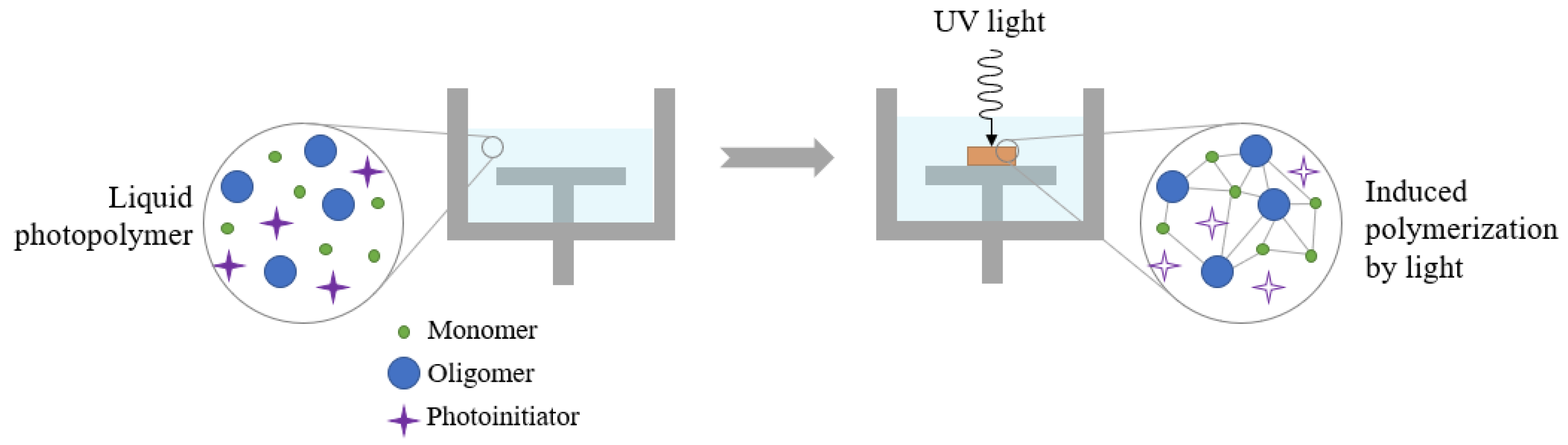
2.1. Components of Ceramic Resins

Raw resins are characterized by a solution of three main components: monomer, oligomer, and photo-initiator. In particular, photo-initiator (PI) can have two different natures: cationic or free-radical [20]. The nature of ceramic powder brings to require specific chemical properties of the different component used. The polarity of monomers/oligomers, PI type, diluent, and dispersant fraction, need correct evaluations. The principal categories of monomeric bases used for SLA resins are acrylates and epoxides. Distinctions between these two classes are being made in relation to chemical reactions in which they are involved. Acrylic monomers are characterized by a double carbon bond linked to a vinyl group; the polymerization starts when a free-radical PI reacts with a double bond. Epoxydic monomers react with a cationic PI, generating a chain reaction that brings to crosslinking. Acrylic and epoxy monomers are the bases of two macro-categories of resins, respectively aqueous and non-aqueous. Monomers are used not only to give particular characteristics to the final object, but also because of their diluent behavior [6,21]. Monomers and oligomers have got respectively a low and intermediate molecular weight and this parameter influence the final viscosity of the slurry. The polarity of the monomeric/oligomeric base has great importance for the correct dispersion of the solid phase [21]. Monomers and oligomers are unable to aggregate spontaneously, the role of PI is to accelerate this chemical reaction absorbing UV-light [6] (Figure 3).
There are two different ways to catalyze the reaction, in the function of the nature of PI [22]:
Free-radical PIs: when exposed to UV-light generates free radicals, which react breaking the double bond carbons (C=C) of a particular molecule of monomer/oligomer; unpaired carbons react with other molecules carbons, starting to generate a long-chain molecule. Macroscopically liquid resin polymerizes and evolve to solid state. This kind of reaction is typical for acrylate-methacrylate bases. Two main types of free-radical reactions are known, α -cleavage and H-abstraction. In α -cleavage mechanism double bond brakes and brings to formation of free radicals under the UV energy stimulation; instead, in H-abstraction photo-initiator reacts when stimulated by energy source with a second compound (a co-initiator) through hydrogen or electronical abstraction [20,21].
Cationic PIs: when exposed to UV-light generates Lewis or Bronsted acids through photolysis, which attack intra-molecule bond starting a re-aggregating chain reaction. This kind of phenomena take place with epoxy-based monomer. Lewis’s acids are generated when a diazonium salt are stimulated by an ultraviolet source and the anionic phase separate losing a halogen atom; the crosslinking starts when Lewis’s acids react with cycloaliphatic epoxides [23]. Bronsted acids are formed from different bases of salts, such as sulfur and phosphorous, compounds with an unshared pair of electrons. Typical onion salts which generate Bronsted acids are Iodonium and Sulfonium salt [24].
In general, although free-radical photo-initiators are more diffused in ceramic resins production because of their attitude with acrylic bases which are easier to use for a rheological motivation, cationic photo-initiators do not need an inert atmosphere, because there are no risks of process inhibition due to oxygen [24]. To give the ceramic resin a reduction in viscosity, thinners are used. These, in addition to giving the resin a low viscosity, contribute to the reduction of the refractive index (RI) [15]. Several diluents have been used in rather high fractions to ensure a significant reduction in viscosity. Hinczewski et al. [16] found that a 30 wt.% of thinner in an 80 wt.% alumina suspension leads to a three-fold reduction in viscosity compared to the viscosity of pure suspension without diluent. Diluents also help reduce the shrinkage of the polymeric phase, which is often cause by warping or delamination [25]. Unlike dispersing compounds, diluents are often low molecular weight monofunctional monomers, like 1,6-Hexanediol diacrylate (HDDA). Other diluents used are water, 1-Octanol, Glycerol, Polyethylene glycol (PEG)+ [15]. Dispersants are generally low volume, between 2–8% ceramic powder. The function of this kind of component is to avoid a rapid sedimentation of the solid suspension, favoring the mixing phase in a correct dispersion of the powder in solution. Another important role of dispersants is linked to the tendency of particles to agglomerate. This problem could generate various difficulties in the different phases of the process, from the covering of the vat during the passage between two successive layers to the atypical characterization of the internal porosity of the final part. The Wan der Waals attraction between particles increases with interparticle distance, the role of the dispersant is to reduce this attraction through an adsorption mechanism [15]. The most commonly used ceramics such as alumina, zirconia, silica, have a hydroxyl group on the surface of the particles which gives them a hydrophilic behavior that allows, based on the size of the particles, to agglomerate easily [13].

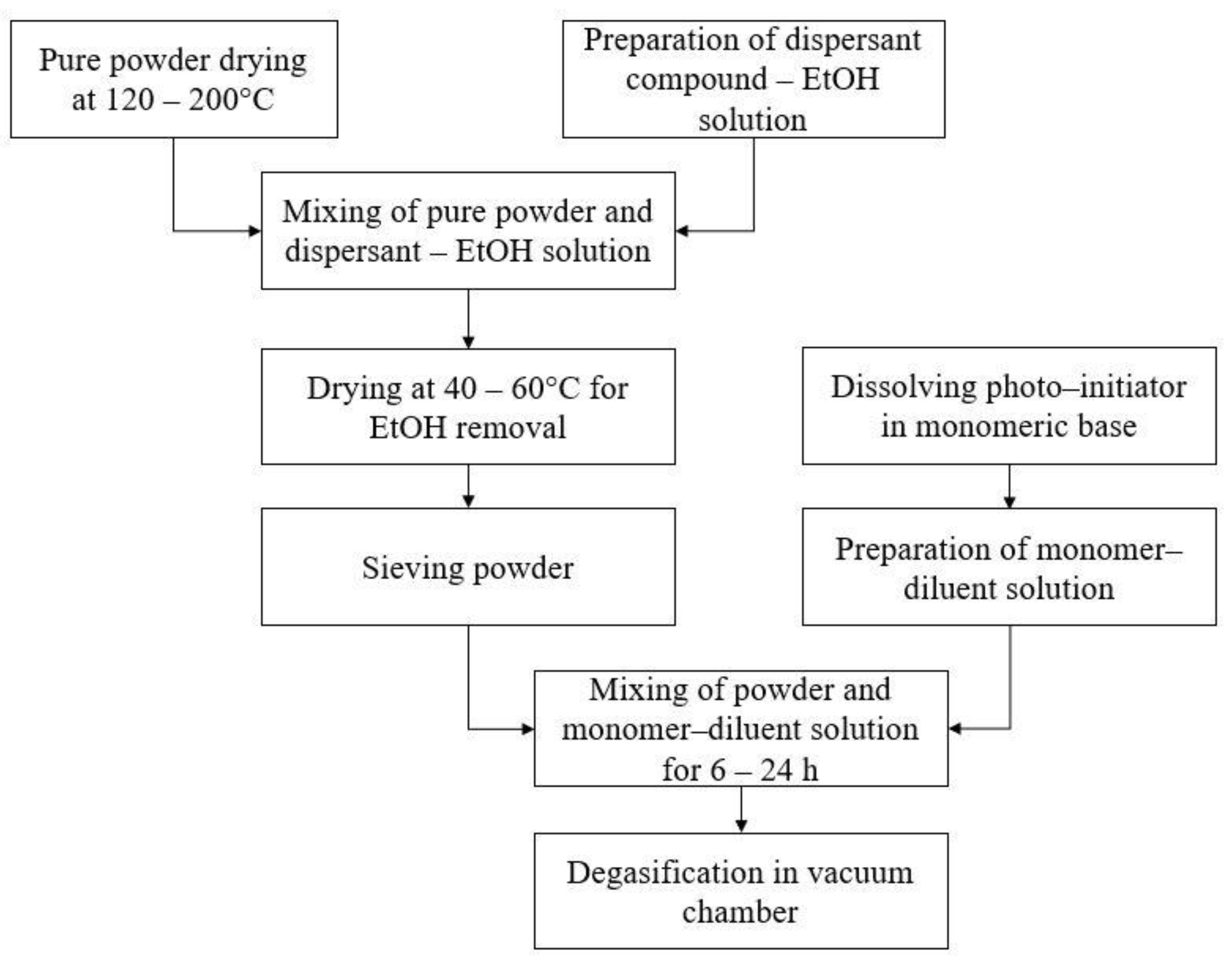
2.2. Ceramic Resin Preparation

Several studies report the preparation method for a ceramic suspension for SLA applications [17,18,26,27,28,29,30,31,32,33,34,35]. Although different parameters for processes as mixing or drying have been used a common line guide can be found. The first preparation phase is powder drying at temperature variable from 120 to 200 °C [26,34] for 6–10 h to remove all humidity residuals. A solution of dispersant and ethanol (EtOH) allows correct physisorption of dispersant to ceramic powder, through an ultrasonic mixing; successively a drying at 40–60 °C [18,27,32,33] allows to remove EtOH, which is a volatile compound. The correct dimension of ceramic particles is reached through sieving with a pre-selected mesh. Monomer and diluent ratio needs to be selected in relation to solid loading of suspension; a continuous stirring for 6–24 h [17,29,33,34] and a progressive addition of sieved powder allows to obtain final ceramic slurry. Final degasification in the vacuum chamber removes gas bubbles from suspension. Figure 4 resumes the suspension production process.

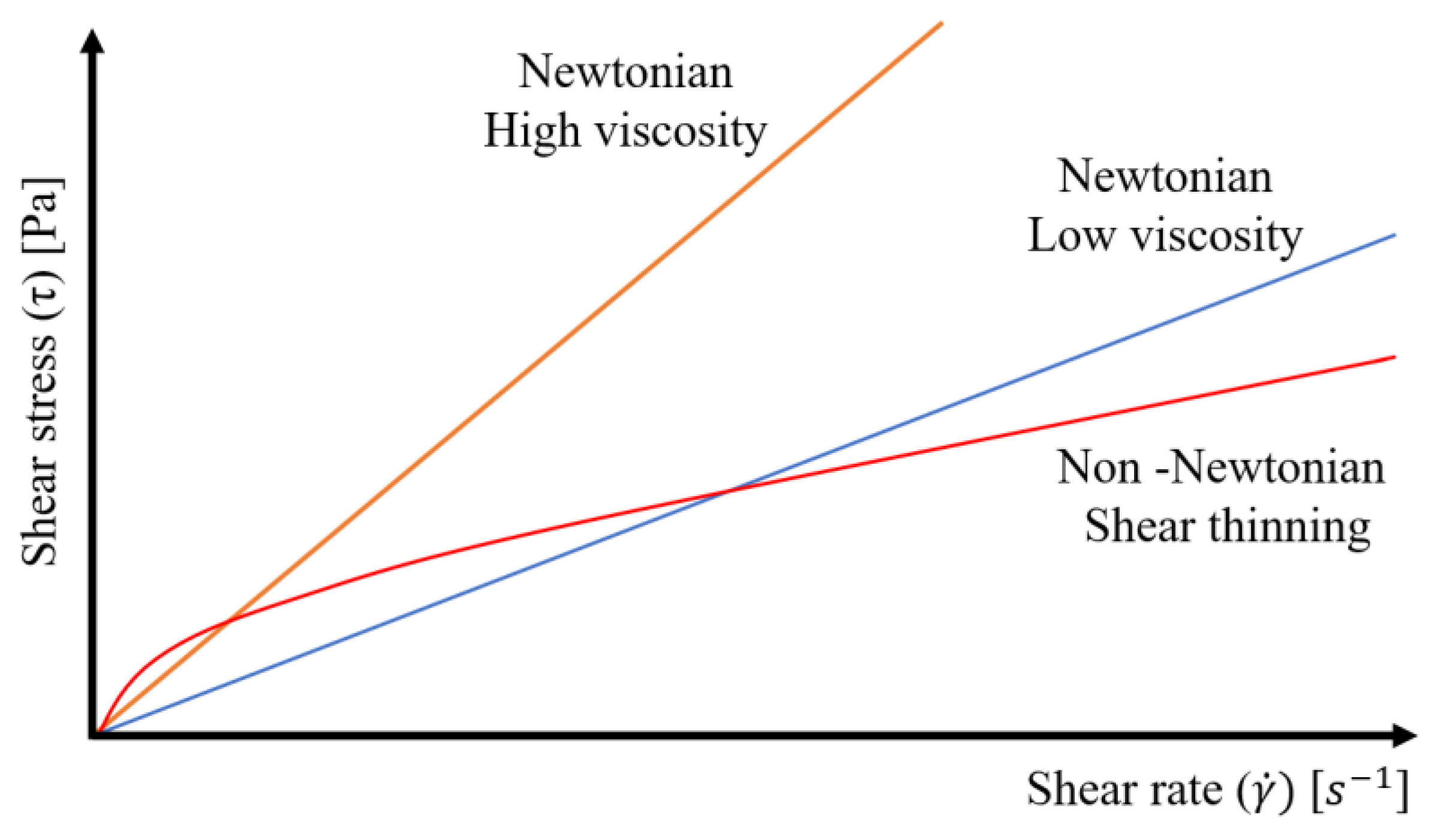
3. Rheological Behavior of Ceramic Suspension

Several studies report that low solid loading suspensions are characterized by a shear-thinning behavior [36,37,38], in contrast to high solid loading suspension, which shows a shear-thickening behavior [25]. In literature, non-Newtonian fluids are often analytically described by Herschel-Buckley’s model (Equation (1)):
τ = τ Y + K · γ ˙ n
where τ is the shear stress, τY is the yield stress of the material, K is the consistency index, and n is the flow index. Flow index value represents fluid behavior: n = 1 represents a Newtonian behavior, n < 1 represents a shear-thinning behavior, n > 1 represents a shear-thickening behavior (Figure 5). Shear-thinning behavior is preferable for ceramic suspension but for high solid loading suspension the need for compounds such as diluents and dispersants increase.
Several studies [39,40,41] show a transition value of shear rate, over which the behavior of the fluids transforms from shear-thinning to shear-thickening; this value is known in literature as γ ˙ c r . This transition value is reached more easily for higher solid loadings [15]. Colloidal suspensions with high solid loading are often viscoelastic fluids, characterized by a combined behavior between elastic responses to applied stresses and a pure viscous flow. Viscoelastic characterization can be made through a sequence of dynamic oscillatory measurements, with the purpose to find the stored/dissipated energy fraction through an evaluation of the strain-stress feature [42]. Thixotropy is a property of some non-Newtonian fluids, consisting of a variety of viscosity at a given shear rate over time; a recovery of the original value of viscosity is reached when flow ceases. Evaluating experiment of thixotropic behavior is reported by Goswami et al. [18]: they measured apparent viscosity of the ceramic suspensions in the condition of upward and downward shear rate sweep. In a shear rate variation cycle, quick restoration of apparent viscosity denotes good stability of a suspension, and in general, the difference between the upward cycle’s viscosity and downward cycle’s viscosity at a given shear rate can be measured to evaluate the predominance of thixotropic behavior. A suspension is stable when the dispersion mechanism of the particles is efficient enough to limit or to avoid completely flocculence, slowing down the sedimentation of solid parts. In SLA applications ceramic suspensions need to be as stable as possible, to avoid differences in mechanical properties of components having long process time. Solutions with a low solid fraction (φ < 1 vol.%) are in the Stokes’ law validity field, according to which a single particle immersed in a fluid undergoes actions of viscosity and gravity at the same time. Stokes’ law has been even manipulated for suspension with high solid fractions, but his validity for colloidal suspension is not anyhow guaranteed [43]. Gravitational actions are more negligible for colloidal suspensions as finer the particles are; this situation is described by Brownian’s motion, according to which viscosity is the main action on suspended particles. Brownian motion, diffusion, and other phenomena favor the aggregation of particles, the creation of large particles, and sedimentation [15]. Dispersants have an important role not only for rheological motivation but also in guaranteeing the stability of the suspension. In particular, through an adsorption mechanism, dispersants generate a series of hydrophobic chains around particles, which contrast themselves avoiding aggregations. Evaluation of the stability of suspensions can be made by measuring the level of a sedimented part after a long period of stasis [41,44].

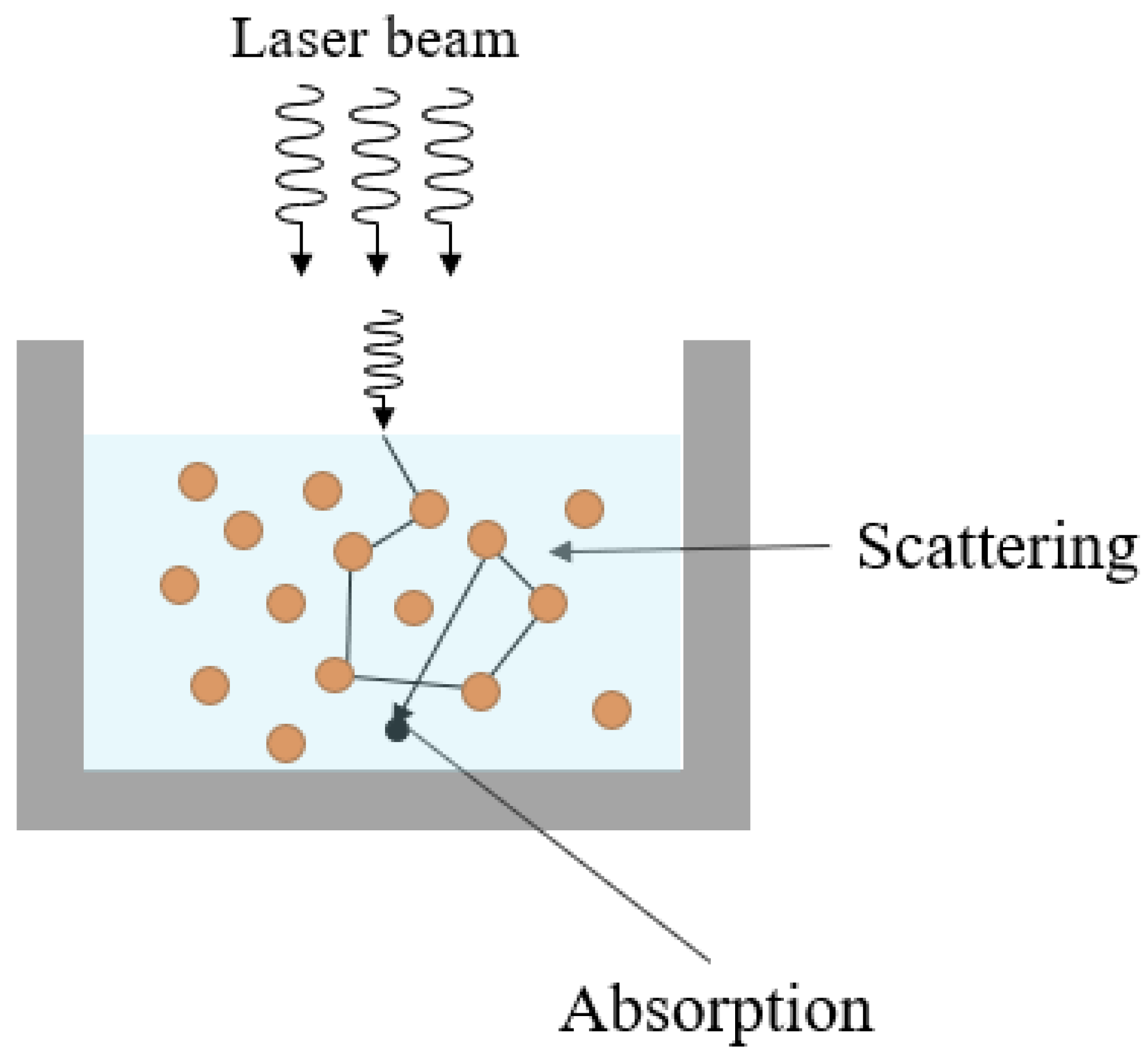
4. Ceramic Suspensions and Effects on the Process

Effects of suspension’s solid loading influence several aspects of the process. Primarily parameters such as yield stress or flow index change, rheological behavior is predominantly influenced by the number of solid particles in suspension. In ceramic suspension for SLA, maximum solid loading possible is often desired for different reasons, from the ease of green parts post-process to a more controllable shrinkage effect. Krieger-Dougherty analytical formulation is frequently used to obtain a model for relative viscosity (ηr) of suspensions (Equation (2)):
η r = η s η d = ( 1 ϕ ϕ m ) B · ϕ m
where ηs and ηd are respectively viscosity of suspension and dispersion medium, ϕ is the solid loading of suspension, ϕm is the maximum solid loading obtainable, B is the Einstein coefficient. B and ϕm depend on the shape and size of particles, so a fit model to determine them is necessary [17,26]. In literature, differences between Krieger-Dougherty model and experimental data are quite low, demonstrating a good reliable of analytical formulation. Several studies confirm a raise of relative viscosity with solid loading incrementation, in addition to a deviation from Newtonian behavior [13,18,19,26,28,44,45].
It is well known that particle size in ceramic suspensions is one of the most influential aspects of fluid behavior and optical characterization. Larger particles are more difficult to disperse in monomeric base than finer ones, it is due to a lower surface energy (lower specific surface). Previously, the effect of particle size on suspension’s stability has been investigated: Wan der Waals interactions and Brownian’s motion cause an agglomeration of particles as finer they are. Ding et al. [46] studied effects of nanoparticles (40 nm) addition to micro-particles (15 µm) silicon carbide (SiC) suspension, an interesting result has been found. The viscosity of suspensions is heavily influenced by nano-particles addition, while curing thickness showed a decrease. The influence of nano-particles addition on stability of suspension is one of the most interesting aspects, because experimental tests on sedimentation behavior showed a positive effect. Nanoparticles are arranged in the interstices of micro-particles, making agglomeration, and consequently sedimentation, more difficult. The creation of bimodal suspensions has a positive effect also in delaying shear thickening behavior [47].
When a light source hits an object, different optical phenomena take place. The scattering effect (Figure 6) is usually matched with absorption in energy transformation of the source, competing for the attenuation light beam [48].
Optical phenomena in which SLA ceramic suspensions are involved depend on different aspects: solid loading, particle size, RI of particle, RI of the medium, PIs and dyes percentage, energy dose. The scattering effect occurs every time a solid particle dispersed in a medium deviates a beam. A common approach is to consider the scattering coefficient which quantifies the decrease of penetration depth (Dp) due to light deviation of particles. The absorption model introduced by Tomeckova and Halloran [50] considers the two different contribute of scattering effect and absorption in evaluating the reciprocal of Dp (Equation (3)):
1 D p = S + A ϕ · A = A d
where S is the scattering coefficient, which depends on particles size and distribution, the difference between medium RI and particles RI. This coefficient is the reciprocal of scattering length, which is defined as the dimensional value over which photon propagation becomes randomized [51]. ϕ is the volume fraction of ceramic, A is the absorption coefficient, which depends on the concentration and molar extinction coefficient of inert dyes and PIs (or other non-inert optical compounds), and Ad is the attenuation coefficient. In highly dispersed ceramic suspensions scattering effect has a great impact in deviation of light direction, modifying cure depth and penetration depth in relation to the square difference between RI of particles and medium Δ n 2 = ( n p n d ) 2 [52]. Many powders are characterized by a high value of RI, so they have a short scattering length; combination with modified mediums with a higher refractive index is practically advantageous. However, refractive indexes are not constant in all spectrums of wavelengths, so a correct evaluation through spectrophotometry of materials allows establishing the real RI contrast in a specific stereolithographic application. Huang et al. [53] studied optical behavior of Si3N4 powders after oxidation at different temperatures; oxidation leads to a decrease of RI of particles through forming of amorphous phases, so a minor RI contrast with the medium is obtained. Table 1 reports RIs and RIs contrast with the medium of slurries prepared for some studies available in the literature.
Known scattering theories such as Rayleigh-Gans or Mie are based on the assumption that scattering takes place in very dilute suspensions, so they are not applicable to high solid loading ceramic suspensions for stereolithographic applications. Variability of the phenomenon, due to different aspects, makes analytical treatments difficult, so a semi-empirical method is preferable [54,59]. Gentry et al. [60] investigated variation in polymerization geometry due to scattering and absorption effect. They found that the application of parameters as critical energy dose and attenuation factor in each direction to quasi Beer-Lambert law leads to a correct evaluation of cure depth and cure width. Critical energy dose is not influenced by volume fraction or in general by scattering effect, while the geometry of absorbing area is strongly influenced by RI contrast and incident energy dose.
From the point of view of optical characterization, particle size is one of the most important aspects which needs to be evaluated. Larger particles are involved in a less frequent deviation of the light beam, scattering coefficient is consequently lower, cure depth increases. Small particles, instead, cause a higher horizontal broadening in penetration shape, removing suitable energy to vertical penetration. Ding et al. [61] demonstrated this behavior by curing a ceramic suspension of SiC powder with different particle sizes suspended in a hexanediol diacrylate (HDDA) base and measuring the resulting cure depth. Absorbance value increase with particle size, a reduction in inter-particle size leads promote an easier absorption of UV wavelengths [62]. Deviation of light beams in polymerization causes an increase in the horizontal amplitude of energy distribution, consequently, the cure width in case of scattering effect is larger than that without scattering. The curing profile of raw resins is narrow, while in ceramic suspensions broadening profile occurs. Cure depth suffers a decrease for a series of losses in energy, due to light scattering or absorbing. One of the first consequences in cure with increase is the loss of dimensional accuracy, precision scanning techniques are insufficient to ensure a good quality of polymerization. Modification of particles size, solid loading or energy dose, PI’s and/or dye’s concentration [63], are some of the possible ways to improve final part quality. Cure width can have a greater entity than laser beam radius as shown in Figure 7. Several studies demonstrated this relation measuring cure depth reached when different energy doses are impressed to slurries with different particle sizes [34,35,51,59,62,63,64]. Variation of energy dose is not interesting only for cure depth modification, but even for the particular behavior on horizontal plane.

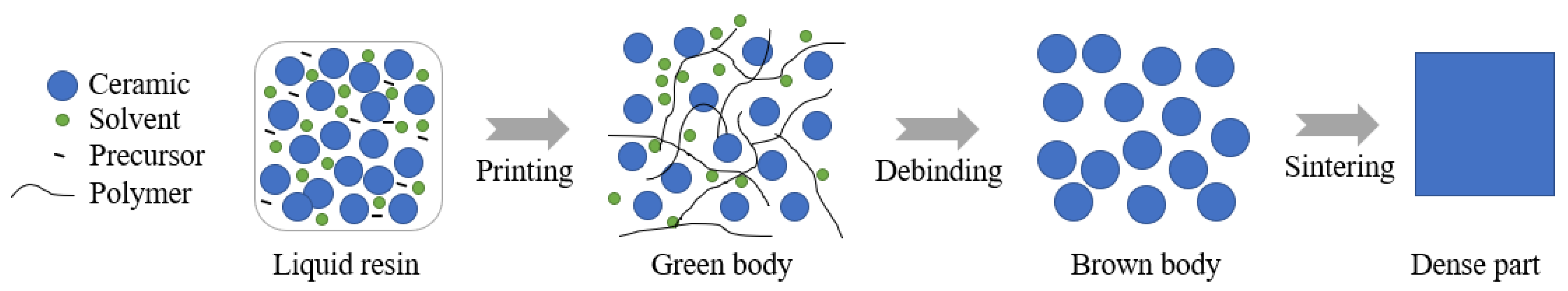
5. Post-Processing of Ceramic Green Parts

Post-processing is one of the most critical steps of ceramic stereolithography production. Different materials, solid loadings, or particle sizes give to post-processing a variability that needs a careful evaluation, from the fragility of green parts in support removal to the final shrinkage, porosity, and defects of the sintered part. Green parts are defined as the polymerized object characterized by a mixture of the polymeric base and ceramic in solid suspension trapped in a polymeric matrix. Removing objects from the building platform is often a complicated step, in reason of the fragility of the green part. Optimization of parts positioning on building platform and the addition of a separate interface between supports and building platform simplifies this delicate operation. Supports removal could even cause defects on the object’s surface, but the positioning of them can be evaluated: if the object contains surfaces on which dimensional precision is not required and they are in a good position to support effectively the object, supports can be positioned on these surfaces. Otherwise, a further finishing phase is necessary in order to guarantee a correct dimensional precision of the part. The most important steps of post-processing of ceramic green parts are debinding, through which polymeric binder is removed, and sintering, a high-temperature treatment that confers to ceramic object better mechanical properties (Figure 8).

5.1. Debinding

The debinding process has the function to remove polymer binder from the green body, leading to obtainment of a ceramic component with poor mechanical properties, high internal porosity, and low density. It is characterized by an environmental atmosphere of full argon [66], air [67], or vacuum [33]. Some studies [31,68,69] used a hybrid debinding process, characterized by vacuum debinding at first, which guarantees an easier control of temperature rate and evacuation of organic fumes, an air debinding subsequently. The atmosphere of the process influences different features of the objects, from microstructural and mechanical properties to physical behavior. Li et al. [70] compared these effects on alumina samples processed under vacuum, argon, and air atmosphere. The characterization has shown that debinding in air leads to a better mechanical behavior, while microstructure showed differences compared to the samples treated in an argon atmosphere or under vacuum. This is probably due to the thermodynamical processes which take place during the organic decomposition: exothermic reactions occurred under air atmosphere, endothermic reactions under vacuum, and argon atmospheres. Wu et al. [33] demonstrated the increase of relative density in samples treated with debinding in vacuum atmosphere, with respect to samples processed with air atmosphere.

5.2. Sintering

Being a post-treatment shared between the most common ceramic manufacturing processes, sintering has the purpose to improve the mechanical properties and microstructure of the object set free from the polymeric binder. As in debinding treatments happens, even in sintering, the final object is characterized by a volumetric shrinkage quite pronounced, but being a not fully controlled process, anisotropies in shrinkage can arise [71]. Different from debinding, during sintering treatment there is not a decomposition of an organic phase, consequently, no issues in relation to evacuation of fumes from the core of the object occur and the temperature rate can be higher in respect to debinding process. Even in sintering working atmosphere and temperature influence mechanical properties and microstructure of components. Li et al. [72] investigated the variation of mechanical and microstructural behavior of alumina 3D-printed samples, in relation to the raise of sintering temperature under argon atmosphere. Mechanical properties increased with sintering temperature, while the microstructure of alumina samples showed different interesting results. Internal pores present in all investigated samples are due to fumes evacuation typical of debinding process, while the average grain size raises with process temperature according to the diffusion mechanism which triggers. Another aspect that needs attention is the increase of interlayer spacing with sintering temperature, which is linked to volumetric shrinkage and can constitute an important issue if combined with internal delamination in terms of mechanical resistance. Delamination phenomena can be reduced with temperature rate in debinding and sintering processes, but it is impossible to eliminate completely.

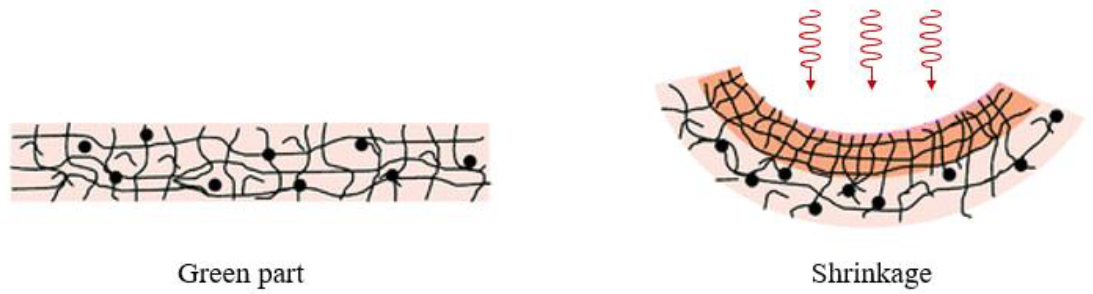
6. Effects of Post-Processing on Geometrical, Physical and Mechanical Properties

6.1. Volume Shrinkage and Interlayer Spacing

A major part of ceramic manufacturing technologies is distinguished for the characterization of volumetric shrinkage, but not all of them lead to the loss of a polymeric binder. In SLA applications the maximum value of ceramic powder in proportion to the monomeric base is wished, in reason to minimize as possible the post-treatment volumetric shrinkage. Warping effects can occur during post-curing and thermal post-treatment (Figure 9).
Geometric and dimensional quality of a manufacturing process is evaluated in function of the respect of requirement also considering the post-treatment needed. Consequently, a correct evaluation of the shrinkage in the three different axes is useful to provide characterization and to have as possible complete knowledge of the accuracy of the full manufacturing process. Anisotropies generated from volumetric shrinkage and delamination derived from pyrolysis are two of the main factors which concurs to modify the space between layers. Li et al. [74] investigated the behavior of interlayer spacing in relation to the temperature reached in the sintering process. The first decrease of interlayer space influenced by previous volatilization of polymeric binder is followed by an increase probably due to the predominant impact of shrinkage with the rise of temperature. Pan et al. [75] highlighted the decreasing trend of the interlayer spacing due to the increase of sintering holding time, demonstrating the importance of this parameter in promoting adhesion between layers.

6.2. Dimensional Accuracy for Ceramic Resins

One of the most important aspects from a technological point of view is the dimensional accuracy of the complete process. SLA process gives usually good dimensional accuracy, but post-processing causes the loss of the polymeric binder, and consequently, volumetric shrinkage leads to an uncertainty in the final dimension of printed parts. Different aspects can influence the proportion of volumetric loss. Debinding and sintering phases give rise to volumetric shrinkage but each for different physical reasons. In debinding treatment, shrinkage is the consequence of the mass loss due to decomposition of polymeric binder, so it can be expected a range of dimensional value for the final parts through an evaluation of powder fraction. In the sintering phase, other aspects influence the volumetric shrinkage occurring, such as the medium size of powder particles or final temperature, and anisotropies are often expected [76]. Correlation between particle size and maximum sintering temperature is important for the physical behavior of diffusion phenomena triggered in thermal treatment [77]. Zhang et al. [78] showed that fine particles and sintering additives combined in the resin mixture cause an increase of volumetric shrinkage. Table 2 reports the values of volumetric shrinkage for different materials used for SLA applications.
In Zirconia resins high solid loadings are usually heavy to obtain, not only for the optical compatibility with the monomeric mixture but also for rheological reasons. Consequently, dimensional shrinkage in the range of 18–36% is expected for relatively high solid loadings and particle sizes typical for stabilized powders. Alumina resins allow a wider range of solid loadings, thanks to a better rheological and optical compatibility with the organic phase, but usually high solid loadings are preferred in order to reduce probability in crack formation during post-treatment.

6.3. Bulk Density and Mechanical Properties

Sintering temperature influences the physical properties of ceramic components, first of all, bulk density and porosity. Chi et al. [89] demonstrated that porosity decrease with sintering temperature increase; this behavior is due to lowering of viscosity of liquid phases, which fill empty pores and confer a higher density to the component. Different liquid phases with different physical properties are generated in relation to the sintering temperature and holding time. Consequently, also mean pore size decreases with sintering temperature [90]. As a consequence of the increasing bulk density and decreasing of porosity, flexural strength and hardness increase with sintering temperature and holding time. Reduction of interlayer spacing improves the mechanical strength of components, and it can be reached in a sufficiently high range of sintering temperature [74]. An et al. [79] compared the hardness and microhardness of ceramic compounds manufactured with additive technologies and with traditional manufacturing methods. The hardness of ceramics obtained through additive manufacturing technologies seems to be higher in respect to hardness obtained with other traditional technologies. Another important aspect of mechanical characterization of ceramic manufacturing is the creep resistance: creep deformation decreases with sintering temperature increase [91], giving to material a better thermal-stress resistance.

7. Ceramic Resins Commercially Available

Nowadays a lot of ceramic resin for stereolithography applications are available. The preparation of ceramic suspensions requires a high level of knowledge, as well as specific instruments. For specific fields of industry and research, such as process details investigations, or educational fields, commercial resins offer a good opportunity in terms of costs, time and skills required. Green body obtained by stereolithography processes are ceramic-polymer composites, with physical and mechanical behaviors which can be interesting to investigate. In Table 3 some examples of ceramic resins commercially available and their main applications fields are reported.
But in usage of commercial resins, one of the first issues is the compatibility between resin and the optical system used. Unknowledge of the exact nature of chemical compounds does not allow to ensure good feasibility of process, because the wavelength of the light source could be not perfectly compatible. Another problem is the unavailability of suspension solid loading on commercial datasheets, bringing two main consequences. First, it is not predictable whether the printer used can manage resin with unknown viscosity, issues in layers recoating can occur. Secondly, the probability of cracks formation in post-processing increases when percentages of mass losses in specific temperature ranges during debinding are uncertain. Usage of commercial resins in experimental studies should be matched to previous material analyses, in order to predict behavior in the different steps of production process, such as rheological measurements, stability evaluations, thermal analysis, and study on granulometry.

8. Conclusions

In this review, various aspects of the stereolithography process have been studied to highlight the peculiarities that make it ideal for the production of ceramic components. Unlike classic SLA applications, in ceramic stereolithography the basic materials are non-Newtonian fluids, therefore a previous characterization of the resins, in terms of stability, thixotropy, shear thickening-thinning behavior, allows to avoid various problems that could occur during production, such as agglomeration or viscosity increase. Extinction phenomena were presented in terms of dimensional quality and geometric precision, in particular, the importance of the difference RI between ceramic powder and monomer base was explained. In ceramic manufacturing technologies, post-treatment often includes debinding and sintering processes. The removal of the binder is the most critical step of the post-treatment, due to defects or delamination that could be generated during the evacuation of the polymer units. Sintering gives mechanical consistency to components, reducing internal and external porosity and increasing the density of parts. The solid loading of a resin base and the post-treatment processes are closely related, it is necessary to study the volumetric shrinkage of the final parts, in order to guarantee a free cracking component. Preparation of powder suspensions can be considered a great advantage in terms of arrangement between the geometrical capability of stereolithography processes and the obtainment of components with good mechanical or physical properties, not only for ceramic components, but also for bio-compatible materials and metals. Usage of different powder materials can open ceramic production fields to new borders of industry. An important aspect that needs to be investigated is how to make this kind of technology more sustainable, starting from chemical compounds used for resin preparation, until the analysis of the environmental impact of post-processing operations.

Author Contributions

Conceptualization, A.B., F.C.; Investigation, A.B.; Methodology, A.B., F.C., M.G.; Supervision, F.C., M.G., L.I.; Validation, F.C.; Writing—original draft, A.B., F.C. All authors have read and agreed to the published version of the manuscript.

Funding

This research received no external funding.

Institutional Review Board Statement

Not applicable.

Informed Consent Statement

Not applicable.

Data Availability Statement

Not applicable.

Conflicts of Interest

The authors declare no conflict of interest.

References

  1. Wilkes, J.; Hagedorn, Y.C.; Meiners, W.; Wissenbach, K. Additive Manufacturing of ZrO2-Al2O3 Ceramic Components by Selective Laser Melting. Rapid Prototyp. J. 2013, 19, 51–57. [Google Scholar] [CrossRef]
  2. Gadow, R.; Kern, F. Pressureless Sintering of Injection Molded Zirconia Toughened Alumina Nanocomposites. J. Ceram. Soc. Jpn. 2006, 114, 958–962. [Google Scholar] [CrossRef] [Green Version]
  3. Liu, Z.; Wang, Y.; Wu, B.; Cui, C.; Guo, Y.; Yan, C. A Critical Review of Fused Deposition Modeling 3D Printing Technology in Manufacturing Polylactic Acid Parts. Int. J. Adv. Manuf. Technol. 2019, 102, 2877–2889. [Google Scholar] [CrossRef]
  4. Vaezi, M.; Seitz, H.; Yang, S. A Review on 3D Micro-Additive Manufacturing Technologies. Int. J. Adv. Manuf. Technol. 2013, 67, 1721–1754. [Google Scholar] [CrossRef]
  5. Melchels, F.P.W.; Feijen, J.; Grijpma, D.W. A Review on Stereolithography and Its Applications in Biomedical Engineering. Biomaterials 2010, 31, 6121–6130. [Google Scholar] [CrossRef] [Green Version]
  6. Zakeri, S.; Vippola, M.; Levänen, E. A Comprehensive Review of the Photopolymerization of Ceramic Resins Used in Stereolithography. Addit. Manuf. 2020, 35, 101177. [Google Scholar] [CrossRef]
  7. Chen, A.N.; Chen, J.Y.; Wu, J.M.; Cheng, L.J.; Liu, R.Z.; Liu, J.; Chen, Y.; Li, C.H.; Wen, S.F.; Shi, Y.S. Porous Mullite Ceramics with Enhanced Mechanical Properties Prepared by SLS Using MnO2 and Phenolic Resin Coated Double-Shell Powders. Ceram. Int. 2019, 45, 21136–21143. [Google Scholar] [CrossRef]
  8. Mahesh, M.; Wong, Y.S.; Fuh, J.Y.H.; Loh, H.T. Benchmarking for Comparative Evaluation of RP Systems and Processes. Rapid Prototyp. J. 2004, 10, 123–135. [Google Scholar] [CrossRef]
  9. Griffith, M.L.; Halloran, J.W. Ultraviolet Curing of Highly Loaded Ceramic Suspensions for Stereolithography of Ceramics. Solid Free. Fabr. Symp. 1994, 396–403. [Google Scholar]
  10. Gao, Y.; Ding, J. Low Solid Loading, Low Viscosity, High Uniform Shrinkage Ceramic Resin for Stereolithography Based Additive Manufacturing. Procedia Manuf. 2020, 48, 749–754. [Google Scholar] [CrossRef]
  11. Ye, H.; Das, S.; Zhou, C. Investigation of Separation Force for Bottom-up Stereolithography Process from Mechanics Perspective. In Proceedings of the ASME Design Engineering Technical Conference, Boston, MA, USA, 2–5 August 2015. [Google Scholar]
  12. Griffith, M.L.; Halloran, J.W. Freeform Fabrication of Ceramics via Stereolithography. J. Am. Ceram. Soc. 2005, 79, 2601–2608. [Google Scholar] [CrossRef] [Green Version]
  13. Sun, J.; Binner, J.; Bai, J. Effect of Surface Treatment on the Dispersion of Nano Zirconia Particles in Non-Aqueous Suspensions for Stereolithography. J. Eur. Ceram. Soc. 2019, 39, 1660–1667. [Google Scholar] [CrossRef]
  14. Xu, X.; Zhou, S.; Wu, J.; Zhang, C.; Liu, X. Inter-Particle Interactions of Alumina Powders in UV-Curable Suspensions for DLP Stereolithography and Its Effect on Rheology, Solid Loading, and Self-Leveling Behavior. J. Eur. Ceram. Soc. 2021, 41, 2763–2774. [Google Scholar] [CrossRef]
  15. Camargo, I.L.; de Morais, M.M.; Fortulan, C.A.; Branciforti, M.C. A Review on the Rheological Behavior and Formulations of Ceramic Suspensions for Vat Photopolymerization. Ceram. Int. 2021, 47, 11906–11921. [Google Scholar] [CrossRef]
  16. Hinczewski, C.; Corbel, S.; Chartier, T. Ceramic Suspensions Suitable for Stereolithography. J. Eur. Ceram. Soc. 1998, 18, 583–590. [Google Scholar] [CrossRef]
  17. Brady, G.A.; Halloran, J.W. Differential Photo-Calorimetry of Photopolymerizable Ceramic Suspensions. J. Mater. Sci. 1998, 33, 4551–4560. [Google Scholar] [CrossRef]
  18. Goswami, A.; Ankit, K.; Balashanmugam, N.; Umarji, A.M.; Madras, G. Optimization of Rheological Properties of Photopolymerizable Alumina Suspensions for Ceramic Microstereolithography. Ceram. Int. 2014, 40, 3655–3665. [Google Scholar] [CrossRef]
  19. Zhang, K.; He, R.; Xie, C.; Wang, G.; Ding, G.; Wang, M.; Song, W.; Fang, D. Photosensitive ZrO2 Suspensions for Stereolithography. Ceram. Int. 2019, 45, 12189–12195. [Google Scholar] [CrossRef]
  20. Koleske, J. Free-Radical Photoinitiators and Initiation Mechanism. In Radiation Curing of Coatings; ASTM International: West Conshohocken, PA, USA, 2008; Chapter 3. [Google Scholar]
  21. Manapat, J.Z.; Chen, Q.; Ye, P.; Advincula, R.C. 3D Printing of Polymer Nanocomposites via Stereolithography. Macromol. Mater. Eng. 2017, 302, 1600553. [Google Scholar] [CrossRef]
  22. Lalevée, J.; Blanchard, N.; Tehfe, M.A.; Peter, M.; Morlet-Savary, F.; Gigmes, D.; Fouassier, J.P. Efficient Dual Radical/Cationic Photoinitiator under Visible Light: A New Concept. Polym. Chem. 2011, 2, 1986–1991. [Google Scholar] [CrossRef]
  23. Koleske, J. Cationic Photoinitiators and Initiation Mechanism. In Radiation Curing of Coatings; ASTM International: West Conshohocken, PA, USA, 2008; Chapter 4. [Google Scholar]
  24. Koleske, J.V. Radiation Curing of Coatings. In Paint and Coatings Industry; ASTM International: West Conshohocken, PA, USA, 2002. [Google Scholar]
  25. Johansson, E.; Lidström, O.; Johansson, J.; Lyckfeldt, O.; Adolfsson, E. Influence of Resin Composition on the Defect Formation in Alumina Manufactured by Stereolithography. Materials 2017, 10, 138. [Google Scholar] [CrossRef] [Green Version]
  26. Zhang, S.; Sha, N.; Zhao, Z. Surface Modification of α-Al2O3 with Dicarboxylic Acids for the Preparation of UV-Curable Ceramic Suspensions. J. Eur. Ceram. Soc. 2017, 37, 1607–1616. [Google Scholar] [CrossRef]
  27. Wu, X.; Lian, Q.; Li, D.; He, X.; Meng, J.; Liu, X.; Jin, Z. Influence of Boundary Masks on Dimensions and Surface Roughness Using Segmented Exposure in Ceramic 3D Printing. Ceram. Int. 2019, 45, 3687–3697. [Google Scholar] [CrossRef]
  28. Jang, K.J.; Kang, J.H.; Fisher, J.G.; Park, S.W. Effect of the Volume Fraction of Zirconia Suspensions on the Microstructure and Physical Properties of Products Produced by Additive Manufacturing. Dent. Mater. 2019, 35, e97–e106. [Google Scholar] [CrossRef]
  29. Li, X.; Hu, K.; Lu, Z. Effect of Light Attenuation on Polymerization of Ceramic Suspensions for Stereolithography. J. Eur. Ceram. Soc. 2019, 39, 2503–2509. [Google Scholar] [CrossRef]
  30. Chartier, T.; Badev, A.; Abouliatim, Y.; Lebaudy, P.; Lecamp, L. Stereolithography Process: Influence of the Rheology of Silica Suspensions and of the Medium on Polymerization Kinetics—Cured Depth and Width. J. Eur. Ceram. Soc. 2012, 32, 1625–1634. [Google Scholar] [CrossRef]
  31. Zhou, M.; Liu, W.; Wu, H.; Song, X.; Chen, Y.; Cheng, L.; He, F.; Chen, S.; Wu, S. Preparation of a Defect-Free Alumina Cutting Tool via Additive Manufacturing Based on Stereolithography—Optimization of the Drying and Debinding Processes. Ceram. Int. 2016, 42, 11598–11602. [Google Scholar] [CrossRef]
  32. Badev, A.; Abouliatim, Y.; Chartier, T.; Lecamp, L.; Lebaudy, P.; Chaput, C.; Delage, C. Photopolymerization Kinetics of a Polyether Acrylate in the Presence of Ceramic Fillers Used in Stereolithography. J. Photochem. Photobiol. A Chem. 2011, 222, 117–122. [Google Scholar] [CrossRef]
  33. Wu, H.; Cheng, Y.; Liu, W.; He, R.; Zhou, M.; Wu, S.; Song, X.; Chen, Y. Effect of the Particle Size and the Debinding Process on the Density of Alumina Ceramics Fabricated by 3D Printing Based on Stereolithography. Ceram. Int. 2016, 42, 17290–17294. [Google Scholar] [CrossRef]
  34. Hu, K.; Wei, Y.; Lu, Z.; Wan, L.; Li, P. Design of a Shaping System for Stereolithography with High Solid Loading Ceramic Suspensions. 3D Print. Addit. Manuf. 2018, 5, 311–318. [Google Scholar] [CrossRef]
  35. Chartier, T.; Chaput, C.; Doreau, F.; Loiseau, M. Stereolithography of Structural Complex Ceramic Parts. J. Mater. Sci. 2002, 37, 3141–3147. [Google Scholar] [CrossRef]
  36. Komissarenko, D.A.; Sokolov, P.S.; Evstigneeva, A.D.; Shmeleva, I.A.; Dosovitsky, A.E. Rheological and Curing Behavior of Acrylate-Based Suspensions for the DLP 3D Printing of Complex Zirconia Parts. Materials 2018, 11, 2350. [Google Scholar] [CrossRef] [Green Version]
  37. Xing, H.; Zou, B.; Liu, X.; Wang, X.; Chen, Q.; Fu, X.; Li, Y. Effect of Particle Size Distribution on the Preparation of ZTA Ceramic Paste Applying for Stereolithography 3D Printing. Powder Technol. 2020, 359, 314–322. [Google Scholar] [CrossRef]
  38. Wei, L.; Zhang, J.; Yu, F.; Zhang, W.; Meng, X.; Yang, N.; Liu, S. A Novel Fabrication of Yttria-Stabilized-Zirconia Dense Electrolyte for Solid Oxide Fuel Cells by 3D Printing Technique. Int. J. Hydrogen Energy 2019, 44, 6182–6191. [Google Scholar] [CrossRef]
  39. Bae, C.J.; Halloran, J.W. Concentrated Suspension-Based Additive Manufacturing—Viscosity, Packing Density, and Segregation. J. Eur. Ceram. Soc. 2019, 39, 4299–4306. [Google Scholar] [CrossRef]
  40. Borlaf, M.; Szubra, N.; Serra-Capdevila, A.; Kubiak, W.W.; Graule, T. Fabrication of ZrO2 and ATZ Materials via UV-LCM-DLP Additive Manufacturing Technology. J. Eur. Ceram. Soc. 2020, 40, 1574–1581. [Google Scholar] [CrossRef]
  41. Huang, X.; Dai, H.; Hu, Y.; Zhuang, P.; Shi, Z.; Ma, Y. Development of a High Solid Loading β-TCP Suspension with a Low Refractive Index Contrast for DLP -Based Ceramic Stereolithography. J. Eur. Ceram. Soc. 2021, 41, 3743–3754. [Google Scholar] [CrossRef]
  42. Lewis, J.A. Colloidal Processing of Ceramics. J. Am. Ceram. Soc. 2000, 83, 2341–2359. [Google Scholar] [CrossRef]
  43. Abel, J.S.; Stangle, G.C.; Schilling, C.H.; Aksay, I.A. Sedimentation in Flocculating Colloidal Suspensions. J. Mater. Res. 1994, 9, 451–461. [Google Scholar] [CrossRef] [Green Version]
  44. Zhang, K.; Xie, C.; Wang, G.; He, R.; Ding, G.; Wang, M.; Dai, D.; Fang, D. High Solid Loading, Low Viscosity Photosensitive Al2O3 Slurry for Stereolithography Based Additive Manufacturing. Ceram. Int. 2019, 45, 203–208. [Google Scholar] [CrossRef]
  45. Chen, Z.; Li, J.; Liu, C.; Liu, Y.; Zhu, J.; Lao, C. Preparation of High Solid Loading and Low Viscosity Ceramic Slurries for Photopolymerization-Based 3D Printing. Ceram. Int. 2019, 45, 11549–11557. [Google Scholar] [CrossRef]
  46. Ding, G.; He, R.; Zhang, K.; Xia, M.; Feng, C.; Fang, D. Dispersion and Stability of SiC Ceramic Slurry for Stereolithography. Ceram. Int. 2020, 46, 4720–4729. [Google Scholar] [CrossRef]
  47. Wozniak, M.; de Hazan, Y.; Graule, T.; Kata, D. Rheology of UV Curable Colloidal Silica Dispersions for Rapid Prototyping Applications. J. Eur. Ceram. Soc. 2011, 31, 2221–2229. [Google Scholar] [CrossRef]
  48. Huber, E.; Frost, M. Light Scattering by Small Particles. J. Water Supply Res. Technol. AQUA 1998, 47, 87–94. [Google Scholar] [CrossRef]
  49. Delhote, N.; Bila, S.; Baillargeat, D.; Chartier, T.; Verdeyme, S. Advanced Design and Fabrication of Microwave Components Based on Shape Optimization and 3D Ceramic Stereolithography Process. In Advances in Ceramics—Synthesis and Characterization, Processing and Specific Applications; IntechOpen: London, UK, 2011; Available online: https://www.intechopen.com/chapters/17607 (accessed on 29 March 2022).
  50. Tomeckova, V.; Halloran, J.W. Cure Depth for Photopolymerization of Ceramic Suspensions. J. Eur. Ceram. Soc. 2010, 30, 3023–3033. [Google Scholar] [CrossRef]
  51. Gentry, S.P.; Halloran, J.W. Depth and Width of Cured Lines in Photopolymerizable Ceramic Suspensions. J. Eur. Ceram. Soc. 2013, 33, 1981–1988. [Google Scholar] [CrossRef]
  52. Griffith, M.L.; Halloran, J.W. Scattering of Ultraviolet Radiation in Turbid Suspensions. J. Appl. Phys. 1997, 81, 2538–2546. [Google Scholar] [CrossRef] [Green Version]
  53. Huang, R.J.; Jiang, Q.G.; Wu, H.D.; Li, Y.H.; Liu, W.Y.; Lu, X.X.; Wu, S.H. Fabrication of Complex Shaped Ceramic Parts with Surface-Oxidized Si3N4 Powder via Digital Light Processing Based Stereolithography Method. Ceram. Int. 2019, 45, 5158–5162. [Google Scholar] [CrossRef]
  54. Sun, C.; Zhang, X. The Influences of the Material Properties on Ceramic Micro-Stereolithography. Sens. Actuators A Phys. 2002, 101, 364–370. [Google Scholar] [CrossRef]
  55. Griffith, M.L.; Halloran, J.W. Stereolithography of Ceramics. Int. SAMPE Tech. Conf. 1995, 101, 364–370. [Google Scholar]
  56. Lian, Q.; Wu, X.; Li, D.; He, X.; Meng, J.; Liu, X.; Jin, Z. Accurate Printing of a Zirconia Molar Crown Bridge Using Three-Part Auxiliary Supports and Ceramic Mask Projection Stereolithography. Ceram. Int. 2019, 45, 18814–18822. [Google Scholar] [CrossRef]
  57. Altun, A.A.; Prochaska, T.; Konegger, T.; Schwentenwein, M. Dense, Strong, and Precise Silicon Nitride-Based Ceramic Parts by Lithography-Based Ceramic Manufacturing. Appl. Sci. 2020, 10, 996. [Google Scholar] [CrossRef] [Green Version]
  58. Jang, J.H.; Wang, S.; Pilgrim, S.M.; Schulze, W.A. Preparation and Characterization of Barium Titanate Suspensions for Stereolithography. J. Am. Ceram. Soc. 2000, 83, 1804–1806. [Google Scholar] [CrossRef]
  59. Tomeckova, V.; Halloran, J.W. Predictive Models for the Photopolymerization of Ceramic Suspensions. J. Eur. Ceram. Soc. 2010, 30, 2833–2840. [Google Scholar] [CrossRef]
  60. Gentry, S.P.; Halloran, J.W. Light Scattering in Absorbing Ceramic Suspensions: Effect on the Width and Depth of Photopolymerized Features. J. Eur. Ceram. Soc. 2015, 35, 1895–1904. [Google Scholar] [CrossRef]
  61. Ding, G.; He, R.; Zhang, K.; Xie, C.; Wang, M.; Yang, Y.; Fang, D. Stereolithography-Based Additive Manufacturing of Gray-Colored SiC Ceramic Green Body. J. Am. Ceram. Soc. 2019, 102, 7198–7209. [Google Scholar] [CrossRef]
  62. Liu, Y.; Zhan, L.; Wen, L.; Cheng, L.; He, Y.; Xu, B.; Wu, Q.; Liu, S. Effects of Particle Size and Color on Photocuring Performance of Si3N4 Ceramic Slurry by Stereolithography. J. Eur. Ceram. Soc. 2021, 41, 2386–2394. [Google Scholar] [CrossRef]
  63. Gentry, S.P.; Halloran, J.W. Absorption Effects in Photopolymerized Ceramic Suspensions. J. Eur. Ceram. Soc. 2013, 33, 1989–1994. [Google Scholar] [CrossRef]
  64. Wu, K.C.; Seefeldt, K.F.; Solomon, M.J.; Halloran, J.W. Prediction of Ceramic Stereolithography Resin Sensitivity from Theory and Measurement of Diffusive Photon Transport. J. Appl. Phys. 2005, 98, 024902. [Google Scholar] [CrossRef] [Green Version]
  65. Schmidleithner, C.; Kalaskar, M. Stereolitography. In 3D Printing; IntechOpen: London, UK, 2018; Available online: https://www.intechopen.com/chapters/61889 (accessed on 29 March 2022).
  66. Li, H.; Liu, Y.; Liu, Y.; Zeng, Q.; Hu, K.; Lu, Z.; Liang, J. Effect of Debinding Temperature under an Argon Atmosphere on the Microstructure and Properties of 3D-Printed Alumina Ceramics. Mater. Charact. 2020, 168, 110548. [Google Scholar] [CrossRef]
  67. Sun, J.; Binner, J.; Bai, J. 3D Printing of Zirconia via Digital Light Processing: Optimization of Slurry and Debinding Process. J. Eur. Ceram. Soc. 2020, 40, 5837–5844. [Google Scholar] [CrossRef]
  68. He, R.; Liu, W.; Wu, Z.; An, D.; Huang, M.; Wu, H.; Jiang, Q.; Ji, X.; Wu, S.; Xie, Z. Fabrication of Complex-Shaped Zirconia Ceramic Parts via a DLP- Stereolithography-Based 3D Printing Method. Ceram. Int. 2018, 44, 3412–3416. [Google Scholar] [CrossRef]
  69. Wu, Z.; Liu, W.; Wu, H.; Huang, R.; He, R.; Jiang, Q.; Chen, Y.; Ji, X.; Tian, Z.; Wu, S. Research into the Mechanical Properties, Sintering Mechanism and Microstructure Evolution of Al2O3-ZrO2 Composites Fabricated by a Stereolithography-Based 3D Printing Method. Mater. Chem. Phys. 2018, 207, 1–10. [Google Scholar] [CrossRef]
  70. Li, H.; Liu, Y.; Liu, Y.; Hu, K.; Lu, Z.; Liang, J. Investigating the Relation between Debinding Atmosphere and Mechanical Properties of Stereolithography-Based Three-Dimensional Printed Al2O3 Ceramic. Proc. Inst. Mech. Eng. Part B 2020, 234, 1686–1694. [Google Scholar] [CrossRef]
  71. Manière, C.; Kerbart, G.; Harnois, C.; Marinel, S. Modeling Sintering Anisotropy in Ceramic Stereolithography of Silica. Acta Mater. 2020, 182, 163–171. [Google Scholar] [CrossRef]
  72. Li, H.; Liu, Y.; Liu, Y.; Zeng, Q.; Hu, K.; Lu, Z.; Liang, J. Effect of Sintering Temperature in Argon Atmosphere on Microstructure and Properties of 3D Printed Alumina Ceramic Cores. J. Adv. Ceram. 2020, 9, 220–231. [Google Scholar] [CrossRef]
  73. Wu, D.; Zhao, Z.; Zhang, Q.; Qi, H.J.; Fang, D. Mechanics of Shape Distortion of DLP 3D Printed Structures during UV Post-Curing. Soft Matter 2019, 15, 6151–6159. [Google Scholar] [CrossRef]
  74. Li, H.; Liu, Y.; Liu, Y.; Zeng, Q.; Wang, J.; Hu, K.; Lu, Z.; Liang, J. Evolution of the Microstructure and Mechanical Properties of Stereolithography Formed Alumina Cores Sintered in Vacuum. J. Eur. Ceram. Soc. 2020, 40, 4825–4836. [Google Scholar] [CrossRef]
  75. Pan, Y.; Li, H.; Liu, Y.; Liu, Y.; Hu, K.; Wang, N.; Lu, Z.; Liang, J.; He, S. Effect of Holding Time During Sintering on Microstructure and Properties of 3D Printed Alumina Ceramics. Front. Mater. 2020, 7, 1–12. [Google Scholar] [CrossRef]
  76. Zhang, K.; He, R.; Ding, G.; Feng, C.; Song, W.; Fang, D. Digital Light Processing of 3Y-TZP Strengthened ZrO2 Ceramics. Mater. Sci. Eng. A 2020, 774, 138768. [Google Scholar] [CrossRef]
  77. Chen, S.; Wang, C.S.; Zheng, W.; Wu, J.M.; Yan, C.Z.; Shi, Y.S. Effects of Particle Size Distribution and Sintering Temperature on Properties of Alumina Mold Material Prepared by Stereolithography. Ceram. Int. 2021, 48, 6069–6077. [Google Scholar] [CrossRef]
  78. Zhang, K.; He, R.; Ding, G.; Bai, X.; Fang, D. Effects of Fine Grains and Sintering Additives on Stereolithography Additive Manufactured Al2O3 Ceramic. Ceram. Int. 2021, 47, 2303–2310. [Google Scholar] [CrossRef]
  79. An, D.; Li, H.; Xie, Z.; Zhu, T.; Luo, X.; Shen, Z.; Ma, J. Additive Manufacturing and Characterization of Complex Al2O3 Parts Based on a Novel Stereolithography Method. Int. J. Appl. Ceram. Technol. 2017, 14, 836–844. [Google Scholar] [CrossRef]
  80. De Camargo, I.L.; Erbereli, R.; Taylor, H.; Fortulan, C.A. 3Y-TZP DLP Additive Manufacturing: Solvent-Free Slurry Development and Characterization. Mater. Res. 2021, 24, e20200457. [Google Scholar] [CrossRef]
  81. do Amaral, L.B.; Paschoa, J.L.F.; Magalhães, D.V.; Foschini, C.R.; Suchicital, C.T.A.; Fortulan, C.A. Preliminary Studies on Additive Manufacturing of over 95% Dense 3Y Zirconia Parts via Digital Imaging Projection. J. Braz. Soc. Mech. Sci. Eng. 2020, 42, 1–8. [Google Scholar] [CrossRef]
  82. Leite de Camargo, I.; Erbereli, R.; Lovo, J.F.P.; Fortulan, C. DLP Additive Manufacturing of Ceramics: Photosensitive Parameters, Thermal Analysis, Post-Processing, and Parts Characterization. In Proceedings of the 11th Brazilian Congress on Manufacturing Engineering, Curitiba, Brazil, 24–26 May 2021. [Google Scholar]
  83. Wang, L.; Liu, X.; Wang, G.; Tang, W.; Li, S.; Duan, W.; Dou, R. Partially Stabilized Zirconia Moulds Fabricated by Stereolithographic Additive Manufacturing via Digital Light Processing. Mater. Sci. Eng. A 2020, 138537. [Google Scholar] [CrossRef]
  84. Zhang, K.; Meng, Q.; Zhang, X.; Qu, Z.; Jing, S.; He, R. Roles of Solid Loading in Stereolithography Additive Manufacturing of ZrO2 Ceramic. Int. J. Refract. Met. Hard Mater. 2021, 99, 105604. [Google Scholar] [CrossRef]
  85. Li, X.B.; Zhong, H.; Zhang, J.X.; Duan, Y.S.; Jiang, D.L. Powder Characteristics on the Rheological Performance of Resin-Based Zirconia Suspension for Stereolithography. J. Inorg. Mater. 2020, 35, 13. [Google Scholar] [CrossRef]
  86. Wei, Y.; Zhao, D.; Cao, Q.; Wang, J.; Wu, Y.; Yuan, B.; Li, X.; Chen, X.; Zhou, Y.; Yang, X.; et al. Stereolithography-Based Additive Manufacturing of High-Performance Osteoinductive Calcium Phosphate Ceramics by a Digital Light-Processing System. ACS Biomater. Sci. Eng. 2020, 6, 1787–1797. [Google Scholar] [CrossRef]
  87. Liu, Z.; Liang, H.; Shi, T.; Xie, D.; Chen, R.; Han, X.; Shen, L.; Wang, C.; Tian, Z. Additive Manufacturing of Hydroxyapatite Bone Scaffolds via Digital Light Processing and in Vitro Compatibility. Ceram. Int. 2019, 45, 11079–11086. [Google Scholar] [CrossRef]
  88. Zhang, H.; Yang, Y.; Hu, K.; Liu, B.; Liu, M.; Huang, Z. Stereolithography-Based Additive Manufacturing of Lightweight and High-Strength Cf/SiC Ceramics. Addit. Manuf. 2020, 34, 101199. [Google Scholar] [CrossRef]
  89. Chi, W.; Jiang, D.; Huang, Z.; Tan, S. Sintering Behavior of Porous SiC Ceramics. Ceram. Int. 2004, 30, 869–874. [Google Scholar] [CrossRef]
  90. Hu, L.F.; Wang, C.A. Effect of Sintering Temperature on Compressive Strength of Porous Yttria-Stabilized Zirconia Ceramics. Ceram. Int. 2010, 36, 1697–1701. [Google Scholar] [CrossRef]
  91. Jiang, W.; Li, K.; Xiao, J.; Lou, L. Effect of Silica Fiber on the Mechanical and Chemical Behavior of Alumina-Based Ceramic Core Material. J. Asian Ceram. Soc. 2017, 5, 410–417. [Google Scholar] [CrossRef] [Green Version]
Figure 1. Stereolithography process: (a) top-down and (b) bottom-up apparatus.
Applsci 12 03591 g001
Figure 2. Flow curve. In rheology, the force is expressed as shear stress and the speed is expressed as shear rate.
Applsci 12 03591 g002
Figure 3. Example of a mixture that undergoes cross-linking when exposed to light.
Applsci 12 03591 g003
Figure 4. Flow-chart of general ceramic suspension production process.
Applsci 12 03591 g004
Figure 5. Shear stress vs. strain rate for Newtonian and non-Newtonian fluid.
Applsci 12 03591 g005
Figure 6. Light scattering and absorption phenomena in a media charged in ceramic particles. Adapted from [49].
Applsci 12 03591 g006
Figure 7. Effect of energy dose (E) on geometry of polymerized area. Adapted from [61].
Applsci 12 03591 g007
Figure 8. Scheme of the formation of dense ceramic components. Adapted from [65].
Applsci 12 03591 g008
Figure 9. Schematic representation of warping due to volumetric shrinkage. Adapted from [73].
Applsci 12 03591 g009
Table 1. Refractive Index of most commons ceramic powders used for stereolithography. λ is the wavelength of the irradiation.
Ceramic PowderMonomerPIParticle Size (µm)RI∆RIλ (nm)Ref.
AluminaAcrylatesIrgacure 6510.8–4.41.70.16–0.23351–364[35]
PEAAM 1 + HDDA 2DMPA 30.5–2.31.7870.299–0.331365[32]
Acrylamide solution + HDDA-0.51.70.16–0.24-[12]
HDDA--1.70.3364[54]
HDDA + PTTA 4TPO 50.4–0.71.760.3405[29]
HDDA-0.34–0.461.70.282–0.312366[55]
ZirconiaAcrylatesIrgacure 6514.21.850.31–038351–364[35]
PEAAM + HDDADMPA0.652.2490.761–0.793365[32]
HDDA + PTTA + Acrylic-0.22.271.5-[56]
HDDA + TMPTA + IBOA 6 + HEA 7 + HEMA 8 + PHEA 9 + IDA 10TPO12.20.682–0.758405[36]
SilicaAcrylatesIrgacure 6513.51.50.03–0.04351–364[35]
PEAAM + HDDADMPA2.251.5640.076–0.108365[32]
HDDA--1.560.16364[54]
PEAAM + HDDADMPA2.251.5640.076–0.108353[30]
HDDA-2.291.56-366[55]
Silicon nitrideLithanit 720 11--2.01670.5537460[57]
HDDA-0.442.10.818366[55]
Silicon carbidePEAAM + HDDADMPA12.252.5531.065–1.097467–691[32]
Lead zirconate titanate (PZT)HDDAIrgacure 1841.682.51.04350[58]
HDDA--2.41364[54]
β-Tricalcium phosphate (β-TCP)HDDA + OPPEA 12TPO0.71.6270.103405[41]
Barium Titanate (BT)HDDAIrgacure 1841.27–2.092.40.96350[58]
1 Modified polyether acrylate, 2 1,6-Hexanediol diacrylate, 3 2,2-dimethoxy-1,2-phenylacetophenone, 4 Ethoxylated pentaerythritol tetraacrylate, 5 2,4,6 Trimethylbenzoyl diphenylphosphine oxide, 6 isobornyl acrylate, 7 2-hydroxyethyl acrylate, 8 2-hydroxyethyl methacrylate, 9 2-phenoxiethyl acrylate, 10 isodecyl acrylate, 11 Commercial resin, 12 2-([1,1′-biphenyl]-2-yloxy) ethylacrylate.
Table 2. Evaluation of final shrinkage for ceramic resins used in literature.
MaterialD50 (µm)Sintering Dwelling Time [h]Maximum Sintering Temperature [°C]Powder FractionShrinkage [vol.%]Ref.
Alumina1.05–10.342160050 vol.%12.9–21.43[78]
Alumina0.18-165050 vol.%19.4–22.6[79]
Zirconia (3Y-TZP)0.62150040 vol.%25.0–27.3[80]
Zirconia (3Y-TZP)0.32150049–50 vol.%34–36[81]
Zirconia (3Y-TZP)0.621400–160040 vol.%>25[82]
Zirconia (8YSZ)0.21150040 vol.%~20[56]
Zirconia (YSZ)0.21150040 vol.%~20[56]
Zirconia (PSZ)0.825148053 vol.%21.7–22.3[83]
Zirconia~0.22160045 vol.%18.97–19.48[84]
Zirconia (3YSZ)0.3181155040 vol.%23.15–23.8[85]
β-Tricalcium phosphate (β-TCP)0.72100052 vol.%8[41]
Calcium Phosphate (CaP)3.442110050–63 wt.%27.26–29.54[86]
Hydroxyapatite (HA)123110045 wt.%33.0–39.5[87]
(Cf)/SiC71165021 vol.%22.72–26.79[88]
Table 3. Commercial resins available in marketplace.
ResinCeramic ComponentApplication FieldsManufacturer
Porcelite®PorcelainAutomotive, Aerospace, EngineeringTethon 3D 1
High AluminaAluminaAutomotive, Aerospace, EngineeringTethon 3D
AdmaPrint A130AluminaElectronics, MedicalAdmatec 2
LithaLox HP 500/350AluminaElectronics, Textile, Thermal processesLithoz GmbH 3
AdmaPrint Z130ZirconiaElectronics, JewelryAdmatec
LithaCon 3Y 210ZirconiaCutting tools, Metal forming, MedicalLithoz GmbH
C900-Flex/ALNAluminium NitrideElectronics, Thermal processes3DCeram Sinto 4
LithaNit 770Silicon NitrideElectronics, MedicalLithoz GmbH
C900-Flex/CORDCordieriteOptical parts for aerospace, Metrology3DCeram Sinto
C900-Flex/HAHydroxyapatiteMedical3DCeram Sinto
AdmaPrint B130HydroxyapatiteMedicalAdmatec
1 (Omaha, NE, United States), 2 (Alkmaar, The Netherlands), 3 (Wien, Austria), 4 (Limoges, France).
Publisher’s Note: MDPI stays neutral with regard to jurisdictional claims in published maps and institutional affiliations.

