Article

Towards an Extensive Thumb Assist: A Comparison between Whole-Finger and Modular Types of Soft Pneumatic Actuators

1
Department of Medical Engineering, Graduate School of Engineering, Chiba University, 1-33, Yayoicho, Inage-ku, Chiba 263-8522, Japan
2
Engineering Product Development, Singapore University of Technology and Design, 8 Somapah Road, Singapore 487372, Singapore
3
Department of Electronic Engineering, National Yunlin University of Science and Technology, 123 University Road, Section 3, Douliou, Yunlin City 64002, Taiwan
4
Center for Frontier Medical Engineering, Chiba University, Inage-Ku, Yayoi-Cho 1-33, Chiba 263-8522, Japan
*
Authors to whom correspondence should be addressed.
Appl. Sci. 2022, 12(8), 3735; https://doi.org/10.3390/app12083735
Submission received: 5 March 2022 / Revised: 28 March 2022 / Accepted: 4 April 2022 / Published: 7 April 2022
(This article belongs to the Special Issue Design, Optimization and Performance Analysis of Soft Robots)

Abstract

:
Soft pneumatic actuators used in robotic rehabilitation gloves are classified into two types: whole-finger actuators with air chambers that cover the entire finger and modular actuators with chambers only above the finger joints. Most existing prototypes provide enough finger flexion support, but insufficient independent thumb abduction or opposition support. Even the latest modular soft actuator realized thumb abduction with a sacrifice of range of motion (RoM). Moreover, the advantages and disadvantages of using the two types of soft actuators for thumb assistance have not been made clear. Without an efficient thumb assist, patients’ options for hand function rehabilitation are very limited. Therefore, the objective of this study was to design a modular actuator (M-ACT) that could support multiple degrees of freedom, compare it with a whole-finger type of thumb actuator with three inner chambers (3C-ACT) in terms of the RoM, force output of thumb flexion, and abduction, and use an enhanced Kapandji test to measure both the kinematic aspect of the thumb (Kapandji score) and thumb-tip pinch force. Our results indicated superior single-DoF support capability of the M-ACT and superior multi-DoF support capability of the 3C-ACT. The use of the 3C-ACT as the thumb actuator and the M-ACT as the four-finger actuator may be the optimal solution for the soft robotic glove. This study will aid in the progression of soft robotic gloves for hand rehabilitation towards real rehabilitation practice.

1. Introduction

Patients who have had a cerebrovascular accident (stroke) commonly have a degree of hand impairments, which can manifest as muscle weakness, joint stiffness, or a deficit in motor planning and motor learning [1]. According to an Australian government guide [2], a complete loss of hand results in a 54% whole-person impairment (WPI), and a loss of one finger results in at least a 5% WPI. Rehabilitation for the entire hand and for each finger digit following a stroke is critical for motor control recovery and an enhanced quality of life.
Robotic gloves that assist the hand in performing repetitive rehabilitation movements have been testified to be effective in promoting the rehabilitation process [3,4,5]. Soft robotic gloves driven by pneumatic actuators made of silicon rubber have attracted the interest of researchers in recent years due to their higher compliance to the wearer and environment compared to motor-driven rigid robotic gloves [6,7,8,9].
Soft pneumatic actuators of soft robotic gloves can be categorized into two types in terms of construction: whole-finger type and modular/segmented type.
The whole-finger type has pneumatic chambers or pockets that run from the tip to the root, covering all the finger joints and segments. When the chambers are pressurized, all the joints flex at the same time. For example, Connolly et al. [10] and Polygerinos et al. [11,12] developed fiber-reinforced actuators with a single-chamber main body that extends from the fingertip to the middle of the metacarpal bones. The reinforcement fibers are coiled outside the body in various patterns, causing the actuator to bend, twist, and stretch upon air inflation. Other classical soft actuators, the Pneu-net actuators designed by Yap [13], Polygerinos et al. [14], and Gu et al. [15], consist of a strain-limited bottom layer and an elastomer body embedded with multiple chambers connected in series. The angle of these chambers is carefully adjusted to achieve the actuator’s bending, twisting, and coupled deformations. These Pneu-net and fiber-reinforced soft actuators can impel a finger to perform flexion motions. However, they lack ergonomics and may impose a burden on the finger since they are deformed into a curve that deviates from the finger outline, resulting in a high binding force at the phalanges (forces restrict the actuator to bulge) [16].
The Modular/segmented type, however, has chambers only above the finger joints, aiming to provide bending force at finger joints instead of the phalanges. Wang et al. [16], Yap et al. [17], and Li et al. [18] shortened the air chamber of the Pneu-net actuator in [13,14] and connected chambers with solid silicon or inflexible components. Similarly, the fiber-reinforced actuators designed by Shiota et al. [19] and Heung et al. [20,21] have chamber segments on the distal interphalangeal joint, proximal interphalangeal joint, and metacarpophalangeal (MCP) joint, respectively. The bellow-shaped actuator, another type of soft actuator popular in the past five years, is usually utilized in a modular fashion in a robotic glove. The even change of the bellow’s peripheric zigzag angle results in longitudinal extension, whereas the uneven peripheral change results in radius bending. For example, Guo et al. [22] and Hu et al. [23] developed robotic gloves with three bellow modules on each of the four-finger digits and two modules on the thumb for finger flexion and extension. These actuator modules or segments can connect to separate air inlets, allowing them to control the independent bending of each joint.
In general, the above-mentioned whole-finger and modular actuators can provide adequate support for achieving a full range of motion (RoM) of finger flexion (1.2–3.6 N flexion force). Nevertheless, they are insufficient in thumb abduction and opposition support, and the two types of actuators have deficits in different aspects of thumb motion support.
The restoration of thumb function is essential for a high quality of life and return to work. It is estimated that the absence of the thumb will cause a 40% loss of hand function [24] and result in a 23% WPI [2]. Therefore, a functional hand rehabilitation or assistive robotic glove must be able to provide enough support for thumb motions.
Unlike the other four-finger digits, the thumb has a large RoM requirement in both flexions (88° of interphalangeal (IP) joint; 60° of MCP joint [25]) and palmar abduction (49.4° [26]). The thumb abduction RoM determines the largest object a hand can hold. Moreover, the primary contributor for effective handling and manipulation of small objects is thumb opposition, which involves flexion, abduction, and rotation at the carpometacarpal (CMC) joint. The rotation of the CMC joint can be omitted in a robotic glove, since it is not a voluntary movement [24]. Accordingly, soft thumb actuators must be capable of supporting at least independent flexion, independent abduction, and opposition (a combination of flexion and abduction). Without an effective thumb assist, it is difficult to apply soft-pneumatic actuators to hand rehabilitation exercises despite their advantages over motor-driven robotic devices.
The whole-finger type in [10] (fiber-reinforced), [12] (fiber-reinforced), and [13] (Pneu-net) have a specific unit for the thumb. These studies simplified thumb opposition as a coupled movement of flexion and twisting. As a result, the root part of the Pneu-net actuator was designed with oblique chamber networks, and the root part of the fiber-reinforced actuator (or the entire actuator [12]) was coiled with fiber in a single-helix pattern. These actuators can make the thumb contacts the fingertip of the small finger, but they lack independent support in the thumb abduction direction.
In [16] (Pneu-net), [18] (Pneu-net), and [23] (bellow-shaped), which designed modular/segmented type of actuators, the thumb opposition was simplified as a combination of flexion and abduction. The authors placed a mini version of their actuator transversely between the thumb and index finger’s MCP joint to compel the thumb to abduct. These actuators can assist a hand to grip a large object; however, the initial length of the extra module prevents the thumb from reaching the lateral side of the index finger, restricting the thumb’s abduction RoM.
We previously developed a whole-finger thumb actuator [27] and a modular finger actuator (M-ACT) [28], both of which are fiber-reinforced soft actuators. The whole-finger thumb actuator has three tapering inner chambers designed to compensate for the hand’s space limitation and reduce interference between adjacent chambers. The air inflation of the middle chamber supports thumb flexion, the two side chambers support abduction and adduction, respectively, and the simultaneous pressurization of the middle and left-side chambers supports thumb opposition. This three-chamber actuator (3C-ACT) can assist the fingertip of the thumb in touching nearly all the positions recommended in the Kapandji test [29], which is used to access the thumb’s opposition. However, it showed chamber interference manifested as undesired flexion during left-side chamber pressurization. The M-ACT was not specifically designed for the thumb, but we can arrange multiple modules while taking space constraint and inter-chamber interference into account to achieve support in different degrees of freedom (DoFs) of the thumb’s CMC joint, e.g., by attaching two modules vertically side by side. Air inflation of one of the modules would produce thumb abduction or adduction, and their simultaneous air inflation could cause joint flexion.
There have been few studies that developed effective soft thumb actuators; moreover, the advantages and disadvantages of whole-finger types and modular types in thumb motion assist (multi-DoF assist) remain unclear. Although several of the studies mentioned above accessed their thumb actuators or modules, the data cannot be directly compared because the actuators were designed, manufactured, and measured based on different schemes. The comparison of the two thumb actuator types would surely provide insights into soft-actuator-based thumb motion support and improvement of the function of soft robotic gloves.
Therefore, in this study, we aimed to: (1) design and evaluate the modular type of fiber-reinforced thumb actuator; (2) compare thumb assist performances of the whole-finger type and the designed modular type actuators. Thumb assist performances were assessed in terms of RoM and force output of thumb flexion and abduction, and an enhanced Kapandji test measured both the kinematic aspect of the thumb (Kapandji score) and thumb-tip pinch force.
This paper is organized as follows: the Methods section introduces the manufacture of the three-chamber and modular thumb actuators. The Section 4 presents the flexion and abduction RoM and force output, the Kapandji score, and the thumb–finger pinch force of all the proposed actuators. The Section 5 offers interpretations of the data, the contributions and limitations of this study, and future directions, followed by the Section 7.

2. Actuator Structure and Fabrication

2.1. RoM Requirements of Actuators

The RoM requirement was determined based on a healthy adult’s left hand rather than referencing the average data from previous studies, as RoM data of the thumb, particularly for the abduction RoM of the CMC joint, vary widely due to the different initial thumb positions, movement types (active or passive), and the use of different measurement tools (e.g., goniometer or Pollexograph) [30].
The active thumb RoM of the participant was assessed using two methods: one with a goniometer and the other with a camera-based three-dimensional marker detection system (OpenCV with python). The actuator RoM requirements were set to the same value as that measured using OpenCV, since the value of OpenCV was similar to that measured with a goniometer (Table 1), and the actuator RoM would be evaluated using the same system.
Finger extension was not considered in this study, as the extension is frequently exercised separately.

2.2. Consideration of Actuator Design Parameters

The 3C-ACT and M-ACT were designed in similar schemes. Specifically, the chamber thickness of both actuators was set as 2 mm. The height and width of the 3C-ACT were 1 mm larger than that of the M-ACT, due to its more complicated inner structure (Figure 1). The M-ACT had a fiber loop interval of 2 mm, which was 0.5 mm greater than the 3C-ACT, since fiber wrapping that is too dense significantly hinders its bending capability [28].

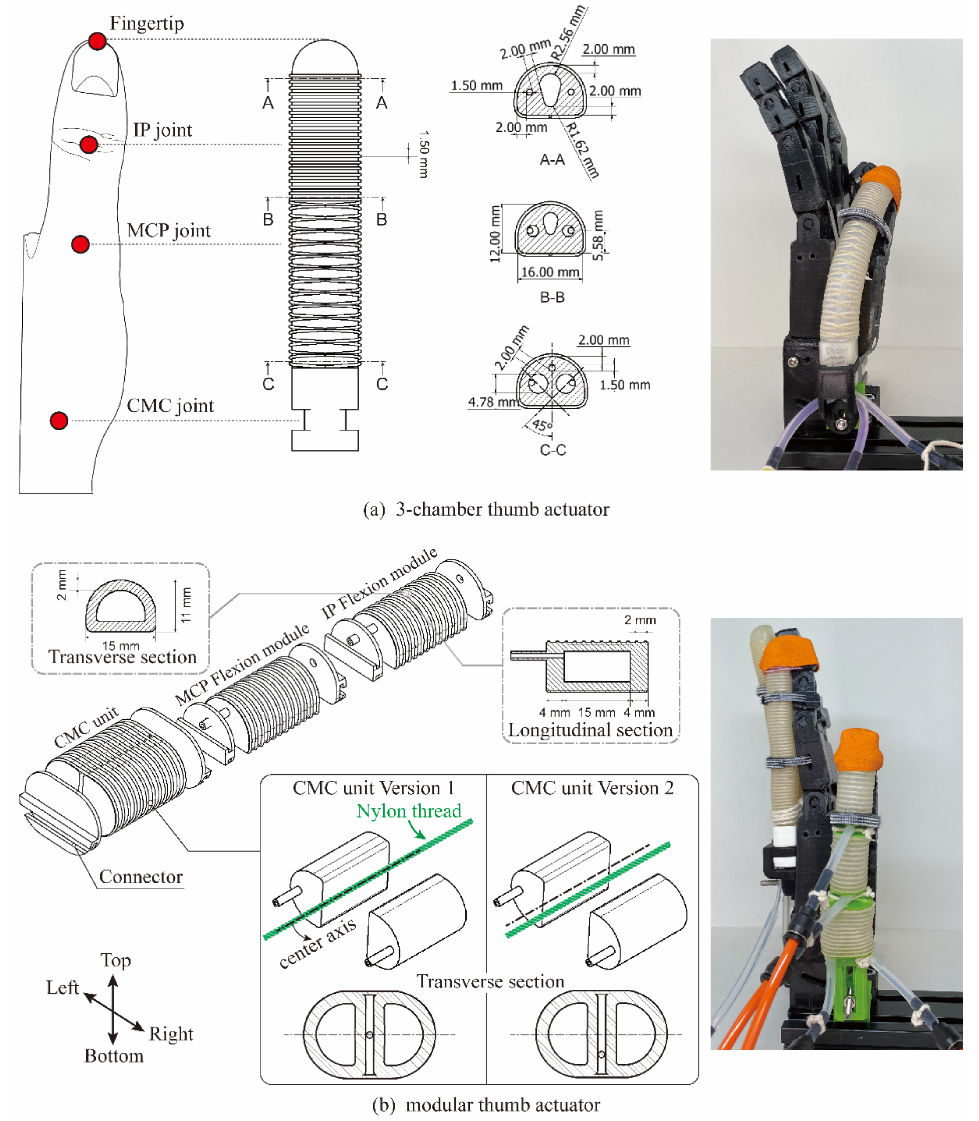
2.2.1. Whole-Finger Thumb Actuator: Three-Chamber Actuator

The 3C-ACT has the same geometrical structure and dimensions as the semicylindrical three-chamber actuator presented in [27] (Figure 1a). The middle chamber for thumb flexion was tapering up, with the maximum cross section area at the tip and the minimum at the root, matching the maximum flexion RoM requirement at the IP joint and the minimum at the CMC joint. The two side-chambers for abduction–adduction were in a contrary structure (tapering down) because thumb abduction only occurs at the CMC joint. Reinforcement fiber was coiled in two patterns: 21 loops of two-way hitching at the tip to facilitate deformation in flexion direction and 13 sets of double-helix at rest for permitting both abduction and flexion.

2.2.2. Modular Thumb Actuator

The actuator module was 23 mm long, which is long enough to fit into any of the thumb joints (Figure 1b). The fiber was wrapped in 12 loops of two-way hitching [28]. Two modules were connected head-to-tail, one for each of the IP joints and MCP joints, for impelling joint flexion. The bottom surface of the flexion module was made of stiffer silicon than the rest to limit the extension of the bottom surface, hence facilitating the module to flex.
The actuator unit for the CMC joint was designed based on the concept of utilizing pre-existing flexion modules to realize multi-DoF support without a noticeable sacrifice of ROM of abduction. According to the previous studies [16,18,23] that used a modular actuator for thumb abduction assistance, the modular unit cannot be simply placed transversely between the metacarpal bones of the thumb and the index finger because its initial length would diminish the thumb abduction RoM. Therefore, we designed a CMC unit attaching the bottom surfaces of two modules via an inextensible nylon thread (1.2 mm diameter) that ran longitudinally between them. The left module is responsible for CMC abduction, and the simultaneous air inflation of both modules induces CMC flexion. It is noteworthy that the two bottom surfaces cannot be completely attached because the two-module unit would have to overcome the elasticity of a shore 20A silicone (the stiffness of the silicone used in this study) block with a width of 4 mm (two times the chamber thickness) and a thickness of 15 mm (the width of the module), causing the unit to barely flex during simultaneous inflation of the two modules. Moreover, the CMC unit was wrapped with 12 loops of the single loop instead of two-way hitching because fibers in two-way hitching would restrict the elongation of the actuator surface that makes contact with the thumb, resulting in unwanted flexion during the air inflation of the left module (abduction). Accordingly, the optimization of the position of the inter-module thread would be important for effective multi-DoF support. We made two versions of the CMC actuator unit: one with the connective thread positioned at the center axis of the bottom surfaces (version 1), and the other with the thread located at a deeper position nearer to the thumb that equals the 3/4 of the module’s width (version 2).

2.3. Actuator Manufacture

Actuators were cast using PLA molds that were constructed with CAD software (Auto inventor) and printed with a 3D printer (Ultimaker 2 Extended+, Ultimaker B.V., Utrecht, The Netherlands). Smooth-Sil 940 (SmoothOn, Inc., Macungie, PA, USA) was used to make the bottom surface of the flexion module of the M-ACT. The rest of the M-ACT, as well as the entire actuator unit of 3C-ACT, was fabricated using DragonSkin 20. Ecoflex 00-30 was used for the final coating after fiber wrapping. The reinforcement fiber was 0.7-mm-diameter cotton thread. The connector between modules and the root connector for fixing the actuators were printed by the 3D printer.

3. Evaluations

For the purpose of practical evaluation, all the measurements were carried out with the designed actuator mounted on a dummy thumb/hand (Figure 2a) that mimicked the biomechanics of the participant’s hand. The air pressure of the 3C-ACT and the flexion module of the M-ACT were increased in 30 kPa increments, and the CMC unit of the M-ACT was increased in 15 kPa increments (corresponding to a smaller RoM requirement of the CMC joint than the other joints) until they reached their limit, at which point the actuator deformed extremely. Each measurement was repeated at least three times, and the mean value was evaluated.

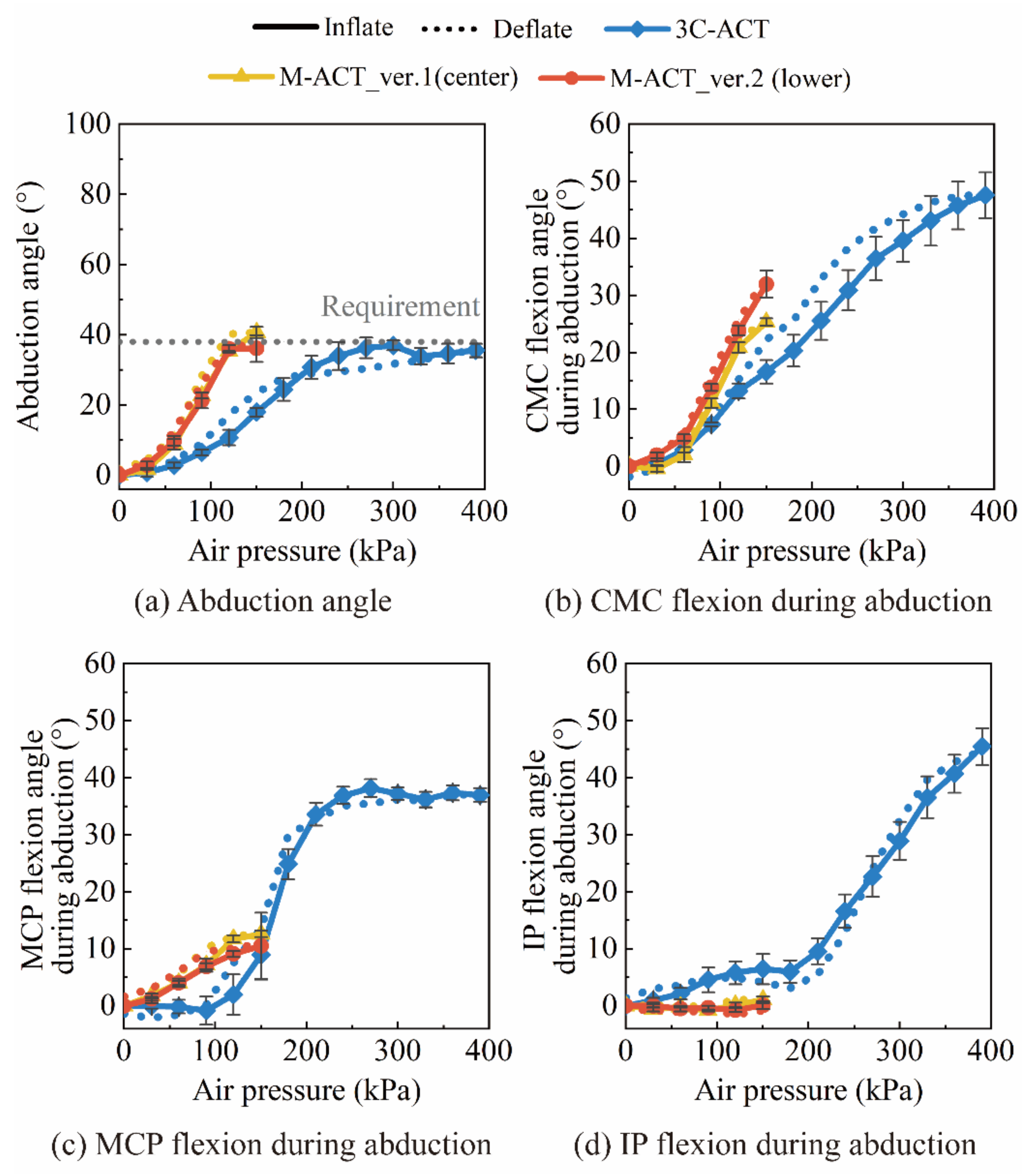
3.1. RoM Measurement

Fiver markers were attached to the dummy thumb at the root, fingertip, and three thumb joints, respectively (Figure 2a). A camera-based angle calculator constructed with OpenCV was used to calculate the joint angle. The three-dimensional coordinates of the markers were recorded with a depth camera (RealSenseTM Depth Camera D435, Intel®, Santa Clara, CA, USA), and the joint angle was determined using the angle enclosed by three markers. The flexion RoM was calculated from the x-axis and y-axis data, while the abduction RoM was calculated from the y-axis and z-axis data.

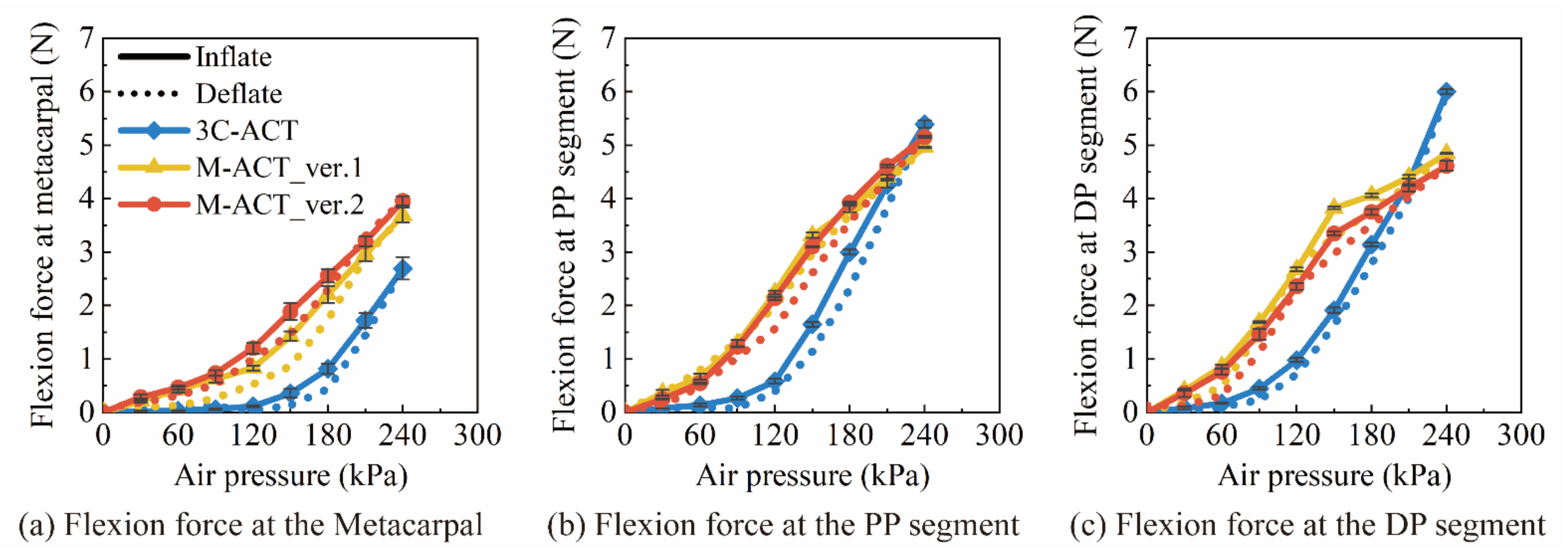
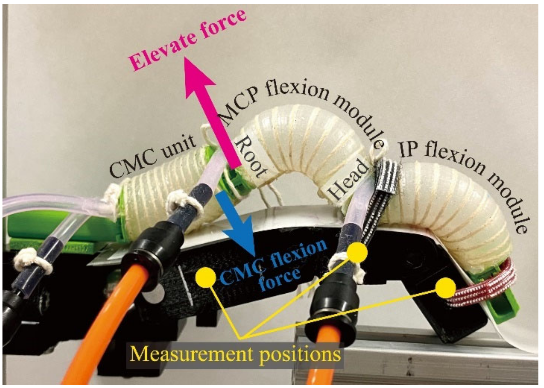
3.2. Force Output Measurement

Force generated at each thumb segment (distal phalanx (DP), proximal phalanx (PP), and metacarpal) was measured using a three-axis load cell (USL06-H5 Load cell, max: 100N, Tec Gihan, Kyoto, Japan) (Figure 2b).
The finger segment to be measured was wired to the load cell during the measurement, permitting the rest of the finger to move freely. The flexion force was calculated as the net force of F_Y (elongation force) and F_Z (flexion force).
The overall abduction force of the 3C-ACT was measured at the middle of the DP segment because the side chamber for abduction extends from the root to the fingertip. The abduction force of the M-ACT was measured at the middle of the PP segment. The abduction force was F_Z, and the flexion force during an abduction was the net force of F_X (flexion force) and F_Y (elongation force).

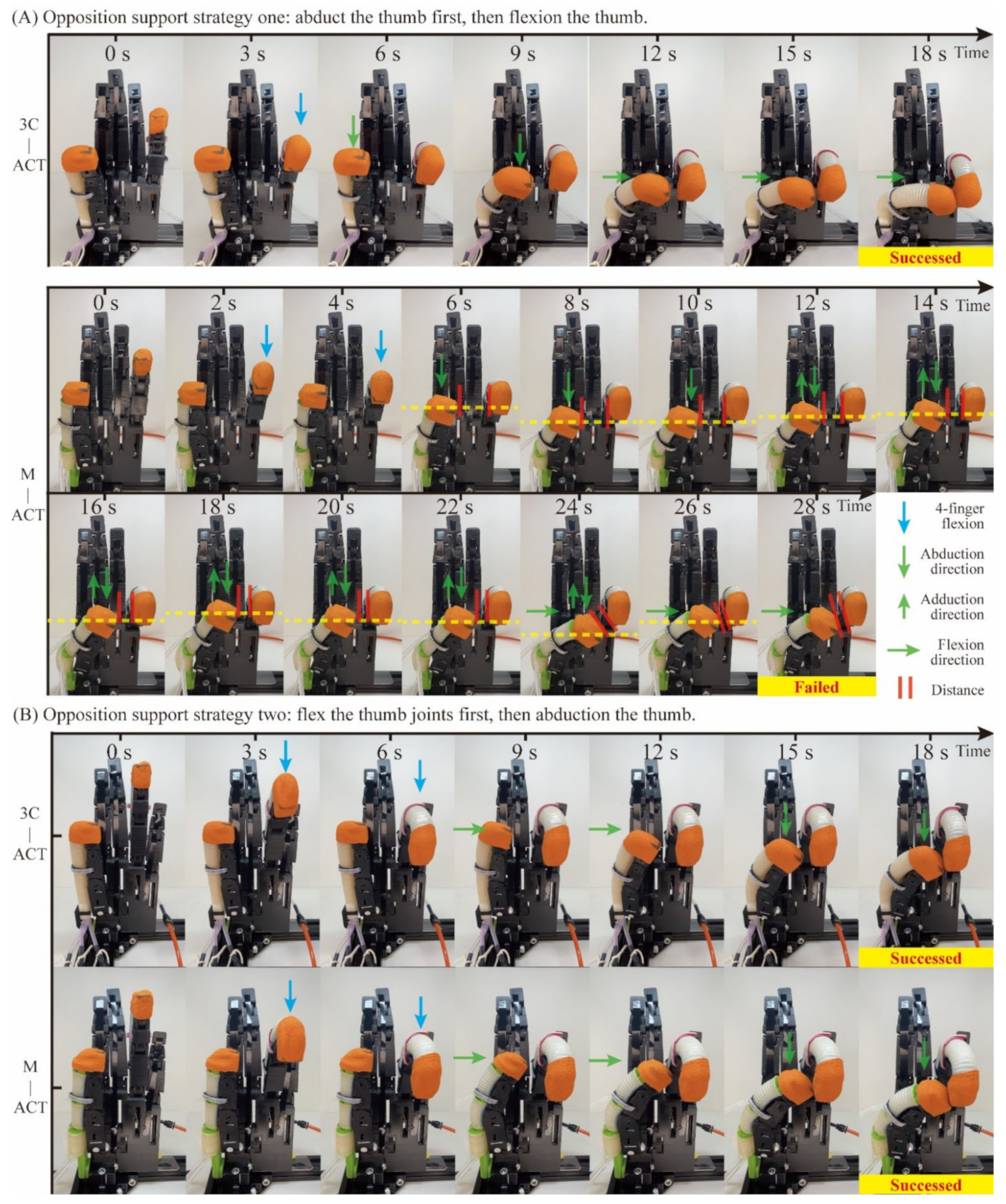
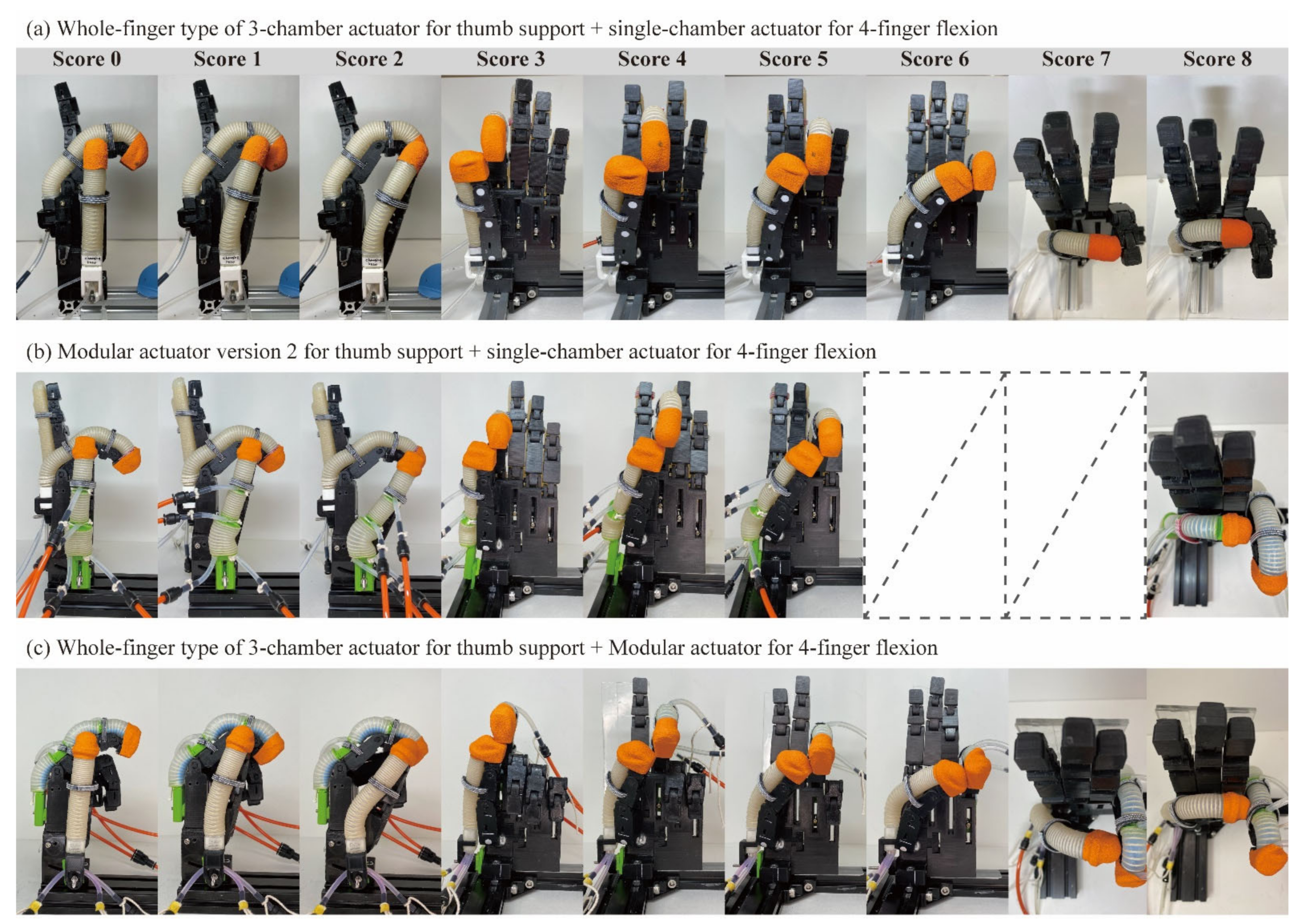
3.3. The Measurement of the Enhanced Kapndji Test

The Kapandji test has a score range of 0 to 10, indicating where a thumb could touch [29] (Figure 2c). The scores of 9 and 10 were omitted because these movements are rarely used in daily life.
The Kapandji test was performed with various combinations of actuators:
  • A 3C-ACT for thumb assistance and a conventional single-chamber actuator for four-finger assistance.
  • An M-ACT for thumb assistance and a single-chamber actuator for four-finger assistance.
  • A 3C-ACT for thumb assistance and an M-ACT with three flexion modules connected in series for four-finger assistance.
Moreover, the clinical Kapandji test only focuses on whether the thumb tip can contact the ten scoring points, though there are multiple thumb–finger postures for achieving the thumb–finger opposition. Figure 2d shows three different thumb–small finger postures for scoring point 6 shown in Figure 2c. Therefore, for the most critical thumb–small finger opposition, we measured three postures illustrated in Figure 2d, which require different degrees of thumb flexion and abduction.
The air pressure in the thumb actuator and the four-finger flexion actuator were carefully tuned to make the thumb reach the target positions specified by the Kapandji test. We inserted the three-axis load cell between fingers after confirming thumb-to-finger contact to record the change in pinch force with the pressurization of the thumb actuator and the four-finger flexion actuator (Figure 2e). The pinch force was evaluated as the net force of F_X, F_Y, and F_Z.
Thumb opposition failure was defined as the inability of the thumb to reach the target position after a sequence of air pressure adjustments.

4. Results

All the RoM and force output results were presented with mean ± SD.

4.1. RoM Results

4.1.1. Flexion RoM

The three thumb joints were flexed to their required angles when using the 3C-ACT and M-ACTs (Figure 3). The two M-ACTs bent the joints to the requirement at a lower air pressure compared with the 3C-ACT.
For the comparison between the two modular actuators, version 2, with a close-to-thumb bending axis, had a slightly larger flexion angle at each joint than version 1, with a bending axis in the center (CMC, MCP, and IP joints were flexed to 8.8°, 29.7°, and 84.1°, respectively when using version 1, and flexed to 17.5°, 32.3°, and 88.1° when using version 2).

4.1.2. Abduction RoM

All three thumb actuators rotated the metacarpal of the dummy thumb to the required angle (32°) in the palmar direction (Figure 4a). The thumb flexed during an abduction, particularly for the 3C-ACT (Figure 4b–d). It made all the thumb joints flex to a notably larger angle than M-ACTs.
Only the CMC actuator unit of the M-ACTs was inflated during the abduction. As a result, the CMC joint was flexed the most, followed by the MCP, while the IP joint was barely flexed at all. The M-ACT version 2 generally had a slightly larger flexion angle during abduction than version 1 (Figure 4b).

4.2. Force Output Results

4.2.1. Flexion Force

The M-ACTs had a larger maximal flexion force at the metacarpal bone than the 3C-ACT; however, they had a lesser maximal force at the DP segment than the 3C-ACT (Figure 5a,c).
The two versions of the M-ACT exerted similar intensities of maximum flexion force at all three thumb segments (version 1: 3.69 N of flexion force at the metacarpal, 4.96 N at PP, and 4.85 N at DP; version 2: 3.97 N at the metacarpal, 5.16 N at PP, and 4.62 N at DP) (Figure 5).
The 3C-ACT exhibited the greatest flexion force output at the DP, followed by the PP, and the lowest force output at the metacarpal, which is consistent with its design purpose.

4.2.2. Abduction Torque/Force

The M-ACT and 3C-ACT both had similar maximum torque for thumb abduction (Figure 6a). The abduction torque of the two versions of the M-ACT did not differ significantly, showing that the two versions had a similar abduction force. Combining the results of flexion force output, both versions had similar force output capability.
Similar to the abduction RoM results (Figure 4b–d), the 3C-ACT showed the highest flexion force during thumb abduction, followed by M-ACT version 2; M-ACT version 1 had the lowest (Figure 6b).

4.3. The Enhanced Kapandji Test Results

4.3.1. Kapandji Score

When using the same single-chamber actuator for four-finger flexion, the 3C-ACT was able to make the thumb’s fingertip touch the 0–8 positions in the Kapandji test (Figure 7a), whereas the M-ACT was unable to realize positions six and seven, which require the most thumb flexion and a relatively larger abduction to make contact with (Figure 7b). Figure A1A (lower) illustrates an example of thumb opposition failure. When using the 3C-ACT as the thumb actuator and the M-ACT as the four-finger flexion actuator, the thumb achieved a Kapandji score of 0–8 (Figure 7c).

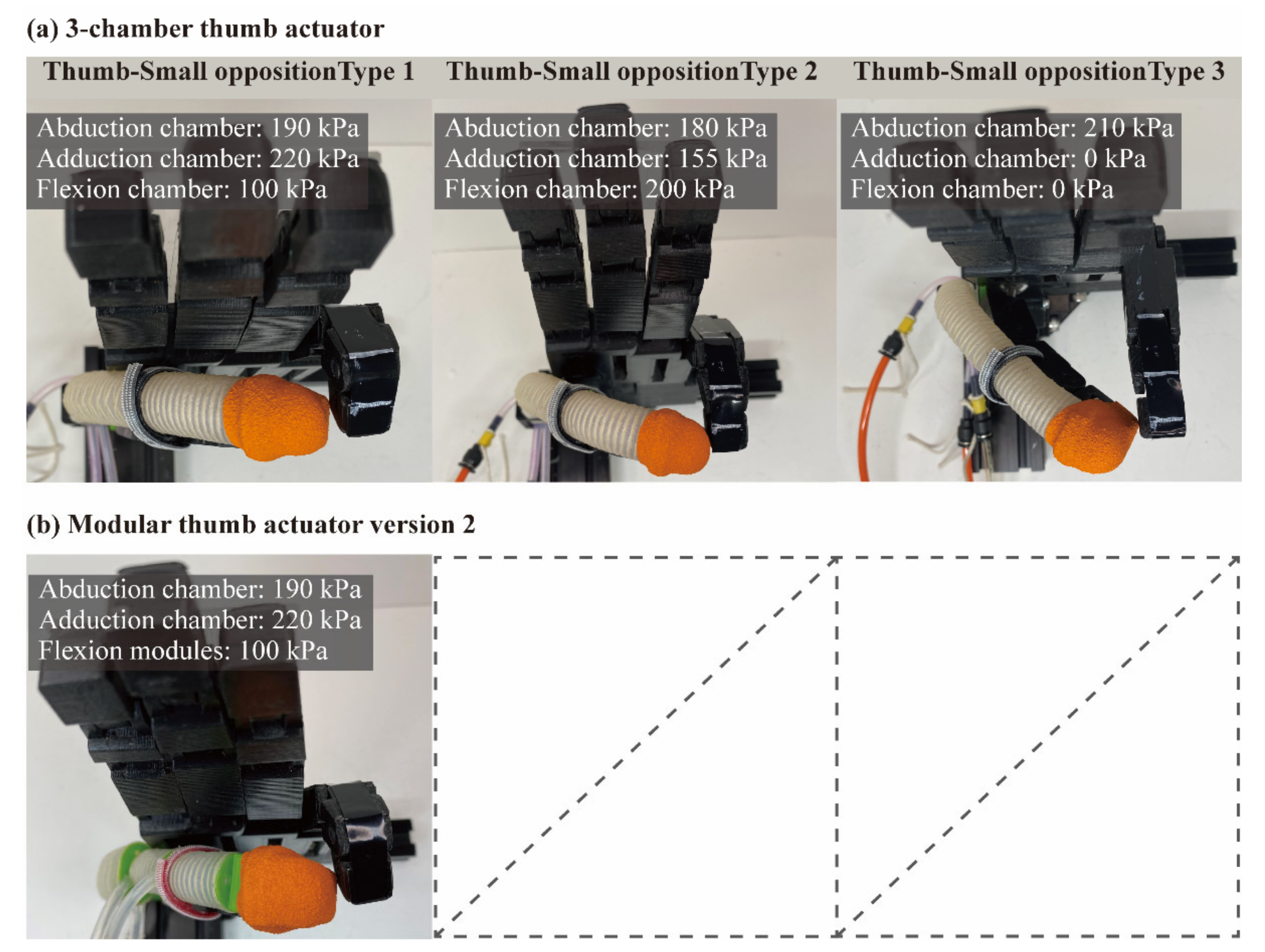
4.3.2. Thumb–Small Opposition

The 3C-ACT was successful in all three types of thumb–small opposition (Figure 8a). Both side chambers responsible for abduction and adduction were inflated to facilitate CMC joint flexion during type 1 and type 2 thumb–small oppositions.
However, the M-ACT was unable to accomplish types 2 and 3 of thumb–small opposition (Figure 8b) because both flexion and abduction were required for the CMC joint. It was challenging to adjust the air pressure of the two actuator modules in the CMC unit to get a stable actuator deformation for achieving multi-DoF thumb opposition. Only type 1 of the thumb–small opposition requires the flexion of all three joints; as a result, both of the modules in the CMC unit were inflated for the flexion of the CMC joint.

4.3.3. Thumb-Tip Pinch Force

The thumb and four fingers may form different arcs of closure at each thumb-tip opposition. In addition, the load cell placement (i.e., angle, contact position) varies from time to time, which affects the pinch force values. For a general assessment, the pinch force was calculated as the average of three times of measurements, and the value at the maximum air inflation was evaluated.
In general, the thumb generated greater pinch forces with the index and middle fingers than with the ring and little fingers, the fingers furthest away from the thumb (Table 2).
When the identical single-chamber actuator was used for four-finger flexion, the thumb actuators of the M-ACT and 3C-ACT generated similar levels of pinch force with the three fingers, except for the small finger. The combination of the 3C-ACT and M-ACT produced a greater pinch force than the other two actuator combinations, particularly for the thumb and two fingers next to it (index and middle fingers).

5. Discussion

In this section, we evaluated the two M-ACT versions and determined which one works better in terms of thumb flexion and abduction assistance. The M-ACT was then compared with the 3C-ACT in terms of flexion, abduction, and opposition assistance.

5.1. Comparison between the Two Versions of Modular Thumb Actuator

The two versions of the CMC unit of the M-ACT have a similar actuator structure, only differing in the position of the fiber axis (bending axis) for restricting the longitudinal elongation.
In line with the design purpose, version 2, with an off-center bending axis, showed a greater flexion RoM than version 1 (Figure 3). Nevertheless, it did not exhibit a significant advantage in flexion force output, even at the metacarpal bone (corresponding to the CMC joint, Figure 5). The force was measured by inflating all actuator modules simultaneously, including two flexion modules and the CMC unit. Therefore, the measured force was the two actuator modules’ combined force before and after the measurement position. In contrast to the flexion module for the IP joint, which had both ends fixed, the connection part of the CMC unit and MCP flexion module was nearly impossible to fix on the hand’s dorsal side (Figure 9). As a result, during large air inflation, the root of the MCP flexion module would elevate the head of the CMC unit, thus reducing the flexion effect of the CMC unit.
Additionally, the two versions of the M-ACT differed solely in the CMC unit, but the result showed that version 2 had a slightly greater flexion RoM in the CMC joint (the root section) and the IP joint (the tip section). Since the surface of a finger extends with finger flexion, mostly as the extension of the knuckle creases, the actuator modules need to move or elongate to maintain an efficient bending torque. Version 2 flexed more intensely than version 1 (Figure 3), indicating a greater elongation of the top surface of version 2. The lengthened top part may push the two flexion modules toward the fingertip to some extent. Consequently, the mutual effects between adjacent modules may affect the bending performance of the whole actuator.
In terms of thumb abduction support, both versions of the M-ACT could impel the thumb to abduct to a similar angle (Figure 4a) and give comparable magnitudes of abduction torque (Figure 6a). However, due to its off-center bending axis, version 2 had a larger RoM (Figure 4b–d) and force output (Figure 6b) in the flexion direction during the air inflation of the left module of the CMC unit (abduction).
In general, though version 2 had an undesirable flexion during thumb abduction, it outperformed version 1 in thumb flexion support and may be helpful for the flexion of other joints (i.e., IP joint). Accordingly, the M-ACT version 2 was selected for the following comparison with the 3C-ACT.

5.2. Comparison between the Modular Actuator and the Three-Chamber Actuator

5.2.1. Single-DoF Support Performance

Both the 3C-ACT and M-ACT were capable of bending the thumb joints to their limited angles (Figure 3 and Figure 4a). The 3C-ACT could generate a maximum flexion force of 6.0 N at the DP segment (Figure 5c), and the M-ACT could generate a maximum force of 5.2 N at the PP segment (Figure 5b). There has seldom been a study that assessed the force of intrinsic hand muscles required for passive finger flexion. As a reference, the extrinsic muscle group tendon force generated during passive finger motions could be up to 8.8 N [31]. The overall force output of the two actuators on the whole thumb would be intense enough to impel a passive thumb motion, thus demonstrating their capability in supporting thumb flexion motions.
As for the difference between the two thumb actuator types, the 3C-ACT had a lower flexion force at the metacarpal bone than the M-ACT (Figure 5a) because the middle chamber of the 3C-ACT has the smallest cross section area at the root part, resulting in a much smaller effective area (which directly affects the bending angle of an actuator), than the M-ACT. The maximum cross section of the 3C-ACT’s middle chamber (at the fingertip) was still smaller than that of the M-ACT (Figure 1), but it produced a larger force output at the DP segment than the M-ACT (Figure 5c). The flexion force was calculated as the combined force of elongation and flexion forces. Due to its double-helix fiber wrapping method, the 3C-ACT may have a greater elongation force than the M-ACT. Such actuator elongation would also be helpful for improving the flexion angle of all three joints.
Moreover, compared with the M-ACT, the 3C-ACT had a significantly larger undesired flexion RoM (Figure 4b–d) and force output (Figure 6b) during thumb abduction. Unlike the CMC unit of the M-ACT, which has more than two symmetry axes in structure (symmetric in both top–bottom and left–right, Figure 1b), the 3C-ACT is only symmetric in left–right (Figure 1a). During left chamber pressurization, the curved top surface of the 3C-ACT would expand more vigorously than the bottom surface, resulting in deformation in the flexion direction. Accordingly, the M-ACT’s CMC unit with two modules (or chambers) may be more structurally beneficial to independent flexion and abduction support than the actuator with three chambers.
In general, the two types of thumb actuators have equivalent thumb flexion assist capabilities. Structurally, both have the potential to provide sufficient support in thumb flexion and abduction with less sacrifice in RoM when compared with the soft finger actuators designed in previous studies [10,12,18,23]. However, the M-ACT would be more suitable for independent flexion and abduction assistance due to less undesired flexion during an abduction.

5.2.2. Multi-DoF Support Performance

When using the identical single-chamber actuator to assist the four-finger flexion, the 3C-ACT achieved all the Kapandji scores (0–8, Figure 7a); however, the M-ACT was unable to make the thumb come in contact with the small finger (a Kapandji score of 0–5 and 8, Figure 7b). The result of the Kapandji test is affected by two factors: first, during the measurement of the two actuators, the four-finger flexion actuator may flex the four-finger to different angles, and second, the M-ACT may be inferior in thumb opposition support. Table A1 shows that when using the M-ACT and 3C-ACT to perform thumb–finger opposition motions, the four-finger flexion actuator was inflated to similar air pressure ranges. Accordingly, the two actuators had to flex and abduct the thumb to similar angles during the Kapandji test. Therefore, the latter would be the reason for the lower Kapandji score of the M-ACT.
Unlike the air chambers in the 3C-ACT, which are in charge of the actuator bending in identical directions (the middle chamber for flexion, the left side-chamber for abduction, and the right side-chamber for adduction), each chamber of the M-ACT’s CMC unit is responsible for the bending in two directions (the left module is responsible for flexion and abduction, and the right module for flexion and adduction).
There would be two strategies for manually inflating the M-ACT for realizing thumb opposition movements. One strategy is to inflate the left module first to abduct the thumb fingertip to the same height as the four-fingertip, then inflate the right module to flex the CMC joint (Figure A1A). The pressurization of the right module did not flex the CMC joint on the basis of a certain degree of abduction; instead, it sacrificed the abduction for flexion. The air pressure in the two modules must be adjusted repeatedly until the thumb’s fingertip reaches the objective position, which is a difficult procedure to complete manually, as even a minor alteration at the CMC joint would deviate the fingertip (distal part) from the objective position. The other strategy is to first inflate the two modules for CMC flexion and then increase the air pressure in the left module for thumb abduction (Figure A1B). Either strategy is difficult to achieve a steady and fluent thumb–small opposition support, especially for postures that require both large thumb flexion and abduction because the deformation of the CMC unit in different DoF is not independent. The 3C-ACT, however, is simpler to manipulate. We could adopt either of the above-mentioned strategies to achieve thumb opposition with a less air tuning procedure because its deformation in different DoF is independent (additive), but not mutually depleting. Accordingly, the three-chamber structure of the 3C-ACT may be more beneficial to thumb opposition (multi-DoF) support.
For the same reason, the 3C-ACT can realize all three types of thumb–small positions (Figure 8a), whereas the M-ACT can only realize the first type of thumb–small opposition, which only requires thumb flexion (Figure 8b). Notably, both side chambers of the 3C-ACT were inflated to facilitate CMC joint flexion; otherwise, type 1 and type 2 thumb–small oppositions are impossible to achieve. Though the required angle for CMC joint flexion was 13° (Table 1), a rather minor value, it is critical for the thumb to make contact with the finger or position that is away from it.
Since the 3C-ACT outperformed the M-ACT in thumb opposition support and the M-ACT was proven to be proficient at single-DoF support in Section 5.2.1, we kept the 3C-ACT as the thumb actuator and utilized the M-ACT as the four-finger flexion actuator. This combination of 3C-ACT and M-ACT achieved all the Kapandji scores (Figure 7c) and a stronger pinch force than the other two combinations, especially for thumb–index pinch and thumb–middle pinch (Table 2). The greatest pinch force, 6.2 N, was generated between the thumb and index finger, demonstrating that the actuators can assist the hand in gripping an object weighing no more than 1.3 kg (12.4 N). Compared with a previous study [13] that measured 1.66 N of thumb–index pincer force using their designed actuator, our actuators could perform more powerful hand manipulation tasks.
Accordingly, utilizing the 3C-ACT as the thumb actuator and the M-ACT as the 4-finger actuator may be the best solution for the robotic glove.
Given the advantages of the two types of thumb actuators, they may be appropriate for distinct hand rehabilitation scenarios. For example, the M-ACT may be useful for patients with severe finger contracture because it can urge the thumb to perform independent abduction and flexion movements, allowing the targeted muscle groups and joints to be stretched and trained separately. The 3C-ACT may be beneficial for advanced exercises such as gross grip and finger pinch (tweezer grip) [32] to improve grip strength.

6. Contribution and Future Work

This is the first study to comprehensively evaluate and compare whole-finger and modular soft actuators in terms of practical thumb assist performance. The advantages and disadvantages of the two actuator types for the thumb were analyzed, and an effective actuator combination for a soft robotic glove was provided. Our findings highlighted:
  • The superior single-DoF support capability of the modular thumb actuator.
  • The superior multi-DoF support capability of the whole-finger thumb actuator.
Based on these findings, different thumb-assisting strategies could be taken with the latest soft actuating technology, depending on the degree of hand function impairment.
In this study, the thumb assist performance of the two actuators was examined using a dummy hand that imitated a participant’s hand. Similar trials on real hands or patients’ hands would be needed for a more practical evaluation. A long-term experiment is also required to assess the effect of the proposed actuator combination (three-chamber thumb actuator and modular four-finger flexion actuator) on the rehabilitation of hand functions. Most importantly, control methods for the three-chamber and modular actuators must be developed.

7. Conclusions

This study evaluated the design of the modular thumb actuator (M-ACT) and compared it with the whole-finger thumb actuator (3C-ACT) in terms of thumb flexion, abduction, opposition, and pinch strength.
The CMC unit of the modular thumb actuator was designed into two versions, one with a center axis (version 1) and another with an off-center axis (version 2). Version 2 impelled the thumb joints to flex to a greater angle and provided a larger flexion force than version 1 in addition to its comparable abduction performance to version 1.
In the comparison between the M-ACT version 2 and 3C-ACT, both types achieved the required flexion angle and provided sufficient flexion force; however, the M-ACT had less undesired flexion during thumb abduction, thus making it more suitable for independent flexion and abduction (single-DoF) support.
In respect to thumb opposition support, the 3C-ACT obtained a Kapandji score of 0–8, whereas the M-ACT obtained a score of 0–5. The deficit of the M-ACT in thumb opposition support would be due to its multi-DoF support mechanism. Unlike the 3C-ACT, which can modify its deformation in different DoF by adjusting distinct chambers, the M-ACT cannot adjust the deformation in different DoF independently; an increase in CMC flexion angle reduces the abduction angle and vice versa. Therefore, the 3C-ACT would be more manipulable and easier to realize thumb opposition support.
When the 3C-ACT was used for thumb assistance and the M-ACT was used for four-finger flexion support, the dummy hand performed all the opposition postures in the Kapandji test and achieved a higher pinch force than when the two actuators were used as thumb actuators and collaborated with a single-chamber actuator for four-finger flexion, indicating that the combination of the 3C-ACT and M-ACT may be an optimal solution for a robotic glove.

Author Contributions

Y.W. was the main author of the manuscript. She designed, prototyped, and tested the three-chamber actuator. S.K. designed and prototyped the modular type of flexion actuator. He was one of the main advisors of the manuscript revision. S.H. and Y.-H.H. assisted in data analysis and participated in the revision of the manuscript. W.Y. was the main supervisor and advisor of this work and contributed to the revision of the manuscript. All authors have read and agreed to the published version of the manuscript.

Funding

This research received no external funding.

Acknowledgments

The first author, Yuanyuan Wang, thanks the LOTTE Foundation for their financial support for her doctoral study. The authors would like to thank Zhongchao Zhou, Yuxi Lu, Pablo E. Tortós Vinocour, and Wen Dong for their support in the experiments.

Conflicts of Interest

The authors declare no conflict of interest.

Abbreviations

WPIwhole-person impairment
RoMrange of motion
DoFdegree of freedom
MCPmetacarpophalangeal (thumb middle joint)
CMCcarpometacarpal (thumb root joint)
IPinterphalangeal (thumb tip joint)
DPdistal phalanx (thumb tip segment)
PPproximal phalanx (thumb middle segment)
M-ACTmodular finger actuator
3C-ACTthree-chamber actuator

Appendix A

Table A1. The air pressure range of actuators during thumb to finger pinching (kPa).
Actuator
combination
Thumb–IndexThumb–MiddleThumb–RingThumb–Small
Chamber for Thumb AbductionChamber for Thumb FlexionChamber for
4-Finger Flexion
Chamber for Thumb AbductionChamber for Thumb FlexionChamber for
4-Finger Flexion
Chamber for Thumb AbductionChamber for Thumb FlexionChamber for
4-Finger Flexion
Chamber for Thumb AbductionChamber for Thumb FlexionChamber for
4-Finger Flexion
3C-ACT
+
single-chamber ACT
1500–24090–1501800–240160–2401950–240160–2402100–240150–240
M-ACT
+
single-chamber ACT
1000–24090–1501000–240160–2409090–240130–240---
3C-ACT
+
M-ACT
900–240230–3001500–240280–300170120–240300 (max)190150–240260–300
Figure A1. Two strategies for thumb opposition.
Applsci 12 03735 g0a1
Strategy one (Figure A1A): abduct the thumb first, then flex the thumb joints. The 3C-ACT achieved thumb–small opposition in 18 s, whereas the M-ACT had to repeatedly adjust the air inflation in the two modules of the CMC unit (from 12 to 28 s) and did not achieve thumb–small opposition after a sequence of air pressure adjustments. Strategy two (Figure A1B): flex the thumb joints first, then abduct the thumb. Both the 3C-ACT and M-ACT realized thumb–ring opposition within 18 s. 3C-ACT: three-chamber actuator; M-ACT: modular type of thumb actuator.

References

  1. Raghavan, P. The nature of hand motor impairment after stroke and its treatment. Curr. Treat. Options Cardiovasc. Med. 2007, 9, 221–228. [Google Scholar] [CrossRef]
  2. Australia Government. Commission for the Safety Rehabilitation and Compensation of Commonwealth Employee; Guide to the Assessment of the Degree of Permanent Impairment (Edition 2.1). 2009. Available online: https://www.comcare.gov.au/__data/assets/pdf_file/0015/100905/Guide_to_the_assessment_of_the_degree_of_permanent_impairment_the_Guide_Edition_2.1_of_the_Guide_PDF,_1.84_MB.pdf (accessed on 25 February 2022).
  3. Fischer, H.C.; Triandafilou, K.M.; Thielbar, K.O.; Ochoa, J.M.; Lazzaro, E.D.; Pacholski, K.A.; Kamper, D.G. Use of a Portable Assistive Glove to Facilitate Rehabilitation in Stroke Survivors With Severe Hand Impairment. IEEE Trans. Neural Syst. Rehabil. Eng. 2016, 24, 344–351. [Google Scholar] [CrossRef] [PubMed]
  4. Proulx, C.E.; Beaulac, M.; David, M.; Deguire, C.; Haché, C.; Klug, F.; Kupnik, M.; Higgins, J.; Gagnon, D.H. Review of the effects of soft robotic gloves for activity-based rehabilitation in individuals with reduced hand function and manual dexterity following a neurological event. J. Rehabil. Assist. Technol. Eng. 2020, 7, 2055668320918130. [Google Scholar] [CrossRef] [PubMed]
  5. Radder, B.; Prange-Lasonder, G.B.; Kottink, A.I.R.; Melendez-Calderon, A.; Buurke, J.H.; Rietman, J.S. Feasibility of a wearable soft-robotic glove to support impaired hand function in stroke patients. J. Rehabil. Med. 2018, 50, 598–606. [Google Scholar] [CrossRef] [PubMed] [Green Version]
  6. Xiloyannis, M.; Cappello, L.; Khanh, D.B.; Yen, S.C.; Masia, L. Modelling and Design of a Synergy-Based Actuator for a Tendon-Driven Soft Robotic Glove. In Proceedings of the 2016 6th IEEE International Conference on Biomedical Robotics and Biomechatronics (BioRob), Singapore, 26–29 July 2016; pp. 1213–1219. [Google Scholar] [CrossRef]
  7. Chirinos, S.C.; Vela, E.A. A Modular Soft Robotic Exoskeleton for Active Hand Rehabilitation after Stroke. In Proceedings of the 2021 IEEE Engineering International Research Conference (EIRCON), Lima, Peru, 27–29 October 2021; pp. 1–4. [Google Scholar] [CrossRef]
  8. Yoon, J.G.; Lee, M.C. Design of tendon mechanism for soft wearable robotic hand and its fuzzy control using electromyogram sensor. Intell. Serv. Robot. 2021, 14, 119–128. [Google Scholar] [CrossRef]
  9. Jo, I.; Bae, J. Design and control of a wearable and force-controllable hand exoskeleton system. Mechatronics 2017, 41, 90–101. [Google Scholar] [CrossRef]
  10. Connolly, F.; Walsh, C.J.; Bertoldi, K. Automatic design of fiber-reinforced soft actuators for trajectory matching. Proc. Natl. Acad. Sci. USA 2017, 114, 51–56. [Google Scholar] [CrossRef] [PubMed] [Green Version]
  11. Polygerinos, P.; Galloway, K.C.; Savage, E.; Herman, M.; Donnell, K.O.; Walsh, C.J. Soft Robotic Glove for Hand Rehabilitation and task Specific Training. In Proceedings of the IEEE International Conference on Robotics and Automation, Seattle, WA, USA, 25–30 May 2015; pp. 2913–2919. [Google Scholar] [CrossRef]
  12. Polygerinos, P.; Wang, Z.; Galloway, K.C.; Wood, R.J.; Walsh, C.J. Soft robotic glove for combined assistance and at-home rehabilitation. Robot. Auton. Syst. 2015, 73, 135–143. [Google Scholar] [CrossRef] [Green Version]
  13. Yap, H.K.; Ang, B.W.K.; Lim, J.H.; Goh, J.C.H.; Yeow, C.-H. A Fabric-Regulated Soft Robotic Glove with User Intent Detection Using EMG and RFID for Hand Assistive Application. In Proceedings of the 2016 IEEE International Conference on Robotics and Automation (ICRA), Stockholm, Sweden, 16–21 May 2016; pp. 3537–3542. [Google Scholar] [CrossRef]
  14. Polygerinos, P.; Lyne, S.; Wang, Z.; Nicolini, L.F.; Mosadegh, B.; Whitesides, G.M.; Walsh, C.J. Towards a Soft Pneumatic Glove for Hand Rehabilitation. In Proceedings of the IEEE/RSJ International Conference on Intelligent Robots and Systems, Tokyo, Japan, 3–7 November 2013; pp. 1512–1517. [Google Scholar] [CrossRef]
  15. Gu, G.; Wang, D.; Ge, L.; Zhu, X. Analytical Modeling and Design of Generalized Pneu-Net Soft Actuators with Three-Dimensional Deformations. Soft Robot. 2021, 8, 462–477. [Google Scholar] [CrossRef]
  16. Wang, J.; Fei, Y.; Pang, W. Design, Modeling, and Testing of a Soft Pneumatic Glove With Segmented PneuNets Bending Actuators. IEEE/ASME Trans. Mechatron. 2019, 24, 990–1001. [Google Scholar] [CrossRef]
  17. Yap, H.K.; Lim, J.H.; Nasrallah, F.; Goh, J.C.H.; Yeow, R.C.H. A Soft Exoskeleton for Hand Assistive and Rehabilitation Application Using Pneumatic Actuators with Variable Stiffness. In Proceedings of the 2015 IEEE International Conference on Robotics and Automation (ICRA), Seattle, WA, USA, 26–30 May 2015; pp. 4967–4972. [Google Scholar] [CrossRef]
  18. Li, M.; Wang, T.; Zhuo, Y.; He, B.; Tao, T.; Xie, J.; Xu, G. A Soft Robotic Glove for Hand Rehabilitation Training Controlled by Movements of the Healthy Hand. In Proceedings of the 7th International Conference on Ubiquitous Robots (UR), Kyoto, Japan, 22–26 June 2020; pp. 62–67. [Google Scholar] [CrossRef]
  19. Shiota, K.; Kokubu, S.; Tarvainen, T.V.; Sekine, M.; Kita, K.; Huang, S.Y.; Yu, W. Enhanced Kapandji test evaluation of a soft robotic thumb rehabilitation device by developing a fiber-reinforced elastomer-actuator based 5-digit assist system. Robot. Auton. Syst. 2018, 111, 20–30. [Google Scholar] [CrossRef]
  20. Heung, K.H.L.; Tong, R.K.Y.; Lau, A.T.H.; Li, Z. Robotic Glove with Soft-Elastic Composite Actuators for Assisting Activities of Daily Living. Soft Robot. 2019, 6, 289–304. [Google Scholar] [CrossRef]
  21. Heung, H.L.; Tang, Z.Q.; Shi, X.Q.; Tong, K.Y.; Li, Z. Soft Rehabilitation Actuator With Integrated Post-stroke Finger Spasticity Evaluation. Front. Bioeng. Biotechnol. 2020, 8, 111. [Google Scholar] [CrossRef] [Green Version]
  22. Guo, N.; Sun, Z.; Wang, X.; Yeung, E.H.K.; To, M.K.T.; Li, X.; Hu, Y. Simulation analysis for optimal design of pneumatic bellow actuators for soft-robotic glove. Biocybern. Biomed. Eng. 2020, 40, 1359–1368. [Google Scholar] [CrossRef]
  23. Hu, D.; Zhang, J.; Yang, Y.; Li, Q.; Li, D.; Hong, J. A Novel Soft Robotic Glove with Positive-Negative Pneumatic Actuator for Hand Rehabilitation. In Proceedings of the IEEE/ASME International Conference on Advanced Intelligent Mechatronics, Virtual event, 6–10 July 2020; pp. 1840–1847. [Google Scholar] [CrossRef]
  24. Jones, L.A.; Lederman, S.J. Human Hand Function; Oxford University Press: New York, NY, USA, 2007; pp. 141–143. [Google Scholar] [CrossRef]
  25. Barakat, M.J.; Field, J.; Taylor, J. The Range of Movement of the Thumb. Hand 2013, 8, 179–182. [Google Scholar] [CrossRef] [Green Version]
  26. Holzbauer, M.; Hopfner, M.; Haslhofer, D.; Kwasny, O.; Duscher, D.; Froschauer, S.M. Radial and palmar active range of motion measurement: Reliability of six methods in healthy adults. J. Plast. Surg. Hand Surg. 2020, 55, 41–47. [Google Scholar] [CrossRef]
  27. Wang, Y.; Kokubu, S.; Zhou, Z.; Guo, X.; Hsueh, Y.-H.; Yu, W. Designing Soft Pneumatic Actuators for Thumb Movements. IEEE Robot. Autom. Lett. 2021, 6, 8450–8457. [Google Scholar] [CrossRef]
  28. Kokubu, S.; Wang, Y.; Tortós Vinocour, P.E.; Lu, Y.; Huang, S.; Nishimura, R.; Hsueh, Y.-H.; Yu, W. Evaluation of Fiber-Reinforced Modular Soft Actuators for Individualized Soft Rehabilitation Gloves. Actuators 2022, 11, 84. [Google Scholar] [CrossRef]
  29. Kapandji, A.I. Clinical evaluation of the thumb’s opposition. J. Hand Ther. 1992, 5, 102–106. [Google Scholar] [CrossRef]
  30. De Kraker, M.; Selles, R.W.; Schreuders, T.A.R.; Stam, H.J.; Hovius, S.E.R. Palmar Abduction: Reliability of 6 Measurement Methods in Healthy Adults. J. Hand Surg. 2009, 34, 523–530. [Google Scholar] [CrossRef]
  31. Schuind, F.; Garcia-Elias, M.; Cooney, W.P.; An, K.-N. Flexor tendon forces: In vivo measurements. J. Hand Surg. 1992, 17, 291–298. [Google Scholar] [CrossRef]
  32. Ellegaard, K.; von Bülow, C.; Ropke, A.; Bartholdy, C.; Hansen, I.S.; Rifbjerg-Madsen, S.; Henriksen, M.; Wæhrens, E.E. Hand exercise for women with rheumatoid arthritis and decreased hand function: An exploratory randomized controlled trial. Arthritis Res. Ther. 2019, 21, 158. [Google Scholar] [CrossRef] [PubMed] [Green Version]
Figure 1. Actuator structures.
Applsci 12 03735 g001
Figure 2. Measurement setups.
Applsci 12 03735 g002
Figure 3. Flexion RoM. CMC: carpometacarpal; MCP: metacarpophalangeal; IP: interphalangeal.
Applsci 12 03735 g003
Figure 4. The thumb abduction and flexion RoM during left-side chamber/module air inflation. CMC: carpometacarpal; MCP: metacarpophalangeal; IP: interphalangeal.
Applsci 12 03735 g004
Figure 5. Flexion force output. PP: proximal phalanx; DP: distal phalanx.
Applsci 12 03735 g005
Figure 6. Abduction torque and flexion force output during left-side chamber/module air inflation.
Applsci 12 03735 g006
Figure 7. Kapandji test results of three actuator combinations.
Applsci 12 03735 g007
Figure 8. Three types of thumb–small opposition.
Applsci 12 03735 g008
Figure 9. The deformation of a modular thumb actuator during excessive air inflation.
Applsci 12 03735 g009
Table 1. RoM requirements of the thumb and actuators.
Thumb MotionReal Thumb RoM [°]Actuator RoM
Requirement [°]
Goniometer ValueOpenCV Value
IP joint flexion908989
MCP joint flexion373232
CMC joint flexion151313
CMC joint abduction433838
RoM: range of motion; IP: interphalangeal; MCP: metacarpophalangeal; CMC: carpometacarpal.
Table 2. The pinch force of the 3-chamber actuator and modular actuator (N).
Actuator CombinationThumb–IndexThumb–MiddleThumb–RingThumb–Small
3C-ACT (thumb) + single-chamber ACT (4-finger)5.74.13.74
M-ACT (thumb) + single-chamber ACT (4-finger)5.84.33.2-
3C-ACT (thumb) + M-ACT (4-finger)6.25.03.53.3
3C-ACT: 3-chamber actuator; M-ACT: modular type actuator.
Publisher’s Note: MDPI stays neutral with regard to jurisdictional claims in published maps and institutional affiliations.

