Article

Robotic Magnetorheological Finishing Technology Based on Constant Polishing Force Control

1
School of Mechanical Engineering, Sichuan University, Chengdu 610065, China
2
Institute of Machinery Manufacturing Technology, China Academy of Engineering Physics, Mianyang 621054, China
*
Authors to whom correspondence should be addressed.
Appl. Sci. 2022, 12(8), 3737; https://doi.org/10.3390/app12083737
Submission received: 9 March 2022 / Revised: 29 March 2022 / Accepted: 5 April 2022 / Published: 7 April 2022
(This article belongs to the Special Issue Advanced Manufacturing Technologies and Their Applications, Volume II)

Abstract

:
The normal positioning error hinders the use of magnetorheological finishing (MRF) in robotic polishing. In this paper, the influence of robotic normal positioning error on the MRF removal rate is revealed, and a force-controlled end-effector for the robotic MRF process is presented. The developed end-effector is integrated into a six-axis industrial robot, and the robot positions the end-effector while the end-effector realizes the constant force control. A fused silicon mirror is polished, and the result shows that the proposed device effectively compensates for robotic normal positioning error and simultaneously maintains the stability of the polishing process. After deterministic polishing, the PV (peak to valley) of the figure is reduced from 126.56 nm to 56.95 nm , and the RMS (root mean square) is reduced from 22.15   nm to 7.59   nm .

1. Introduction

Magnetorheological finishing (MRF) is a deterministic sub-aperture polishing process that causes no sub-surface damage [1]. The deterministic removal of material is realized primarily by the dwell time method in numerical control polishing [2,3,4], meaning that the amount of material removal is controlled by the residence time of the polishing tool. The longer the polishing tool is in contact with the workpiece on a specific surface, the more material is removed from that area. Hence the magnetorheological removal function (i.e., the distribution function of the removal amount of the processed material in unit time) and its stability are critical in the polishing process.
Recently MRF technology has a relatively mature application and development on computer-numerical-control (CNC) machines, and magnetorheological technology and equipment have been engineered and commercialized [5]. Nonetheless, conventional MRF machine tools have drawbacks such as excessive weight and volume, restricted processing range, and high cost. Since the birth of industrial robots in the 1960s, the robot has been widely and effectively applied with the advantages of high flexibility and low cost in various fields, including welding, assembly, medical treatment, and life services. In the field of polishing, different from high-precision CNC machines, the robot is a rigid-flexible coupling body composed of multi-joints and multi-links. Thereby, the robot has poor rigidity and it is difficult to meet the requirements of positioning precision during the polishing process. To realize the application of robots in precision occasions, researchers have proposed a variety of solutions, classified into two categories of compensation: direct compensation of robotic errors and indirect compensation using work actuators. The direct correction of robotic error is also categorized into model-based error compensation and sensor-based error compensation [6]. Belchior et al. [7] used the finite element model to simulate and predict the robotic workload, combined with the robot stiffness model to realize the compensation of the robotic milling trajectory error and keep the overall trajectory error within 0.3 mm. Klimchik et al. [8] combine offline and online compensation by incorporating the theoretical milling force into the robotic stiffness model. This method pre-corrects the robotic work trajectory in the control program and re-corrects the work trajectory in the actual operation based on milling force feedback from the sensor, improving the precision of the robotic processing trajectory. Shi et al. [9] measured the robot end tool position based on the laser tracker, developing a closed-loop feedback system for robotic error compensation. The absolute positioning accuracy was increased to 0.087 mm , and the attitude accuracy of the robotic end reached 0.01 ° . Nevertheless, since commercial industrial robots have closed architecture systems, it is difficult to modify the closed control system of those robots using direct correction. To meet the demands of robot polishing, the method of indirect compensation using work actuators mainly includes active compliance and passive compliance. Generally speaking, an active compliance actuator has higher accuracy and better adaptability, achieving the positive effects of grinding technology [10,11]. Christian Brecher et al. [12] developed a pneumatic actuator for robotic gadget polishing and realized the force control adjustment of the robot surface polishing process with 0.5N resolution, greatly improving the robot polishing quality.
In terms of the combination of magnetorheological finishing technology and robot technology, Zhang et al. [13] integrated the exiting magnetorheological finishing tool on a six-axis industrial robot. A 1000 mm × 470 mm off-axis aspherical mirror was processed and achieved positive results. Nonetheless, the compensation of robotic normal positioning error is not disclosed. The immersion depth of the polishing ribbon is typically less than 0.5 mm, and the positioning error of the robot is typically greater than 0.2 mm without compensation [14,15,16]. Therefore, the robotic deterministic polishing process with a low MRF flow rate (less than 1000 mL/min) and low ribbon height (less than 2 mm) requires high normal positioning precision. To achieve a high convergence efficiency for robot magnetorheological polishing, it is indispensable to explore the influence of robot positioning error on the removal function and develop an appropriate trajectory compensation strategy.
To cope with the problems mentioned above, based on the current MRF unit design, a lightweight and intelligent design is conducted to match the load and precision requirements of robotic magnetorheological finishing. The magnetorheological finishing actuator for robots is developed using constant-force control to create a consistent and regulated material removal rate throughout the polishing operation. Different from a standard magnetorheological finishing unit, the actuator is capable of sensing and altering the polishing condition. Moreover, due to high flexibility and superior adaptability, the intelligent robot is able to take the place of the current commonly used high-precision machine tool. This furthers the promotion and application of robotic magnetorheological polishing technology with a low manufacturing cost and extends the robotic magnetorheological finishing to large-size and high-gradient freeform components.
The remainder of the paper is arranged as follows: Section 2 presents the magnetorheological removal function model and clarifies the influence of robotic normal positioning error on the stability of the removal function. Section 3 presents a robotic magnetorheological polishing system using an active force control technique. Section 4 verifies the effect of robotic MRF polishing based on constant force control by experiments. Finally, the conclusions are presented in Section 5.

2. Error of Removal Function

Equation (1) gives a classical version of Preston’s [17] ideas for the material removal rate.
R = K P V = K F n A c V ,  
where K is Preston’s coefficient determined by the physical and chemical properties of the polishing fluid (e.g., PH value, slurry, abrasive type, friction force) and the material of the machined workpiece, P is the normal pressure applied (i.e., normal force F n , the contact area A c between the polishing tool and the substrate being polished), and V is the relative velocity between the workpiece surface and the magnetorheological fluid.
Shorey [18] found that the material removal of MRF finishing is a process dominated by sheer force and supplemented by normal force. To address MRF, Shorey proposed a modified Preston’s model, as is shown in Equation (2):
R s = C p , M R F F n μ F n A s V ,  
where C p , M R F F n is the modified Preston’s coefficient, instead of A c in Equation (1), A s is the projected spot area where polishing occurs, and the coefficient of friction is μ correlating with the sheer force. The experiment indicates that μ lies between 0.4 and 0.6, within the typical range for the coefficient of friction reported for most materials in the sliding friction model [19,20].
Equation (2) reveals that the normal force F n between the MRF tool and the workpiece is one of the key factors affecting the removal function. The normal force F n of polishing can be affected by changing immersion depths (the depth at which the ribbon is immersed into the workpiece surface). The change of immersion depth results in the change of ribbon hardness and abrasive adhesion degree at the contact layer of the ribbon. Hence, the immersion depth is an important factor affecting the polishing force [21,22,23].
Under the existing experimental conditions, the sensitivity of the removal function to the normal positioning error is investigated by taking spots under different immersion depths on a high-precision MRF machine with a positioning precision of 3 μ m on the Z-axis, as illustrated in Figure 1.
Eight groups with different immersion depths from 0.2 mm to 0.55 mm are taken, with two spots in each group. A standard MR fluid is used in this experiment, consisting of Nano-diamond abrasives, iron powder, deionized water, and stabilizers. The Magnetorheological flow rate is 1800 mL/min, the wheel speed is 200 rpm with the diameter of the polishing wheel at 300 mm, the magnetorheological fluid moisture is 14.5%, and the ribbon height is adjusted to 1.3 mm.
The volumetric removal rate (VRR) is obtained from MRF spots. As illustrated in Figure 2, the result indicates a positive linear dependence on immersion depth under the conditions used in this experiment. The normal error of 0.05 mm results in a 0.000935   mm 3 / s error in volumetric removal rate. Since the immersion depth of 0.3–0.4 mm commonly is used in polishing, the relative error of the volumetric removal rate reaches 19–30% for the normal error 0.05 mm.
Overall, these results indicate that the stability of the MRF process is sensitive to normal positioning error. In the stable polishing process, the normal distance between the polishing tool and the workpiece surface should keep constant, guaranteeing the stability of the normal polishing force F n and the projected spot area A s . That ensures the sheer force affecting the material removal efficiency is stable. The normal positioning error between the polishing tool and the workpiece leads to uneven polishing force. The error of the material removal rate at each position of the workpiece surface leads to the poor quality of the final surface. To achieve the stability of the robotic magnetorheological finishing removal efficiency control, a method based on constant force control is proposed. The principle of a constant force end-effector and control system is designed.

3. Force-Controlled End-Effector

3.1. Mechanical Design

The innovative design of magnetorheological polishing equipment is carried out to fulfill the demands of robotic magnetorheological finishing, as illustrated in Figure 3.
The main components of the end-effector have compensatory parts, as illustrated in Figure 3a,b; compensation parts consisting of a servo motor and a linear ball screw mechanism, as shown in Figure 3c,d; control parts with a microcontroller, and polishing parts is an MRF circulation system, the detail is shown in Figure 3e: including a polishing wheel, a cycle system consist of two pumps, a nozzle, a recycling device, and a ribbon of magnetorheological; posture sensor and force sensor comprise the operating state detecting parts. The MRF circulation system recycles the magnetorheological fluid while also removing the surface materials of the polished workpiece. Both polishing tool attitude and normal force are obtained using the state sensor parts and sent to the microcontroller. The microcontroller processes the polishing force and converts it into the relevant position correction. It controls the compensation parts to complete the compensation action to maintain the stability of normal polishing force F n in the polishing process (i.e., the stability of MRF removal function). The advantage of the developed device is that it has an independent closed-loop control system, whose control effect only depends on its own and does not require any change of the robotic control system. Hence, the end-effector has good universality and practicability. The control principle of the magnetorheological polishing method based on constant force is illustrated in Figure 4.
The developed end-effector is to be integrated into a six-axis industrial robot. The industrial robot is used to position the end-effector and maintain that the polishing part of the MRF ribbon always contacts the workpiece surface vertically. The workpiece surface is subjected to force F and tangential friction force f at the polishing position N x , y , z . Since the end-effector is in vertical contact with the workpiece polishing part, the force F is the normal polishing force F n acting on the surface. According to Newton’s second law, the force of the end-effector is shown in Equation (3).
F s e n s o r = F g f 0 F n ,
where F g is the normal component of gravity and f 0 is the static friction force of structural, which is small enough that can be ignored. When the robotic positioning deviation occurs, the normal force F n changes. The mechanical changes after force signals to the microcontroller, using the force control model position correction, the force signal is converted to control motor speed and working time interval, driving the polishing parts to move in a normal direction through the linear ball screw mechanism. By changing the contact relationship between the magnetorheological ribbon and the polishing part until the normal force F n is controlled within the preset tolerance range, the relative position of the polishing process can be indirectly monitored and compensated to guarantee the stability of the polishing force.

3.2. Control System Modeling

The force-controlled end-effector directly interacts with the polishing environment. According to the principle of impedance control [24], the transfer function between the end-effector’s position correction Δ x = H H 0 and the polishing output force Δ F = F 0 F f is established as follows:
M H ¨ H 0 ¨ + B H ˙ H 0 ˙ + C H H 0 = F 0 F f .
After Laplace transforms, Equation (4) is written as
Δ x = Δ F Ms 2 + Bs + C   ,
where M ,   B , and C respectively represent the inertia parameter, damping parameter, and stiffness parameter of impedance control. The system structure of force-controlled end-effector is established as shown in Figure 5, including a position control inner loop and an impedance control outer loop, where H 0 represents the desired position of the polishing part; H is the compensated position of the polishing part; x e is the robot positioning error; Δ x is the position correction of the polishing part; Δ F is the difference between the desired contact force F 0 and the measured contact force F f ; K e is the environmental stiffness and the F f = K e H x e .

3.3. Controller Design

In the process of MRF, the components of MRF fluid change dynamically, mainly temperature and moisture. Generally, under the compensation function of the circulation system during the process, the fluctuation range of moisture is 0.5% and the fluctuation range of temperature is within 1 ℃. Hence, for the specified MRF fluid and material of the workpiece, the stiffness and damping of the constant force end-effector system will be affected by the dynamical variation of MRF fluid parameters, and thus the system cannot be accurately modeled. Therefore, the ideal controller should be insensitive to the changes in system parameters and has strong anti-interference and robustness. The active disturbance rejection control (ADRC) first proposed by Han [25] can estimate and compensate the total disturbances in real-time; its adaptive range of parameters is large. Taking the normal polishing force F n and its differential signal as state variables x 1 and x 2 , the system parameters affected by the change of MRF Fluid state are considered as the parts of the unknown external disturbance ω t . The constant force actuator system model is described as f x 1 , x 2 , ω t , t , which is a multivariable function of both the states, external disturbances, and time t . Treating f x 1 , x 2 , ω t , t as an additional state variable x 3 , and let x 3 ˙ = Z t , the system state is described as:
x 1 ˙ = x 2 x 2 ˙ = x 3 + b u x 3 ˙ = Z t y = x 1 ,
where y is the output, measured and to be controlled, and u is the input control signal. With f x 1 , x 2 , ω t , t unknown, ADRC provides an extended state observer (ESO) to estimate and reject the disturbances of the system. A differential tracker (TD) is used to provide the accurate tracking of the input signal, and the contradiction between overshoot and response speed is solved by arranging a transient process. Different from PID with a linear control law, TD with a nonlinear feedback law is designed to achieve zero error. Combining all of the above, the ADRC takes the form as shown in Equation (7) and the structure of ADRC is shown in Figure 6.
f h = f h a n x 1 x 0 , x 2 , r 0 , h 0 x 1 = x 1 + h x 2 x 2 = x 2 + h f h x ¯ = x 1 + h 1 x 2 f a l e , a , b = e a s i g n e , e > b e b a , e b e = z 1 y 0 f e = f a l e , 0.5 , h f e 1 = f a l e , 0.25 , h z 1 = z 1 + h z 2 β 01 e z 2 = z 2 + h z 3 β 02 f e z 3 = z 3 + h β 03 f e 1 e 1 = x 1 z 1 e 2 = x 2 z 2 u 0 = f h a n e 1 , c e 2 , r 0 , h 1 u = u 0 z 3 b 0 ,
where f h is a time-optimal solution that guarantees the fastest convergence from the current state to the desired state without any overshoot; r 0 is the parameter selected accordingly to speed up or slow down the transient process; h is the sampling period; h 0 is the step size employed to restrain noise amplification of the differential signal, usually it is slightly larger than h ; h 1 is the precision coefficient that determines the aggressiveness of the control loop and it is usually a multiple of the sampling period h ; x ¯ is the value of forecast time h 1 forward according to differential signal x 2 on the basis of value x 1 ; e is the difference between tracking signal z 1 of x 1 and the system output y 0 ; z 2 is the tracking signal of x 2 , z 3 and b 0 are parameters with disturbance compensation; β 01 ,   β 02 ,   β 03 are the observer gains; c is a fine-tuning adjustment parameter; x 0 is the input signal; and u is the control signal.

3.4. Control Simulation

Since the constant force control system with ADRC topology is complicated, it is difficult to establish an accurate mathematical model of the control system. To verify the control performance of ADRC and determine the range of the system control parameters, an approximate transfer model of the system input and output is determined in Formula (8) using Ding Feng’s two-point and three-point methods based on the step responses [26].
F o u t U = 1 0.00306 s 2 + 0.197 s + 1 ,  
where F o u t is the output force and U is the input signal of the servo motor.
Adopt ADRC algorithm and traditional PID algorithm to carry on the control simulation comparison to this system. The simulation result is illustrated Figure 7.
The PID algorithm force control result is shown by the red curve, whereas the ADRC algorithm force control result is represented by the black curve. After 1.25   s adjustment time, the PID algorithm reaches a steady state in the control process. With 0.85   s adjustment time, ADRC algorithm outperforms the PID control method. The planned ADRC has no overshoot and has a quick adjustment time, outperforming PID control in terms of dynamic performance. Furthermore, the ADRC controller has a significant anti-disturbance capability, helping to increase the stability of the system.

4. Experiment Setup and Results

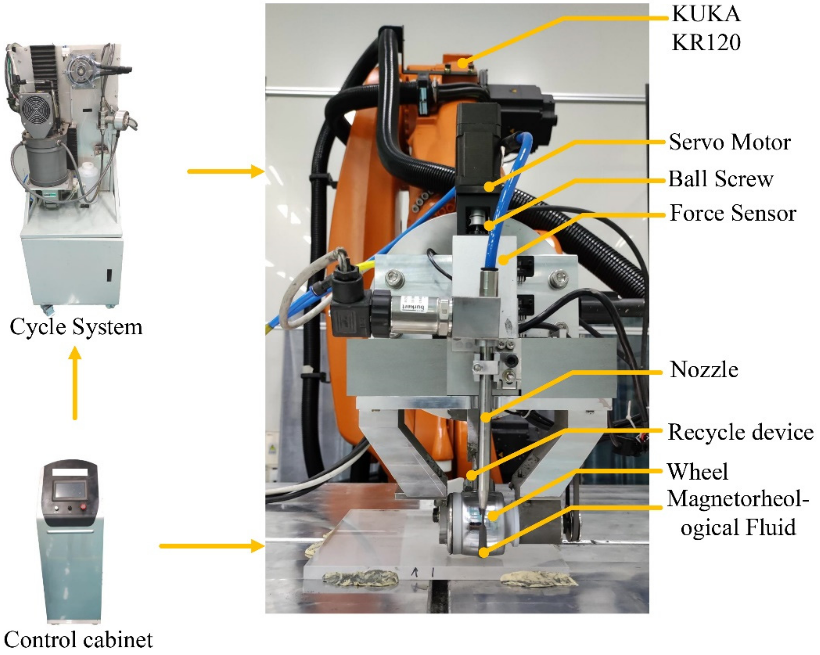
The experimental system includes a KUKA KR120 six-axis industrial robot arm and the proposed end-effector as shown in Figure 8. The polishing wheel speed is 500 rpm with a diameter of 50 mm. A kind of magnetorheological fluid with Nano-diamond is used in this experiment. The magnetorheological flowrate is 800   mL / min , and the ribbon height is adjusted to 2 mm.
The experiment is arranged as follows: First, verify the performance of the designed controller with several tests. Second, compare the robotic magnetorheological finishing stability before and after the constant force control. Third, conduct a mirror deterministic polishing experiment to verify the effectiveness of the proposed system. In all experiments, the six-axis robot carries the end-effector in vertical contact with a workpiece of quartz mirror (200 mm × 200 mm × 10 mm). The normal force F n during the polishing process is monitored and recorded by the application based on the software LABVIEW.

4.1. Constant Force Control with ADRC

This experiment is performed to validate the performance of the proposed system. The system response performance experiment is conducted under two different polishing forces. Figure 9 depicts the ADRC controller’s force response at the desired force of 1 N without disturbance. The force control system attains the intended force of 1 N after 450 ms of adjustment time and oscillates around 1N. The average force is 1.01 N, with the highest inaccuracy of 0.1 N in force control. Figure 10 depicts the force response at the intended force of 2 N during the dynamic process with the disturbance caused by robot positioning inaccuracy at 14.3% magnetorheological moisture. The force rises in 910 ms from 0.5 N to 2 N without overshooting, has a peak error of less than 0.3 N, and has an average force of 1.98 N. Figure 11 depicts the force response at the desired force of 2N during the dynamic process with the disturbance caused by robot positioning error at 15.3% magnetorheological moisture. The time of force to increase from 0.5 N to 2 N is 735 ms with a 0.1 N overshoot. The force control peak error is less than 0.3 N, and the average force is 1.96 N. As shown in the results, the system provides a quick response to disturbance and stabilizes it.

4.2. The Stability of Magnetorheological Polishing with Constant Force Control

To clarify the influence of F n on the stability of the removal function and to explain the influence law of the normal error on MRF volumetric removal rate, the spots for different forces are taken with the magnetorheological moisture 14.3 % and 15.3 % respectively.
The results of the correlational analysis are presented Figure 12. There is a positive linear correlation between F n and VRR that is consistent with the theoretical formula. The VRR increases as the water content decrease, and the coefficient of friction (i.e., the linear slope), also increases as the moisture decreases. From Figure 12 for the polishing force of 2 N commonly used, each unit normal force results in the VRR fluctuation from 1.6909 × 10 4   mm 3 / s to 2.1399 × 10 4 mm 3 / s , and the relative error of VRR reaches 40–50%.
The removal effect before and after constant force control on a 200 mm × 200 mm ×10 mm fused silicon mirror is analyzed using uniform polishing. The six-axis robot drives the polishing head to maintain the normal contact with the workpiece and processes the whole workpiece surface under 14.3 % moisture of MRF fluid. The polishing path is faster with 0.8 mm path pitch and the feed rate keeps constant. Figure 13a,b respectively shows the distributions of the normal polishing force and material removal amount without constant force control. From those, before compensation, the robot motion error causes uneven polishing at each point of the workpiece, and the material removal distribution is essentially the same as the normal force error distribution.
Figure 13c,d respectively reveals the distributions of the normal polishing force and material removal amount with constant force control. From those, after compensation, the constant force actuator effectively ensures the constant normal polishing force, with a peak error of less than 0.3   N and an average error of less than 0.05   N . The uniform removal distribution error of the material in the constant force polishing process is less than ±   0.05 λ ( λ = 632.8   nm ) . Hence, the developed constant force system plays a significant role in high-precision and high-efficient polishing.

4.3. Deterministic Magnetorheological Polishing with Constant Force Control

A fused silicon mirror with the size 100 mm × 100 mm × 10 mm is deterministically polished under 14.3 % moisture of the magnetorheological fluid. The raster polishing path is adopted with 0.8 mm path pitch, and the polishing feed rate is computed through the dwell time algorithm of deterministic polishing. The surface after robotic magnetorheological finishing is yielded, as illustrated in Figure 14. The RMS is reduced from 0.035   λ to 0.012   λ , and the peak error is reduced from 0.20   λ to 0.09   λ within 95% optical aperture ( Φ 95   mm ) .

5. Conclusions

The sensitivity of the magnetorheological removal function with the normal positioning error is investigated. Treating the normal polishing force as the monitoring target, a constant force polishing magnetorheological end-effector is designed, which has a fast response speed, high force control accuracy, compact structure, and lightweight. The impedance-based controller fulfills the force control stability and tracking precision. The adaptability of the magnetorheological end-effector is enhanced by the autonomous control system, and the robotic MRF method based on constant force control is applicable to any robots with different positioning precision levels.
The experimental results reveal that the normal force of magnetorheological polishing accurately defines the stability of removal function, and the distribution of material removal amount for the uniform polishing achieves high consistency under constant force control. The average error of constant force control reaches within 0.1N. A deterministic polishing based on constant force control is also conducted, and the results reveal that magnetorheological finishing with constant force has a strong surface convergence effect, which can satisfy the demands of nano-level surface fabrication for optical lenses.

Author Contributions

Conceptualization, C.Z.; writing-original draft preparation, L.Z.; writing-review and editing, L.Z., C.Z. and W.F. All authors have read and agreed to the published version of manuscript.

Funding

The research is supported by National Natural Science Foundation of China (61605182), Innovation Development Foundation of China Academy of Engineering Physics (K1267-2022-TCF).

Institutional Review Board Statement

Not applicable.

Conflicts of Interest

There is no conflict of interest.

References

  1. Shujing, S.; Jinfei, H.; Hequan, Z. New Progress of Magnetorheological Finishing. Mech. Eng. 2018, 7, 5–8. [Google Scholar]
  2. Chunlin, M.; Lambropoulos, J.C.; Jacobs, S.D. Process parameter effects on material removal in magnetorheological finishing of borosilicate glass. Appl. Opt. 2010, 49, 1951–1963. [Google Scholar]
  3. Ci, S.; Yifan, D.; Xiaoqiang, P. Model and algorithm based on accurate realization of dwell time in magnetorheological finishing. Appl. Opt. 2010, 49, 3676–3683. [Google Scholar]
  4. Zhichao, D.; Haobo, C.; Hon-Yuen, T. Modified dwell time optimization model and its applications in subaperture polishing. Appl. Opt. 2014, 53, 3213–3224. [Google Scholar]
  5. Lu, H.; Hua, D.; Wang, B.; Yang, C.; Hnydiuk-Stefan, A.; Królczyk, G.; Liu, X.; Li, Z. The Roles of Magnetorheological Fluid in Modern Precision Machining Field: A Review. Front. Mater. 2021, 8, 147. [Google Scholar] [CrossRef]
  6. Wei, T.; Jiao, J.C.; Li, B. Overview of high-precision operation equipment and technology for aerospace manufacturing robots. J. Nanjing Univ. Aeronaut. Astronaut. 2020, 52, 341–352. [Google Scholar]
  7. Belchior, J.; Guillo, M.; Courteille, E.; Maurine, P.; Leotoing, L.; Guines, D. Off-line compensation of the tool path deviations on robotic machining: Application to incremental sheet forming. Robot. Comput. Integr. Manuf. 2013, 29, 58–69. [Google Scholar] [CrossRef] [Green Version]
  8. Klimchik, A.; Pashkevich, A.; Chablat, D.; Hovland, G. Compliance error compensation technique for parallel robots composed of non-perfect serial chains. Robot. Comput. Integr. Manuf. 2013, 29, 385–393. [Google Scholar] [CrossRef] [Green Version]
  9. Xiaojia, S.; Zhang, F.M.; Qu, X.H.; Liu, B.L.; Wang, J.L. Position and Attitude Measurement and Online Errors Compensation for KUKA Industrial Robots. J. Mech. Eng. 2017, 53, 1–7. [Google Scholar]
  10. Zhu, D.; Feng, X.; Xu, X.; Yang, Z.; Li, W.; Yan, S.; Ding, H. Robotic grinding of complex components: A step towards efficient and intelligent machining—Challenges, solutions, and applications. Robot. Comput.-Integr. Manuf. 2020, 65, 101908. [Google Scholar] [CrossRef]
  11. Yu, Z.; Lin, H.-I. Development of robotic polishing/fettling system on ceramic pots. Int. J. Adv. Robot. Syst. 2021, 18, 17298814211012851. [Google Scholar] [CrossRef]
  12. Brecher, C.; Tuecks, R.; Zunke, R.; Wenzel, C. Development of a force controlled orbital polishing head for free form surface finishing. Prod. Eng. 2010, 4, 2–3. [Google Scholar] [CrossRef]
  13. Xuejun, Z.; Longxiang, L.; Donglin, X.; Chi, S.; Bo, A. Development and Application of MRF Based on Robot Arm. EPJ Web Conf. 2019, 215, 06001. [Google Scholar] [CrossRef]
  14. Li, L.; Zhao, C.; Li, C.; Qin, S. End Position Detection of Industrial Robots Based on Laser Tracker. Instrum. Mes. Métrol. 2019, 18, 459–464. [Google Scholar] [CrossRef] [Green Version]
  15. Wang, Z.; Liu, R.; Sparks, T.E.; Chen, X.; Liou, F.W. Industrial Robot Trajectory Accuracy Evaluation Maps for Hybrid Manufacturing Process Based on Joint Angle Error Analysis. Adv. Robot. Autom. 2018, 7, 1000183. [Google Scholar] [CrossRef]
  16. Zhu, J.M.; Qi, B.C.; Li, F.C.; Shen, Z.Q.; Li, X.R. Measurement of and Reverse Compensation for Spatial Position Error of Industrial Robots. J. Test. Eval. 2014, 43, 1221–1229. [Google Scholar] [CrossRef]
  17. Preston, F.W. The theory and design of plate glass polishing machines. J. Soc. Glass Technol. 1927, 11, 214–256. [Google Scholar]
  18. Shorey, A.B. Mechanisms of Material Removal in Magnetorheological Finishing (MRF) of Glass. Ph.D. Dissertation, Department of Mechancial Engineering, Materials Science Program, University of Rochester, Rochester, NY, USA, 2000. [Google Scholar]
  19. Chunlin, M.; Shafrir, S.N.; Lambropoulos, J.C.; Mici, J.; Jacobs, S.D. Shear stress in magnetorheological finishing for glasses. Appl. Opt. 2009, 48, 2585–2594. [Google Scholar]
  20. Bhushan, B.; Gupta, B.K. Friction, wear, and lubrication. In Handbook of Triboloty: Materials, Coatings, and Surface Treatments; McGraw-Hill: New York, NY, USA, 1997; Chapter 2; p. 2.11, Table 2. [Google Scholar]
  21. Pan, J.; Yu, P.; Yan, Q. Experimental Investigations on the Polishing Forces Characteristics of Dynamic Magnetic Field Magnetorheological Effect Polishing Pad. J. Mech. Eng. 2018, 54, 10–17. [Google Scholar]
  22. Schinhaerl, M.; Vogt, C.; Geiss, A.; Stamp, R.; Sperber, P.; Smith, L.; Smith, G.; Rascher, R. Forces acting between polishing tool and workpiece surface in magnetorheological finishing. In Optical Engineering + Applications; SPIE: San Diego, CA, USA, 2008; Volume 7060. [Google Scholar]
  23. Chunlin, M. Frictional Forces in Material Removal for Glasses and Ceramics Using Magnetorheological Finishing. PhD Thesis, University of Rochester, Rochester, NY, USA, 2009. [Google Scholar]
  24. Hogan, N. Impedance Control; An Approach to Manipulation, Parts I, II, III, ASME. J. Dyn. Syst. Meas. Control 1985, 107, 1–24. [Google Scholar] [CrossRef]
  25. Han, J.Q. From PID to Active Disturbance Rejection Control. IEEE Trans. Ind. Electron. 2009, 56, 900–906. [Google Scholar]
  26. Feng, D.; Xu, L. Transfer Function Identification. Part A: Two-Point and Three-Point Methods Based on the Step Responses. J. Qingdao Univ. Sci. Technol. Nat. Sci. Ed. 2018, 39, 1–14. [Google Scholar]
Figure 1. Taking spots under different immersion depths on a high-precision MRF machine. (a) MRF tool on a high-precision machine; (b) MRF ribbon when taking a spot; (c) The figure map after taking spots; (d) The distribution of the removal amount of MRF spot taking.
Applsci 12 03737 g001
Figure 2. Immersion depths and volumetric removal rate for MRF spots taken with a Nano-diamond MR fluid.
Applsci 12 03737 g002
Figure 3. Model of a magnetorheological polishing device with axial compliant force. (a,b) Main components of the end-effector; (c,d) Linear ball screw mechanism (all dimensions are in mm); (e) The MRF circulation system of the end-effector.
Applsci 12 03737 g003
Figure 4. Free body diagram of polishing tool and surface in normal direction.
Applsci 12 03737 g004
Figure 5. The system structure of force-controlled end-effector.
Applsci 12 03737 g005
Figure 6. Constant force control system with ADRC topology.
Applsci 12 03737 g006
Figure 7. Unit step response of ADRC and PID.
Applsci 12 03737 g007
Figure 8. Robot magnetorheological polishing platform with constant force actuator.
Applsci 12 03737 g008
Figure 9. Robotic magnetorheological polishing force response at 1N without disturbance.
Applsci 12 03737 g009
Figure 10. Robotic magnetorheological polishing force response at 14.3% magnetorheological moisture.
Applsci 12 03737 g010
Figure 11. Robotic magnetorheological polishing force response at 15.3% magnetorheological moisture.
Applsci 12 03737 g011
Figure 12. Volumetric removal rate and normal force with the moistures of MR fluid 14.3% and 15.3%.
Applsci 12 03737 g012
Figure 13. The normal force distribution and removal amount distribution with/without constant force control: (a) Normal force distribution of MRF process without constant force control; (b) The removal amount distribution without constant force control; (c) Normal force of MRF process with constant force control; (d) The removal amount distribution with constant force control.
Applsci 12 03737 g013
Figure 14. The error map before and after deterministic polishing with the force control: (a) Initial surface error map; (b) The residual surface error map.
Applsci 12 03737 g014
Publisher’s Note: MDPI stays neutral with regard to jurisdictional claims in published maps and institutional affiliations.