Article

Design of Cognitive Assistance Systems in Manual Assembly Based on Quality Function Deployment

by
Bastian Pokorni
1,*,
Daniela Popescu
2 and
Carmen Constantinescu
1
1
Fraunhofer IAO, Fraunhofer Institute for Industrial Engineering IAO, Connected Manufacturing Systems, Nobelstrasse 12, 70569 Stuttgart, Germany
2
Department of Design Engineering and Robotics, Faculty of Industrial Engineering, Robotics and Production Management, Technical University of Cluj-Napoca, B-dul Muncii 103-105, 400641 Cluj-Napoca, Romania
*
Author to whom correspondence should be addressed.
Appl. Sci. 2022, 12(8), 3887; https://doi.org/10.3390/app12083887
Submission received: 3 March 2022 / Revised: 2 April 2022 / Accepted: 8 April 2022 / Published: 12 April 2022
(This article belongs to the Section Mechanical Engineering)

Abstract

:
Increasing volatility and product individualization are leading to higher complexity in manual assembly. At the same time, production and processes must become more flexible, and humans have to adapt to new products more often and even faster. Industry 5.0 will increasingly focus on human-centric approaches, on the collaboration of humans and machines intensively using cognitive assistance systems. The design of an innovative cognitive assistance system is a complex task due to the many technological opportunities and their interrelationships. In the framework of this research, a method was developed enabling the systematic design of cognitive assistance systems that integrates business and worker requirements aiming at improving productivity, quality, worker satisfaction and well-being. The research question was approached by design science research having, as the main output, a systematic and innovative method for the design of cognitive assistance systems based on quality function deployment (QFD), referred to as cognitive assistance system-QFD (CAS-QFD). The developed methodology is divided into six phases and includes the iterative design of a cognitive assistance system starting from the assembly process. The method considers the information needs of the workers, the definition of the appropriate assistance functions and the selection of the interaction technologies. The exemplarily industrial evaluation highlighted the relevance of CAS-QFD for systematically designing cognitive assistance systems based on holistic requirements, identified at the worker, workplace, production area and, finally, at the enterprise level.

1. Introduction

Factories of the future will be connected by combining and integrating operation and information technologies [1]. There is a technology leap towards the fourth industrial revolution, also referred to as Industry 4.0 [2]. The digitization of production connects humans, machines and processes within cyber–physical systems or cyber–physical production systems [3], even along the entire value chain in real-time [4]. The term Industry 4.0 covers a wide range of technologies and applications, such as assistance systems, robotics and cobots, additive manufacturing, cloud computing, data mining, artificial intelligence, etc. [5], and follows the overall goal of enabling the manufacturing of highly individualized products at the cost of mass production [6]. Overall, Industry 4.0 is intended to make companies and their production systems more automated, efficient and flexible [7] while, at the same time, enabling them to expand their business model with smart products by digitizing parts of the products and developing new services [8].
At the same time, humans will remain an important part of the factory with their flexibility, intuition and creativity [9]. However, in the context of Industry 4.0, the role of workers in the factory is also changing significantly: workers collaborate with technologies in human–cyber–physical systems; i.e., they are assisted by systems in the qualification, execution and monitoring of more complex work processes [10,11,12]. This can increase process performance and transparency, the product/process quality and, in the best case, increase job satisfaction [13].
The new and evolved Industry 5.0 addresses this relationship between humans and technologies aiming at combining human intelligence with autonomous systems [14], focusing on aspects that have been given limited attention to date regarding the disadvantages for humans resulting from the more intensive use of information technology and automation in production activities [14,15]. In summary, Industry 4.0 is more technology-focused, while Industry 5.0 concentrates more on the human-centered perspective [16,17]. Industry 5.0 work systems can, therefore, be understood as a symbiotic collaboration between humans and machines [12] in which technology adapts to humans in an interplay and both follow shared goals. These assistance systems help people by overcoming skill gaps and try to increase social innovation, worker satisfaction and comfort [18,19].
Production processes and manual assembly processes will be needed in the future [20]. The challenge will lie in how the different workers (age, preferences, skills, etc.) can be supported by intelligent assistance systems [21]. Today, systems are already in use to support workers in assembly tasks by providing work instructions [22], notices about errors, performing automated quality checks [23], documenting process data [24] and more [25].
For the realization of the assistance functions, different technologies such as augmented reality [26,27,28], mobile devices [29], wearables [30,31,32], projection technologies [33,34,35], artificial intelligence [36,37,38] as well as different interaction modalities such as voice/speech, gesture/posture control, touchscreen and others are used [39].
These systems have already been validated, revealing that they have productivity advantages and that the workers are more satisfied [40,41,42,43,44,45,46]. This may also be related to the fact that the assistance systems can provide workers with greater autonomy to make their own decisions, or, furthermore, the systems can also be used to perform more challenging tasks and to focus on human strengths, such as communication, social behavior and the ability to work in a team [47]. On the other hand, it must be considered that people may be afraid of being replaced by technology or that they lose their autonomy and flexibility instead of increasing it in performing the work task and feel more controlled. This can reduce acceptance [48].
The challenge is represented in these situations by the design and development of assistance systems that feature cognitive capabilities. The variety of technologies and configurations is extensive, and, at the same time, both the company’s requirements and the needs of the workers must be considered in the design process. Responsible engineers need to understand in detail what the worker needs and how this can be aligned with the company requirements [17]. This means that a stronger understanding of the socio-technical system, in this case, manual assembly, as a holistic system consisting of humans, technologies and processes, is necessary. Assistance systems must be individually adapted and designed to the specific context of use. Each work system and each work process requires a different assistance system, and each worker has subjective needs and requirements that the assistance system should fulfill. A research gap in the field of design of cognitive assistance systems is evident in the connection of worker and company requirements with the technical features of the systems. None of the known methods and models with the specific integration of user- or human-centered perspectives offer an approach to systematically transfer the identified company and worker requirements into features and configurations of cognitive assistance systems [45,49,50,51,52].
The overall objective of this work is to support engineers of cognitive assistance systems to technically specify and configure an optimal assistance system for specific use cases. For this purpose, a method based on quality function deployment was identified as a promising approach, which is introduced further on.

2. Literature Review

2.1. Manual Assembly and Complexity

Manual assembly can be defined as the sum of all operations for the assembly of parts with a geometrically determined shape performed by a human operator. This includes all work operations that physically change the assembly object and serve the value-added process of a product. Secondary assembly supports primary assembly by handling, checking or adjusting specific parts [53]. Manual assembly systems are part of the production system as sub-systems and can be defined as socio-technical systems [54]. Due to the high costs and efforts in manual assembly processes, companies are trying to automate them completely [55], but manual operations will remain important in the future as products become more complex and the number of variants increases in the context of individualization (mass customization) [6]. Especially, the number of product variants can be a reason against automation of processes due to the costs and the low flexibility [56]. Manual assembly processes are, therefore, characterized by their ability to respond flexibly, quickly and economically to changes [56,57].
Common design configurations of manual assembly systems are:
  • Single workstations (work is performed at one workstation and involves specific or variations of tasks and processes);
  • Continuous flow assembly systems (workpiece carrier flows from one station to the next without interruptions using assembly lines, each station being assigned to a specific task);
  • Intermittent assembly (multiple workstations are assigned to specific tasks; the product moves from one station to the next in fixed cycle times) [58].
The complexity of manual assembly processes depends on the number of product variants, on the parts variety [59] as well as the variant-specific operation time [60]. Additionally, product quantity, quantity variants and content of the information provided are dependable factors [61]. Doerr and Arreola [62] have enhanced the complexity with the variability of workers’ skills. The perceived complexity can be influenced not only by the individual skills but also by the competences and experiences [63] so that the structural view of process complexity is insufficiently determined [64].

2.2. Cognitive Assistance Systems

To understand the assistance systems approach, the human cognitive processes are defined as follows [65]: “Cognitive tasks are those undertakings that require a person to mentally process new information (i.e., acquire and organize knowledge/learn) and allow them to recall, retrieve that information from memory and to use that information at a later time in the same or similar situation (i.e., transfer).” To explain the human information processing, different models and approaches have been developed over the years, such as the skill-, rule- and knowledge-based behavior model (SRK-model) by the authors of Ref. [66], the system 1 and 2 model by the authors of Ref. [67], the theory of situation awareness by the authors of Ref. [68] and the human information processing model by the authors of Ref. [69].
Cognitive assistance systems are technical systems that process information and support humans in performing their tasks [70,71], enhancing the worker’s capabilities [72]. These systems provide to the worker the right knowledge and information in the right way and at the right time and can also comprise alarms of hazards, notifications, automatic intervention, documentation and control of the correct execution of work tasks in the assembly system [73,74,75,76]. Cognitive assistance systems support the following steps of the human information processing: task perception (detect and recognize), task decision (assess and generate) and task execution (export) [77]. Such systems consist of various components aiming at collecting, processing, storing and evaluating data and information. This creates a human–computer interaction so that feedback to the user can be provided and his/her processes can be monitored and controlled according to the task goal [78]. In manual assembly, these systems provide work instructions, bill of materials, drawings, special information, etc. [79], using technologies such as stationary monitors, mobile devices, wearables or augmented reality [80,81].
Cognitive assistance systems can be differentiated in their level of automation [82]. These start with completely manual processes up to automated self-learning systems (see Table 1).

2.3. Qualtity Function Deployment

Quality function deployment (QFD) is used for customer-oriented development of products and was introduced by Yoji Akao in 1966 [83], being frequently used in almost every industrial sector. The basic approach is based on the separation of product features and customer requirements. These are usually correlated [84]. One of the goals of QFD is to systematically integrate in the product development process different perspectives (interdisciplinary QFD-teams) and knowledge from different disciplines [85].
The classical approaches for QFD are the Akao approach, four-phase approach (American Supplier Institute approach) and the matrix of matrices approach. The four-phase approach is defined in Ref. [84] as a set of matrices with defined inputs and outputs (see Figure 1). The first phase involves the translation of customer requirements into measurable quality characteristics. The second phase translates the quality characteristics into components and parts of the product. At the end, these elements are prioritized based on the degree of fulfillment of the required quality characteristics. In the third phase, the manufacturing processes and specifications, which, in the fourth phase, are defined as work instructions, control plans and training requirements necessary for realization [86,87,88,89,90], are prioritized.
The starting point is the house of quality, where the customer requirements (WHAT—voice of the customer), quality characteristics (HOW—voice of the engineer), planning matrix, correlations between customer requirements and quality characteristics, interactions between the quality characteristics and the technical objectives are clearly collected [90,91].
There are numerous methodological adaptations for different application areas such as product development, quality management, product design, management, software engineering and service engineering [92,93,94,95,96,97].

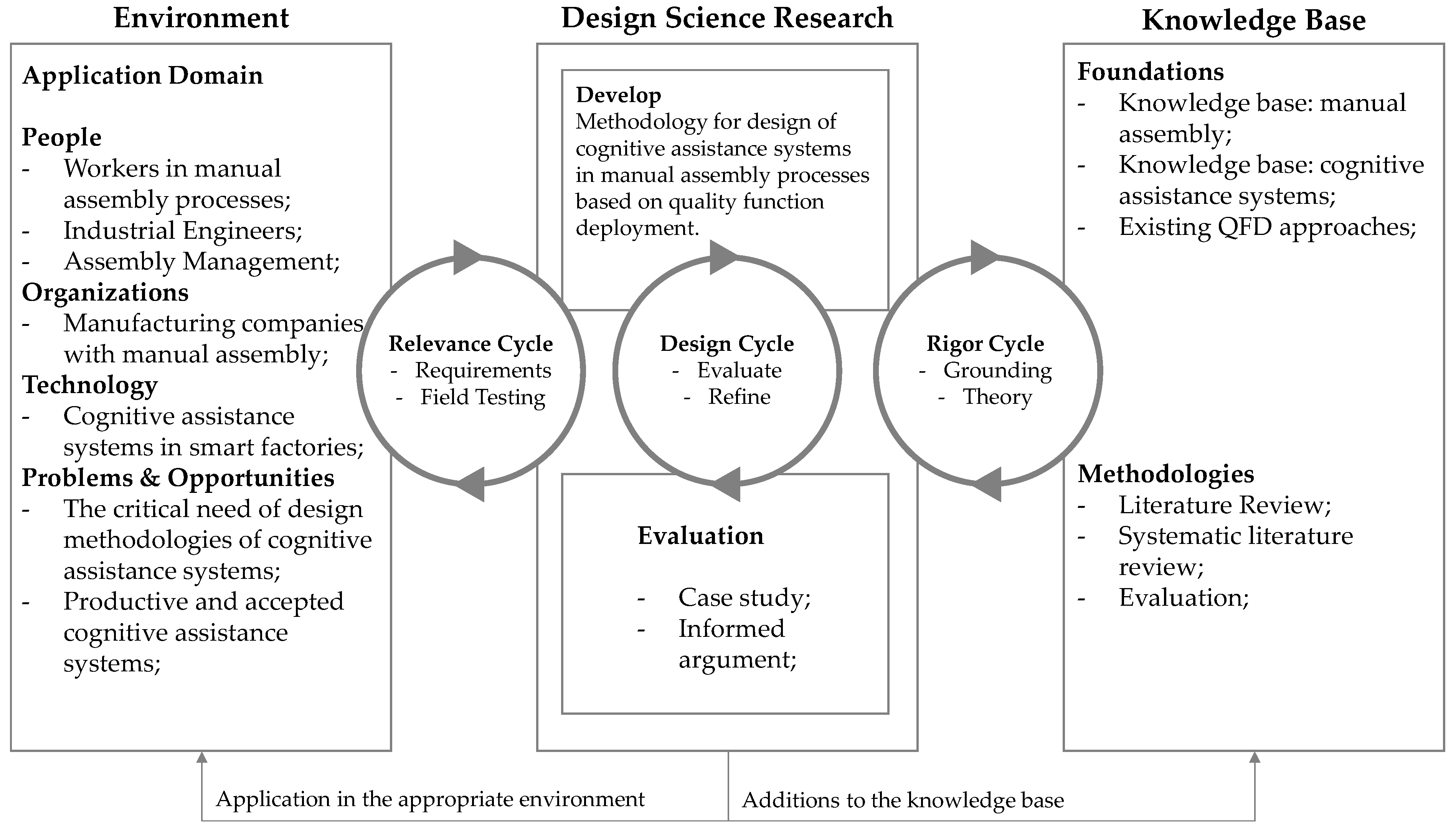
3. Foundations and Methods

This research approach to design and configure a cognitive assistance system in manual assembly is based on an adapted QFD methodology, further on defined in our work as “cognitive assistance system-QFD (CAS-QFD)”. The presented gap in studied literature and current research leads to the questions as to how: (research question 1) a systematic approach for the design and configuration of cognitive assistance systems for manual assembly processes can be implemented by using an adapted QFD approach; (research question 2) such an approach and its relevant design attributes have to be adapted with the prerequisites that future users of the assistance systems are included as well as the company’s requirements; (research question 3) an assembly process can be investigated and assistance system’s potential can be identified; (research question 4) the determined assistance system potentials can be correlated and specific steps for realization can be implemented.
The research questions lead to the following solution hypotheses:
  • The application of QFD enables the structured documentation of requirements as well as the derivation of assistance potentials and their systematic design;
  • The clear differentiation between design attributes and the systematic design of these attributes enables a structured approach by means of the QFD method.
The research objective is to explore whether the QFD method is suitable for the design of cognitive assistance systems in manual assembly processes. Based on existing systematic procedures, the QFD method is to be modified so that cognitive assistance systems can be systematically designed. For this purpose, the crucial design attributes will be determined and, if necessary, these will be made measurable.
To answer the research questions and develop the objectives according to scientific methods, our work follows the design science research methodology (DSRM) [98] as shown in Figure 2. Design science originates from the field of information systems. The focus of the design science research approach is on the development of artifacts to solve practical problems. The developed artifacts can be constructs, models, methodologies or instantiations. The research question includes the need for a methodology to be an artifact in the sense of design science.
Table 2 illustrates the procedure followed in our work. For each step, methods and results are defined.
The evaluation of an artifact can be completed in different ways. In the following Table 3, based on Refs. [98,99,100], the various types are listed. For the presented research of a new or adapted method, an empirical evaluation, such as technical experiments, case studies or scenarios, is suitable [99]. For this reason, the application of the new method is evaluated in this paper using a case study and informed argument. The main evaluation criteria are operationality, efficiency, generality and ease of use [101].

4. Conceptual Adaptation of the QFD Method

4.1. Suitability of the Method

To evaluate the suitability of the QFD method, the focus of the design process and the objectives of the method are explained and defined at this point. For this purpose, the research questions and objectives already defined are further detailed as a basis.
Subjects of the design are cognitive assistance systems, and central design aspects are to determine the level of assistance, the information provision, the interaction modalities between worker and system as well as the output and input hardware.
The method should enable the analysis of the underlying assembly process to obtain as holistic a system as possible and to understand the context of the work process. The method should also be able to support a make or buy decision regarding market-available assistance systems and ensure the participation of the workers within the design process. The method should also be able to correlate business and worker requirements with assistance functions and interaction modalities. In addition, the interaction modalities should be able to be considered and aligned with the information content for the worker as well as the influences of the work environment on the modalities.
In summary, the design task includes the consideration of an assembly process, as is carried out in process-QFD, e.g., for service processes, the selection of hardware and human-machine interaction as they are already used in conventional QFD approaches as well as in software-QFD applications. Thus, basic application of the QFD approach is given and can be adapted and designed as a participatory process for the design of cognitive assistance systems.
In our case, customer requirements mean requirements of the workers and the company, and quality features are defined as the assistance functions or the interaction modalities. For this purpose, six phases instead of four phases are chosen, which an interdisciplinary team can follow. In contrast to conventional QFD applications, additional areas have to be integrated into our approach, e.g., the determination of the amount of information, the environmental influences from the work area, etc.
The participation of the workers allows to record requirements and discuss design issues in each step of the design process. This should ensure that the system fits the work task and thus also increase user acceptance.
Unchanged to known QFD applications, correlation logic, weightings, requirement prioritizations and the typical calculation procedures as well as the interaction of the elements among each other shall be adopted in the present application.
The relevant adjustments to the known QFD approaches can be found in the following chapters.

4.2. A New Proposed Conceptual Approach: Cognitive Assistance System-QFD

The CAS-QFD method is based on six phases and step-by-step application (Figure 3). The approach is based on QFD derivatives, such as the software-QFD, process-QFD and service-QFD, as proposed by the authors of Refs. [102,103,104,105,106,107,108], and our novel conceptual approach [109].
In the first phase, the overall goals and future challenges of the company are identified. It is important to understand these to be able to make the later weightings and decisions. The material flow and the production IT-systems inside the company’s IT landscape are also considered. Since the production system, assembly configuration and their workers (experience level, age, preferences, etc.) are important for the design of the assistance functions and hardware, they are also analyzed. Finally, the project definition is created.
For the design of an assistance system, the process in which the assistance functions are provided should first be analyzed, because of strong interrelationships, in second phase. In the sense of a process-QFD, requirements for the assembly process demanding assistance and the specific assembly tasks could be integrated and correlated in the first phase. The requirements of the assembly workers should also be included at this stage. The objective is to identify which requirements are related to which process steps and in what context so that an initial understanding of the assembly process is developed.
In the third phase, suitable assistance functions are identified for the prioritized work tasks that need to be optimized. In this process, specific requirements of the workers can be identified and considered in the design of the assistance functions. In this way, the most important parts of the assembly process can be determined for optimization with the relevant assistance functions (assistance level).
In the fourth phase, suitable hardware components can be defined for the specific assistance functions. This involves the human–assistant interaction. Furthermore, the interrelationships between the hardware components should be considered. The user requirements can again be considered in this phase for the design.
In the fifth phase, the favored product variant is prototypically built and manually tested. This allows hypotheses to be validated and incremental changes to be performed before the system is implemented in the sixth phase, where it is finally evaluated and transferred into operation. A retrospective on the collaboration and the quality of the results concludes the project. The participation of the workers is proposed from phase two to the final realization.
The phases and the included steps should not be understood as a pure assessment tool. Instead, with the help of the developed logic for the design of cognitive assistance systems, it should offer the possibility of finding suitable alternatives through iterations of multiple trials. For this purpose, the steps can also be executed in a different order or can even be examined in parallel to each other.

4.3. Development of the Cognitive Assistance System-QFD (CAS-QFD) Method

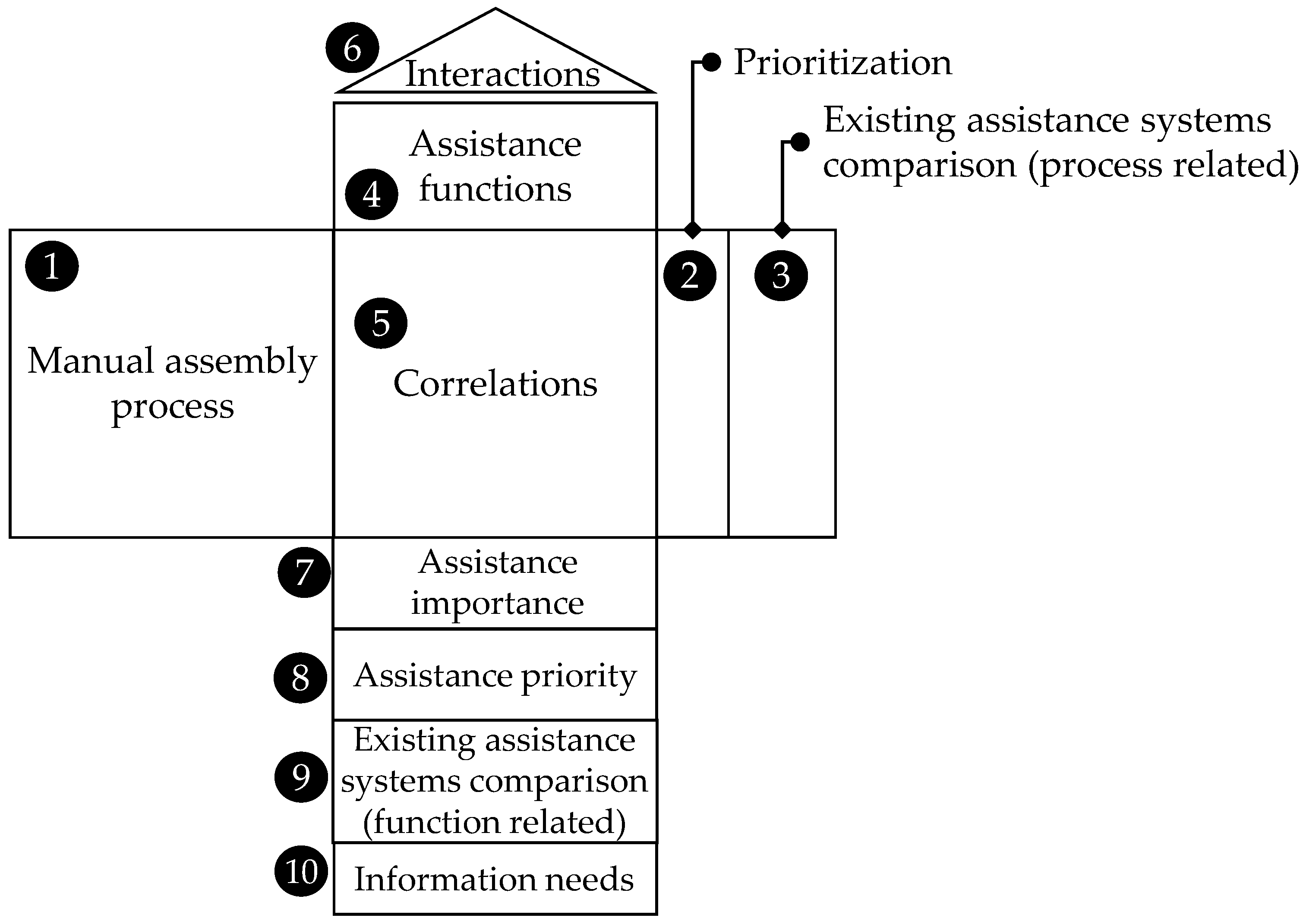
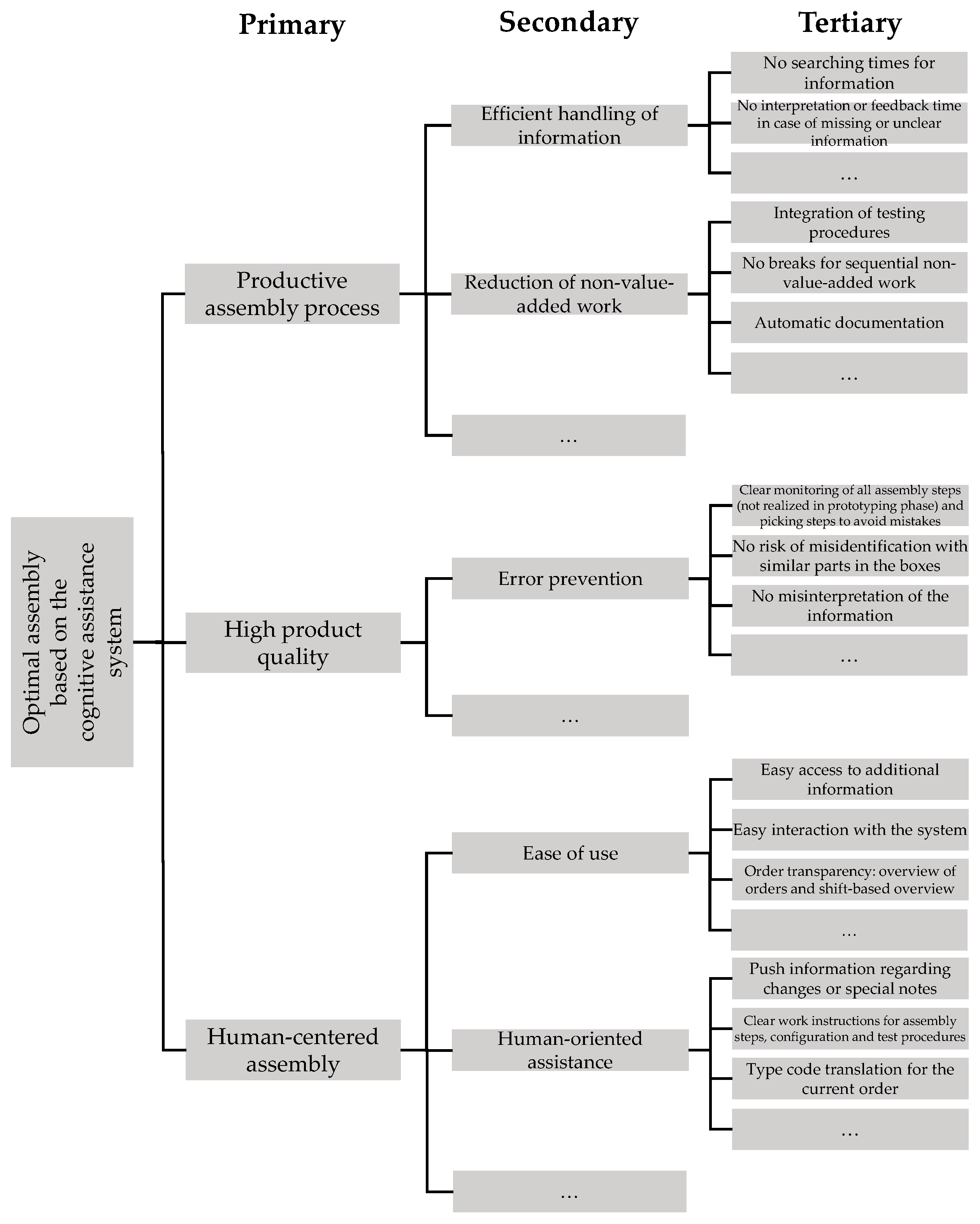
4.3.1. Analysis of the Manual Assembly Process and Identification of Requirements

Figure 4 shows the conceptual structure of the second phase of the CAS-QFD method. In the following, the individual steps as numbered in the figure are explicitly explained.
First, the requirements of the workers and the company are identified (step 1, Figure 4). These relate to the assembly process. The actual identification of the requirements can be carried out deductively or inductively in an initial step using suitable methods. The requirements identified are weighted (step 2, Figure 4), for example, by means of a pairwise comparison and ranked by relative values. The fulfillment of the requirements for the assembly process is compared with other companies in a competitive comparison (scale: –2, –1, 0, 1, 2) (step 3, Figure 4). This contributes to defining a realistic assessment. Then, the optimization importance of the requirements is calculated (step 4, Figure 4). This is related to the specific need for action and can be calculated through following equation:
o i = d i c i
o i is the weighted optimization importance value; d i is the degree of relative importance of the worker and company requirements; c i is the competitive comparison value.
Now, the assembly process and the work tasks within the assembly process are defined (step 5, Figure 4). The process is modeled in advance using suitable methods (e.g., value stream mapping, precedence graph). The correct level of detail for capturing the requirements and assistance functions must be determined. In the house of quality, the interdependencies/interactions of the process elements are analyzed and the strength of the influence is defined (step 6, Figure 4). Knowledge of the interactions is important for the subsequent design of the assistance functions since the interactions of the process elements also cause the interdependencies of the assistance functions and cannot be considered isolated. Process control is graded in comparison to the competition (scale: 1 = very good to 5 = insufficient) (step 7, Figure 4). This allows the potential for optimization to be derived. The correlation between process elements and requirements is performed in the next step (step 8, Figure 4). For this purpose, the correlations must be identified and weighted (Table 4). This identifies the process elements that have the greatest influence on the satisfaction of workers and the company.
The individual correlations (influence values) are multiplied by the optimization importance values (step 9, Figure 4).
w j = i = 1 n o i r i , j
w j represents the value for the process importance of each manual assembly process step; r i , j is the influence coefficient between the ith user and company requirements and the jth manual assembly process steps.
In the next step, the optimization priorities of the process elements are calculated (step 10, Figure 4):
p j = w j c j
p j represents the optimization priority value for each manual assembly process step; c j is the value for process control.
If the process element achieves good quality values regarding the process control, less optimization is required related to the process. Based on the absolute optimization priorities, the relative optimization priorities can then be calculated, which relate the absolute values with the overall optimization project. This makes it clear in which relative relationship the optimization of a process element relates to other sub-processes.
Relative prioritization p j * :
p j * = p j 100 j = 1 m p j
This indicates that the process element with the highest relative optimization priority has the highest optimization potential, while, at the same, time considering a high influence on worker and company satisfaction and process control.
A simple weighting of the relative optimization priorities shows the ranking of the entire optimization, whereby the process element with the highest weighting should be optimized first.
Weighted prioritization p j w * is calculated as follows:
p j w * = p j 10 j = 1 m p j *
The results of the house of quality are optimization priorities that, by systematically linking the company and worker requirements with the process elements, reveal the optimization potential of the company’s own processes. Well-founded measures can be derived and specified for these in the following phases.

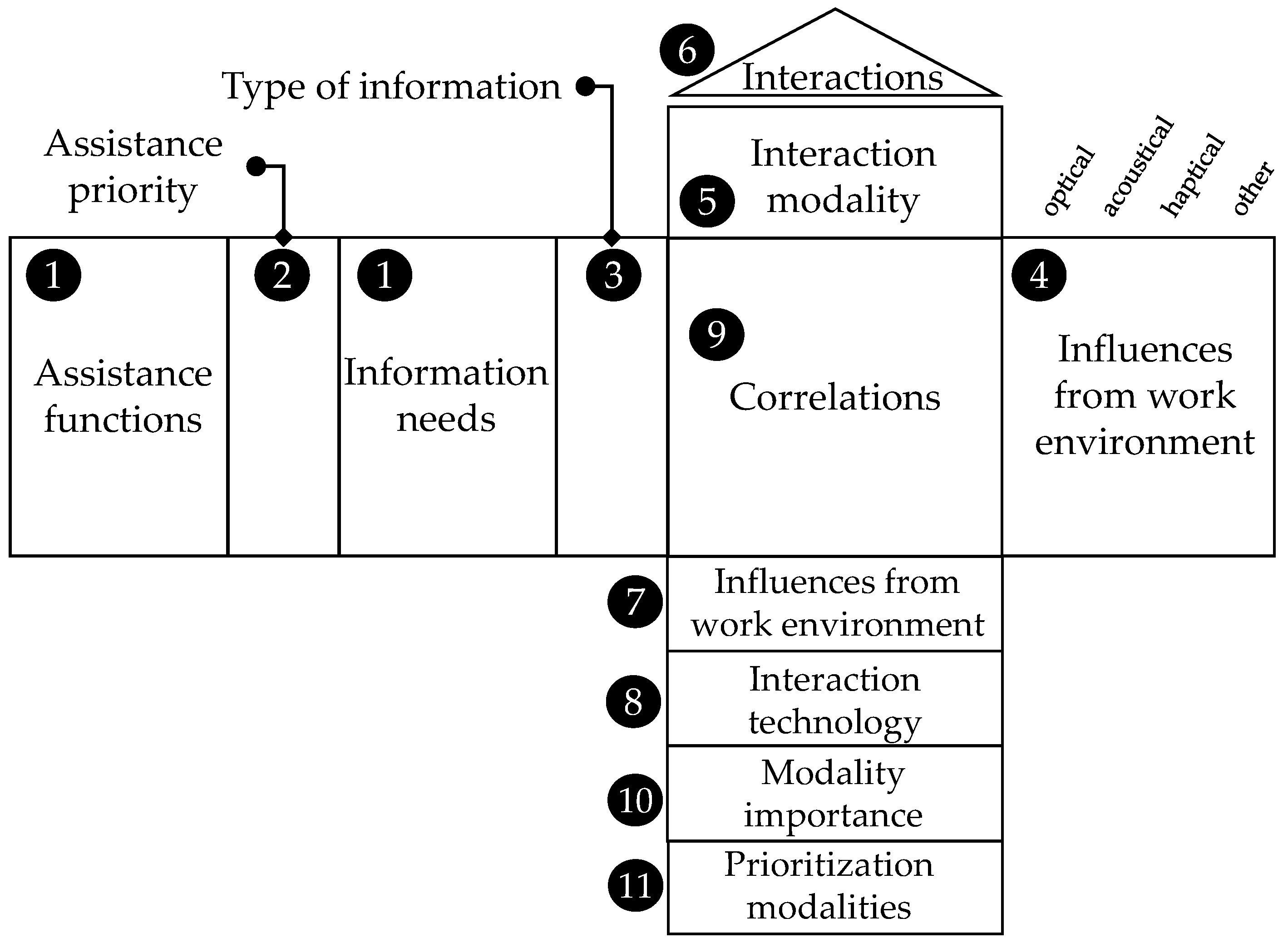
4.3.2. Assistance Concept Design

Figure 5 shows the conceptual structure of the third phase of the CAS-QFD method. All steps are numbered as shown in the figure and explained in the following section.
In this phase (Figure 5), the optimization potentials of house of quality are considered in the context of an assistance system development, and actions for assistance are defined. For this purpose, suitable assistance approaches are identified based on the requirements resulting from the process elements to support the manual assembly processes.
The process elements are first transferred line by line (step 1, Figure 5). The holistic assessment is significant because the subsequent cognitive assistance system relates to the entire process and does not exclusively affect isolated individual steps. The weighted prioritization values are also transferred (step 2, Figure 5). In the later design of assistance functions, these are relevant for determining which subprocesses must be focused on for a potential assistance function. In the next step, the fulfillment levels (scale –2, –1, 0, 1, 2) of various assistance functions available on the market are compared regarding their support of the company’s own processes (step 3, Figure 5). The analysis reveals whether typical assistance functions already meet the requirements regarding assistance functions to a sufficient degree or if a specific assistance system should be designed. The assistance functions/assistance levels (see Table 1) can now be defined (step 4, Figure 5) based on Refs. [82,110]. The objective represents the optimization of relevant process elements and work tasks based on the identified requirements. In this way, a first assistance construct is created, which will be detailed in the following steps.
As the separately identified assistance functions can also be interrelated with other process elements, to evaluate how process elements are influenced by assistance functions to show the degree of support represents an important action. The fifth step involves correlation, i.e., the linking of process elements with assistance functions (step 5, Figure 5). In the next step, the identified assistance functions are evaluated for interactions (step 6, Figure 5). For this purpose, each assistance function is compared individually with each other and the dependency is defined. The identification of relationships and dependencies provides a first indication of the framework in which the assistance functions can act in relation to each other. A possible aggregation of the assistance functions, i.e., the merging and combining of functions, can thus be initiated by the design team. The relationships between process elements and assistance functions weighted in step five are calculated in this step (step 7, Figure 5).
The calculation results in the importance of each individual assistance function:
a k = j = 1 n p j w * r j , k
a k is the value for the assistance importance of each assistance function; r j , k is the influence coefficient between the jth manual assembly process steps and the kth assistance function.
The values combined in this manner represent the importance of the individual assistance functions in the assistance system, considering the process elements. Based on the calculation of the importance of each individual assistance function, the assistance priorities can be calculated and the ranking of the assistance functions to be implemented can be determined (step 8, Figure 5). For this purpose, the individual importance is set in relation to the sum of all importance of measures. In this way, the percentage share of an assistance importance in the entire assistance construct is determined as a k * :
a k * = a k 100 k = 1 n a k
These values can be ranked and prioritized by the highest and can be further weighted.
Weighted prioritization a k w * is determined by equation:
a k w * = a k 10 k = 1 n a k *
In the next step, a competitive comparison (values −2, −1, 0, 1, 2) of available assistance systems is made regarding their performance in terms of functionality (step 9, Figure 5). Positive ratings indicate good fulfillment of the required functions. In the last step, the specific information needs (work instructions, BOMs, drawings, etc.) for the worker can be defined for the specific assistance function defined (step 10, Figure 5).
The result of this stage is assistance priorities, which identify the assistance potential of the company’s own processes by systematically linking the process elements with the assistance functions. These can be further specified in the next phase. The assistance concept that has been developed reveals the functions that should be implemented. Based on the defined priorities, it can be decided to what extent a cognitive assistance system should be implemented.

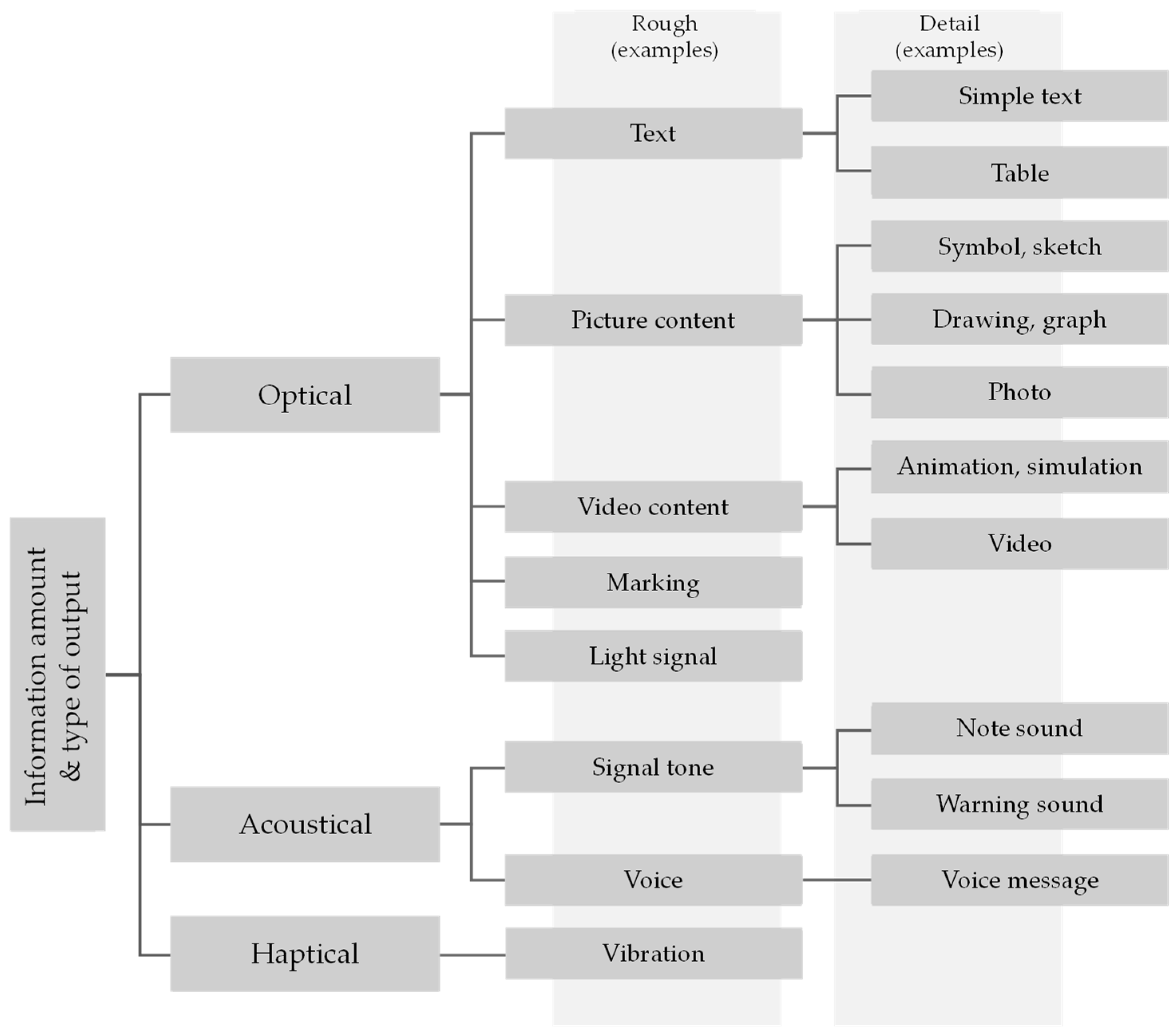
4.3.3. Assistance Detail Design

Figure 6 shows the conceptual structure of the fourth phase of the CAS-QFD method. In the following section, all steps are explained in detail.
In the two previous phases, process elements of manual assembly were analyzed, and the possible assistance potential was defined. As one of the design attributes of the cognitive assistance system, initially, only the assistance functions were considered to enable its complex planning step by step. The detailed design of the interaction touchpoints, together with the other design attributes of the assistance system, will be determined in this phase (Figure 6).
In the first step, the assistance functions are captured line by line together with their information needs from the previous step (step 1, Figure 6). Because the assistance functions were synchronized with their information needs in the previous step, it is sufficient at this point to include only the assistance functions that are relevant for the cognitive assistance system. In the same way, the assistance priorities are transferred from the previous phase (step 2, Figure 6). In the later definition of interaction modalities, these are relevant to determine which sub-functions must be considered, primarily in the case of possible assistance.
The next step is to define the type of information the worker will be provided with (step 3, Figure 6). This is the basis for the later definition of the interaction modalities. Based on Refs. [74,111,112,113,114], Figure 7 illustrates how the different types of information and information objects can be structured.
The information needs are analysed for influences from the work environment according to the system developed (step 4, Figure 6). For this purpose, each information need is brought together with the various influences from the work environment based on its type of information and evaluated according to their relationship intensity (Table 4). This can indicate possible conflicts in the choice of interaction modalities. There are many different influences on the working environment. Some influences can be modified, while others are unchangeable. Based on the modalities, possible disturbing influences of the working environment are presented in Figure 8.
In the fifth step, the interaction modalities for the relevant assistance functions are defined (step 5, Figure 6). The selected modalities are designed to make the subfunctions realizable and, therefore, the assistance function possible. Consequently, individual interaction modalities are defined for each assistance function together with its information need and type of information (Figure 9 and Figure 10 based on Refs. [74,111,112,113,114]). In this way, the assistance concept becomes a feasible assistance system based on interaction modalities.
The dependencies and interactions are examined in the next step (step 6, Figure 6). For this purpose, each interaction modality is compared with the others and the intensity of the interdependence is assessed. Now, it can also be checked how different information needs relate to the modalities and whether there are advantages in simplifying or combining modalities. The result indicates how the individual modalities must interact with each other. Then, the influences of the working environment on the interaction modalities are analysed (step 7, Figure 6). Each interaction modality is assessed for existing influences of the working environment and their strength of influence. Based on the analysis, suitable specific technology components are defined in the eighth step (step 8, Figure 6).
Finally, the correlation of assistance functions with the interaction modalities follows, whereby their dependencies must be identified and weighted to make a final statement about priorities of the interaction modalities. The interaction modalities are interrelated to the information needs of the assistance functions. At this point, it is necessary to evaluate how these are interrelated (step 9, Figure 6). In step six, the dependencies of the interaction modalities on each other were shown and a first link to information needs was made. In the ninth step, the correlation, i.e., the linking of interaction modalities with information needs or assistance functions, is performed. The result shows the most important interaction modalities for the worker as well as the modalities that have the greatest influence on the most important assistance functions, process elements and, therefore, on company and worker satisfaction. It allows a holistic view of interaction modalities and the associated assistance functions. The modality importance is calculated in this step (step 10, Figure 6). The calculation results in the importance of each individual interaction modality. The values combined in this way represent the importance of the individual modality in the assistance system considering the assistance functions. This means that the interaction modality with the highest value in the column is the most important for the company and the worker, and, therefore, its influence has the greatest impact on overall satisfaction. The modality importance can be determined by following equation:
t h = k = 1 n a k w * r u , k
t h is the value for the modality importance of each modality function; r u , k is the influence coefficient between the uth interaction modality and the kth assistance function.
Based on the definition of the importance of each individual interaction modality, the priorities of these can be calculated in the next step (step 11, Figure 6) and the ranking of the interaction modalities for implementation can be defined. For this purpose, the individual importance is set in relation to the sum of all modalities’ importance. In this way, the percentage share of a modality importance in the entire assistance construct is determined as t h * :
t h * = t h 100 h = 1 n t h
These values can be ranked and prioritized by the highest and can be further weighted.
Weighted prioritization t h w * is determined by equation:
t h w * = t h 10 h = 1 n t h *
The result of this step is the emergence of priorities for interaction modalities, which show a possible implementation variant of the assistance priorities by systematically linking the assistance functions with the modalities. The refined assistance construct shows which modalities can be implemented holistically.
Based on the defined priorities, it can be decided to which extent the assistance system should be realized. Similarly, the effects and restrictions of excluding an interaction modality would be recognizable. The assistance construct represents the planning approach for a prototype.

5. Results

5.1. Evaluation Method

As already described in chapter 2, the evaluation of the new method was performed by a case study. This involves a specific problem from a company and has the goal of designing a new assembly workstation and the corresponding assistance system. The method was performed jointly by scientists and industrial engineers, IT-specialists and assembly workers of the company (six persons in total). The design of the assistance system using the method was completed in three workshops with five hours each (without prototype realization). The phases one to five (Figure 3) were performed.

5.2. Company Profile

For the evaluation, a manual assembly process of a leading flowmeter manufacturing company based in Germany was used (approximately 170 employees). The most important target markets are process industries, such as the oil and gas industry, the chemical and pharmaceutical industry and the food industry. Flowmeters are used to measure the mass flow, volumetric flow, density, concentration and temperature of liquids and gases. The products include different sensor product lines and converters, which can be configured according to specific application requirements and process conditions. This results in a large number of different variants for the company.
In this case, the assembly process studied is assembly of the measuring converters. This is a manual assembly process, without machines, and takes about 20 to 30 min (depending on the variant and size). The assembly is designed as two single assembly workstations with four assembly workers in two shifts (more than 15 workers are trained for this assembly operation).

5.3. Application of the CAS-QFD

5.3.1. Phase 1: Preparation

At the beginning of the project, a project team was formed and the project framework for the development and implementation of a cognitive assistance system was defined. The role of the measuring converter in the overall product portfolio has become increasingly important due to the development of the analysis functions required by the customer. Historically, this has resulted in a separate assembly area that focuses exclusively on the assembly of converters that attempts to cope with the constantly growing number of variants. Productivity suffers as a result of the large number of product variants.
The assembly process for converters is a critical process within the production processes controlled by Kanban cycles. The converter can be ordered either as a ready-to-ship device or as a complete device assembled with the sensor. An assembly order consists of the “standard production order” (SPO) resulting from the type code and the parts’ list.
For support, assemblers can use a paper-based assembly instruction that explains the individual work steps in detail. The assembly order is processed using barcodes via the barcode scanner. In addition to different measuring devices, tools and boxes for smaller parts, there are auxiliary devices, a zoom lamp and the work instructions (assembly instructions and other regulations) provided. The finished converters are finally placed on the shelf, on the right side, by the worker (Figure 11).
The assembly workers can be grouped based on their age and experience as follows:
  • Group 1: 70% of the assembly workers are semi-skilled workers between 26 and 52 years;
  • Group 2: 30% of the assembly workers are new employees/beginners between 20 and 25 years.
In summary, the first phase provided the project team with a concrete overview of the current state of manual assembly. This will be investigated in the following phase.

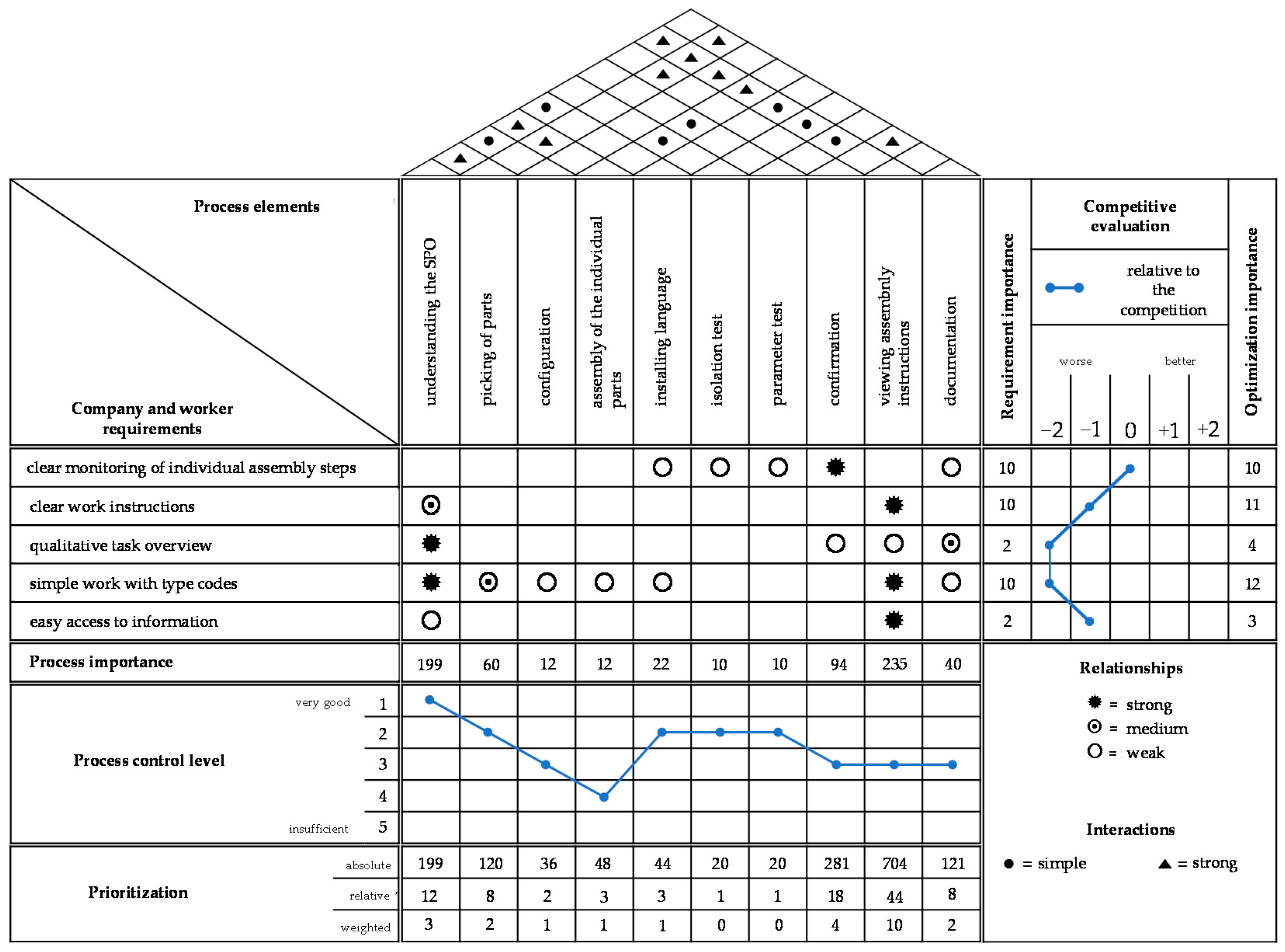
5.3.2. Phase 2: Analyzing Assembly Process

In the second phase, the assembly process was analysed according to the procedure described in Section 4.3.1. In the first section, the requirements were weighted, in the second section, process details were recorded and, in the third section, the requirements were linked to the process details.
First, we determined the requirements of the workers as well as the managers within the assembly. A semi-structured focus group discussion (120 min) was conducted with six workers from the assembly line, two industrial engineers and one manager afterwards. The aim of this discussion was to collect feedback concerning problems, ideas, suggestions and approaches for the assembly process. Based on these results, we defined the requirements at this point. The requirements were then weighted by the requirements’ owners using a pair-wise comparison. The highest ranked requirements were clear monitoring of individual assembly steps, clear work instructions, qualitative task overview, simple work with type codes and easy access to information. Figure 12 presents the functional and non-functional requirements as primary, secondary and tertiary requirements.
Based on the weighted requirements, a competitive comparison, which relates the fulfilment of the requirements with competitors, was performed based on existing and already realized case studies from other companies. Finally, the rank per requirement could be concluded.
According to the requirements’ definitions, the essential (summarized) assembly process steps (Figure 13) were transferred.
For a comprehensive investigation of the assembly process, a clear limitation is first necessary within the framework of process identification. For this purpose, the assembly process into tasks and sub-tasks was abstracted. Afterwards, the interactions between the process elements were determined. For example, it can be observed in Figure 14 that the process step for “understanding the SPO” has a strong dependency on the “assembly of the individual parts” and the “viewing the assembly instructions”. In concrete terms, this means that, if information changes during “understanding the SPO”, this influences the other process elements listed. This was followed by a critical assessment of technical process control as part of the sub-process analysis. For this purpose, the quality of task performance within a process from the company’s point of view was evaluated. The results show that the step “assembly of individual parts” is only adequately performed, whereas “understanding the SPO” is performed very well. The assessments were defined through key performance indicators research and sample-based process observations. At this point, the requirements were matched with the identified process elements. For this purpose, the project team considered interactions in a two-dimensional matrix that shows which requirements are influenced by which process elements and to what intensity. In the correlation matrix, it can be seen that “understanding the SPO” and “viewing the assembly instructions” have a strong relationship to the requirements.
The process importance is relativized by the evaluation of the process control made before. Therefore, the “viewing of the assembly instructions” should be improved as a priority. It thus has the greatest impact on satisfaction. The interactions identified show that the process “viewing of assembly instructions” has a large amount of interdependencies with other process steps, so it does not seem reasonable to consider it individually. The design of an assistance system in relation to assembly instructions was, consequently, considered to be of crucial relevance to the process as a whole. In particular, the requirement “simple work with type key” achieved the highest requirement weighting, which had to be considered further in the subsequent design. The result of this phase is illustrated in Figure 14.

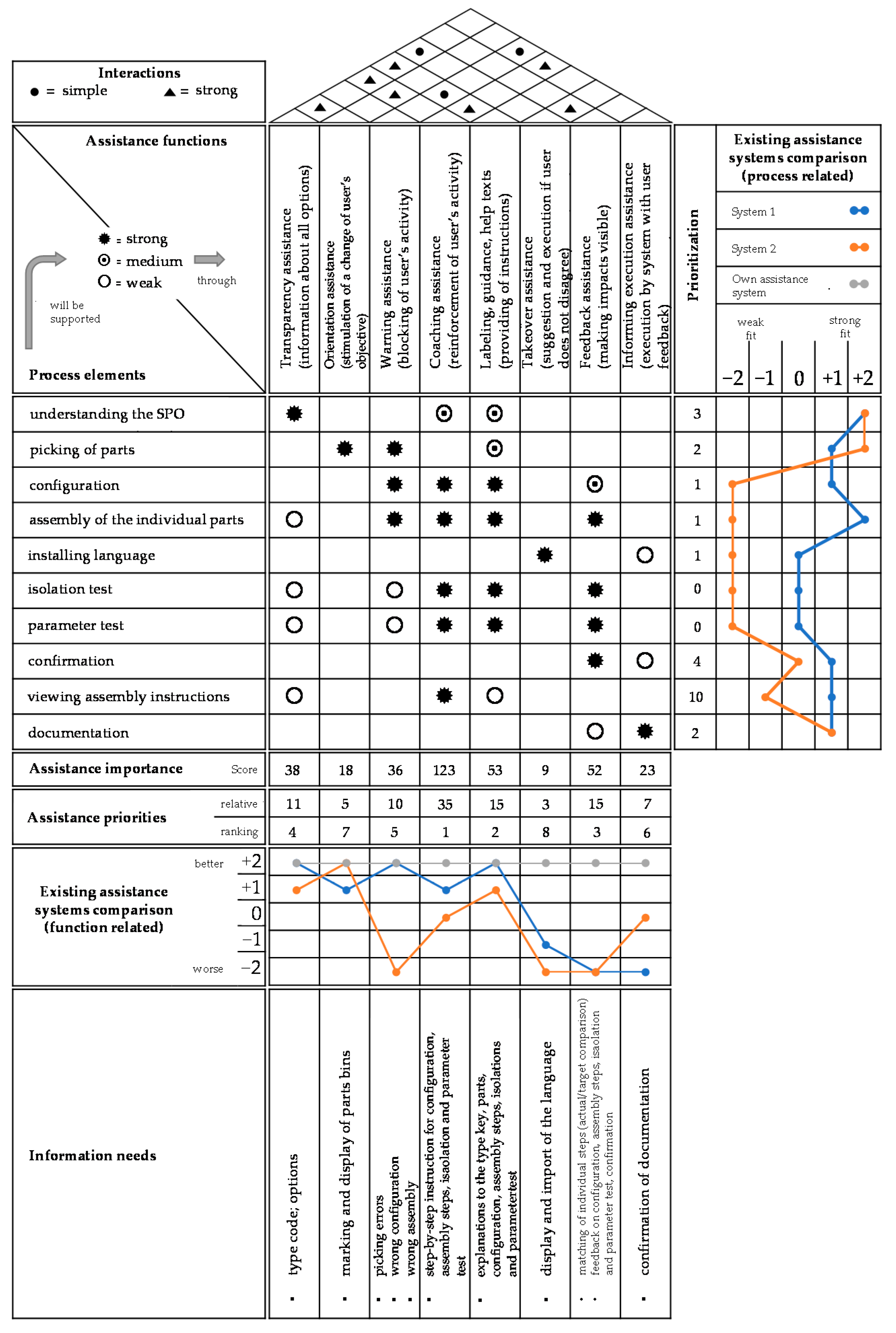
5.3.3. Phase 3: Cognitive Assistance System Concept

In the third phase, the rough design of the assistance concept was performed according to the procedure in Section 4.3.2. For this purpose, the findings from the first HoQ were adopted in the first section and the applications of possible assistance systems were analyzed. Then, in a second section, assistance functions were collected, linked, evaluated and then consolidated into an assistance construct.
First, the process elements and their priorities were transferred. Based on this, suitable assistance systems were identified from the market and were evaluated in terms of which of the process elements might be effectively supported by these systems. An assembly assistance system (visualization of assembly instructions) with integrated image-based assembly inspection as well as a pick-by-light system (lighting up of bins for the relevant assembly step in order to indicate the picking position of parts) were selected. The selected assembly assistance system could be identified as well-suited, especially for the assembly steps. The pick-by-light system suits well for the picking tasks (correct parts and quantity).
In the second step, suitable assistance functions were selected by the project team for each process element as an optimization action to improve the assembly process. Multiple assistance functions may be required to support several process elements. In this way, a set of assistance functions was created, which was examined by the project team in the correlation matrix for further correlations. For this purpose, the determined assistance functions are analyzed individually in relation to the process elements. In this way, further correlations can be determined, whereby each assistance function can also have an influence on other process elements. After that, the interactions of the assistance functions to each other were determined in the roof (Figure 15).
Performing these steps, the defined assistance functions were analyzed for their functionality in relation to typical assistance systems and their functionalities. The comparison highlighted the effect of the range of functions of the assistance systems available on the market and whether it makes sense to develop its own system. By combining all components and analyzing the links between requirements and processes, the project team was able to determine what assistance functions the system to be developed should consist of, as shown in Figure 15. The assistance functions “coaching assistance” and “feedback assistance” as well as the assistance by “labeling, guidance, help texts” turned out to be particularly important.
At this point, the research team was capable to generate initial ideas as to what a concrete assistance system could look like.

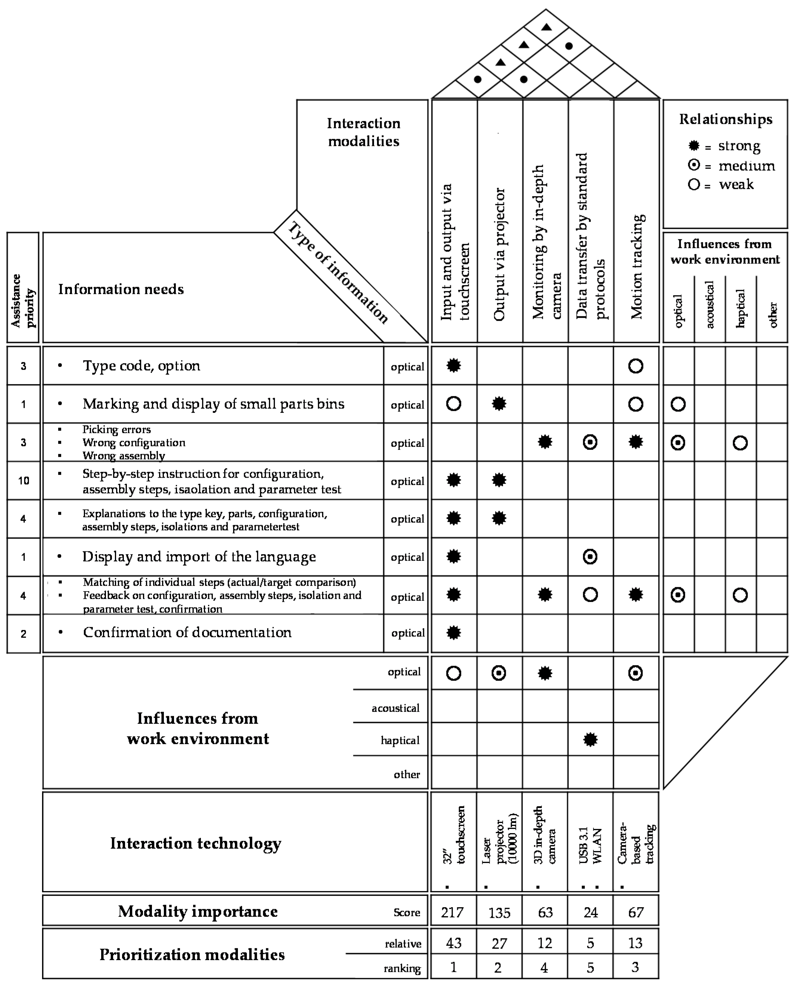
5.3.4. Phase 4: Detail Design

The fourth phase consists of the detailed design of the rough assistance construct. In the first section, the findings from the previous section are transferred and analyzed in the working environment. This was followed in the second section by the application of the developed logic for the development of interfaces. Finally, in a third section, the selected interaction modalities were linked and evaluated.
In the first section of this step, the assistance functions and their priorities and the associated information needs were transferred. Then, the planning team categorized the information needs according to their information type. These were mainly classified as visual. The information needs were then analyzed together with the relevant assistance functions for influences from the work environment.
In the second section, suitable interaction modalities were selected for individual assistance functions based on their information needs. This was completed using the concept developed for the design of interfaces and multimodal interaction. In this context, touchscreen was mainly selected as a suitable input and output modality by workers and engineers. A laser projector could be used as a further output modality. Data acquisition, on the other hand, should be ensured by means of depth cameras, connection standards and eye trackers.
The interaction modalities were evaluated for influences from the working environment. Visual and haptic influences are the main factors affecting the functionality of the interaction modalities. Based on these findings, the project team was able to define the features of the interaction modalities.
In the third section, the interactions between interaction modalities and assistance functions were correlated and evaluated together with their information needs. Thereby, the interaction modalities can also generate advantages for other functions. By combining all the components and evaluating the interactions between assistance functions and interaction modalities, the project team was able to fine-tune the assistance system (Figure 16 for results).

5.3.5. Cognitive Assistance System Planning Summary

Based on the results of our case study evaluation, the identified design steps directed us to the following findings, use cases and recommendations for the design and configuration of the cognitive assistance system:
  • The assistance system is computer-based;
  • Workers need to log into the assistance system;
  • The orders are displayed to the worker via the touchscreen combined with the defined shipment date (priority ranking);
  • The type code is processed by the system and the essential information is made available to the worker in an automated and interpreted format;
  • The picking of the parts is supported by a laser projection, which lights up the required boxes for small parts;
  • The correct picking (right part in the right quantity) is monitored by a camera. In case of a wrong pick, a visual warning is displayed;
  • The configuration is completed according to visual instructions (pictures) via the touch screen and by verification of the settings by the system. For this purpose, the board is connected to the system via USB. If necessary, a visual warning is displayed in the event of incorrect configuration;
  • The individual parts are assembled according to visual instructions via the touchscreen and by monitoring the assembly on the system side. For this purpose, the assembly steps are monitored, recorded with a depth camera and the assembly result is compared with a reference/actual comparison. If necessary, a visual warning is displayed in the event of incorrect assembly;
  • Detail level of instructions could be based on the experience level of the workers;
  • Changes of assembly procedures are displayed and must be confirmed by the worker;
  • The isolation and parameter tests are performed according to visual instructions via the touchscreen. If necessary, a visual warning is displayed in the event of non-conformance with target values;
  • Confirmation and documentation are performed automatically by the system with the camera via a reference/actual comparison. The user receives visual confirmation of each step via the touchscreen.

5.3.6. Phase 5: Prototype Realization and Testing

Based on the design steps, a prototype was developed and tested in relation to production use cases. The following features were implemented: login to the workstation by ID-card, adjustment of work instruction based on experience level (beginner and expert), order overview, scanning of the order (barcode) and automatic start of the photo-based work instruction, automatic push notifications for changes and special instructions, possibility to access additional information, such as drawings and videos, picking assistance with information about the number and type of parts to be picked by electronic ink-based displays, which are confirmed by a button after the picking step.
The control of the pick-by-display system runs directly through the assistance system, transparency of current cycle times for each assembly step for the worker, integrated isolation and parameter test, automatic documentation of the assembly steps and measurement results. Automatic recognition of the assembly progress was not used in the prototype; the workers could continue the assembly steps via the touchscreen monitor. The control and monitoring of the picks and assembly results in the prototype were not implemented since a camera implementation would have exceeded the cost limits. The finalized prototype is illustrated in Figure 17.
The realized assembly workstation prototype was tested interdisciplinarily with specialists from production, IT-engineers and a voluntary set of five workers. The workers assembled a typical job and then provided feedback on the following topics: general impression and scope of functions, quality of information provision and assistance functions, type of the information presentation and interaction, range and intensity of functions. Standardized test methods in the field of usability or user experience were not used due to the effort involved in the prototype phase. The productivity indicators were also only included for qualitative argumentation. Table 5 explains an excerpt of the evaluation results.
Few controversial discussions during the evaluation of the prototype arise, presented as follows. The worker is identified in the prototype by an ID card. This allows the assembly steps to be documented automatically without the need for manual documentation/signature. Furthermore, through the login, the assembly instructions can be adjusted to expert or beginner level. This was valuable from the point of view of the workers as well. However, performance data can be logged at the same time, which was seen as negative for the workers. The main concern here was the risk of monitoring and resulting negative consequences. In addition to visualizing the assembly instructions, the assistance system also visualizes the time required for the individual steps in terms of target and actual cycle times. This should provide orientation, but the workers rated this visualization rather negatively. The continuous display of cycle times created pressure and mental harassment.

6. Discussion and Limitations

6.1. Discussion

The research challenge is, on the one hand, the fact that the design of cognitive assistance systems is a complex task due to the multitude of technologies and the possibility of different levels of assistance. On the other hand, both the company’s requirements for the work process and the workers’ requirements must be considered and correlated with the technological possibilities and assistance levels. The goal for the design of an assistance system is the benefit for the optimization of a work process and the acceptance of the workers to use it. Therefore, the goal of this research was to develop a method to enable systematically design cognitive assistance systems that integrate both company and worker requirements in a participatory way.
The research was approached by design science research. For this purpose, the existing QFD approach was adapted and expanded to the six-phase CAS-QFD.
It is assumed that it is possible using the CAS-QFD for designing cognitive assistance systems (operationality), as the industry example shows. Furthermore, the six-phase method shows how the design is performed (research question 1) and which adaptations of a common QFD method were necessary (research question 2). The method also describes how the design of assistance systems is structured, starting from the assembly process as a preliminary step (research question 3), and how the worker and company requirements are addressed (research question 4) to reach step-by-step the final design of a cognitive assistance system. The evaluation shows that the identified requirements could be fulfilled to a large extent by using CAS-QFD based on the results of the prototype evaluation. The solution hypotheses were confirmed.
From the industrial application, we expect that the method will provide the user with a transparent overview of the design steps in each phase. At the same time, alternatives can always be planned and compared with each other to determine their effects. In later phases, it became clear that the context analysis regarding the process and the work system was essential for the later design. Many of ideas and recommendations were based on observed and collaboratively documented influences in the work environment. The participation of the workers, engineers and managers, although time-consuming, was positive in terms of the quality of the requirements and solution strategies. This has already been demonstrated in other areas regarding QFD [115,116].
Based on the evaluation discussions with the project team, it is assumed that the step-by-step design could reduce complexity (ease of use). This is the advantage of the sequential process of the QFD method, which has already been recognized in other approaches [104,105,106,107,108]. The research team was able to focus on the essential steps at each phase so that they remained manageable. The ability to proceed in iterations, repeating steps backwards and forwards, including changes, resulted in a robust design with traceable chains of reasoning (efficiency). This is also confirmed by other QFD studies in other fields [117,118].
The strict separation of requirements and assistance functions as well as technical features prevented the project team from discussing technologies and realizations too early and, therefore, losing focus on the requirements and the optimization of the assembly process.
The definition of generic assistance functions (Table 1) proved to be a suitable tool during the evaluation. The defined levels were able to integrate and summarize the content of the assistance, the intensity of the assistance and the automation level to a good extent. Thus, the adaptability of the assistance system could also be discussed and planned based on the following questions; for example: can the system assist differently depending on the complexity of the task and the experience level of the worker? Can the levels be adjusted by the worker himself or are they predefined?
The market comparison included in the second phase was rated as helpful since it already became clear and can be discussed transparently whether a company should develop its own assistance system or buy or adapt an available one.
The evaluation case study showed that it is challenging to find the right level of abstraction for a complex and long assembly process to consider the most important steps on the one hand and not to overload the method on the other hand. Regarding the worker and company requirements, we found that, in the case of a cognitive assistance system, these can be contradictory to each other. For example, the company has the requirement to increase process control and, at the same time, the worker in the process neither wants to be monitored nor more strongly controlled within the work tasks. The method does not provide a system for resolving such conflicts of requirements.

6.2. Limitations

The limitations of our research are that CAS-QFD was only applied to one industrial assembly process. The generalization capability of the method is, therefore, limited and should be repeatedly tested in future case studies.
Furthermore, the method does not provide any logic for evaluating the result or for comparing it to the status quo or to the variants among themselves.
CAS-QFD has the same disadvantages as the known QFD methods, such as: the method offers a systematic design of a complex system, but, simultaneously, the time requirement is also high for the team. Furthermore, it is a subjective method so that estimations of correlations, interactions, etc., are based on the knowledge, experience and consensus views of the team members. The larger the matrices of requirements become, the higher the complexity becomes for the project team to correlate them [97,119,120,121,122,123].

6.3. Theoretical Implications

The theoretical contribution of our research is in the methodological approach to designing cognitive assistance systems for assisting and supporting the realization of assembly processes. We can summarize five aspects as a contribution to the theory. We could demonstrate that (1) it is possible to design a socio-technical system such as a cognitive assistance system on the basis of QFD, that (2) this approach extends existing QFD approaches as a new field of application, that (3) it is a new contribution to human-centred design [49,50,51,52] and for participatory planning [123,124,125,126,127] of assistance systems, that (4) with the presented approach, the core goals of Industry 5.0 for a stronger consideration of humans in production, a contribution is achieved and with that (5) an example for the integration of company and worker requirements is presented on the basis of a case study.

6.4. Managerial Implications

In practice, the method enables the pragmatic design of cognitive assistance systems to improve assembly processes in terms of productivity, quality and worker satisfaction. The method enables that only the assembly process steps are intended for an assistance where it is worthwhile to optimize. Nevertheless, the combination, i.e., the linkage of several assistance functions, can be included, whereby comprehensive assistance potentials can also be identified. The method also enables the interdisciplinary team to consider different perspectives and integrate them into the design. The method can be easily extended in the case of technology changes and developments.
Due to the high level of user participation in the development process, it is assumed that user acceptance will increase. The users of the future developed assistance system are considered at all stages of the methodology and their subjective opinion is included in the development and/or selection of assistance functions and interaction modalities.
In relation to existing planning approaches, the advantage of the method lies not only in the ability to select or derive concrete design attributes of an assistance system but also to recognize and reconsider their effects after selection or derivation and to reconsider them.

6.5. Conclusions and Outlook

Based on the results and their analysis, the research team identified four directions for further research, as follows:
(1) To increase the generalizability of the method, there should be more replications of case studies. For this purpose, examples with different assembly configurations, employees, quantities, complexities and products should be applied.
(2) To enable evaluability, quantitative methods, such as the analytical hierarchy process, should be integrated, as has already been completed in some QFD applications [128,129,130], to be able to evaluate multiple criteria from the perspective of worker benefits as well as company benefits. The economic evaluation of such systems should also be integrated as this is one of the most important decision-making criteria [48] on the part of companies.
(3) The elicitation of worker requirements and the process analysis with the known methods (interviews, focus groups, etc.) is difficult because it is not clear how to systematically identify the requirements of the workers in a representative way. Therefore, approaches such as those in Refs. [131,132] should be combined with CAS-QFD to support project teams even more systematically in the analysis and requirements gathering. This is the case because, in the end, it is crucial to know a great deal about the work environment of the assistance system and to develop a detailed understanding of worker requirements, their problems, ways of thinking and wishes, as already [10,17,133] mentioned in their work. This would also allow the design results to be fed back into the process modelling at the end of the sixth phase to see how the assistance system supports the corresponding assembly process step.
(4) Further research should be conducted in production information systems as another factor to be considered for the design of cognitive assistance systems is what would be another decision dimension within the design process. Cognitive assistance systems are not operated in a stand-alone system but are integrated into existing, usually heterogeneous, IT-infrastructures and are connected to enterprise resource planning systems, manufacturing execution systems and other systems via a network environment. In this way, for example, context recognition for the assistance system is realized through order data and the work plans and logistics data from other systems [134,135]. The assistance content has to be automatically imported into the assistance system either by other systems, such as computer-aided design systems, computer-aided manufacturing systems, product lifecycle management systems or product data management systems [136,137], or the content needs to be generated manually.

Author Contributions

Conceptualization, B.P., D.P. and C.C.; methodology, B.P.; validation, B.P.; resources, B.P.; writing—original draft preparation, B.P.; writing—review and editing, B.P. and C.C.; visualization, B.P.; supervision, C.C. and D.P. All authors have read and agreed to the published version of the manuscript.

Funding

This research received no external funding.

Institutional Review Board Statement

Not applicable.

Informed Consent Statement

Not applicable.

Data Availability Statement

Data available on request from the authors.

Conflicts of Interest

The authors declare no conflict of interest.

References

  1. Kagermann, H. Recommendations for Implementing the Strategic Initiative INDUSTRIE 4.0: Securing the Future of German Manufacturing Industry; Final Report of the Industrie 4.0 Working Group; Forschungsunion: Berlin, Germany, 2013. [Google Scholar]
  2. Kagermann, H. Change through Digitization—Value Creation in the Age of Industry 4.0. In Management of Permanent Change; Springer: Berlin/Heidelberg, Germany, 2015. [Google Scholar]
  3. Ansari, F.; Seidenberg, U. A Portfolio for Optimal Collaboration of Human and Cyber Physical Production Systems in Problem-Solving. In Proceedings of the 13th International Association for Development of the Information Society (IADIS) International Conference on Cognition and Exploratory Learning in the Digital Age (CELDA), Mannheim, Germany, 28–30 October 2016. [Google Scholar]
  4. Birkel, H.S.; Veile, J.W.; Müller, J.M.; Hartmann, E.; Voigt, K.-I. Development of a Risk Framework for Industry 4.0 in the Context of Sustainability for Established Manufacturers. Sustainability 2019, 11, 384. [Google Scholar] [CrossRef] [Green Version]
  5. Oztemel, E.; Gursev, S. Literature review of Industry 4.0 and related technologies. J. Intell. Manuf. 2020, 31, 127–182. [Google Scholar] [CrossRef]
  6. Wagner, T.A.; Herrmann, C.; Thiede, S. Industry 4.0 Impacts on Lean Production Systems. Procedia CIRP 2017, 63, 125–131. [Google Scholar] [CrossRef]
  7. Lu, Y. Industry 4.0: A survey on technologies, applications and open research issues. J. Ind. Inf. Integr. 2017, 6, 1–10. [Google Scholar] [CrossRef]
  8. Vuksanović Herceg, I.; Kuč, V.; Mijušković, V.M.; Herceg, T. Challenges and Driving Forces for Industry 4.0 Implementation. Sustainability 2020, 12, 4208. [Google Scholar] [CrossRef]
  9. Munir, S.; Stankovic, J.A.; Liang, C.J.M.; Lin, S. Cyber Physical System Challenges for Human-in-the-Loop Control. In Proceedings of the Presented as part of the 8th International Workshop on Feedback Computing, USENIX, San Jose, CA, USA, 24–28 June 2013; Volume 4, pp. 1–4. [Google Scholar]
  10. Siemieniuch, C.E.; Sinclair, M.A.; Henshaw, M.J.C. Global drivers, sustainable manufacturing and systems ergonomics. Appl. Ergon. 2015, 51, 104–119. [Google Scholar] [CrossRef] [Green Version]
  11. Bänziger, T.; Kunz, A.; Wegener, K. Optimizing Human–Robot Task Allocation Using a Simulation Tool Based on Standardized Work Descriptions. J. Intell. Manuf. 2020, 31, 1635–1648. [Google Scholar] [CrossRef]
  12. Romero, D. Towards an Operator 4.0 Typology: A Human-Centric Perspective on the Fourth Industrial Revolution Technologies. In Proceedings of the CIE46, Tianjin, China, 29–31 October 2016. [Google Scholar]
  13. Kaasinen, E.; Schmalfuß, F.; Özturk, C.; Aromaa, S.; Boubekeur, M.; Heilala, J.; Heikkilä, P.; Kuula, T.; Liinasuo, M.; Mach, S.; et al. Empowering and engaging industrial workers with Operator 4.0 solutions. Comput. Ind. Eng. 2020, 139, 105678. [Google Scholar] [CrossRef]
  14. Nahavandi, S. Industry 5.0—A Human-Centric Solution. Sustainability 2019, 11, 4371. [Google Scholar] [CrossRef] [Green Version]
  15. Neumann, W.P.; Winkelhaus, S.; Grosse, E.H.; Glock, C.H. Industry 4.0 and the human factor—A systems framework and analysis methodology for successful development. Int. J. Prod. Econ. 2021, 233, 107992. [Google Scholar] [CrossRef]
  16. Breque, M.; De Nul, L.; Petridis, A. Industry 5.0. Towards a Sustainable, Human-Centric and Resilient European Industry. Available online: https://op.europa.eu/en/publication-detail/-/publication/468a892a-5097-11eb-b59f-01aa75ed71a1/ (accessed on 15 January 2022).
  17. Reiman, A.; Kaivo-oja, J.; Parviainen, E.; Takala, E.P.; Lauraeus, T. Human factors and ergonomics in manufacturing in the industry 4.0 context—A scoping review. Technol. Soc. 2021, 65, 101572. [Google Scholar] [CrossRef]
  18. Fiasche, M.; Pinzone, M.; Fantini, P.; Alexandru, A.; Taisch, M. Human-Centric Factories 4.0: A Mathematical Model for Job Allocation. In Proceedings of the 2016 IEEE 2nd International Forum on Research and Technologies for Society and Industry Leveraging a Better Tomorrow, Bologna, Italy, 7–9 September 2016. [Google Scholar] [CrossRef]
  19. Peruzzini, M.; Pellicciari, M. A framework to design a human-centred adaptive manufacturing system for aging workers. Adv. Eng. Inform. 2017, 33, 330–349. [Google Scholar] [CrossRef]
  20. Hunter, S.L. Ergonomic evaluation of manufacturing system designs. J. Manufact. Syst. 2002, 20, 429–444. [Google Scholar] [CrossRef]
  21. Bidanda, B.; Ariyawongrat, P.; Needy, K.L.; Norman, B.A.; Tharmmaphornphilas, W. Human related issues in manufacturing cell design, implementation, and operation: A review and survey. Comput. Ind. Eng. 2005, 48, 507–523. [Google Scholar] [CrossRef]
  22. Syberfeldt, A.; Holm, M.; Danielsson, O.; Wang, L.; Brewster, R.L. Support systems on the industrial shop-floors of the future—Operators’ perspective on augmented reality. Procedia CIRP 2016, 44, 108–113. [Google Scholar] [CrossRef]
  23. Almagrabi, H.; Malibari, A.; McNaught, J. A Survey of Quality Prediction of Product Reviews. Int. J. Adv. Comput. Sci. Appl. 2015, 10, 49–58. [Google Scholar] [CrossRef] [Green Version]
  24. Peruzzini, M.; Grandi, F.; Pellicciari, M. Exploring the potential of Operator 4.0 interface and monitoring. Comput. Ind. Eng. 2020, 139, 105600. [Google Scholar] [CrossRef]
  25. Fantini, P.; Pinzone, M.; Taisch, M. Placing the operator at the centre of Industry 4.0 design: Modelling and assessing human activities within cyber-physical systems. Comput. Ind. Eng. 2018, 139, 105058. [Google Scholar] [CrossRef]
  26. Frigo, M.A.; da Silva, E.C.C.; Barbosa, G.F. Augmented Reality in Aerospace Manufacturing: A Review. J. Ind. Intell. Inf. 2016, 4, 125–130. [Google Scholar] [CrossRef]
  27. Makris, S.; Karagiannis, P.; Koukas, S.; Matthaiakis, A.S. Augmented reality system for operator support in human–robot collaborative assembly. CIRP Ann. 2016, 4, 61–64. [Google Scholar] [CrossRef]
  28. Nee, A.Y.; Ong, S.K. Virtual and augmented reality applications in manufacturing. IFAC Proc. Vol. 2013, 46, 15–26. [Google Scholar] [CrossRef] [Green Version]
  29. Matyi, H.; Veres, P.; Bányai, T.; Demin, V.; Tamás, P. Digitalization in Industry 4.0: The Role of Mobile Devices. J. Prod. Eng. 2020, 23, 75–78. [Google Scholar] [CrossRef]
  30. Kong, X.T.R.; Luo, H.; Huang, G.Q.; Yang, X. Industrial wearable system: The human-centric empowering technology in Industry 4.0. J. Intell. Manuf. 2018, 17, 1–17. [Google Scholar] [CrossRef]
  31. Chan, M.; Estève, D.; Fourniols, J.Y.; Escriba, C.; Campo, E. Smart wearable systems: Current status and future challenges. Artif. Intell. Med. 2012, 20, 137–156. [Google Scholar] [CrossRef]
  32. Hao, Y.; Helo, P. The role of wearable devices in meeting the needs of cloud manufacturing: A case study. Robot. Comput. Integr. Manuf. 2017, 45, 168–179. [Google Scholar] [CrossRef]
  33. Zhou, J.; Lee, I.; Thomas, B.; Menassa, R.; Farrant, A.; Sansome, A. In-situ support for automotive manufacturing using spatial augmented reality. Int. J. Virtual Real. 2012, 11, 33–41. [Google Scholar] [CrossRef] [Green Version]
  34. Simonetto, M.; Peron, M.; Fragapane, G.; Sgarbossa, F. Digital Assembly Assistance System in Industry 4.0 Era: A Case Study with Projected Augmented Reality. In Advanced Manufacturing and Automation X; IWAMA. Lecture Notes in Electrical Engineering; Wang, Y., Martinsen, K., Yu, T., Wang, K., Eds.; Springer: Singapore, 2020; Volume 737. [Google Scholar] [CrossRef]
  35. Mark, B.; Rauch, E.; Matt, D. Study of the impact of projection-based assistance systems for improving the learning curve in assembly processes. Procedia CIRP 2020, 88, 98–103. [Google Scholar] [CrossRef]
  36. Sorostinean, R.; Gellert, A.; Pirvu, B.-C. Assembly Assistance System with Decision Trees and Ensemble Learning. Sensors 2021, 21, 3580. [Google Scholar] [CrossRef]
  37. Gellert, A.; Sorostinean, R.; Pirvu, B.-C. Robust Assembly Assistance Using Informed Tree Search with Markov Chains. Sensors 2022, 22, 495. [Google Scholar] [CrossRef]
  38. Precup, S.-A.; Gellert, A.; Matei, A.; Gita, M.; Zamfirescu, C.-B. Towards an Assembly Support System with Dynamic Bayesian Network. Appl. Sci. 2022, 12, 985. [Google Scholar] [CrossRef]
  39. Ruppert, T.; Jaskó, S.; Holczinger, T.; Abonyi, J. Enabling Technologies for Operator 4.0: A Survey. Appl. Sci. 2018, 8, 1650. [Google Scholar] [CrossRef] [Green Version]
  40. Aljinović, A.; Gjeldum, N.; Bilić, B.; Mladineo, M. Optimization of Industry 4.0 Implementation Selection Process towards Enhance-ment of a Manual Assembly Line. Energies 2022, 15, 30. [Google Scholar] [CrossRef]
  41. Chu, C.-H.; Liao, C.-J.; Lin, S.-C. Comparing Augmented Reality-Assisted Assembly Functions—A Case Study on Dougong Structure. Appl. Sci. 2020, 10, 3383. [Google Scholar] [CrossRef]
  42. Kolla, S.; Sanchez, A.; Plapper, P. Comparing Effectiveness of Paper Based and Augmented Reality Instructions for Manual Assembly and Training Tasks. In Proceedings of the Conference on Learning Factories (CLF), Graz, Austria, 1–2 July 2021. [Google Scholar]
  43. Vernim, S.; Reinhart, G. Usage Frequency and User-Friendliness of Mobile Devices in Assembly. Procedia CIRP 2016, 57, 510–515. [Google Scholar] [CrossRef]
  44. Funk, M.; Kosch, T.; Greenwald, S.; Schmidt, A. A benchmark for interactive augmented reality instructions for assembly tasks. In Proceedings of the 14th International Conference on Mobile and Ubiquitous Multimedia (MUM’15). Association for Computing Machinery, New York, NY, USA, 30 November–2 December 2015; pp. 253–257. [Google Scholar] [CrossRef]
  45. Fletcher, S.R.; Johnson, T.L.; Adlon, T. Adaptive automation assembly: Identifying system requirements for technical efficiency and worker satisfaction. Comput. Ind. Eng. 2020, 139, 105772. [Google Scholar] [CrossRef]
  46. Pimminger, S.; Kurschl, W.; Panholzer, L.; Schönböck, J. Exploring the Learnability of Assembly Tasks Using Digital Work Instructions in a Smart Factory. Procedia CIRP 2021, 104, 696–701. [Google Scholar] [CrossRef]
  47. Jenderny, S.; Foullois, M.; Kato-Beiderwieden, A.-L.; Bansmann, M.; Wöste, L.; Lamß, J.; Maier, G.W.; Röcker, C. Development of an instrument for the assessment of scenarios of work 4.0 based on socio-technical criteria. In Proceedings of the 11th PErvasive Technologies Related to Assistive Environments Conference on–PETRA’18, Corfu, Greece, 26–29 June 2018; ACM Press: New York, NY, USA, 2018; pp. 319–326. [Google Scholar]
  48. Bauer, W.; Klapper, J. A development scenario of the work area “intralogistics” under the influence of industry 4.0 technologies and its evaluation on the basis of a Delphi study. In Proceedings of the 20th Congress of the International Ergonomics Association (IEA 2018), Florence, Italy, 26–30 August 2018; Springer: Cham, Switzerland, 2019; Volume 825, pp. 812–821. [Google Scholar] [CrossRef]
  49. Werrlich, S.; Nitsche, K.; Notni, G. Demand Analysis for an Augmented Reality based Assembly Training. In Proceedings of the 10th International Conference on Pervasive Technologies Related to Assistive Environments (PETRA’17). Association for Computing Machinery, New York, NY, USA, 21–23 June 2017; pp. 416–422. [Google Scholar] [CrossRef]
  50. Hermawati, S.; Lawson, G. User-centred design of virtual training for automotive industries. In Proceedings of the International Conference on Ergonomics & Human Factors 2013, Cambridge, UK, 15–18 April 2013; pp. 267–274. [Google Scholar]
  51. Stockinger, C.; Stuke, F.; Subtil, I. User-centered development of a worker guidance system for a flexible production line. Hum. Factors Ergon. Manuf. Serv. Ind. 2021, 31, 532–545. [Google Scholar] [CrossRef]
  52. Müller, R.; Kessler, F.; Humphrey, D.W.; Rahm, J. Data in Context: How Digital Transformation Can Support Human Reasoning in Cyber-Physical Production Systems. Future Internet 2021, 13, 156. [Google Scholar] [CrossRef]
  53. Chatti, S.; Laperrière, L.; Reinhart, G.; Tolio, T. CIRP Encyclopedia of Production Engineering; Springer: Berlin/Heidelberg, Germany, 2019; ISBN 978-3-642-35950-7. [Google Scholar]
  54. Lotter, B.; Wiendahl, H.-P. Changeable and Reconfigurable Assembly Systems. In Changeable and Reconfigurable Manufacturing Systems; El Maraghy, H.A., Ed.; Springer: London, UK, 2009; pp. 127–142. [Google Scholar]
  55. Heilala, J.; Voho, P. Modular reconfigurable flexible final assembly system. Assem. Autom. 2001, 21, 20–30. [Google Scholar] [CrossRef]
  56. Gorlach, I.; Wessel, O. Optimal Level of Automation in the Automotive Industry. Eng. Lett. 2008, 16, 141–149. [Google Scholar]
  57. Yoshimura, M.; Yoshida, S.; KonishI, K.; Izui, S.; Nishiwaki, Y.; Inamori, A.; Nomura, K.; Mitsuyuki, Y.; Kawaguchi, Y.; Inagaki, T. A rapid analysis method for production line design. Int. J. Product. Res. 2006, 44, 1171–1192. [Google Scholar] [CrossRef]
  58. Swift, K.G.; Booker, J.D. Chapter 10—Assembly Systems. In Manufacturing Process Selection Handbook; Swift, K.G., Booker, J.D., Eds.; Butterworth-Heinemann: Oxford, UK, 2013; pp. 281–289. [Google Scholar]
  59. Schleich, H.; Schaffer, L.; Scavarda, F. Managing complexity in automotive production. In Proceedings of the 19th international Conference on Production Research, Valparaiso, Chile, 29 July–2 August 2007. [Google Scholar]
  60. Matondang, M.Z.; Jambak, M.I. Soft computing in optimizing assembly lines balancing. J. Comput. Sci. 2010, 6, 141–162. [Google Scholar] [CrossRef] [Green Version]
  61. Urbanic, R.J.; El Maraghy, H.A. Modeling of Manufacturing Process Complexity. In Springer Series in Advanced Manufacturing; Springer: London, UK, 2006; pp. 425–436. [Google Scholar] [CrossRef]
  62. Doerr, K.H.; Arreola-Risa, A. A worker-based approach for modeling variability in task completion times. IIE Trans. 2007, 32, 625–636. [Google Scholar] [CrossRef]
  63. Gullander, P.; Davidsson, A.; Dencker, K.; Fasth, Å.; Fässberg, T.; Harlin, U.; Stahre, J. Towards a production complexity model that supports operation, re-balancing and man-hour planning. In Proceedings of the 4th Swedish Production Symposium (SPS), Lund, Sweden, 3–5 May 2011. [Google Scholar]
  64. Fast-Berglund, Å.; Fässberg, T.; Hellman, F.; Davidsson, A.; Stahre, J. Relations between complexity, quality and cognitive automation in mixed-model assembly. J. Manuf. Syst. 2013, 32, 449–455. [Google Scholar] [CrossRef] [Green Version]
  65. Bol, L.; Hacker, D.J.; Mattarella-Micke, A.; Beilock, S.L.; Seel, N.M.; Rosenstand, C.A.F.; Ell, S. Cognitive Tasks and Learning. Encyclopedia of the Sciences of Learning; Springer Science & Business Media: Boston, MA, USA, 2012; pp. 619–622. [Google Scholar] [CrossRef]
  66. Rasmussen, J.; Pejtersen, A.M.; Schmidt, K. Taxonomy for Cognitive Work Analysis; Grafisk Service: Roskilde, Denmark, 1990. [Google Scholar]
  67. Kahneman, D. A perspective on judgment and choice: Mapping bounded rationality. Am. Psychol. 2003, 58, 697–720. [Google Scholar] [CrossRef] [Green Version]
  68. Endsley, M.R. Toward a theory of situation awareness in dynamic systems. Hum. Factors J. 1995, 37, 32–64. [Google Scholar] [CrossRef]
  69. Wickens, C.D.; Hollands, J.G. Engineering Psychology and Human Performance, 5th ed.; Prentice-Hall Inc.: Upper Saddle River, NJ, USA, 2000. [Google Scholar]
  70. Yang, X.; Plewe, D.A. Assistance Systems in Manufacturing: A Systematic Review. In Advances in Ergonomics of Manufacturing: Managing the Enterprise of the Future, Proceedings of the AHFE 2016 International Conference on Human Aspects of Advanced Manufacturing, Orlando, FL, USA, 27–31 July 2016; Schlick, C., Trzcielinski, S., Eds.; Springer International Publishing: Cham, Switzerland, 2016; pp. 279–289. [Google Scholar]
  71. Li, D.; Fast-Berglund, Å.; Salunkhe, O.; Fast-Berglund, Å.; Skoogh, A.; Broberg, J. Effects of Information Content in Work Instructions for Operator Performance. Procedia Manuf. 2018, 25, 628–635. [Google Scholar] [CrossRef]
  72. Longo, F.; Nicoletti, L.; Padovano, A. Smart operators in industry 4.0: A human-centered approach to enhance operators’ capabilities and competencies within the new smart factory context. Comput. Ind. Eng. 2017, 113, 144–159. [Google Scholar] [CrossRef]
  73. Bellgran, M.; Säfsten, K. Production Development—Design and Operation of Production Systems, 1st ed.; Springer: London, UK, 2010. [Google Scholar]
  74. Lusic, M.; Fischer, C.; Bonig, J.; Hornfeck, R.; Franke, J. Worker information systems: State of the art and guideline for selection under consideration of company specific boundary conditions. Procedia CIRP 2016, 44, 1113–1118. [Google Scholar] [CrossRef] [Green Version]
  75. Rainer, R.K.; Cegielski, C.G. Introduction to Information Systems; John Wiley & Sons: Hoboken, NJ, USA, 2011. [Google Scholar]
  76. Teubner, S.; Rimpau, C.; Reinhart, G. Approaching Dynamic and Individual Worker Information Systems. Procedia CIRP 2020, 93, 795–801. [Google Scholar] [CrossRef]
  77. Stair, R.M.; Reynolds, G.W. Fundamentals of Information Systems. A Managerial Approach; Thomson Course Technology: Boston, MA, USA, 2010. [Google Scholar]
  78. Hinrichsen, S.; Bornewasser, M. How to Design Assembly Assistance Systems. In Intelligent Human Systems Integration 2019; Springer: San Diego, CA, USA, 2019; pp. 286–292. [Google Scholar] [CrossRef]
  79. Schlick, C.; Ziefle, M.; Park, M.; Luczak, H. Visual Displays. In The Human-Computer Interaction Handbook: Fundamentals, Evolving Technologies, and Emerging Applications, 2nd ed.; Sears, A., Jacko, J.A., Eds.; Lawrence Erlbaum Associates: New York, NY, USA, 2008; pp. 201–229. [Google Scholar]
  80. Schmidt, A.; Gellersen, H.; Beigl, M.; Thate, O. Developing user interfaces for wearable computers: Don’t stop to point and click. In International Workshop on Interactive Applications of Mobile Computing (IMC2000); University of Karlsruhe: Karlsruhe, Germany, 2000. [Google Scholar]
  81. Mourtzis, D.; Zogopoulos, V. Augmented reality application to support the assembly of highly customized products and to adapt to production re-scheduling. Int. J. Adv. Manuf. Technol. 2019, 105, 1–12. [Google Scholar] [CrossRef]
  82. Frohm, J.; Lindström, V.; Winroth, M.; Stahre, J. Levels of Automation in Manufacturing. Int. J. Ergon. Hum. Factors 2008, 30, 181–207. Available online: https://core.ac.uk/download/pdf/70575908.pdf (accessed on 12 February 2022).
  83. Akao, Y. Quality Function Deployment: Integration Customer Requirements into Product Design; Mazur, G.H., Ed.; Productivity Press: Cambridge, MA, USA, 1990. [Google Scholar]
  84. Cristiano, J.J.; Liker, J.K.; White, C.C., III. Key factors in the successful application of quality function deployment. IEEE Trans. Eng. Manag. 2001, 48, 81–95. [Google Scholar] [CrossRef]
  85. Sorli, M.; Stokic, D. Innovating in Product/Process Development: Gaining Pace in New Product Development; Springer: London, UK; New York, NY, USA, 2009. [Google Scholar]
  86. Cohen, L. Quality Function Deployment: How to Make QFD Work for You; Addison-Wesley: Boston, MA, USA, 1995. [Google Scholar]
  87. Terninko, J. Step-by-Step QFD: Customer-Driven Product Design, 2nd ed.; Routledge: New York, NY, USA, 1997. [Google Scholar]
  88. Clausing, D.P. Total Quality Development: A Step by Step Guide to World-Class Concurrent Engineering; ASME Press: New York, NY, USA, 1994. [Google Scholar]
  89. Erdil, N.O.; Arani, O.M. Quality function deployment: More than a design tool. Int. J. Qual. Serv. Sci. 2018, 11, 142–166. [Google Scholar] [CrossRef]
  90. Delgado-Hernandez, D.J.; Bampton, K.E.; Aspinwall, E. Quality function deployment in construction. Constr. Manag. Econ. 2007, 25, 597–609. [Google Scholar] [CrossRef]
  91. Raharjo, H.; Brombacher, A.C.; Xie, M. Dealing with Subjectivity in Early Product Design Phase: A Systematic Approach to Exploit Quality Function Deployment Potentials. Comput. Ind. Eng. 2008, 55, 253–278. [Google Scholar] [CrossRef]
  92. Chan, L.K.; Wu, M.-L. Quality function deployment: A literature review. Eur. J. Oper. Res. 2002, 143, 463–497. [Google Scholar] [CrossRef]
  93. Sivasamy, K.; Arumugam, C.; Devadasan, S.R.; Murugesh, R.; Thilak, V.M.M. Advanced models of quality function deployment: A literature review. Qual. Quant. 2016, 50, 1399–1414. [Google Scholar] [CrossRef]
  94. Mochamad, S.; Ismoyo, R.; Agung, F.P.; Sarjana, P.; Manajemen, M.; Mercubana, M.; Selatan, J.M. Employee Expectation Analysis using Quality Function Deployment Method. Int. J. Innov. Sci. Res. Technol. 2018, 3, 228–237. [Google Scholar]
  95. Hernández-Rangel, F.J.; Saavedra-Leos, M.Z.; Morales-Morales, J.; Bautista-Santos, H.; Reyes-Herrera, V.A.; Rodríguez-Lelis, J.M.; Cruz-Alcantar, P. Continuous Improvement Process in the Development of a Low-Cost Rotational Rheometer. Processes 2020, 8, 935. [Google Scholar] [CrossRef]
  96. Crowe, T.J.; Cheng, C. Using quality function deployment in manufacturing strategic planning. Int. J. Oper. Prod. Manag. 1996, 16, 35–48. [Google Scholar] [CrossRef]
  97. Olewnik, A.; Lewis, K. Limitations of the House of Quality to provide quantitative design information. Int. Qual. Reliab. Manag. 2008, 25, 125–146. [Google Scholar] [CrossRef] [Green Version]
  98. Hevner, A.R.; March, S.T.; Park, J.; Ram, S. Design Science in Information Systems Research. Manag. Inf. Syst. Q. 2004, 28, 6. [Google Scholar] [CrossRef] [Green Version]
  99. Peffers, K.; Tuunanen, T.; Rothenberger, M.A.; Chatterjee, S. A Design Science Research Methodology for Information Systems Research. J. Manag. Inf. Syst. 2007, 24, 45–77. [Google Scholar] [CrossRef]
  100. Åkerman, M. Implementing Shop Floor IT for Industry 4.0; Chalmers Tekniska Högskola: Gothenburg, Sweden, 2018. [Google Scholar]
  101. March, S.T.; Smith, G.F. Design and natural science research on information technology. Decis. Support Syst. 1995, 15, 251–266. [Google Scholar] [CrossRef]
  102. Rahman Abdul Rahim, A.; Shariff Nabi Baksh, M. Application of quality function deployment (QFD) method for pultrusion machine design planning. Ind. Manag. Data Syst. 2003, 103, 373–387. [Google Scholar] [CrossRef]
  103. Eringa, K.; Boer, I.L.J. Integrating Quality Function Deployment and Service Blueprinting. In Proceedings of the Tenth Symposium on Quality Function Deployment, Novi, MI, USA, 14–16 June 1998; pp. 289–304. [Google Scholar]
  104. Ekdahl, F.; Gustafsson, A.; Norling, P. QFD for Service Development—A Case Study from Telia Mobitel. In Proceedings of the Third Annual International QFD Symposium, Linköping, Sweden, 1–2 October 1997; pp. 189–207. [Google Scholar]
  105. Kaneko, N. QFD Implementation in Hotel Service. In Proceedings of the Fifth Annual International QFD Symposium, Belo Horizonte, Brazil, 24–25 August 1999; pp. 119–136. [Google Scholar]
  106. Herzwurm, G.; Schockert, S.; Mellis, W. Higher customer satisfaction with prioritizing and focused software quality function deployment. In Proceedings of the Sixth European Conference on Software Quality, Vienna, Austria, 12–16 April 1999. [Google Scholar]
  107. Karlsson, J. Managing software requirements using quality function deployment. Software Qual. J. 1997, 6, 311–326. [Google Scholar] [CrossRef]
  108. Herzwurm, G.; Schockert, S. The leading edge in QFD for software and electronic business. Int. Qual. Reliab. Manag. 2003, 20, 36–55. [Google Scholar] [CrossRef] [Green Version]
  109. Pokorni, B. Human-Centered Design of Digital Assistance Systems in Smart Factories Based on Quality Function Deployment. In Proceedings of the AHFE 2021 Virtual Conference on Human Factors and Systems Interaction, New York, NY, USA, 25–29 July 2021; pp. 155–161. [Google Scholar]
  110. Fasth, Å.; Stahre, J.; Dencker, K. Measuring and analyzing Levels of Automation in an assembly system. In Proceedings of the 41st CIRP International Conference on Manufacturing Systems (ICMS), Tokyo, Japan, 26–28 May 2008. [Google Scholar]
  111. Hinrichsen, S.; Riedieger, D.; Unrau, A. Assistance Systems in Manual Assembly. In Proceedings of the 6th International conference on Production Engineering and Management, Villmer Lemgo, Germany, 29 September 2016; pp. 3–14. [Google Scholar]
  112. Kovacs, K.; Ansari, F.; Geisert, C.; Uhlmann, E.; Glawar, R.; Sihn, W. A Process Model for Enhancing Digital Assistance in Knowledge-Based Maintenance. In Technologien Für Die Intelligente Automation; Springer: Lemgo, Germany, 2018; pp. 87–96. [Google Scholar] [CrossRef] [Green Version]
  113. Keller, T.; Bayer, C.; Bausch, P.; Metternich, J. Benefit evaluation of digital assistance systems for assembly workstations. Procedia CIRP 2016, 81, 441–446. [Google Scholar] [CrossRef]
  114. Augstein, M.; Neumayr, T. A Human-Centered Taxonomy of Interaction Modalities and Devices. Interact. Comput. 2019, 31, 27–58. [Google Scholar] [CrossRef]
  115. Ginn, D.; Zairi, M. Best practice QFD application: An internal/external benchmarking approach based on Ford Motors’ experience. Int. J. Qual. Reliab. Manag. 2005, 1, 256–275. [Google Scholar] [CrossRef]
  116. Bouchereau, V.; Rowlands, H. Quality function deployment: The unused tool. Eng. Manag. J. 2000, 10, 45–52. [Google Scholar] [CrossRef]
  117. Howell, D. Making wishes come true. Prof. Eng. 2000, 13, 39. [Google Scholar]
  118. Zairi, M. Quality function deployment—A main pillar for successful total quality management and product development. Int. J. Qual. Reliab. Manag. 2000, 12, 9–23. [Google Scholar] [CrossRef]
  119. Papic, L. Deployment Customer Requirements via Four-Stage Team Approach in Business Planning. Int. J. Reliab. Qual. Saf. Eng. 2007, 14, 263–274. [Google Scholar] [CrossRef]
  120. Franceschini, F.; Rossetto, S. QFD: The Problem of Comparing Technical/Engineering Design Requirements. Res. Eng. Des. 1995, 7, 270–278. [Google Scholar] [CrossRef]
  121. Kazemzadeh, R.B.; Behzadian, M.; Aghdasi, M.; Albadvi, A. Integration of Marketing Research Techniques into House of Quality and Product Family Design. Int. J. Adv. Manuf. Technol. 2009, 41, 1019–1033. [Google Scholar] [CrossRef]
  122. Van de Poel, I. Methodological Problems in QFD and Directions for Future Development. Res. Eng. Des. 2007, 18, 21–36. [Google Scholar] [CrossRef] [Green Version]
  123. Dahlgaard, J.; Kanji, G. Break down barriers between departments, Advances in Total Quality Management. Taylor Fr. 1995, 5, 81–89. [Google Scholar]
  124. Bødker, K.; Kensing, F.; Simonsen, J. Participatory IT Design: Designing for Business and Workplace Realities; MIT Press: Cambridge, MA, USA, 1987. [Google Scholar]
  125. Buur, J.; Larsen, H. Crossing intentions in participatory innovation. In Proceedings of the 11th Biennial Participatory Design Conference on—PDC’10, Sydney, Australia, 29 November–3 December 2010; Robertson, T., Bødker, K., Bratteteig, T., Loi, D., Eds.; ACM Press: New York, NY, USA; p. 251. [Google Scholar]
  126. Buur, J.; Matthews, B. Participatory Innovation. Int. J. Innov. Manag. 2008, 12, 255–273. [Google Scholar] [CrossRef]
  127. Muller, M.J.; Kuhn, S. Participatory design. Commun. ACM 1993, 36, 24–28. [Google Scholar] [CrossRef]
  128. Ho, W.; Bennett, D.J.; Mak, K.L.; Chuah, K.B.; Lee, C.K.M.; Hall, M. Strategic Logistics Outsourcing: An Integrated QFD and AHP Approach. In Proceedings of the IEEE International Conference on Industrial Engineering and Engineering Management (IEEM 2009), Singapore, 8–11 December 2009. [Google Scholar]
  129. Askin, R.G.; Dawson, D.W. Maximizing Customer Satisfaction by Optimal Specification of Engineering Characteristics. IIE Trans. 2010, 32, 9–20. [Google Scholar] [CrossRef]
  130. Park, T.; Kim, K.J. Determination of an Optimal Set of Design Requirements Using House of Quality. J. Oper. Manag. 1998, 16, 569–581. [Google Scholar] [CrossRef]
  131. Pokorni, B. Participatory Visual Process Analysis of Manual Assembly Processes to Identify User Requirements for Digital Assistance Systems. In Ahram, T.: Human Interaction, Emerging Technologies and Future Systems 2021; Springer Nature: Cham, Switzerland, 2022; pp. 207–214. [Google Scholar]
  132. Pokorni, B.; Constantinescu, C. Design and Configuration of Digital Assistance Systems in Manual Assembly of Variant-rich Products based on Customer Journey Mapping. Procedia CIRP 2021, 104, 1777–1782. [Google Scholar] [CrossRef]
  133. Ahram, T.Z.; Karwowski, W. Engineering sustainable complex systems. Manag. Prod. Eng. Rev. 2013, 4, 4–14. [Google Scholar] [CrossRef] [Green Version]
  134. Marquez, A.C. Dynamic Modelling for Supply Chain Management: Dealing with Front-End, Back-End and Integration Issues; Springer: London, UK, 2010. [Google Scholar]
  135. Fässberg, T.; Fasth, Å.; Stahre, J. Classification of Carrier and Content of Information. In Proceedings of the 4th CIRP Conference on Assembly Technologies and Systems (CATS), Ann Arbor, MI, USA, 21–22 May 2012. [Google Scholar]
  136. Mourtzis, D.; Angelopoulos, J.; Panopoulos, N. A Framework for Automatic Generation of Augmented Reality Maintenance & Repair Instructions based on Convolutional Neural Networks. Procedia CIRP 2020, 93, 977–982. [Google Scholar]
  137. Neb, A. Review on Approaches to Generate Assembly Sequences by Extraction of Assembly Features from 3D Models. Procedia CIRP 2019, 81, 856–861. [Google Scholar] [CrossRef]
Figure 1. Phase-based structure of QFD. Adapted from Ref. [89].
Applsci 12 03887 g001
Figure 2. Design science research cycles. Adapted from Ref. [98].
Applsci 12 03887 g002
Figure 3. Proposed method: cognitive assistance system-QFD (CAS-QFD).
Applsci 12 03887 g003
Figure 4. Overview of the second phase of the CAS-QFD.
Applsci 12 03887 g004
Figure 5. Overview of the third phase of the CAS-QFD.
Applsci 12 03887 g005
Figure 6. Overview of the fourth phase of the CAS-QFD.
Applsci 12 03887 g006
Figure 7. Information amount and type of output.
Applsci 12 03887 g007
Figure 8. Influence factors from work environment.
Applsci 12 03887 g008
Figure 9. Interaction modalities for input.
Applsci 12 03887 g009
Figure 10. Interaction modalities for output.
Applsci 12 03887 g010
Figure 11. Manual assembly workstation.
Applsci 12 03887 g011
Figure 12. Primary, secondary and tertiary requirements excerpt.
Applsci 12 03887 g012
Figure 13. Assembly process of the converter assembly.
Applsci 12 03887 g013
Figure 14. Results CAS-QFD Phase 2.
Applsci 12 03887 g014
Figure 15. Results CAS-QFD Phase 3.
Applsci 12 03887 g015
Figure 16. Results CAS-QFD Phase 4.
Applsci 12 03887 g016
Figure 17. Prototype of the manual assembly workstation with cognitive assistance system and pick-by-display system.
Applsci 12 03887 g017
Table 1. Level of automation for cognitive tasks and corresponding cognitive assistance system levels. Extended by the examples for cognitive assistance from Ref. [82].
LevelsCognitiveExample for Cognitive Assistance Functions in Assembly Processes
1Totally manual
The user creates his/her own understanding of the situation and develops his/her course of action based on his/her earlier experience and knowledge, e.g., the user’s earlier experience and knowledge
No assistance provided.
2Decision-giving
The user receives information about what to do or a proposal for how the task can be achieved, e.g., work order
Transparency assistance
System provides transparent overview about orders or tasks.
3Teaching
The user receives instructions about how the task can be achieved, e.g., checklists, manuals
Coaching assistance
System provides (step-by-step) instruction for work task by using text, video, picture, etc.
4Questioning
The technology questions the execution if the execution deviates from what the technology considers suitable, e.g., verification before action
Orientation assistance
System monitors the execution of work tasks and provides help to solve problems or shows impacts.
5Supervision
The technology calls for the users’ attention and directs it to the present task, e.g., alarms
Feedback assistance
System detects deviating operations and actively informs workers.
6Intervene
The technology takes over and corrects the action if the executions deviate from what the technology considers suitable, e.g., thermostat
Informed execution assistance
System takes over task or parts of a task automatically and informs the worker about it, e.g., execution and documentation of tests.
7Totally automatic
All information and control are handled by the technology. The user is never involved, e.g., autonomous systems
Takeover assistance
System takes over task completely without the worker being involved, e.g., artificial-intelligence-based failure management in closed-loop-assembly stations.
Table 2. Procedure according to design science research. Adapted from Ref. [99].
StepMethods and Results
Problem identification and motivation
-
Problem identification based on motivation and problem definition;
-
Derivation of the research questions and research goals;
Definition of the objectives of a solution
-
Development of the research objectives based on the problem and the research questions;
-
Creation of a theoretical foundation based on the current state-of-the-art regarding manual assembly processes, cognitive assistance systems, quality function deployment;
Design and
Development
-
Concept, to (1) identify assistance potentials for cognitive assistance systems within manual assembly processes and (2) for designing and configuration of cognitive assistance systems for manual assembly processes to translate requirements into technical features;
Demonstration
-
Exemplary and partial application of the methodology based on a company example;
-
Refinements;
Evaluation
Communication
-
Evaluation of the methodology in practical use case;
-
Analysis of performance and limitations;
-
Conclusions and future work;
-
Communication, publication.
Table 3. Evaluation methods and techniques [99,102].
CategoryMethods and Techniques
ObservationalCase study: In-depth study in a suitable environment.
Field study: Monitor use in different projects.
AnalyticalStatic analysis: Examine the structure of artefact for static qualities.
Architecture analysis: Study fit of artefact in technical architecture.
Optimization: Demonstrate inherent optimal properties of the artefact or provide optimality bounds on artifact behavior.
Dynamic analysis: Study artefact in use for dynamic qualities.
ExperimentalControlled experiment: Study artefact in controlled environment.
Simulation: Study artefact with artificial data.
TestingFunctional testing: Black box testing. Look for failures.
Structural testing: White box testing. Test holistically by some metric.
DescriptiveInformed argument: Use knowledge base to build a convincing argument.
Scenarios: Construct detailed scenarios around the argument and demonstrate its usefulness.
Table 4. Influence strength definition.
SymbolDefinitionValue
weak influence1
medium influence5
strong influence9
Table 5. Evaluation feedback overview (excerpt).
Requirement
(W: Worker Perspective; E: Engineering Perspective)
Qualitative Feedback from Engineers and WorkersImpact on Business Performance
W: Order transparency: overview of orders and shift-based overview
-
Assistance system provides a transparent overview of the orders and the particular sequence;
-
No searching time for the right order and no time for sequencing the orders;
-
Increased personnel productivity through eliminated searching time;
-
Increased delivery performance by ensuring the correct sequence;
E: Clear monitoring of all assembly steps (not realized in prototyping phase) and picking steps
-
Waiting time for system too long;
-
W: Manual confirmation by pressing button after pick unnecessary;
-
W: Experts should be able to switch off picking assistance;
-
E: Incorrect picking or the picking of the wrong quantity cannot be detected;
-
Increase in assembly time as worker (especially experts) has to wait for the system;
-
Quality improvement through prevention of picking errors;
Push information regarding changes or special notes
-
It is very good that changes and special notes are displayed automatically;
-
E: The confirmation of the change notes by the worker is good because of compliance;
-
Quality increase because no special notes or changes can be overseen;
Clear work instructions for assembly steps, configuration and test procedures
-
Textual and picture-based visualization are a good fit; the textual one might be more suitable;
-
It is positive that the assistance functions distinguish between beginner and expert level—less information is displayed for experts;
-
W: Forced guidance regarding assembly sequence not good -> Allow sequence in process segments to be freely chosen;
-
E: Forced guidance regarding assembly sequence good;
-
W: Navigating between the individual assembly steps not possible;
-
W: Automated translation of the type code for worker;
-
Quality increase through standardized assembly;
-
Cycle time spread between different workers is reduced due to the standardized assembly;
Easy access to additional information
-
W: Good possibility to access detailed information, such as drawings, BOMs, etc., easily at the push of a button;
-
Quality increase by detailed information in unclear situations and avoidance of misinterpretations;
Automatic documentation
-
E: Advantageous that all documentation of values measured and number of pieces as well as manual confirmations are automatically processed by the system;
-
Reduction in lead time because no manual documentation is required;
-
Quality increase as it prevents incorrect values and information from being documented or in case the documentation is missing;
Integrated testing
-
Good that measurements can also be instructed by the assistance system and can be controlled by it;
-
Quality increase as measurements are performed in a standardized procedure and operating errors are avoided;
-
Time reduction as no documents or information have to be searched for;
Publisher’s Note: MDPI stays neutral with regard to jurisdictional claims in published maps and institutional affiliations.

