Article

Time-Dependent Behavior of Reinforced Concrete Beams under High Sustained Loads

1
Department of Civil Engineering, Jazan University, Jazan 45142, Saudi Arabia
2
Department of Civil and Environmental Engineering, University of Missouri, Columbia, MO 65211, USA
3
Department of Civil Engineering, Zagazig University, Zagazig 44519, Egypt
4
Department of Civil and Environmental Engineering and Construction, University of Nevada, Las Vegas, NV 89154, USA
*
Author to whom correspondence should be addressed.
Appl. Sci. 2022, 12(8), 4015; https://doi.org/10.3390/app12084015
Submission received: 15 March 2022 / Revised: 11 April 2022 / Accepted: 12 April 2022 / Published: 15 April 2022
(This article belongs to the Special Issue Reinforced Concrete: Materials, Physical Properties and Applications)

Abstract

:
High levels of sustained load can lead to time-dependent failure of reinforced concrete (RC) members. This in turn may lead to collapse of all or part of a building. Design errors, construction errors, and material deterioration may lead to concrete elements being subjected to high levels of sustained loads well exceeding typical service loads. Plain concrete can experience compressive failure when subjected to a high sustained stress (over 75% of its short-term strength). However, there is a lack of knowledge about the time-dependent strength and stiffness characteristics of RC members under high sustained loads. This paper presents the results of experimental testing of simply supported shear-controlled RC beams under high sustained loads. Two series of beams, consisting of 4 and 5 beams, were tested at concrete ages of 67 to 543 days to represent in-service concrete structures. The applied sustained loads ranged from 82% to 98% of the short-term capacity and lasted for 24 to 52 days. Test results indicated that high sustained load may eventually lead to failure (collapse); however, the level of load needs to be very close (~98%) to the short-term capacity. Under sustained load, all specimens experienced increased deflection with over half of the deflection increase occurring in the first 24 h. The sustained load increased the deflection at shear failure by 190% on average. The increase in the beam deflection may allow for load redistribution in redundant structural systems. A sharp increase in deflection due to tertiary creep occurred in a short time (~2 min) before failure, indicating little warning of the impending failure.

1. Introduction

Reinforced concrete (RC) members subjected to high sustained loads may experience time-dependent failure. This in turn may cause all or part of a building to collapse. RC members can be exposed to levels of sustained load higher than typical service levels because of design errors, construction errors and material deterioration. Rüsch [1] showed that, under a high sustained stress (over 75% of its short-term strength), plain concrete can experience a compressive failure. However, the time-dependent strength and stiffness characteristics of concrete members with reinforcement under high sustained load have not been fully investigated. Previous research has only tested a limited number of beams and those tests did not include compression reinforcement. This research provides valuable experimental data on the behavior of shear-controlled reinforced concrete beams loaded under high levels of sustained load to fill in the lack of previous studies.
The objective of this study is to understand the effect of high sustained gravity loads on the behavior of RC shear-controlled beams and thus better understand the collapse mechanism of buildings under high sustained loads. The research program is designed to evaluate the time-dependent strength and stiffness characteristics of RC shear-controlled beams, determine the level of high sustained load that would lead to eventual failure (collapse) in RC shear-controlled beams, and evaluate the characteristics of impending failure.
This research is motivated by building collapses in service under sustained gravity loads. These buildings experienced total or partial collapse without additional loading, such as an earthquake or change in use. Wardhana and Hadipriono [2] reported 172 structural collapses in low-rise and multistory buildings in the U.S. from 1989 to 2000. Partial or total failure accounted for 94% of these collapses and 45% were related to design or construction error, overloading, or material insufficiency. Eldukair [3] reported 604 collapses in the U.S. from 1975 to 1989, excluding those caused by natural hazards. Technical errors were blamed for 78% of the collapses and 86% of collapses occurred to RC buildings. The collapses caused 416 deaths. In contrast, according to USGS [4], earthquakes have caused 68 deaths in the U.S. since 1990. Hadipriono [5] reported 150 collapses around the world from 1977 to 1981. Of those, about 65% were related to RC structures. These data highlight that although uncommon, structural collapse does occur in RC buildings under sustained gravity loads.
Several collapses have occurred in parking garages where material degradation led to high sustained loads (loads close to capacity) in RC members. One example is the New York Wilson Hospital parking garage, a flat-plate structure, that failed in 2015 [6]. Corrosion in the reinforcement reduced the capacity of the slab-column connection. This led the concrete to experience a load level close to its capacity and eventually to failure under sustained load. Although material degradation is a significant contributor to the collapse, this research focuses on the behavior of RC members under high sustained stresses to determine the effects of sustained load on collapse.
In other cases, collapse or near collapse occurred in buildings where construction errors or poor material quality led to high sustained loads in RC members. In the Dolphin Tower condominium, a 15-story RC flat-plate building in Sarasota, Florida structural failure was temporarily avoided. The structure experienced severe damage to the 4th-floor slab because of poor concrete quality. Collapse was avoided through temporary shoring, but it took nearly 5 years to repair because the functionality and safety condition could not be judged based on available knowledge [7]. Greater knowledge about how RC members behave or how concrete is damaged under high sustained loads may have helped the structural safety evaluation of the building.
Recently, in June 2021, a 12-story RC flat-plate building in the Miami suburb of Surfside, Florida, collapsed. While the investigation is ongoing, early results show that long-term degradation of RC structural support in the ground-level parking garage under the housing units may have been a contributing factor [8]. As a result, the structural components in the building may have been exposed to high sustained loads and their time-dependent effects may have contributed to the eventual collapse.
In a recent experiment to investigate the progressive collapse resistance of RC flat-plate buildings, a full-scale test was conducted in 2016 by the Defense Threat Reduction Agency (DTRA) [9]. Following the instantaneous removal of the front center column, the test structure was seemingly safe and obtained an alternative load path to carry the sustained gravity loads. However, the slab continued to deform. After four hours, punching failures occurred at two neighboring slab-column connections. The system at this stage was still able to tolerate the local failures and maintain stability. Overnight, the test structure completely collapsed.
All these aforementioned examples show that sustained load can lead to local component failure and, if the failure is not mitigated timely and properly, time-dependent effects can cause structural collapse. Although the cited in-service structures had additional factors for failure such as material degradation or poor-quality concrete, they also had concrete members loaded close to their capacity. The exact mechanism of collapse evolution from highly stressed concrete to structural collapse is largely unknown. Currently, very few tests have been conducted on RC members under high sustained loads.
Failure of RC structures under high sustained load is most directly related to concrete creep behavior. Slip between the reinforcement and concrete due to creep in the concrete can also occur. Creep is defined as the time-dependent increase in strain of a solid body subjected to sustained stress. Many parameters influence concrete creep, including stress level relative to short-term compressive strength, age, temperature, aggregate type and size, water-cement ratio, geometry, and humidity [10,11,12]. This research is concerned with collapse of older concrete structures where the effects of shrinkage and changes in moisture content are minimal after a high sustained load has been applied. As a result, basic creep (time-dependent deformations at a constant temperature caused by load) in concrete with a nearly constant moisture content is considered.
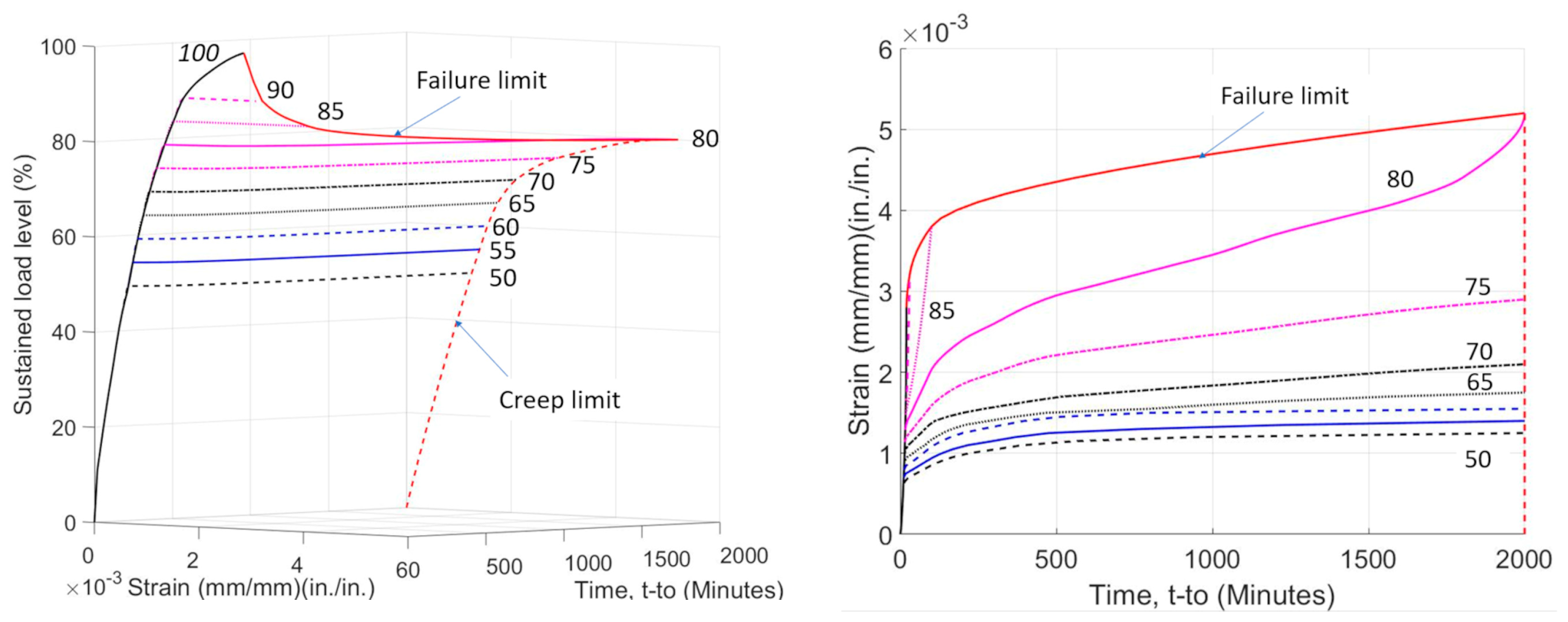
In terms of creep strain kinematics under high constant stresses, concrete experiences three stages of creep: primary, secondary, and tertiary creep, see Figure 1 [1,13,14,15,16]. Stress level dictates whether the concrete will experience all the three stages, or only a subset of them. The primary stage of creep occurs early in the loading history. It is characterized a high early creep rate that steadily decreases with time. Primary creep is generally associated with low stress up to about 40% of short-term compressive strength (f’c). Creep under this level of stress has been the focus of most past research [13,17,18]. The stress level (σc) falls within the elastic domain of concrete response and creep deformations are caused by the breaking and reformation of atomic bonds at various highly stressed sites within the colloidal microstructure of the calcium silicate hydrate gels in the hardened cement paste [19]. At sustained stress levels ≤ ~0.4 f’c, there is a nearly linear relationship between the short-term strains (strain under short-term loading) and delayed creep strains (strains developed with time) and the rate of creep strain development decreases with time [16].
The secondary stage of creep occurs later when creep strains increase with a relatively constant creep strain rate. Under higher compressive stresses (greater than ~0.4 f’c), the concrete undergoes additional damage processes as a result the propagation of microcracks initiated during loading [20,21,22]. Additional nonlinear creep strains are developed as the relationship between the linear creep strain and elastic strain is lost [16].
Tertiary creep is the last stage and generally occurs only when stress become greater than ~0.75 f’c. During this stage, concrete experiences coalescence of microcracks, which ultimately results in concrete failure [16]. The tertiary creep stage is signified by a rapid increase in the creep strain rate.
Many studies [1,12,16,17,20,23,24,25] found that plain concrete subjected to sustained load fails at about 70% to 80% of its short-term strength. Figure 2 shows the effect of level and duration of sustained load on concrete strain [1]. When the sustained stress is lower than 0.75 f’c, microcracks grow slowly [20], creep deformations are limited under infinite loading, and concrete does not fail [1]. When the sustained stress is greater than 0.80 f’c, microcracks grow rapidly [20] and concrete strains increase rapidly so that concrete fails at stresses lower than f’c. Iravani and MacGregor [12] demonstrated that as concrete strength increased, the ratio of sustained load strength to ultimate strength increased.
Tasevski et al. [16] experimentally and theoretically investigated concrete failure under varying strain and stress rates. They investigated the development of linear and nonlinear creep strains, as well as their relationship to material damage and eventual failure. Tasevski et al. [16] concluded that the inelastic strain capacity of concrete governs failure under sustained load, which can be estimated as the difference between the instantaneous post- and pre-peak strains for a given stress level.
Because stresses can be redistributed to the longitudinal reinforcement as the concrete creeps, RC members behave differently from plain concrete under sustained loading. Stress redistribution allows concrete stresses to be decreased, thereby reducing failure likelihood. Moreover, the bond between concrete and reinforcing bar is also affected by sustained load and may contribute to increased deformation or failure. While considerable research has been conducted on long-term deflection of RC beams under service-level sustained loads [26,27,28,29,30,31] or corrosion [32,33,34,35,36], there has been little research on RC members subjected to high-level sustained loads.
High sustained load has been found to negligibly impact the flexural capacity of simply supported beams [37,38], likely because longitudinal bars, rather than concrete, control flexural strength. For shear-controlled beams, a study by Sarskosh et al. [39] showed failure in two beams tested under high sustained loads equal to 98% and 91% of their average short-time shear capacity after 2.5 and 44 h of loading, respectively; however, 16 other beams did not experience failure under sustained loads. The researchers also found that crack widths stabilized after 6 months and subsequent reloading to failure did show a reduction in shear strength due to sustained load. While this test provided valuable information, the beams did not contain compression reinforcement that is typical in many beams and may alter the sustained load behavior. Saifullah et al. [40] tested shear critical beams under very slow loading (160 kN/1000 h) and found that the increase in crack width under sustained load was very small and creep had no effect on concrete shear strength. However, only two specimens were tested under the very slow load rate. Nie and Cai [41] investigated the deflection of eight cracked RC beams under sustained loads ranging from 48 to 88% of capacity. The rate of deflection increase decreased with time with the ratio of the seven day and three-month deflections increments between 16% and 34%. They found that both flexural and shear deflections are significant under sustained loads. As in the other the tests by other researchers, the beams did not contain compression reinforcement.
Tasevski et al. [42] investigated the effect of loading rate on the shear strength of RC beams. Despite the longer load duration (load application time ranging from 7.4 s to 5.7 days), there was no noticeable reduction in beam shear strength. Because the longitudinal bars limited crack opening and maintained aggregate interlock, time-dependent crack growth in an RC beam may be less pronounced than in plain concrete. Shang et al. [43] experimentally evaluated bond strength under sustained loading. In this study, 32 specimens were subjected to different levels of sustained load (25%, 50%, and 75% of short-time capacity) for 120 days under different environmental conditions. The time-dependent slip between concrete and reinforcing bar increased as the level of sustained load increased.
While previous research has shown plain concrete is suspectable to failure under high sustained load, the limited research on RC beams has shown that addition of reinforcement may limit the effect of sustained load on beam failure. However, the experimental data is limited and not all tests considered shear-controlled beams under constant load. This research will provide important additional experimental data on the time-dependent behavior of shear-controlled RC beams under high sustained load.

2. Materials and Methods

Nine RC beams were tested to evaluate their time-dependent strength and stiffness characteristics under high sustained loads. The beams were tested in two different series with differences in tensile reinforcement ratio and shear span length. The research sought to investigate the behavior of shear-controlled beams with a short shear span length as shear failure is more brittle and possibly more susceptible to sustained load failure. The beams had both compression and tension reinforcement to represent typical beam structures. The compression reinforcement would influence the sustained load response as the reinforcement would be able to help to compensate for the concrete creep in compression. The primary parameter in each series was high sustained load level ranging from 82% to 98% of short-term loading capacity. Among the nine beams, two were control specimens (one in each series) and loaded to failure within a short time without experiencing any sustained load.

2.1. Specimen Design

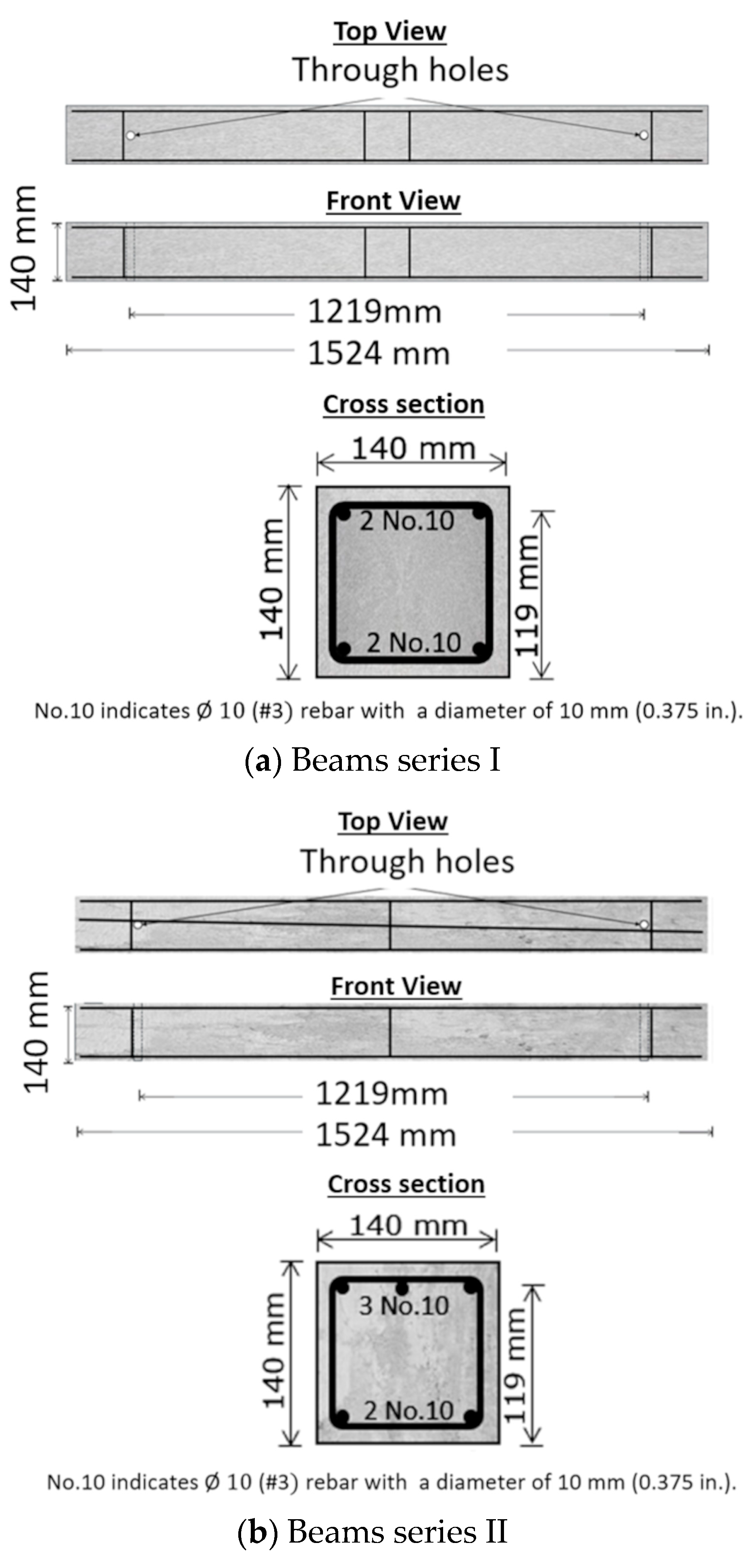
The specimens were constructed with dimensions of 1524 mm × 140 mm × 140 mm (60 in. × 5.5 in. × 5.5 in.), see Figure 3. The beams were at a 0.47 scale to match the scale of ongoing testing of slab-column specimens. The clear concrete cover outside the stirrups was 6.35 mm (0.25 in.). In beam series I, the reinforcement ratio in both the tension and compression zones was 0.86% and the shear span to depth ration (a/d) was 2.9. The point load (P) (see Figure 4) to reach the ACI 318 [44] shear strength in beams series I was 17.28 kN (3884 lb). The load at yield moment was 16.81 kN (3780 lb) and ultimate moment 19.21 kN (4320 lb). Therefore, under short-term loading, the beam flexural reinforcement would be expected to yield before shear failure.
In beam series II, the reinforcement ratio in the tension zone and compression zones was 1.29% and 0.86%, respectively, and the shear span to depth ratio was 4.3. The reinforcement ratio and the shear span length were increased so that shear failure could occur before flexural yielding. The point load (P) to reach the ACI 318 [44] shear capacity was 15.80 kN (3551 lb). The load at the yield moment was 19.31 kN (4340 lb) and ultimate moment 20.01 kN (4500 lb).

2.2. Test Setup

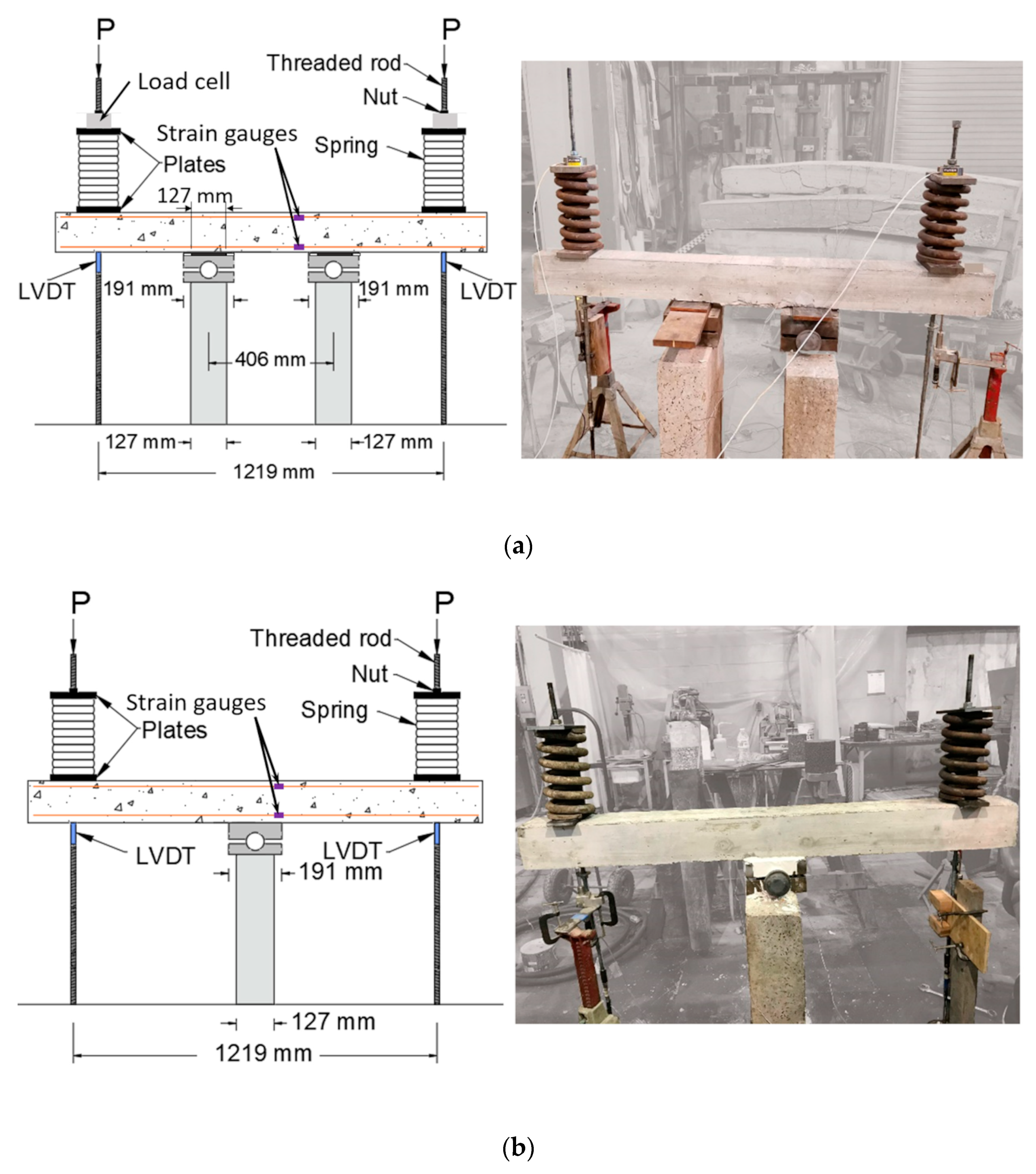
The test setup for both series used a 1219 mm (4 ft) span between loading points. Beam series I used two supports, each located at 1/3 of the span length (Figure 4a). Beam series II used only one support at mid-span (Figure 4b). Each beam had two through holes created by PVC tubes to allow threaded rods to pass through and load the beam. Each threaded rod was connected to the lab strong floor. The load was applied to the beam by turning the nuts on the top of the threaded rods. Coil springs with a stiffness of 0.84 kN/m (4800 lb/in) were added to help maintain a constant applied load.

2.3. Instrumentation

Each specimen was instrumented to provide data needed to understand its response under high sustained loads. Two load cells with 89 kN (20 kip) capacity were placed between the plate and washer at the top of the beam specimen to measure the applied load. In addition, strain gauges were attached to each rod connected to the lab floor to provide an additional measurement of the applied load. The readings from the two systems were consistent. Two linear variable differential transformers (LVDTs) were utilized to determine the vertical deflections of the beam at the loading points. The LVDTs were placed underneath the beam as near as possible to the through-hole and threaded rod. The LVDTs (BDI LVDT-01-005) have a range of ±12.7 mm (0.5 in.) and an accuracy of ±0.025 mm (0.001 in.). Each beam had two strain gauges (one on a tension bar and the other one on a compression bar) attached at a distance of 76 mm (3 in.) longitudinally from beam center. In beam series II, the tension side gauges were attached to the center bar. The strain gages (Vishay C4A-13-125SL-350-39P) have an accuracy of ±10−6 strain.
Table 1 summarizes the specimens’ characteristics, including loading age, sustained load duration, and sustained load intensity. Temperatures and relative humidity were also recorded and are shown in Table 1, which also shows the designation of the test specimens applied with sustained loads. The testing lab had no cooling in the summer so there was a greater variation in the daily temperature for the beams tested in the summer. Furthermore, the temperature and humidity variations more closely replicated the actual conditions of beams in service. Differences in the average temperatures for each test may have significant effects. Higher average temperatures will accelerate creep, while lower temperatures will decelerate creep [1,2]. Temperature variations of 11 °C, as reported during testing, will result in about 5% increase in the temperature correction coefficient used in the CEB-MC90 creep model [1]. Because the tests are short and the specimens have been pre-dried for some time, humidity is unlikely to have a significant effect.

2.4. Material Properties

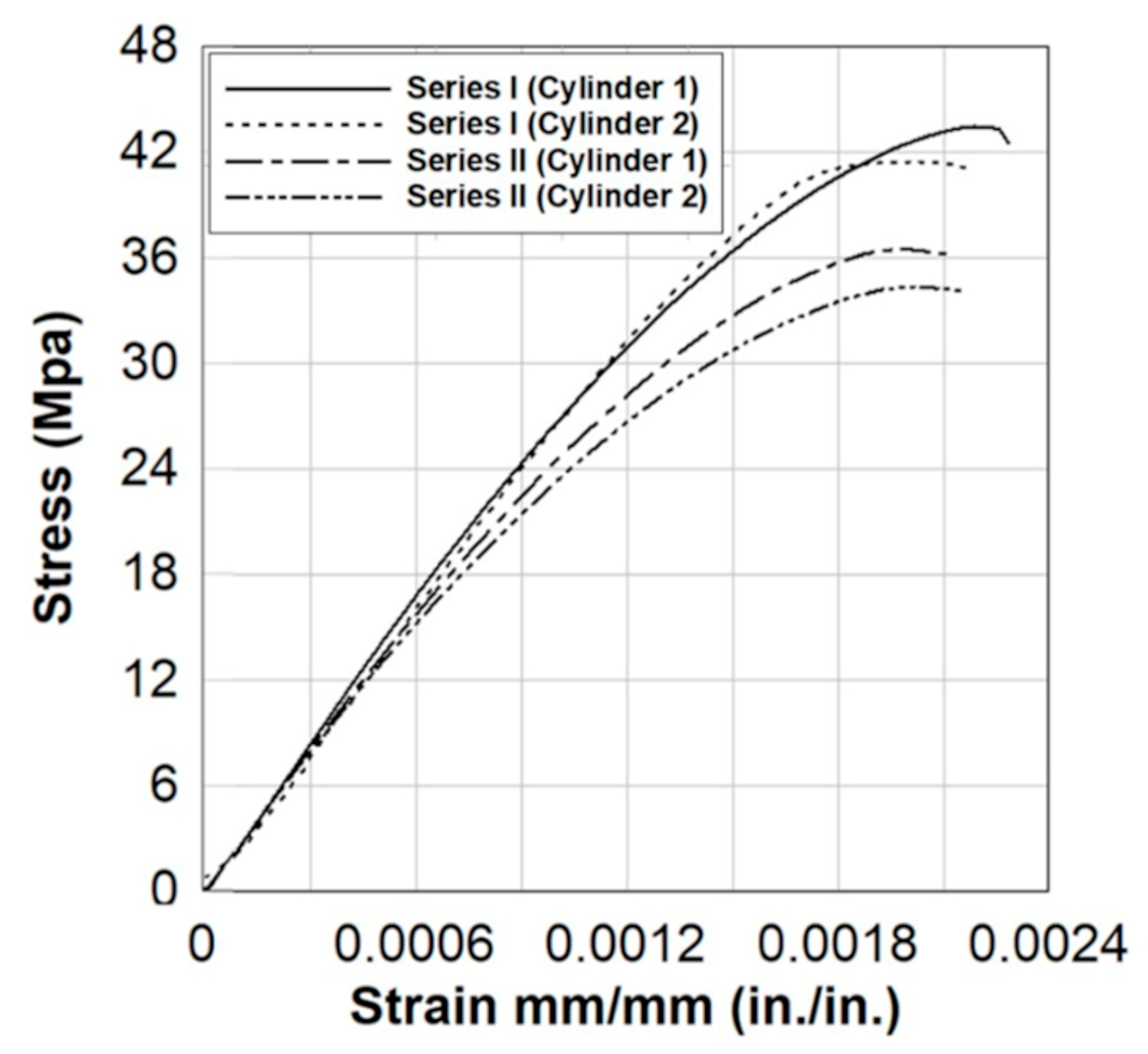
The concrete used in the RC beams was provided by a local ready-mix company and designed to have a cylinder compressive strength of 27.58 MPa (4000 psi). Table 2 shows the concrete mix design for one cubic meter of concrete. The measured concrete slump was 76–101 mm (3–4 in.) in both series. The beams were moist-cured for 7 days and then removed from the formwork and exposed to the environment for further curing before testing. The beams in each series were cast at the same time. Compressive strength was measured at the start of testing. The measured compressive strength of the concrete used in series I at age of 64 days was 42.45 MPa (6157 psi). The measured compressive strength of the concrete used in series II at age of 206 days was 35.45 MPa (5141 psi). The stress–strain curves for four concrete cylinders, two from each series, are shown in Figure 5.
Grade 420 (Grade 60) steel rebars were tested under uniaxial tension according to the specifications of ASTM A370 [45]. Stress–strain curves from two tested reinforcement bars are shown in Figure 6. The average yield strength was 476 MPa (69 ksi), average elasticity modulus was 197 GPa (28,600 ksi), and the average ultimate strength was 718 MPa (104 ksi).

2.5. Testing Procedure

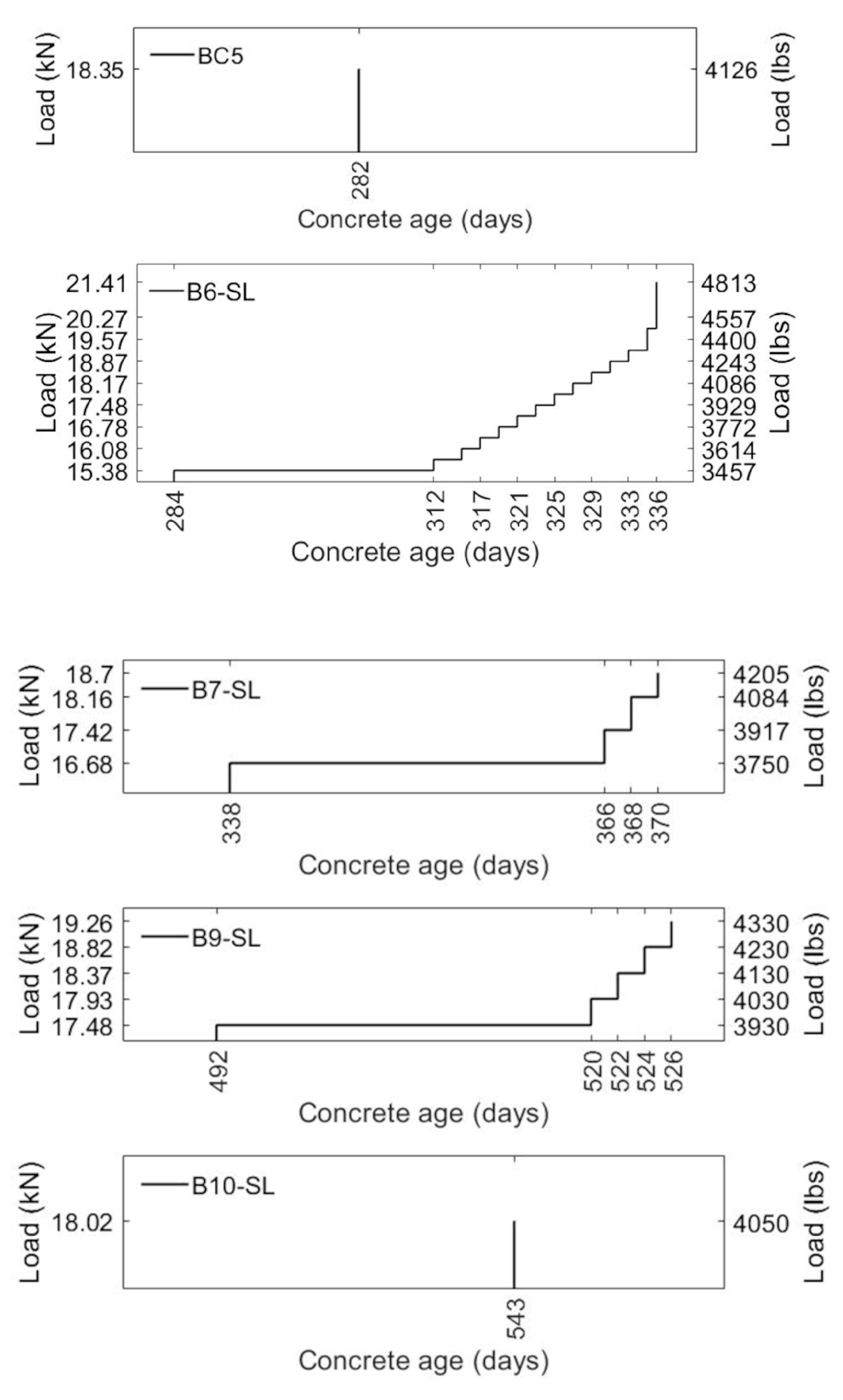
Sustained load specimens were first loaded to a target sustained load within about 20 min (short-term loading). Then, the load was held constant for 24 to 52 days (sustained loading). The target sustained window was 24 days. Although this testing period may seem short for creep testing, the objective of this research was to determine if failure would occur under high sustained load. After 24 days, the rate of deflection increase reduced to less than 0.025 mm/day (0.001 in./day) on average and the research team felt the beam would not fail under additional testing. This was verified by a few specimens that were tested for an extended time period to evaluate behavior beyond 24 days. The applied load was checked and adjusted (if needed) every 12 h for the first 3 days and daily afterwards. For beam series I, after the sustained loading was finished, the beam was loaded to failure in a short time. For beam series II (excluding B10-SL), multiple levels of sustained load were applied. If no failure occurred under sustained load, the load was increased by 2.5 to 5% and then held constant for a time period of 2–3 days. The goal of this stepped loading approach was to determine shear-controlled beam near-failure behavior under sustained load and capture the tertiary phase of creep. Figure 7 and Figure 8 show the details of loading histories.

3. Results

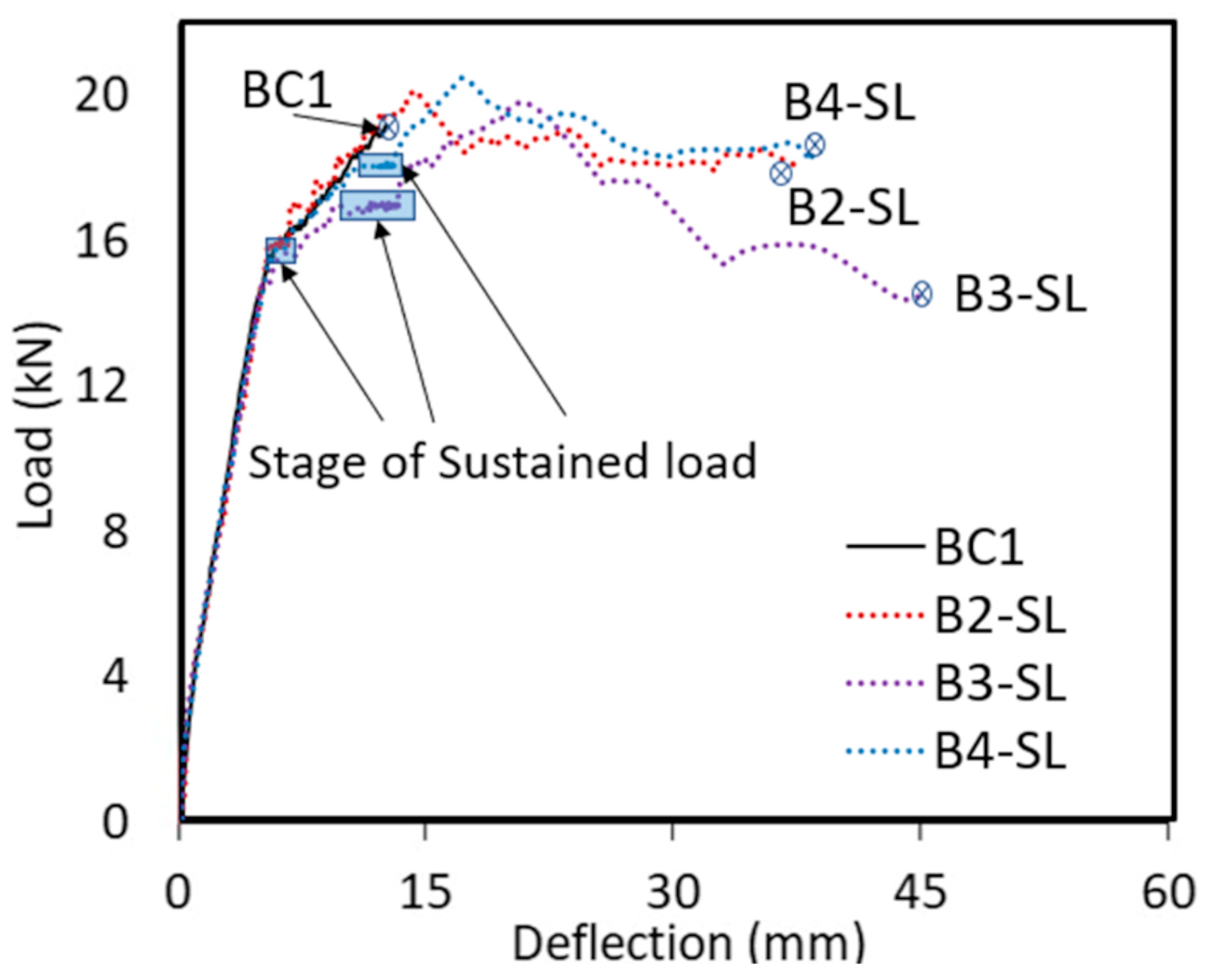
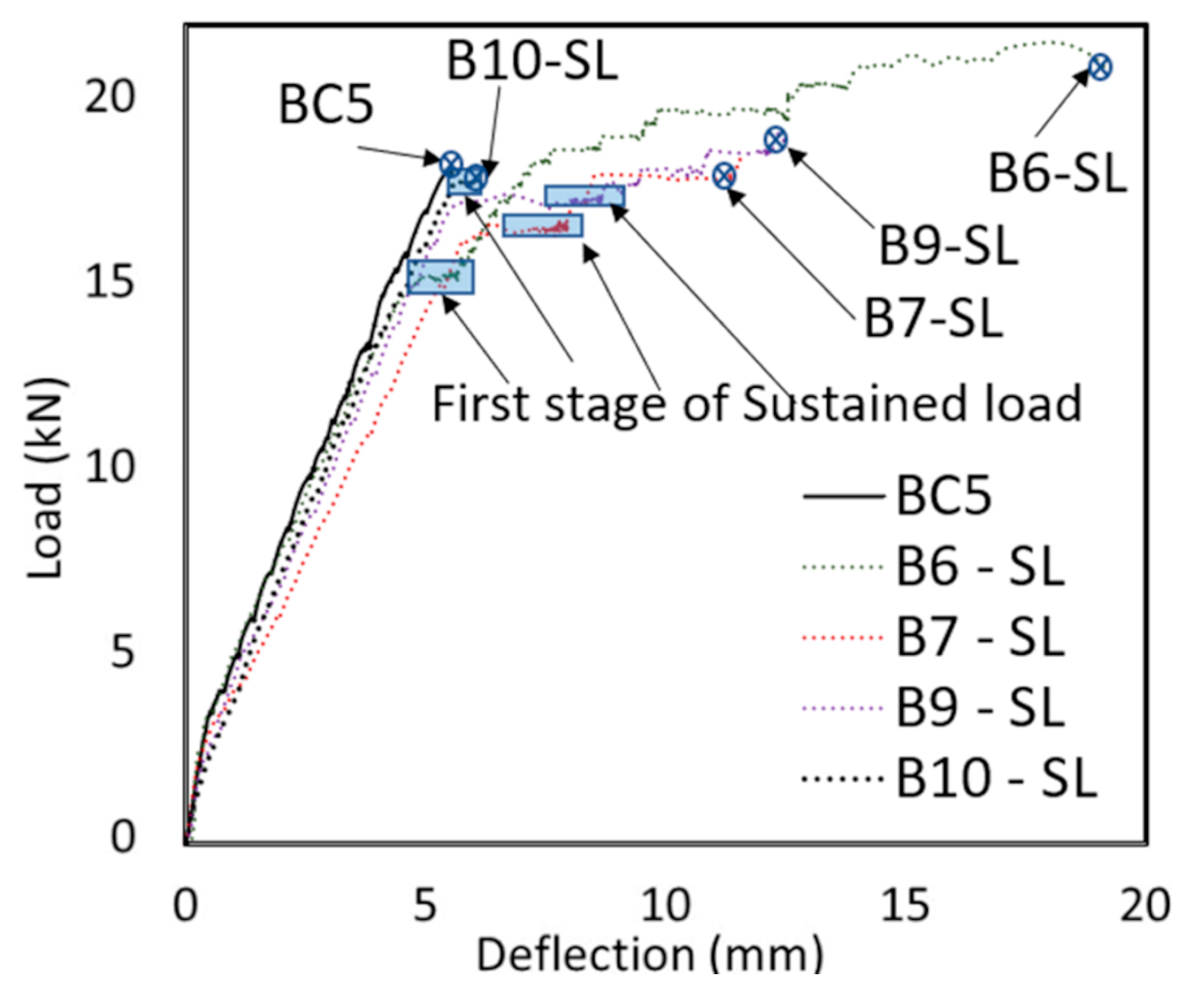
Figure 9 and Figure 10 show the load vs. the average deflection of the two LVDTs for beam series I and II, respectively. During the initial short-time loading, all specimens in series I showed similar behavior. However, there was a 10% variation in the initial stiffness of the beam series II.
Table 3 and Table 4 summarize the results of beam series I and series II including sustained load intensity, defined as the ratio of sustained load to the peak load of the control specimens (BC1 for series I and BC5 for series II). The tables also include the actual sustained load intensity which is the ratio of sustained load to the actual peak load of the specimens. The tables give the failure deflection when a beam experienced a sudden shear failure. In the tables, the creep coefficient is defined as the ratio of deflection increase during sustained loading to the initial deflection. The measured initial deflections, which is the elastic and inelastic deflection experienced in the specimens during the initial short-term loading, are also reported in the tables. The initial loading occurred in a slow process (over 20 min). The initial deflection was defined as the deflection measured at the end of the loading period. The sustained loading period and deflection increase are highlighted in Figure 9 and Figure 10. The figures indicate that the beams that underwent sustained loading showed a load-deflection behavior different from that of the control specimen and much greater deflection at failure.
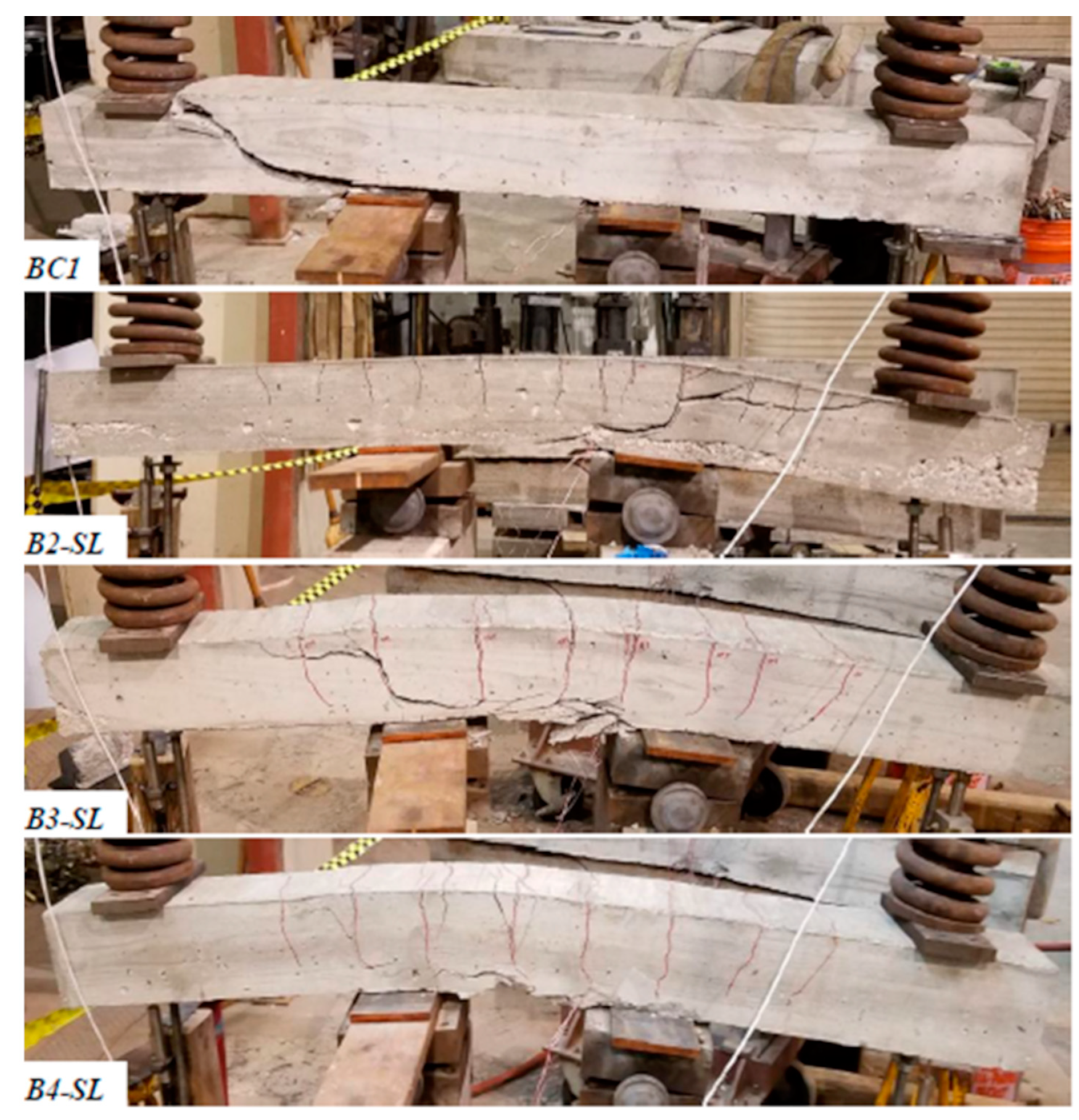
For beams series I, BC1 served as a control specimen and was tested under monotonically increasing load to failure. BC1 failed at a load per loading point (P) of 19.62 kN (4410 lb) and a deflection of 12.75 mm (0.502 in.). The failure mode was a sudden shear-controlled failure, as seen in Figure 11. The remaining beams in series I were loaded with sustained loads equal to 82% (B2-SL), 87% (B3-SL) and 93% (B4-SL) of the strength of the control specimen BC1. Beam B2-SL’s sustained load was near the yield moment, while the others were greater. None of these specimens failed under the sustained loads. During further loading, the beams experienced significant flexural cracking and deflection prior to the sudden final shear failure shown in Figure 11.
BC5 served as a control specimen for beams series II and failed at a load of 18.35 kN. (4216 lb). The failure mode was a sudden shear failure, as shown in Figure 12. The remaining beams in series II were tested under a first stage of sustained load with initial load levels of 84% (B6-SL), 91% (B7-SL), 95% (B9-SL), and 98% (B10-SL) of the strength of BC5. Under increasing levels of short period sustained loads, the shear-controlled beams that experienced sustained load exhibited significant flexural cracking and deflection before a sudden shear failure.
Specimen B10-SL, which was loaded to 98% of beam BC5’s failure, load failed under sustained load (18 kN (3930 lb)) only 84.5 min after the sustained load level was obtained (total time of 104.5 min). All other specimens did not fail during the first stage of sustained load. The test results indicate that to fail under sustained load, the load level must be very close (within 2% in this case) to the short-time capacity. This is a higher capacity than the results by Sarkhosh et al. (2015) in which the beams failed at 91% of the shear capacity. It is possible the compression reinforcement in this series of beams helped to increase the level at which failure would occur under sustained load. The demonstrated that a RC specimen has a significant ability to redistribute loads and thus survive under high sustained loads. In contrast, the failure sustained load level for plain concrete may be as low as 80% [1,12].

4. Discussion

The overall results illustrate the behavior of the beams under high levels of sustained load. The following discussion looks closer at each of the results to understand the time-dependent strength and stiffness characteristics as well as the characteristics of impending failure. This information is vital to understand the behavior of RC beams under high sustained loads.

4.1. Deflection under Sustained Loading

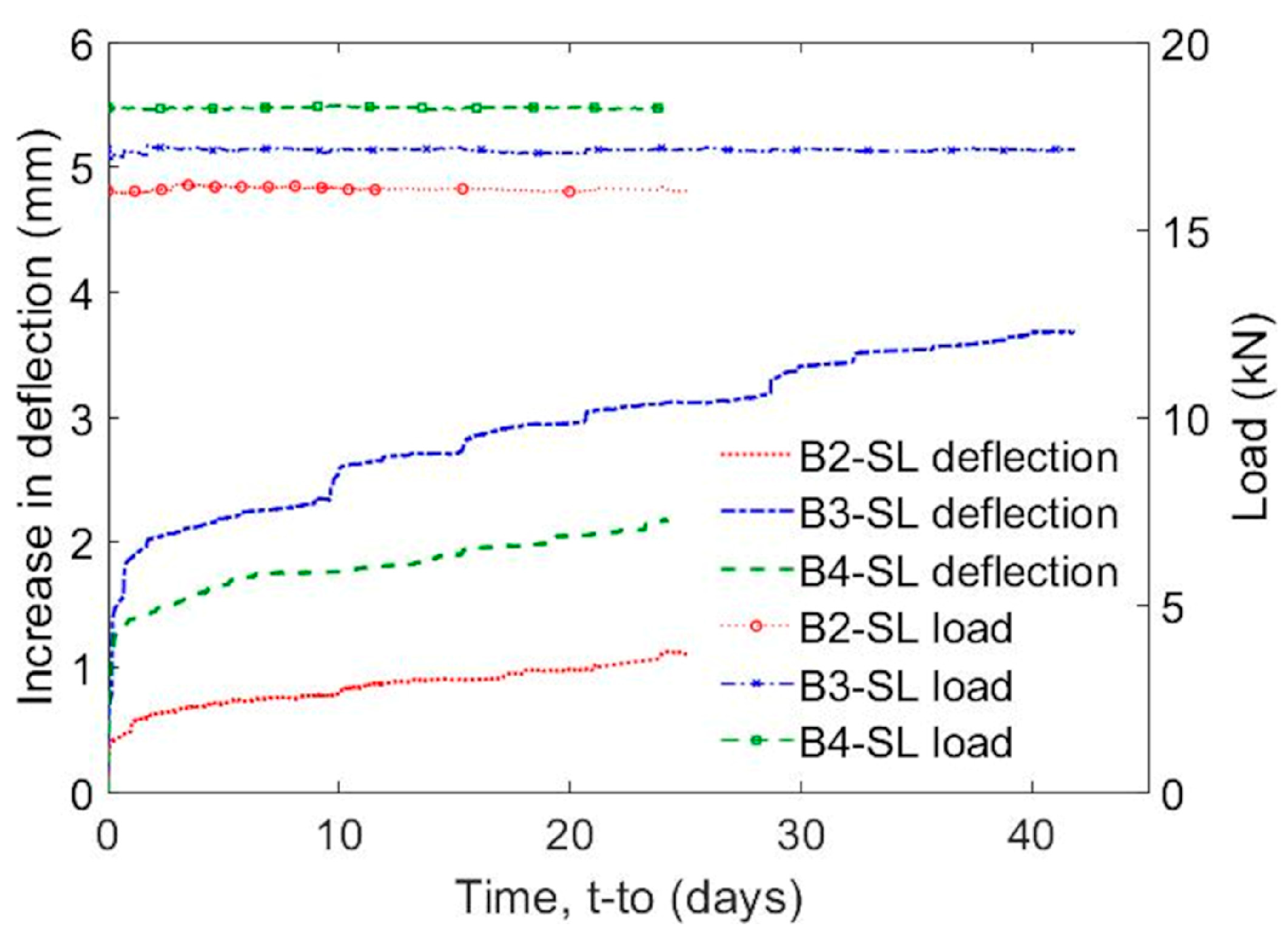
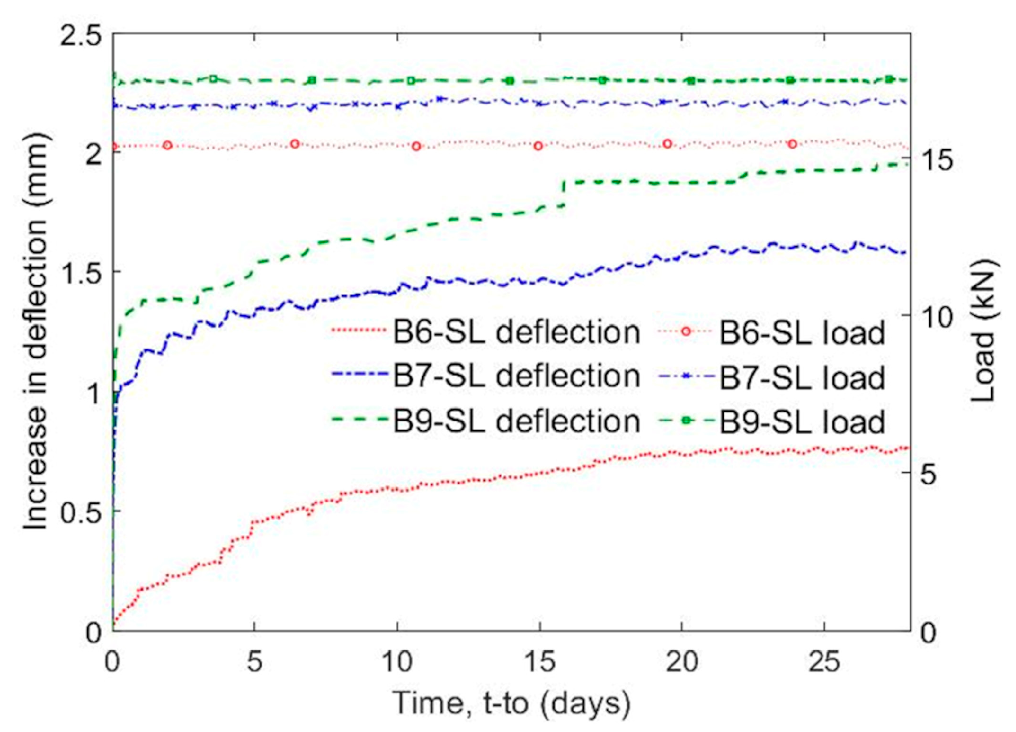
Figure 13 and Figure 14 plot load and deflection time history under sustained loads for the two series of tests. During sustained loading, the deflection of all beams increased. All specimens had the same general behavior which matches the behavior of plain concrete as shown in Figure 1. In the first stage (primary) deflections increased rapidly, and in the second stage (secondary) the deflections increased at a linear rate. Jumps in deflections were due to load adjustments.
During sustained loading, the deflection of B2-SL increased from 5.31 mm to 6.42 mm (21%). B3-SL increased in deflection by 38%. However, B4-SL with the highest sustained load level of 93% increased by only 20.5%. At 24 days, the deflection increases under sustained loading in B2-SL, B3-SL, and B4-SL were 21%, 33%, and 20%, respectively, of the initial deflection. B2-SL was near yield when sustained loading started. This may have led to higher deflections as the reinforcement yielded under sustained load. The post-yielding load-deflection behavior of B3-SL appeared to be softer than that of the other specimens, possibly leading to increased deflection under sustained load. The small difference (0.44 mm) in the total and 24-day deflection for B3-SL shows that the additional 18 days of testing did not result in significant increases in displacement. The deflection at the end of sustained loading of B6-SL, B7-SL, and B9-SL (beam series II) increased by 19%, 25%, and 29%, respectively. At 24 days, the increase in deflection was 18%, 25%, and 28%, respectively. The deflection increase was greater for shear-controlled beams with higher levels of sustained load and demonstrated a more consistent trend than for beam series I, as shown in Figure 15.
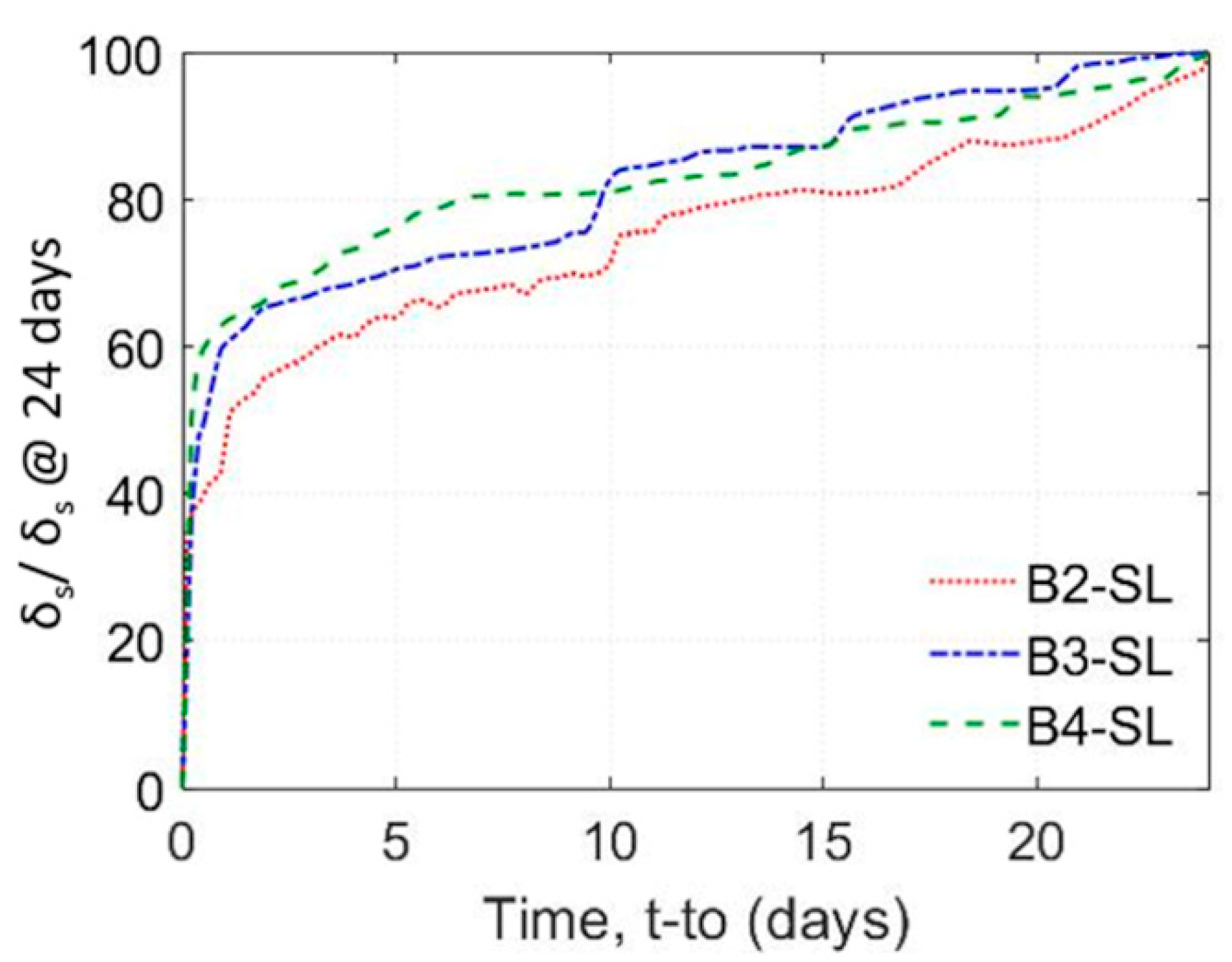
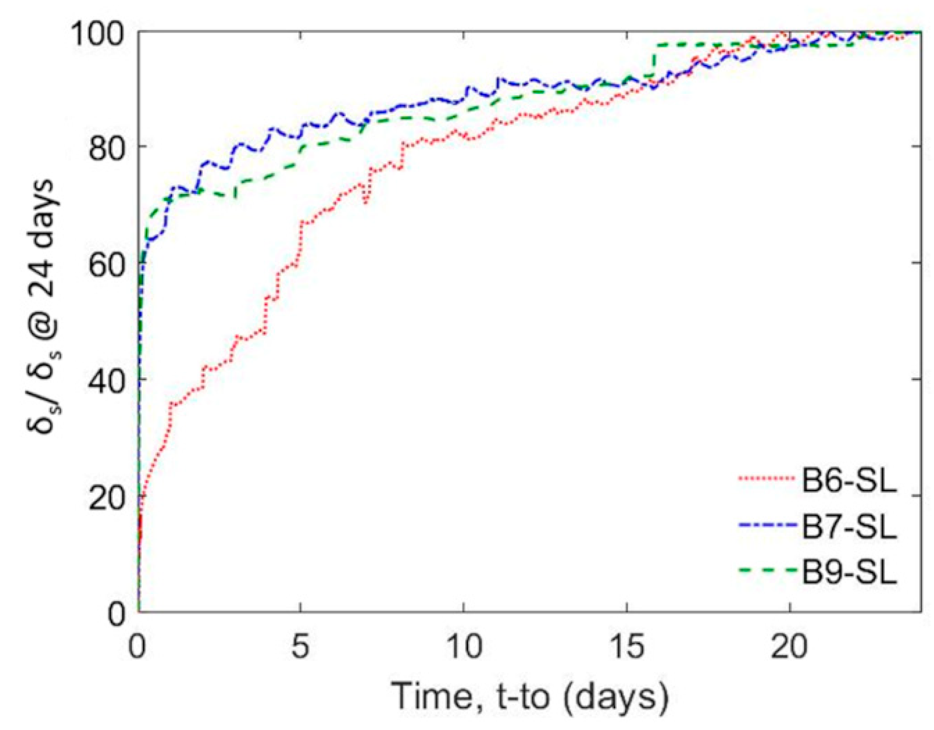
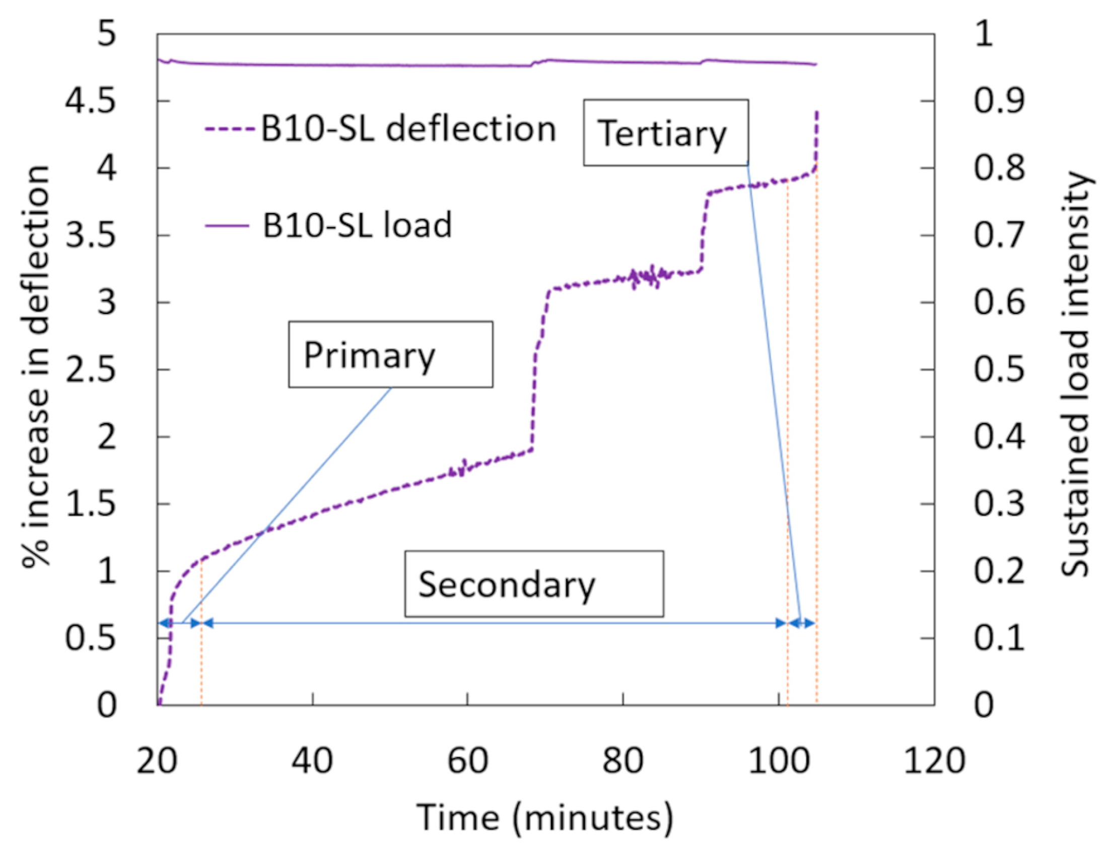
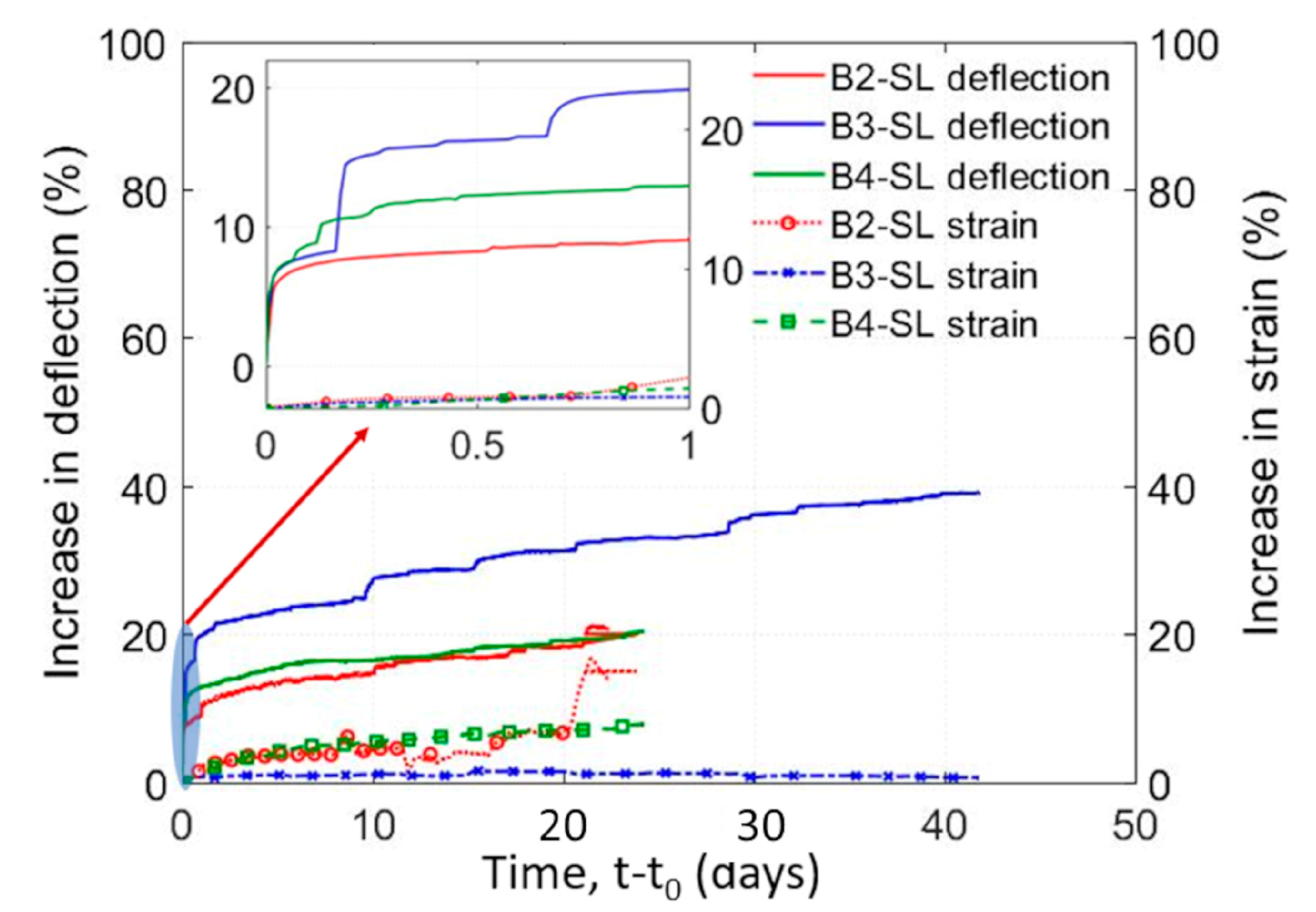
Figure 16 and Figure 17 describe the rate of deflection increase under sustained loading by depicting the additional deflection that occurred under sustained load (δs) divided by the sustained load deflection at 24 days (δs@24 days) for series I and series II. Despite some differences, all specimens show a similar rate of deflection increase with time. Most of the deflection increase took place in the first few days. In the first 24 h for beam series I, 44%, 61%, and 65% of the deflection increase occurred in specimens B2-SL, B3-SL, and B4-SL, respectively. After 7 days, 67%, 72%, and 80% of the deflection increase occurred in these specimens. Moreover, higher sustained load induced greater deflections in the first few days. In the first 24 h for beam series II during the first stage of sustained loading, 35%, 72%, and 71% of the deflection increase occurred in specimens B6-SL, B7-SL, and B9-SL, respectively. Specimen B6-SL experienced the slowest gain in deflection, most likely due to the much lower load level compared to the other specimens (84% vs. >91%). After 7 days, 71%, 85%, and 84% of the 24-day deflection had occurred in the specimens. Again, the results show that most of the deflection increase occurred in the first days of sustained loading. After about 2 days the rate of deflection increase was nearly constant at about 0.025 mm/day (0.001 in./day) for the specimens as expected in the secondary stage of creep. Only specimen B10-SL (series II) reached the third stage (tertiary) and failed under sustained load, as shown in Figure 18. The two earlier increases in deflection were due to load adjustment, while the last increase occurred during tertiary creep with no adjustment in the loading. This stage happened within 2 min before failure.
Beam series 1 was loaded to failure after the period of sustained loading. The beams experienced a peak load at deflections 12%, 65%, and 47% greater than the failure deflection of BC1. The load level then dropped as the concrete crushed on the extreme compression face. The beams then experienced sudden shear failure at deflections 227%, 262%, and 202% greater than BC1. The application of sustained load increased the deflection at sudden shear failure for beam series I by 28.49 mm (1.122 in.) or about 230% greater than BC1.
All beams in series II experienced a sudden shear failure at the peak load. The failure deflections for series II (B10-SL excluded) increased by 230%, 108%, and 122% or by an average of 8.60 mm (0.339 in.) or 150% more than that of BC5. The effect of creep in the concrete under compression during sustained load and possible bond-slip of the tension reinforcement may have allowed for additional deformations to occur before the final shear failure. The increase in deflection at shear failure for both series was significant (190%). In addition, the control experienced sudden shear failure, whereas the sustained specimens experienced significant flexural cracking, which allowed for additional deformation before the shear failure. This may be an indicator of possible structural issues in actual structures.
For beam series II, after the sustained load period, the beam’s load was increased by 2.5 to 6% and held constant for a time period of 2–3 days. The purpose of the stepped loading was to evaluate the near failure behavior of the beams. However, testing time constraints did not allow for a long period of sustained loading. During these stepped loadings, the beam’s deflection increased due to the increase in load and over time during the sustained loading. The rate of deflection increase with time was comparable to the rate at the first stage of sustained loading. B6-SL reached a sustained load of 19.92 kN (4479 lb) (14th stage) for two days without failure. The beam was then loaded to failure and failed at a load of 21.13 kN (4750 lb). The load level was 8% greater than the BC5’s peak load (18.35 kN) (4216 lb) and only 6% greater than the previous loading stage that did not cause failure. B7-SL was subjected to a sustained load (third stage) of 18.16 kN (4084 lb) for two days without failure, which is 3% less than the peak load of the BC5. B7-SL failed during loading the next stage at a load of 18.70 kN (4205 lb) which is only 3% greater that the load level it held for two days in the previous stage. B9-SL was able to resist a sustained load of 18.82 kN (4230 lb) (fourth stage) for two days without failure, which is 0.3% greater than the BC5’s peak load. B9-SL failed in the fifth stage of sustained load after 15.83 min at a load of 19.26 kN (4330 lb), which is 5% greater than the peak load of the BC5 but only 2% greater than the previous loading stage. These results indicate that RC shear-controlled beams may have a much greater ability to withstand sustained loads than plain concrete. The rise in peak load in sustained specimens was attributable to random scatter and continuing time curing.

4.2. Peak Load

In general, the strength of the specimens slightly increased due to the application of sustained load with an average increase of 6.1%. The peak loads of B2-SL, B3-SL, and B4-SL (series I) were 5%, 3%, and 7% higher than the control specimen BC1, respectively. With the exception of B10-SL, the peak loads of B6-SL, B7-SL, and B9-SL (series II) were 18%, 2%, and 5% higher than the control specimen BC5, respectively. The peak load for the control specimens were greater than the ACI 318 [44] and Eurocode2 [46] predicted shear capacity. The peak load for BC1 was 18.36 kN (4352 lb), which was 12% higher than the ACI prediction and 40% higher than the Eurocode2 prediction. The peak load in BC5 was 18.35 kN (4216 lb), which was 19% and 25% higher than that predicted by ACI and Eurocode2, respectively.

4.3. Strain

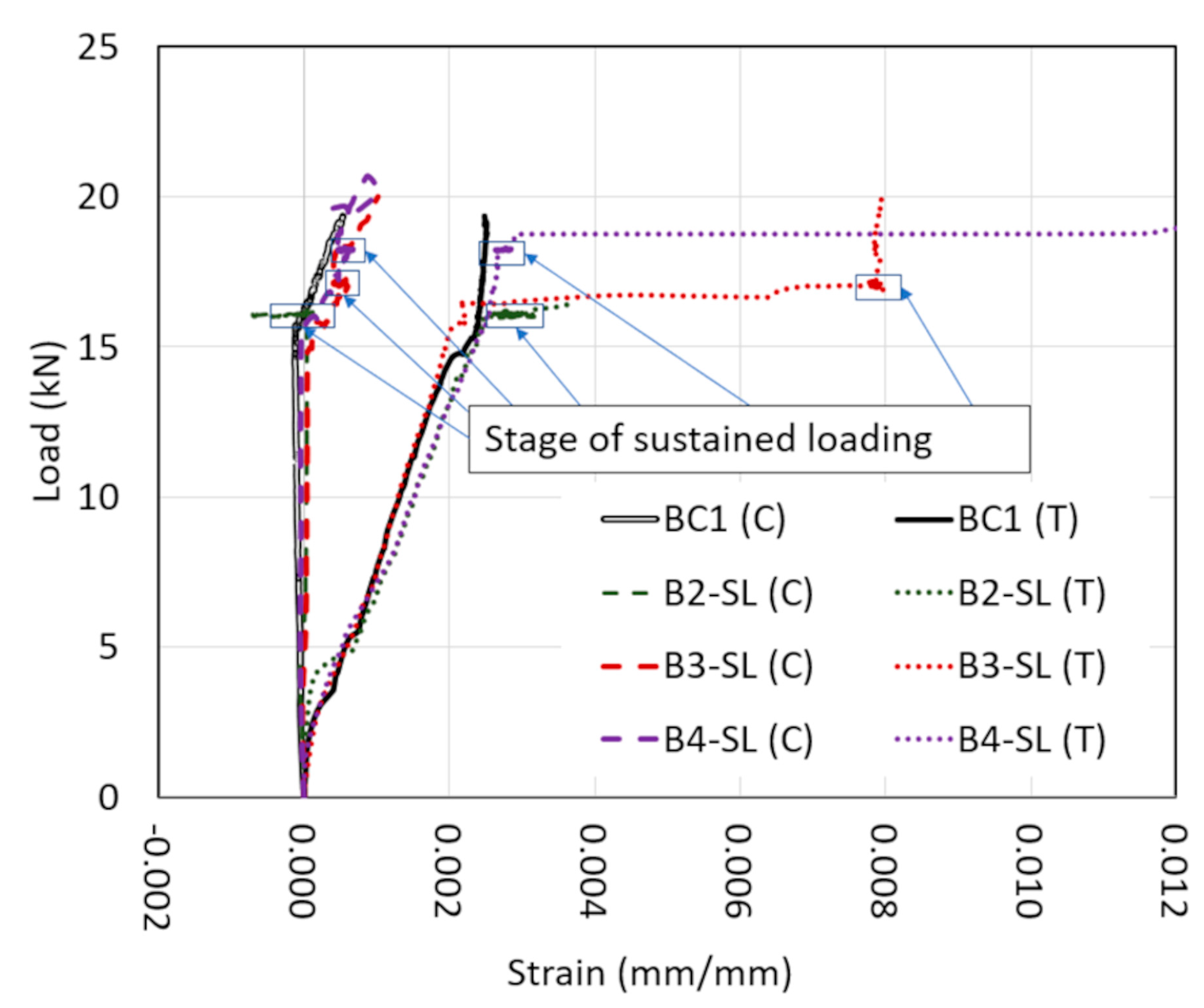
Strain readings followed a similar trend to deflection. Both tension (+) and compression (−) strains increased with the time under sustained load with greater rates of increase earlier in time, as shown in Figure 16, Figure 17, Figure 18, Figure 19, Figure 20, Figure 21 and Figure 22. In series I, the increase in tension strain caused by sustained load was about 0.0005, 0.00007, and 0.0002 mm/mm (in./in.) of the initial tension strain in B2-SL, B3-SL, and B4-SL, respectively. Under sustained load, concrete strain increases due to creep on the compression face which reduces the lever arm for the internal resisting moment. Therefore, in order to sustain the load, the tension force in the reinforcement must increase. The strain increase in B2-SL was greater likely because the reinforcement was near yield at the start of sustained loading. This also likely led to the relatively greater deflection for B2-SL. The strain increase in the compression bars was greater than the bars in the tension. For example, B4-SL experienced an approximately 25% increase in the compression strain under sustained load and a 7% increase in the tension strain.
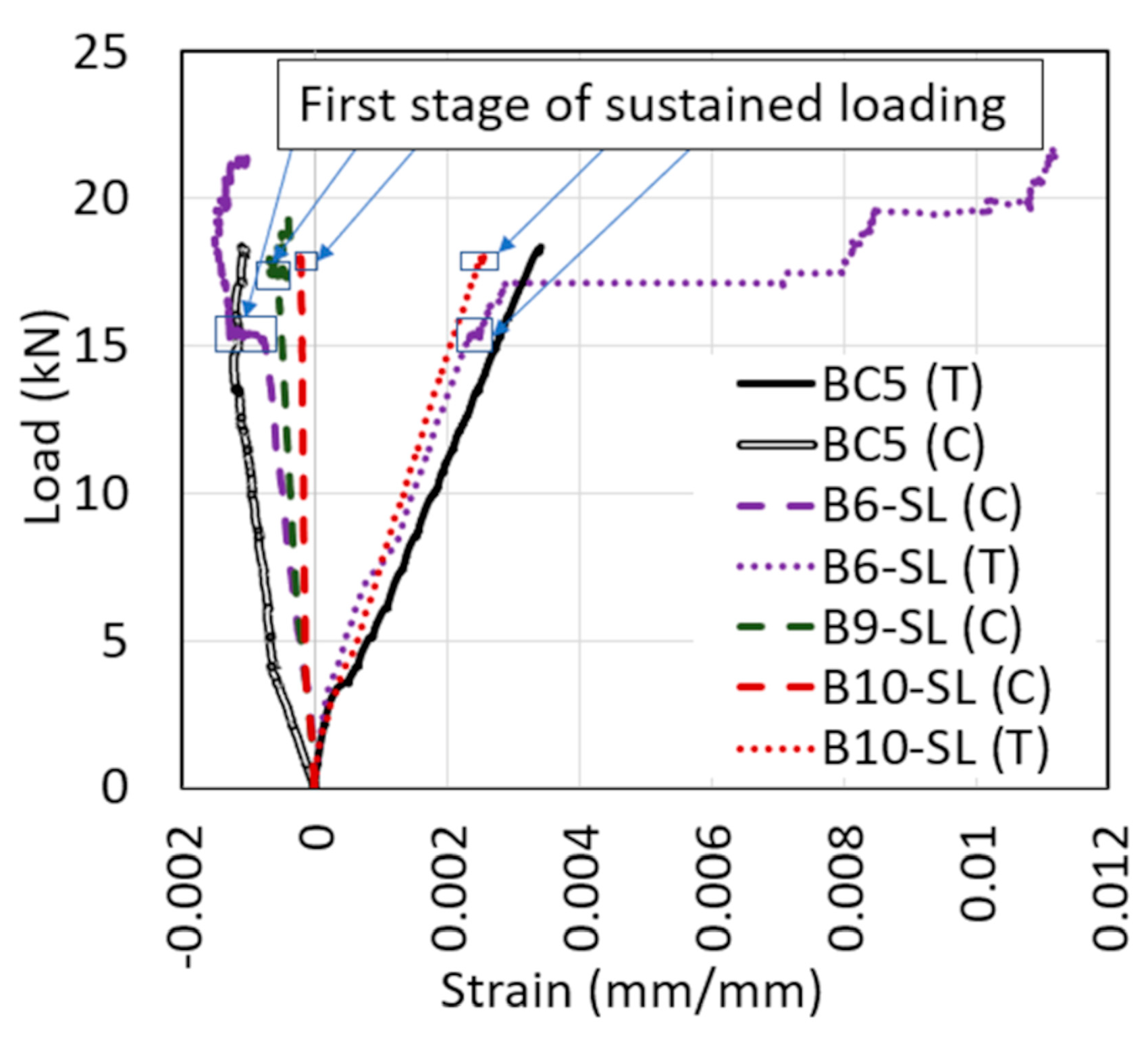
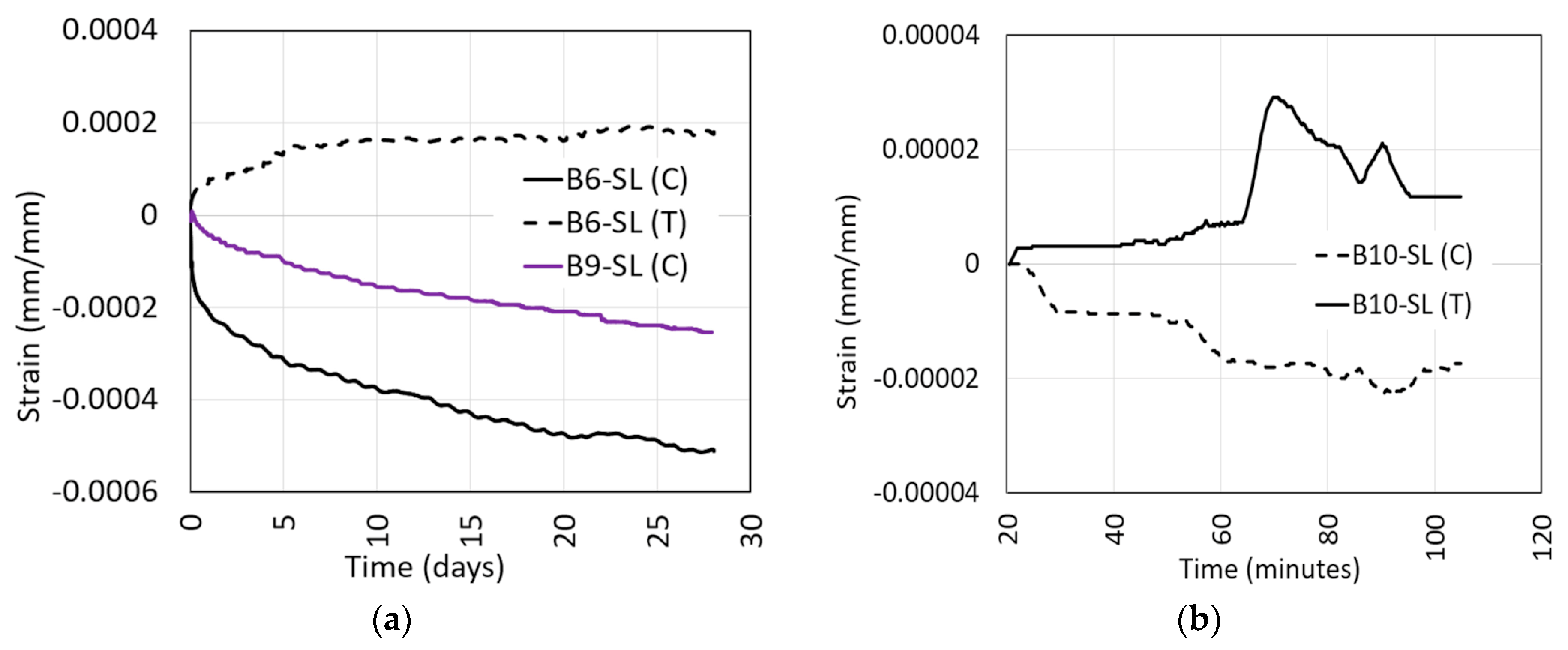
In beams series II, the percent increase in tension strain under sustained load was 17.6% (B6-SL) of the initial strain. The increase in compression strain in B6-SL and B9-SL was 45.5% and 40.6%. Again, the compression strain increase was greater than the tension strain. The percentage of increase was greater for beam series II.

4.4. Deflection vs. Strain

Creep in the concrete under compression during sustained load, possible bond-slip of the tension reinforcement, or cracking and shifting of the neutral axis may have allowed for additional deflection increases to occur early in the response of the beam. In order to evaluate evidence for the early time response, the average of the tension and compression strains under sustained load was compared to the increase in deflection. In the first hours, the percentage increase in deflection was much greater than the percentage increase in strain (see Figure 23).

5. Conclusions

RC shear-controlled beams were tested under high levels of sustained load to evaluate their time-dependent strength and stiffness characteristics. The beams were tested at concrete ages of 67 to 543 days and exposed to high levels of sustained load ranging from 82% to 98% of the short-term capacity for time periods from 24 to 52 days. The experimental work yielded the following conclusions.
  • Even if plain concrete can experience tertiary creep and eventual failure under load levels near 75–80% of its compressive strength, the sustained load level for RC beams to cause failure is very close to their short-term capacity. Only one beam (B10-SL) failed under sustained load at a load level of 98%. Another beam (B9-SL) was able to carry a load level of 95% for 30 days without failure.
  • Deflections increased during sustained loading for all specimens. At 24 days, the increase in deflection was on average 24% of the initial deflection. The increase in deflection was higher for specimens with higher levels of sustained load.
  • On average 55% of the increase in deflection under sustained load took place in the first 24 h. The sharper increase in deflection early in the loading coincided with the primary stage of creep deformations and time-dependent bond slip. The secondary stage exhibited nearly a linear increase in deflection with time. Only specimen B10-SL experienced a tertiary stage that showed a sharp increase in deflection with time just 2 min before failure.
  • Sustained load increased the deflection at shear failure for all specimens. For beams series I, the increase in deflection at shear failure compared to the control specimen was 230% while for beams series II, the increase in deflection was 150%. The large increase in deflection shows that sustained loading can significantly affect the failure behavior of a beam. This large increase in deflection would allow for load redistribution in redundant systems or provide warning signs of impending failure.
  • Shear-controlled beams tested under sustained load showed a different failure behavior from the control specimen that was tested under monotonically increasing load to failure. Unlike the control specimen, which failed brittlely in shear, specimens tested under sustained loads experienced significant increases in deflection and flexural cracking before ultimate shear failure.
  • Both the tensile and compressive strains increased under sustained load. The increase in strain shows that the reinforcement took more of the loading as the concrete softened under the sustained load. The increase in the compression strain was higher than in the tension strain.

Author Contributions

Conceptualization, S.O. and Y.T.; methodology, S.O; formal analysis, M.S.; investigation, M.S.; resources, S.O.; data curation, M.S.; writing—original draft preparation, M.S.; writing—review and editing, A.E.; supervision, S.O.; project administration, S.O.; funding acquisition, S.O. and Y.T. All authors have read and agreed to the published version of the manuscript.

Funding

This paper is based on work supported by the National Science Foundation under Grant No. 1762362 and 1760915. The authors gratefully acknowledge the financial support from the National Science Foundation. The opinions, findings, and conclusions or recommendations expressed in this paper are those of the authors and do not necessarily reflect the views of the sponsor.

Data Availability Statement

The data presented in this study are available on request from the corresponding author.

Conflicts of Interest

The authors declare no conflict of interest.

References

  1. Rüsch, H. Researches toward a general flexural theory for structural concrete. J. Am. Concr. Inst. 1960, 57, 1–28. [Google Scholar] [CrossRef]
  2. Wardhana, K.; Hadipriono, F.C. Study of Recent Building Failures in the United States. J. Perform. Constr. Facil. 2003, 17, 151–158. [Google Scholar] [CrossRef] [Green Version]
  3. Eldukair, Z.A.; Ayyub, B.M. Analysis of Recent U.S. Structural and Construction Failures. J. Perform. Constr. Facil. 1991, 5, 57–73. [Google Scholar] [CrossRef]
  4. USGS. New Earthquake Hazards Program. 2016. Available online: https://www.usgs.gov/natural-hazards/earthquake-hazards/lists-maps-and-statistics (accessed on 4 April 2020).
  5. Hadipriono, F.C. Analysis of Events in Recent Structural Failures. J. Struct. Eng. 1985, 111, 1468–1481. [Google Scholar] [CrossRef]
  6. Gabrielle, L. TWC News, Structural Engineer: Ramp Likely Showed Signs of Deterioration Prior to Collapse, Spectrum News. 2015. Available online: https://spectrumlocalnews.com/nys/binghamton/news/2015/07/17/johnson-city-parking-garage-collapse-friday (accessed on 4 April 2020).
  7. Hill, B.; Kuykendall, R.; Moore, M. Final Report to Merlin Law Group on 4th Floor Distress of Dolphin Towers WJE No. 2010.3594; Wiss, J., Ed.; Elstner Associates, Inc.: Duluth, GA, USA, 2011. [Google Scholar]
  8. Baker, M.; Singhvi, A.; Mazzei, P. Engineer Warned of ‘Major Structural Damage’ at Florida Condo Complex. The New York Times. 26 June 2021. Available online: https://www.nytimes.com/2021/06/26/us/miami-building-collapse-investigation.html (accessed on 14 April 2022).
  9. Morrill, K.B.; Sheffield, C.S.; Kersul, A.M.; Crawford, J.E.; Brewer, T.R.; Lan, S. Calculations of the response of a flat plate structure to a column removal. In Proceedings of the 24th International Symposium on Military Aspects of Blast and Shock, Halifax, NS, Canada, 18–23 September 2016. [Google Scholar]
  10. Mazzotti, C.; Savoia, M. Nonlinear creep, poisson’s ratio, and creep-damage interaction of concrete in compression. ACI Mater. J. 2002, 99, 450–457. [Google Scholar] [CrossRef]
  11. Bažant, Z.P. Theory of creep and shrinkage in concrete structures: A précis of recent developments. Mech. Today 1975, 2, 1–93. [Google Scholar] [CrossRef]
  12. Iravani, S.; MacGregor, J.G. Sustained load strength and short-term strain behavior of high-strength concrete. ACI Mater. J. 1998, 95, 636–647. [Google Scholar] [CrossRef]
  13. Zhou, F.P. Time-Dependent Crack Growth and Fracture in Concrete (No. LUTVDG/TVBM--1011-1-132-1992); Department of Building Technology, Lund University: Lund, Sweden, 1992. [Google Scholar]
  14. Berthollet, A.; Georgin, J.R. Fluage tertiaire du béton en Traction, U. 2004, Tertiary creep of concrete in tension. Fr. Civ. Eng. Rev. 2004, 8.2–8.3, 235–260. [Google Scholar]
  15. Bockhold, J.; Stangenberg, F. Modellierung des nichtlinearen Kriechens von Beton. Beton-Und Stahlbetonbau 2004, 99, 209–216. [Google Scholar] [CrossRef]
  16. Tasevski, D.; Ruiz, M.F.; Muttoni, A. Compressive Strength and Deformation Capacity of Concrete under Sustained Loading and Low Stress Rates. J. Adv. Concr. Technol. 2018, 16, 396–415. [Google Scholar] [CrossRef] [Green Version]
  17. Ruiz, M.F.; Muttoni, A.; Gambarova, P.G. Relationship between Nonlinear Creep and Cracking of Concrete under Uniaxial Compression. J. Adv. Concr. Technol. 2007, 5, 383–393. [Google Scholar] [CrossRef] [Green Version]
  18. El-Kashif, K.F.; Maekawa, K. Time-Dependent Nonlinearity of Compression Softening in Concrete. J. Adv. Concr. Technol. 2004, 2, 233–247. [Google Scholar] [CrossRef] [Green Version]
  19. Bažant, Z.P.; Jirásek, M. Creep and hygrothermal effects in concrete structures. In Solid Mechanics and Its Applications; Springer: Dordrecht, The Netherlands, 2018. [Google Scholar]
  20. Shah, S.P.; Chandra, S. Fracture of concrete subjected to cyclic and sustained loading. ACI J. Proc. 1970, 67, 739–758. [Google Scholar]
  21. Rossi, P.; Tailhan, J.-L.; Le Maou, F. Comparison of concrete creep in tension and in compression: Influence of concrete age at loading and drying conditions. Cem. Concr. Res. 2013, 51, 78–84. [Google Scholar] [CrossRef]
  22. Tasevski, D.; Muttoni, A.; Ruiz, M.F. Time-Dependent Strength of Concrete in Compression and Shear (No. THESIS); EPFL: Lausanne, Switzerland, 2019. [Google Scholar]
  23. Smadi, M.M.; Slate, F.O.; Nilson, A.H. High-, medium-, and low-strength concretes subject to sustained overloads—Strains, strengths, and failure mechanisms. ACI J. 1985, 82, 657–664. [Google Scholar]
  24. Stockl, S. Strength of concrete under uniaxial sustained loading. Spec. Publ. 1972, 34, 313–326. [Google Scholar]
  25. Awad, M.E.; Hilsdorf, H.K. Strength and Deformation Characteristics of Plain Concrete Subjected to High Repeated and Sustained Loads; University of Illinois: Urbana, IL, USA, 1971. [Google Scholar]
  26. Paulson, K.A.; Nilson, A.H.; Hover, K.C. Long-term deflection of high-strength concrete beams. ACI Mater. J. 1991, 88, 197–206. [Google Scholar]
  27. Espion, B.; Halleux, P. Long-term deflections of reinforced concrete beams: Reconsideration of their validity. ACI Struct. J. 1990, 87, 232–236. [Google Scholar]
  28. Alwis, W.A.M.; Olorunniwo, A.; Ang, K.K. Long-term deflection of RC beams. J. Struct. Eng. 1994, 120, 2220–2226. [Google Scholar]
  29. Alwis, W.A.M. Long-term deflection of RC beams under constant loads. Eng. Struct. 1999, 21, 168–175. [Google Scholar] [CrossRef]
  30. Samra, R.M. Renewed assessment of creep and shrinkage effects in reinforced concrete beams. ACI Struct. J. 1997, 94, 745–751. [Google Scholar]
  31. Bakoss, S.L.; Gilbert, R.I.; Faulkes, K.A.; Pulmano, V.A. Long-term deflections of reinforced concrete beams. Mag. Concr. Res. 1982, 34, 203–212. [Google Scholar] [CrossRef]
  32. Dekoster, M.; Buyle-Bodin, F.; Maurel, O.; Delmas, Y. Modelling of the flexural behaviour of RC beams subjected to localised and uniform corrosion. Eng. Struct. 2003, 25, 1333–1341. [Google Scholar] [CrossRef]
  33. Choi, W.-C.; Yun, H.D. Long-term deflection and flexural behavior of reinforced concrete beams with recycled aggregate. Mater. Des. 2013, 51, 742–750. [Google Scholar] [CrossRef]
  34. Du, Y.; Cullen, M.; Li, C. Structural performance of RC beams under simultaneous loading and reinforcement corrosion. Constr. Build. Mater. 2013, 38, 472–481. [Google Scholar] [CrossRef]
  35. Yu, L.; Francois, R.; Dang, V.H.; L’Hostis, V.; Gagné, R. Structural performance of RC beams damaged by natural corrosion under sustained loading in a chloride environment. Eng. Struct. 2015, 96, 30–40. [Google Scholar] [CrossRef]
  36. Liu, Y.; Jiang, N.; Deng, Y.; Ma, Y.; Zhang, H.; Li, M. Flexural experiment and stiffness investigation of reinforced concrete beam under chloride penetration and sustained loading. Constr. Build. Mater. 2016, 117, 302–310. [Google Scholar] [CrossRef] [Green Version]
  37. Washa, G.W.; Fluck, P.G. Effect of sustained overload on the strength and plastic flow of reinforced concrete beams. ACI J. Proc. 1953, 50, 65–72. [Google Scholar]
  38. Reybrouck, N.; Criel, P.; Caspeele, R.; Taerwe, L. Modelling of Long-Term Loading Tests on Reinforced Concrete Beams; ASCE: Vienna, Austria, 2015; pp. 745–753. [Google Scholar] [CrossRef] [Green Version]
  39. Sarkhosh, R.; Walraven, J.; den Uijl, J. Shear-critical reinforced concrete beams under sustained loading Part I: Experiments. Heron 2015, 60, 181–205. [Google Scholar]
  40. Saifullah, H.A.; Nakarai, K.; Piseth, V.; Chijiwa, N.; Maekawa, K. Shear Creep Failures of Reinforced Concrete Slender Beams without Shear Reinforcement. ACI Struct. J. 2017, 114, 1581–1590. [Google Scholar] [CrossRef]
  41. Nie, J.; Cai, C.S. Deflection of Cracked RC Beams under Sustained Loading. J. Struct. Eng. 2000, 126, 708–716. [Google Scholar] [CrossRef]
  42. Tasevski, D.; Ruiz, M.F.; Muttoni, A. Influence of Load Duration on Shear Strength of Reinforced Concrete Members. ACI Struct. J. 2020, 117, 157–170. [Google Scholar] [CrossRef]
  43. Shang, H.; Ren, G.; Hou, D.; Zhang, P.; Zhao, T. Bond behaviour between steel bar and concrete under sustained load and dry–wet cycles. Mag. Concr. Res. 2019, 71, 700–709. [Google Scholar] [CrossRef]
  44. ACI Committee 318, Building Code Requirements for Structural Concrete; American Concrete Institute: Farmington Hills, MI, USA, 2014.
  45. ASTM A370-21; Standard Test Methods and Definitions for Mechanical Testing of Steel Products. ASTM International: West Conshohocken, PA, USA, 2021.
  46. EN 1992-1-1; Eurocode 2: Design of Concrete Structures—Part 1-1: General Rules and Rules for Buildings. CEB. European Committee for Standardization: Brussels, Belgium, 2011.
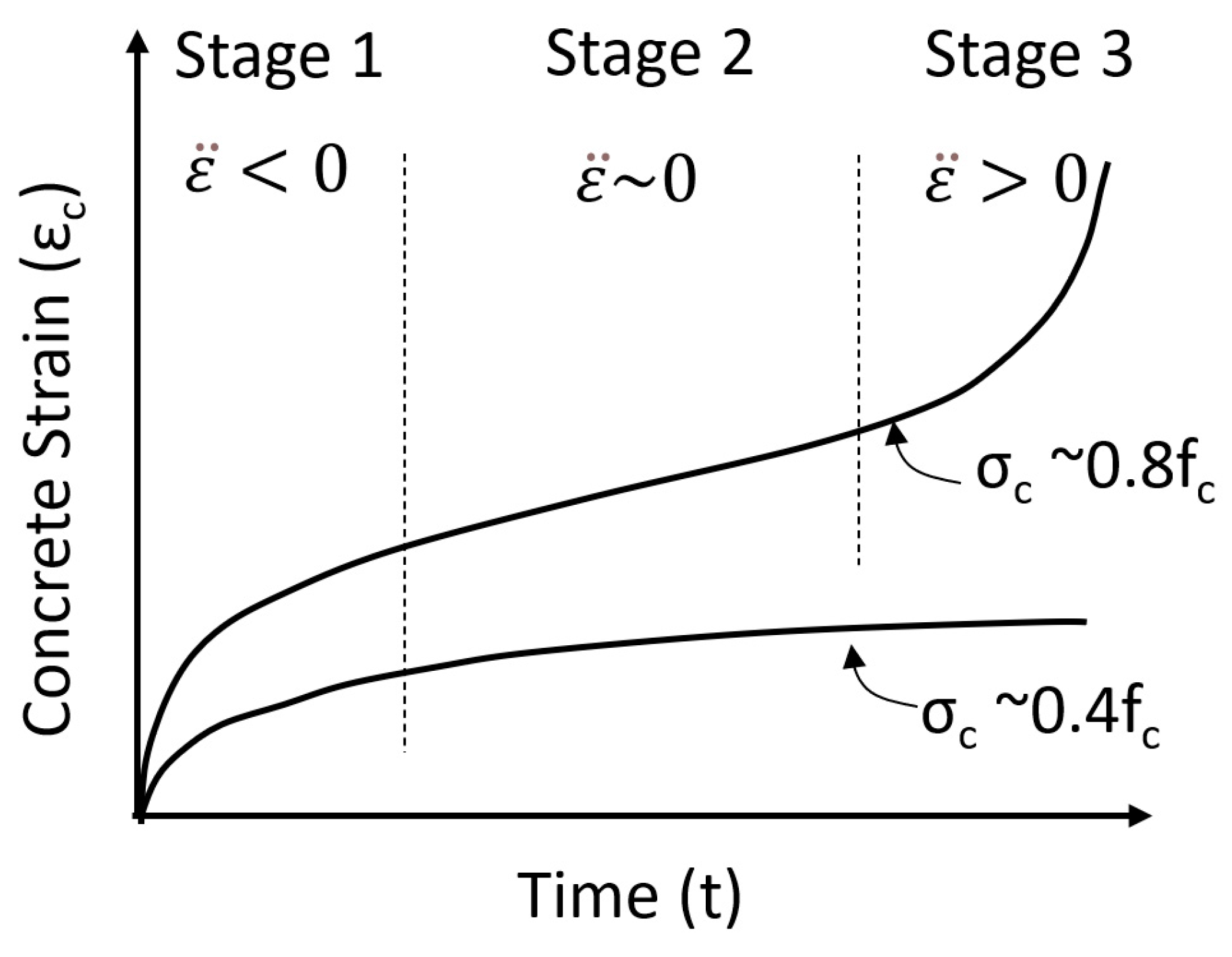
Figure 1. Evolution of creep strains with time (primary, secondary, and tertiary stages of creep).
Applsci 12 04015 g001
Figure 2. Effect of sustained stress level and duration on the concrete strain (adapted from Rüsch [1]).
Applsci 12 04015 g002
Figure 3. Beam reinforcing details: (a) series I and (b) series II.
Applsci 12 04015 g003
Figure 4. Test setup for (a) beam series I and (b) beam series II.
Applsci 12 04015 g004
Figure 5. Stress–strain curves for concrete (1 MPa = 145.04 psi).
Applsci 12 04015 g005
Figure 6. Stress–strain curves for longitudinal reinforcement.
Applsci 12 04015 g006
Figure 7. Beam series I loading histories.
Applsci 12 04015 g007
Figure 8. Beam series II loading histories.
Applsci 12 04015 g008
Figure 9. Load vs. deflection response of beam series I.
Applsci 12 04015 g009
Figure 10. Load vs. deflection response of beam series II.
Applsci 12 04015 g010
Figure 11. Beam series I failures.
Applsci 12 04015 g011
Figure 12. Beam series II failures.
Applsci 12 04015 g012
Figure 13. Sustained load and deflection with time for the first stage (series I).
Applsci 12 04015 g013
Figure 14. Sustained load and deflection with the time for the first stage (series II).
Applsci 12 04015 g014
Figure 15. Deflection increases vs. sustained load intensity after 24 days of sustained load.
Applsci 12 04015 g015
Figure 16. Percent increase in deflection with time beams series I.
Applsci 12 04015 g016
Figure 17. Percent increase in deflection with time beams series II.
Applsci 12 04015 g017
Figure 18. Percent increase in deflection with time for specimen B10-SL.
Applsci 12 04015 g018
Figure 19. Load vs. strain for beams series I.
Applsci 12 04015 g019
Figure 20. Strain increase with time during sustained loading for series I.
Applsci 12 04015 g020
Figure 21. Load vs. strain for beams series II.
Applsci 12 04015 g021
Figure 22. Strain increase with time during the first stage of sustained loading for beams series II. (a) Specimens B6-SL and B9-SL (b) Specimen B10-SL.
Applsci 12 04015 g022
Figure 23. Increase in deflection and strain under sustained load (beams series I).
Applsci 12 04015 g023
Table 1. Specimen summary including temperature and relative humidity during testing.
SeriesSpecimenLoading Age to (Days)Duration tdTemperature
°C (°F)
Relative Humidity %
Series IBC164---
B2-SL6525 days15.4 ± 3.7 (59.7 ± 6.7)NA
B3-SL9142 days13.3 ± 2.7 (56.0 ± 4.9)NA
B4-SL13524 days16.5 ± 3.7 (61.7 ± 6.7)NA
Series IIBC5282---
B6-SL28432 days26.1 ± 2.5 (79.0 ± 4.5)73.5 ± 3.6
B7-SL33852 days26.4 ± 3.6 (79.5 ± 6.5)72 ± 7
B9-SL49234 days17.1 ± 5.9 (62.8 ± 10.7)28.1 ± 17.1
B10-SL54384.5 min.12.6 (54.6)22.6
Table 2. Concrete Mix Design per m3 (yd3).
Material3/8” Limestone
kg (lb)
River Sand
kg (lb)
Type I Cement
kg (lb)
Air
L (oz)
Retarder
L (oz)
Water
L (gal)
Amount1067.64
(2354)
831.07
(1831)
333.45
(738)
0.135
(4.6)
0.843
(28.5)
133.68
(35.3)
Table 3. Beam series I test matrix and results.
SpecimenBC1B2-SLB3-SLB4-SL
Sustained load kN (lb)-16.01 (3600)17.13 (3850)18.24 (4100)
Sustained load intensity
(sustained load/peak load of BC1)
-0.820.870.93
Actual sustained load intensity
(sustained load/measured peak load)
-0.790.860.88
Peak load kN (lb)18.36 (4352)20.28 (4559)20.01 (4498)20.68 (4659)
Ratio of the peak load to the peak load of BC111.051.031.07
Deflection at the peak load mm (in.)12.37 (0.487)13.88 (0.547)20.47 (0.806)18.22 (0.717)
Deflection at failure mm (in.)12.37 (0.487)40.39 (1.590)44.78 (1.763)37.41 (1.473)
Initial deflection under short-term loading deflection (δi) mm (in.)-5.31 (0.209)9.42 (0.371)10.66 (0.420)
Deflection increase under sustained load (δs) mm (in.)-1.11 (0.043)3.55 (0.140)2.18 (0.085)
Creep coefficient—Ratio sustained to initial deflection (δsi)-0.210.380.20
Rotation under sustained load-0.00270.00870.0054
Sustained load deflection at 24 days (δs@24 days) mm (in.)-1.11 (0.043)3.11 (0.122)2.18 (0.085)
Rotation at 24 days under sustained load-0.00270.00750.0054
Note: the load reported in this table is the point load (P).
Table 4. Beam series II test matrix and results.
SpecimenBC5B6-SLB7-SLB9-SLB10-SL
Sustained load kN (lb)-15.35 (3750)16.68 (3450)17.48 (3750)18.02 (4050)
The reinforcement depth mm (in.)116 (4.573)112 (4.412)112 (4.423)111 (4.357)114 (4.473)
Sustained load intensity
(sustained load/peak load of BC1)
-0.840.910.950.98
Actual sustained load intensity
(sustained load/measured peak load)
-0.710.890.911.00
Peak load kN (lb)18.35 (4216)21.75 (4889)18.70 (4205)19.26 (4330)18.02 (4050)
Ratio of the peak load to the peak load of BC511.181.021.050.98
Deflection at the peak and failure mm (in.)5.64 (0.222)18.45 (0.727)11.76 (0.463)12.52 (0.493)6.13 (0.241)
Initial deflection under short-term loading deflection (δi) mm (in.)-4.98 (0.196)6.45 (0.254)6.84 (0.269)5.87 (0.231)
Deflection under sustained load (δs) mm (in.)-0.91 (0.036)1.60 (0.063)1.95 (0.077)0.26 (0.010)
Creep coefficient—Ratio sustained to initial deflection (δsi)-0.190.250.290.05
Rotation under sustained load-0.00150.00260.00320.00043
Sustained load deflection at 24 days (δs@24 days) mm (in.)-0.90 (0.035)1.58 (0.062)1.92 (0.076)-
Rotation at 24 days under sustained load-0.00150.00260.0032-
Note: the load reported in this table is the point load (P).
Publisher’s Note: MDPI stays neutral with regard to jurisdictional claims in published maps and institutional affiliations.