Abstract
In this paper, an inerter-based device for structural vibration control is proposed with which inertance can be altered relying on the frequency changes of the excitation. In this manner, a tuned mass damper is developed in such a way that it is assembled with a ball-screw inerter along with a new continuously variable transmission system. The device is termed an adaptive tuned mass inertance damper (ATMID). The ATMID is able to produce an alterable inertance, which gives rise to seamless variability in device frequency; consequently, the device frequency can be tuned to that of the excitation. To assess the efficiency of the device, the response amplitude of a single-degree-of-freedom harmonically induced structure controlled by the ATMID is compared with those of the passive-controlled and uncontrolled structures. Results show that in the frequency band where the effectiveness of the passive device with a mass ratio of 0.2 is degraded and even destructed, the adaptive device with a mass ratio of 0.1 and diverse inertance behaves impressively. As a result, notable oscillation suppression is obtained using the proposed adaptive device compared with passive-controlled (56%) and uncontrolled cases (21%). The presented extensive variability in the frequency of the device utilizing its transmission ratio of 0.45–2.2 leads the device to a superior level of oscillatory motion reduction in structural responses along an enlarged frequency band.
1. Introduction
Structural vibration control methods using supplemental energy dissipation and seismic isolation systems have drawn a lot of attention in recent decades [1,2,3,4]. In this respect, using a rotary metal disk (flywheel) or fluid flowing in the helix tube with a light actual mass [5,6,7], a huge apparent mass, that is, inertance is attained via an inerter [8,9]. The first inerter application was a suspension system in a car, that is, a J-damper introduced by Smith et al. [10]. An inerter is also utilized as a suspension system in trains in addition to its use in steering stabilization of high-performance motorbikes [11,12]. However, the primary stage of the inerter development in civil engineering as a suspension system for buildings was proposed by Wang et al. [13]. Regarding the working principle of inerters, a rack-pinion inerter along with a solid-ring is utilized in dynamic mass and gyro-mass dampers [14,15,16,17]. In another inerter mechanism, a ball-screw inerter is used in an inertial mass damper with a flywheel as well as a rotational inertia damper with a viscous/friction component [18,19]. Through the increase in the inertance of the above-mentioned devices, the inter-story drift reduction is enhanced.
A viscous mass damper is constructed in which a dashpot with rotary viscous damping is linked into an inerter (ball-screw) in a parallel manner, resulting in two amplified inertia and viscous forces [20,21,22,23]. Later on, to enhance the amplification effect of the inerter, an extra flywheel and a spring are added into this device in serial layout. Eventually, the tuned viscous mass damper was devised with more amplified dashpot deformation, higher resistance force, and finally a higher motion suppression [24,25,26]. Afterward, a force restriction mechanism was employed in the mentioned device in order to prevent the generation of excessive force, which may damage the damper of the structure [27,28]. A ball-screw inerter is also integrated into a viscoelastic damper, which is more effective in the second mode of vibration [23]. In addition, the magnetorheological fluid is applied to work together with the ball-screw inerter. Results given in [29,30] showed that the device decreased the displacement of the superstructure and isolation layer without increasing the acceleration of the superstructure. Moreover, in order to control the vibration of high-rise buildings, a tuned viscous mass damper coupled wall system was introduced [31]. In our recently published article [32], a new ball-screw inerter named the adaptive tuned viscous inertance damper (ATVID) was introduced. In this device, viscous damping, as well as inertance, can be simultaneously altered through an innovative continuously variable transmission (CVT) with a planetary power transmission mechanism. Therefore, high mitigation in excited structure occurs in a large frequency band.
In order to outperform the tuned mass damper (TMD) in vibration reduction and higher mode control [33,34,35], a TMD and an inerter were inter-connected in series and a tuned mass damper inerter was constructed [36,37]. Higher mode vibration control was achieved through the device and the device performance was enhanced when the device was installed on lower floors. Later on, an energy harvester was also applied to the device in order to save the kinetic energy of the induced structure [38,39]. Also, the mentioned device along with a base-isolation system was utilized in order to mitigate the structural responses [40]. The tuned inerter damper was introduced when the inerter was serially installed in a parallel layout with a spring and viscous damper. One of the benefits it offers is that, in lower frequencies, it performs similarly to the TMDs while in higher frequencies it behaves similarly to viscous dampers [41]. Furthermore, a rotational inertial double-tuned mass damper was introduced to enhance the vibration mitigation of the structures [42]. In order to overcome the detuning of the rack-pinion inerter while it is assembled with the TMD, a V-belt CVT was introduced into the TMD-inerter system [43,44]. In this device, an ideal frequency can be generated, leading to remarkable vibration reduction. New mechanisms are introduced regarding the influence of noise on the device or the reduction of the level of radiated noise from the device. In controlled directivity of the noise method, a lumped mass is employed to minimize the sound pressure [45,46].
The operation in a limited frequency band is the main defect of passive devices while the structure may be excited by various external frequencies. As a passive TMD is aligned to the primary structure, the primary structure’s oscillation is alleviated only in its principal resonance. However, in other bands of frequency the level of response mitigation is undesirable and is even destructive. In fact, there is a sensitivity to variation of the frequency of the external force relative to that of the primary structure, leading to detuning of the TMD and its performance degradation.
In this research, a newfound adaptive tuned mass inertance damper (ATMID) is presented to resolve the above-mentioned problems. A novel redesigned CVT in which the transmission of the torque occurs through a set of planets that can be rotated and tilted between two rings is introduced. The proposed device with a new configuration and the special CVT-inerter assembling is able to tune the inertance, allowing the adaption of the TMD’s frequency. The proposed device possesses the ability to generate an adjustable inertance and frequency via the core of the CVT smoothly and seamlessly. The distinct feature of the proposed ATMID lies in introducing an adaptive TMD in which a very small amount of damping is included due to the internal damping of the CVT (not viscous oil), a variable inertance is also included in the TMD. This variable inertance can generate a variable frequency and a variable inertial force in the TMD. In fact, the initiative of utilizing CVT with a special operation and concept contributed to enabling the introduced ATMID to adjust the frequency to be equal to that of the excitation. Substantially, the adaptive TMID is capable of adapting and retuning itself according to the properly tuned inertance. It also leads to the removal of device detuning. Consequently, a high reduction in the vibration of the primary structure is attained in a vast frequency range by utilizing the ATMID.
In this research, to assess the efficiency of the ATMID as well as clarify its controllable dynamic specifications, a single degree of freedom (SDOF) incorporated with an ATMID is simulated while harmonic ground excitation is induced in the primary structure. This research certified the significant potential of the proposed ATMID for harmonically induced structures while the frequency is varied. The remainder of this article is organized as follows. In Section 2, we present the technical design of the device including the details of configuration, the efficiency of CVT, and the analytical model. The device features, as well as the rationale behind the device, are investigated in Section 3. The damping properties of the device and level of motion reduction are considered in Section 4. Finally, a summary of the main achievements is given.
2. Technical Design of the Device
2.1. Device Anatomy
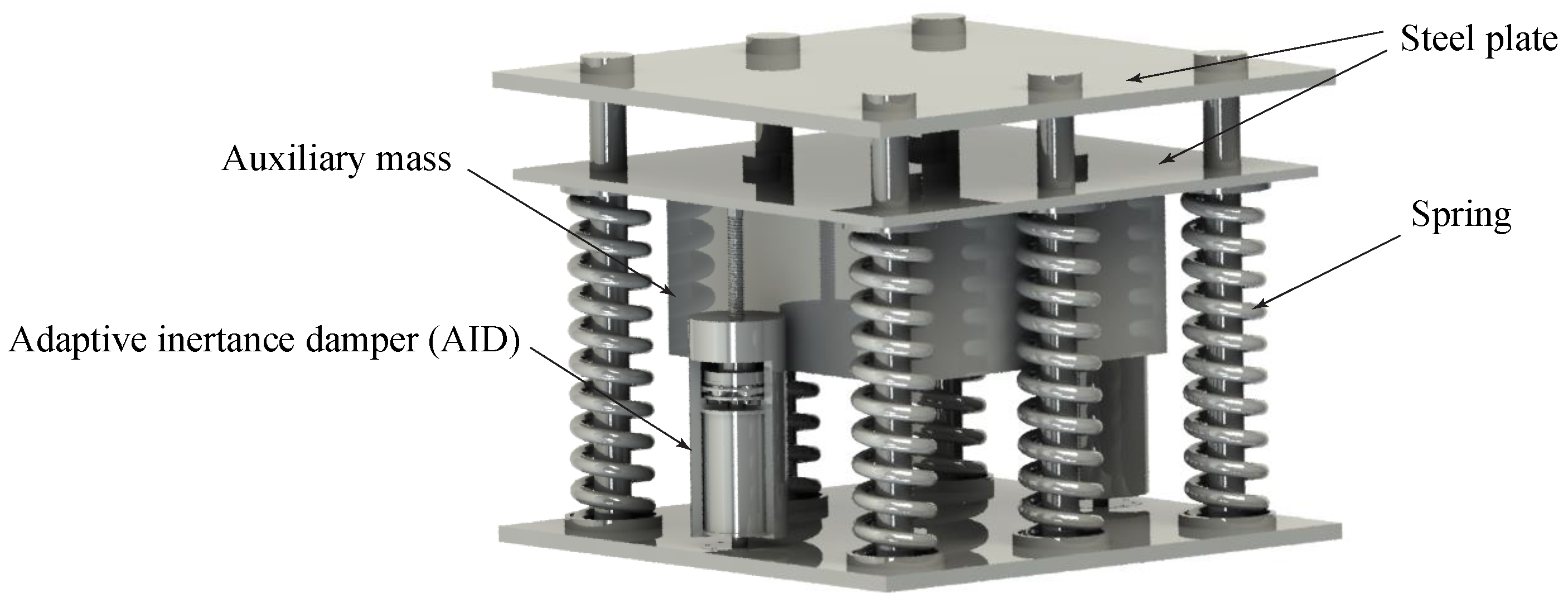
The device construction and main components of the ATMID are described in this section in addition to its mechanism of action. The considered ATMID, as shown in Figure 1, is fabricated by a parallel layout consisting of a variable inertance, small viscous damping, and stiffness. Later this layout is serially linked into an auxiliary mass. In this device, a terminal is used to affix the parallel constituents to an additional mass while the second terminal is fixed to the structure where the vibration is to be reduced.
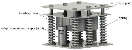
Figure 1.
Perspective view of the adaptive tuned mass inertance damper (ATMID).
The details of the configuration of the proposed variable inertance section called the adaptive inertance damper (AID) are shown in Figure 2. The figure shows a ball-screw inerter and a CVT core such that the outer rotor and ball-screw system are encompassed by the core of the CVT. The conversion of the nut spin to a screw translation, that is, bidirectional movement of the primary structure, occurs due to the interaction between the steel balls and the thread of the screw. The nut’s spinning can be transmitted to the input ring of the CVT via the firm connection between the nut and the input ring (see Figure 2). By tuning the CVT, an ideal rotation can be transmitted and obtained in the output ring. Afterward, the gyration of the output ring is transmitted to the flywheel through the stiff contact between the output ring and the flywheel.
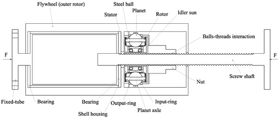
Figure 2.
Symbolic representation and principal components of adaptive inertance damper (AID).
The reciprocating deformation of the structure causes the screw shaft to accelerate translationally. Subsequently, the screw’s acceleration (a) leads the nut to spin, and later the flywheel rapidly swirls by utilizing CVT. The flywheel rotation gives rise to a moment of inertia (I), and afterward an amplified rotational torque. The torque is converted and amplified into a translational inertial force of FI = ba, in the opposite direction to the structure’s motion. The physical light mass of the flywheel (mf) is magnified multiple times, causing the generation of a translational amplified mass known as inertance (b) having kilograms (kg) as its unit. The generated inertance (b) is derived as follows:
where the screw lead is denoted as L, and CVT performs in neutral mode.
Substantially, a large inertial resistance force is provided using the inerter’s magnification mechanism while the physical mass of the flywheel is small. This generated inertial force can be attained in a seamless and variable way as CVT operates in underdrive or overdrive mode. Consequently, a controllable inertance (b) and its associated inertial force are yielded. This will be further described in Section 2.2.
2.2. Continuously Variable Transmission (CVT) Efficiency
The redesigned CVT (Figure 3a) is precisely able to produce a rotary acceleration in the output ring () in a seamless manner. This is because an input angular acceleration occurs in the input ring () due to the primary structure’s deformation. Regarding the configuration of the CVT core, a stator, as well as an idler sun with the same centrality, are surrounded by a casted shell housing as depicted in Figure 3b. In this scheme, the idler sun is capable of rotating and translationally moving relative to the stator. Furthermore, through steel balls enclosed between the idler sun and a rotor with a two-way inward slope on its surface, the rotor can spin relative to the idler. The planets with a planetary arrangement are situated on the surface of the rotor while the shell housing surrounds all the planets. Moreover, two input rings and output rings were positioned in touch with the surfaces of the planets in a location where they are visible (see Figure 3a). In addition, a metal appendage was placed around CVT as shown in Figure 3a, which is able to spin by utilizing a motor shaft. This slight spin of the appendage leads the idler sun to linearly move relative to the stator. The idler sun’s translational motion causes all axles of the planets to slant together, therefore, the planets’ angles are adjustable. Consequently, bidirectional spinning of metal appendage causes the CVT ratio to adjust into overdrive () or underdrive () modes, as displayed in Figure 3c. An external battery can also be supplied to the motor shaft. A controller sends a control signal based on the received frequency of the excitation and then the motor begins to operate.
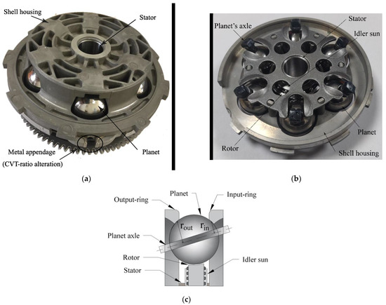
Figure 3.
Core of the continuously variable transmission (CVT): (a) perspective (b) cross section photograph (c) diagrammatic view in overdrive mode.
The ratio between the rotary motion of the flywheel and the screw’s translational motion due to the inter-story drift can be adjusted through the transmission ratio of the CVT (). The CVT core possesses the maximum ratio in the underdrive status () at 0.45 while the ratio in the overdrive status () is 2.2. In the overdrive status, the distance between the surface of the output ring and the planet’s axle is more than that of the input ring (rin < rout). The CVT ratio range (0.45–2.2) can be broadened by modifying the design of the CVT core and its constituents. Therefore, the performance of the AID can be enhanced. Eventually, the operation of the CVT in overdrive or underdrive mode enables the device to attain the variable inertia resistance force. It happens due to the alteration of the CVT ratio within its range (0.45 < < 2.2).
2.3. Analytical Model
The device anatomy, in addition to the assembly of its components, can be modeled by a suitable system with few parametric quantities, showing the dynamic behavior of the device. In the analytical model of the ATMID, the variable inertance (b) links into the small allowable viscous damping coefficient (cd) due to the internal damping of the CVT and the elastic spring (kd) in parallel. Later on, they were serially connected to the attached mass (m). Moreover, in order to express the practical behavior of the ATMID, friction, caused by the interaction between components, is generated. It was taken into consideration in the viscous damping coefficient (cd). It should be pointed out that in this research, the variable inertance could be attained using AID, and later an adaptive TMD with variable inertial force is presented. However, the damping of TMD was obtained from the very small internal damping of the CVT, not viscous oil damping. Nevertheless, a variable inertance integrated with a variable viscous oil damping was introduced through an adaptive viscous inertance damper (AVID) in our previous research [32].
3. Design Concept and Characteristics
Through the accurate adjustment of the CVT ratio () to a proper value along its ratio band, the required output angular acceleration and its associated inertance can be acquired. The variability in the flywheel’s angular acceleration and inertance affects the frequency of the ATMID and its inertial force. Thus, the natural frequency of the ATMID can be seamlessly changed and controlled by using the CVT core. The frequency of the ATMID can be formulated in a simple way in which there ought to be few negligible parameters:
It is well known that the design concept of passive devices comprising an attached mass or an inerter relies on the tuning of their components so as to adjust their frequencies close to that of the structure through the fixed-point theory [47]. Nevertheless, the CVT allows the ATMID calibrates its parameters, resulting in the frequency of the ATMID () to equate to that of the current excitation (). Substantially, the ATMID is capable of adapting its mechanical characteristics such as inertance and frequency based on the detected current force’s frequency. Furthermore, the retuning of the device can be easily implemented using CVT during excitation in addition to the elimination of the detuning effect. In order to demonstrate the alterability in generated inertance by AID, the device is excited by the harmonic displacement of , where the amplitude and frequency of excitation are denoted by and . The proposed AID under harmonic excitation is able to produce the inertial force of . By substituting the acceleration in the equation, the relationship between the displacement and the variable inertial force is given as:
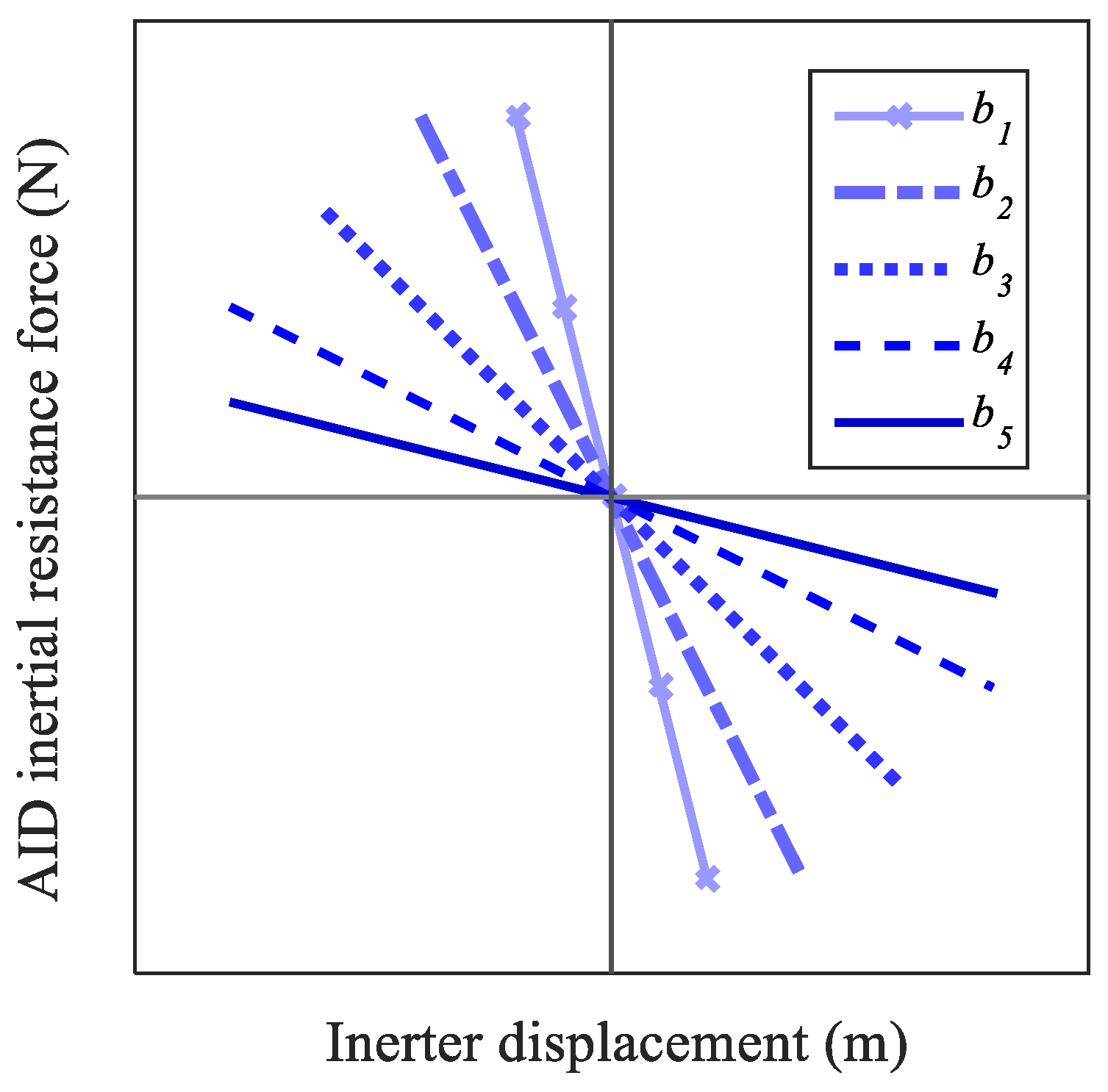
The correlation between the inertial force of the AID and its displacement is shown in Figure 4 in which the gradient of the curve can be altered as the CVT ratio is changed. The slope of the line is the value of the inertance. Through the CVT ratio alteration, a group of the curves with various gradients is provided, showing the variability in inertance (bi) and inertia force generated by the ATMID. In fact, alterations in CVT ratio () are directly proportional to the generated inertance and its associated resistance force. However, there is an inverse relationship between the CVT ratio and the device frequency.
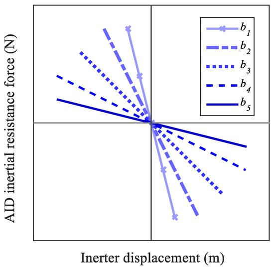
Figure 4.
Force-displacement correlation curve of the proposed AID.
4. Damping Effect of the ATMID for Harmonic Excitation with Various Frequencies
4.1. Model of the ATMID-Controlled SDOF Structure
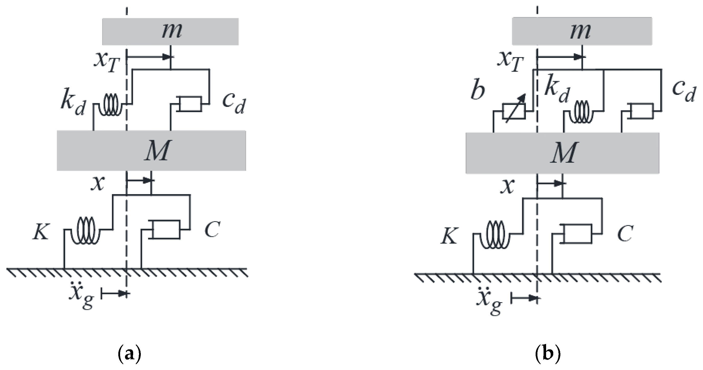
The adaptive TMID-controlled structure was compared with a passive TMD-controlled structure so as to evaluate the damping property of the considered ATMID. The adaptive and passive devices were employed in a single degree of freedom (SDOF) structure induced by harmonic ground excitation as shown in Figure 5. The frequency of the excitation was varied through this research scenario.
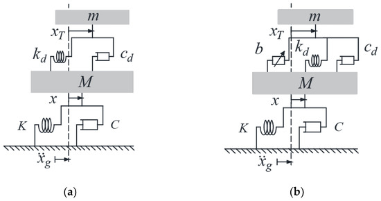
Figure 5.
Model of the SDOF structure incorporated with: (a) passive TMD (b) considered adaptive TMID.
The harmonic ground motion of induces the SDOF structures equipped with passive TMD (PTMD) and adaptive (ATMID) devices. Moreover, the amplitude and frequency of the ground excitation are denoted by (m) and (rad/s), respectively. The governing equation of the motion of the SDOF structure incorporating with the ATMID induced by periodic ground motion is written as follows:
where the notation of the structure’s parameters such as mass, stiffness, and damping coefficient is written as M (kg), K (N/m), and C (N·s/m), respectively. The natural frequency of the structure is given as . The deformation of the auxiliary mass and device components are denoted by and , respectively; where is the deformation of the structure. The governing equations of the system can be transformed into the matrix equation as follows:
The displacement, velocity, and acceleration of the structure induced by the ground acceleration of with the amplitude of are achieved as follows:
The displacement, velocity, and acceleration of the attached mass that was periodically excited are respectively attained as follows:
Also, using little mathematical manipulation in the equations of the system, the output to input ratio (), that is, deformation response of the structure to ground acceleration is written as follows:
According to the current excitation frequency () exerted on the structure, inertance would be altered through the proper calibration of CVT ratio by implementing the ideal tilting in axels of planets. Afterward, the device equates its frequency () to that of the excitation ().
4.2. Simulation of the System
In this part, damping effectiveness and the level of vibration reduction of the proposed ATMID are elucidated. To this end, the passive-controlled, adaptive-controlled, and uncontrolled models were simulated so that the values of the structure’s parameters were consistent with the feasible realization of the experiment as shown in Table 1. Furthermore, the PTMD with its set of parameters of stiffness (kd) and damping (cd) in addition to auxiliary mass (m) was designed based on the fixed-point method as mentioned in Table 2 [47].

Table 1.
Characteristics for the primary structure.
Table 2.
Device parameters for TMD and proposed ATMID.
Regarding the design of the ATMID, as CVT operates in neutral mode () the inertance ratio of b/M = 0.2 and the magnification factor of b/mf = 60 are provided. Nevertheless, in CVT operational modes of overdrive and underdrive, the changeable inertance is obtained (), depending on the range of CVT ratio (0.45–2.2). Likewise, the device stiffness and the range of CVT ratio ought to be set in such a manner that the resonance frequency of the primary structure falls in the ATMID’s frequency range (). The ATMID is able to produce different characteristics of its own (bi,) in each frequency of the excitation () while other parameters are constant. In other words, each set of the device parameters possesses its own specific inertance and frequency at which the device can optimally work in a related excitation frequency.
4.2.1. Results in Domain of the Frequency
The frequency-domain analysis of the structure was conducted to appraise the damping properties of the ATMID as well as its effectiveness on the dynamics of the system. In this manner, the frequency response curve (FRCs) of the PTMD-controlled, ATMID-controlled, and uncontrolled structures were contrasted to specify their dynamic amplification factors (DAFs). We assumed the ratio of the structural deformation () to the acceleration of the ground () to be the dynamic amplification factor (DAF).
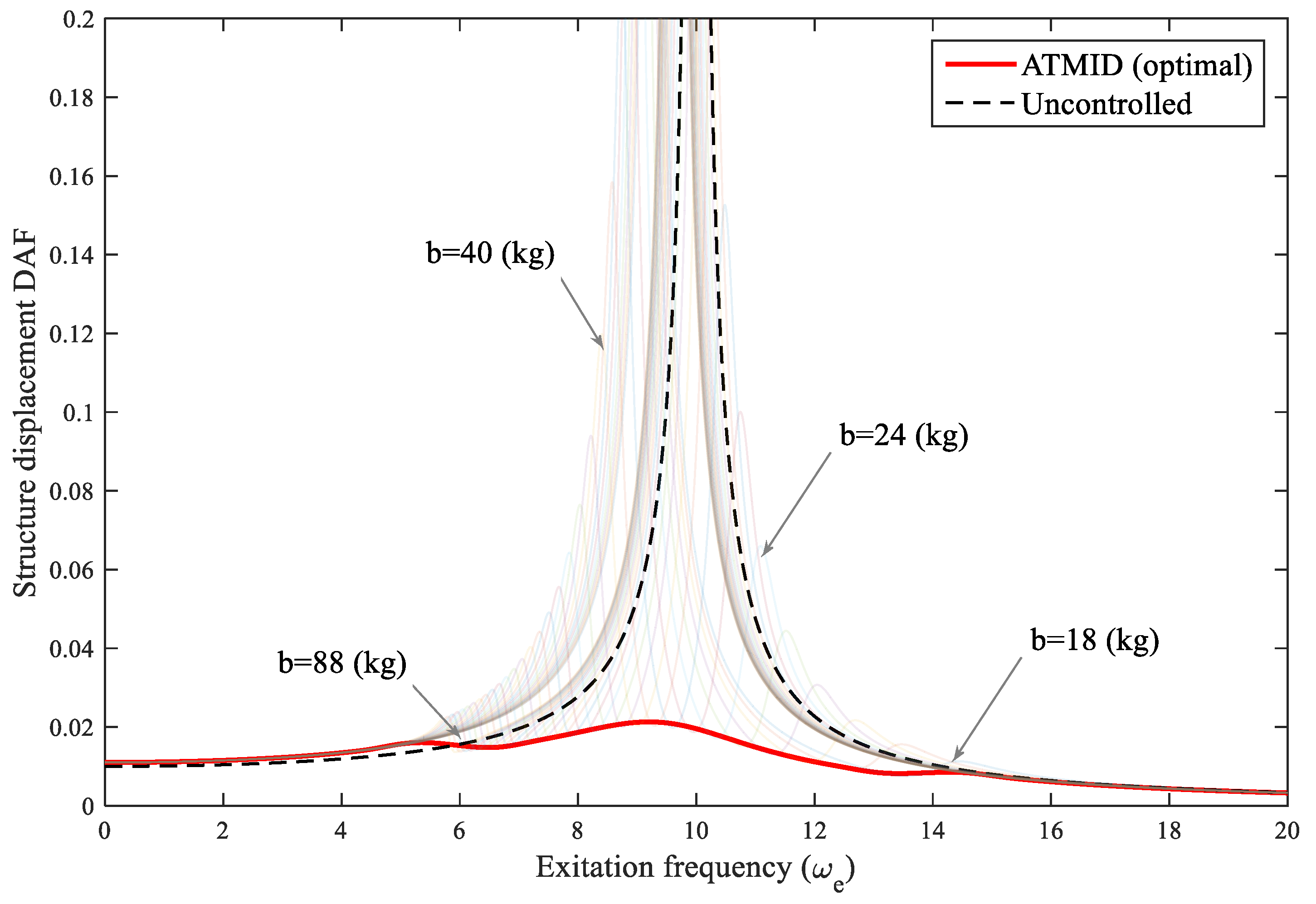
Through the diverse CVT ratio, various sets of inertance (bi) and frequency () can be provided by the ATMID, therefore, a set of diverse curves in the frequency domain is provided as depicted in Figure 6. Each curve possesses its own specifications (bi,) which were achieved by tilting a set of the planets at different angles. In each frequency of the excitation, the minimum DAF is achieved as such that the minimal ordinate is selected between all DAFs curves. Each of the opted minimal DAF is an expression of an ATMID with a particular frequency () at which the topmost DAF reduction occurs in the corresponding force frequency (). The optimal operation of the ATMID was acquired by connecting the entire obtained minimum DAF points in each frequency as referred to in Figure 6. The remarkable damping performance of the ATMID was identified by comparing its optimal curve (red line) with the uncontrolled case (black dashed line).
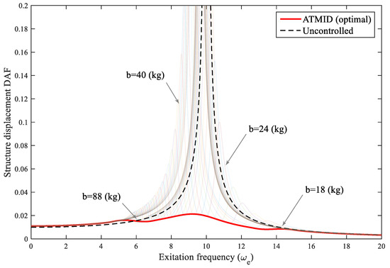
Figure 6.
The FRC of the adaptive controlled and uncontrolled SDOF structures.
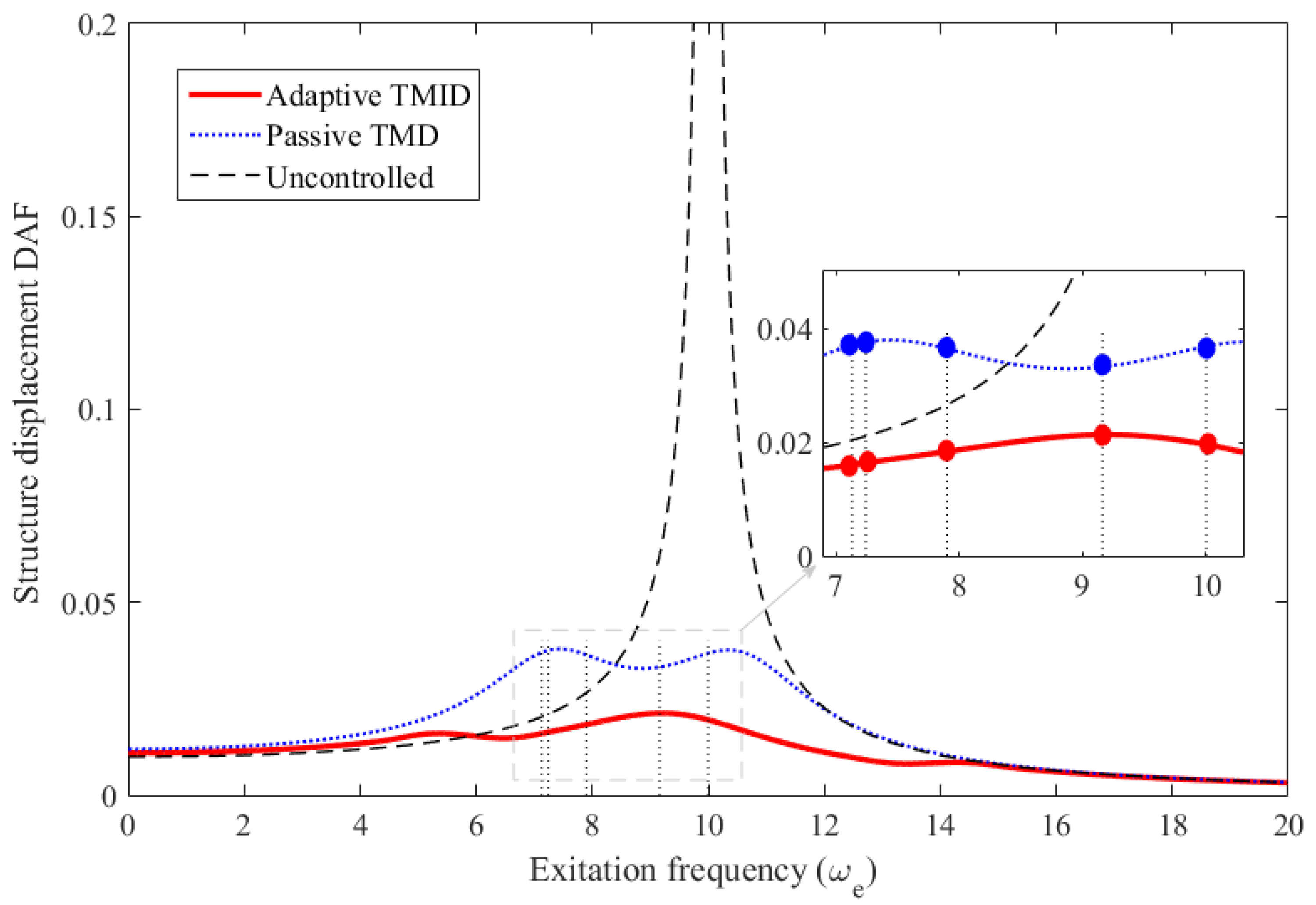
As shown in Figure 7 and summarized in Table 3, the ATMID behaves very well in displacement-DAF suppression in comparison with the PTMD. A significant displacement-DAF reduction was achieved using the devices at the resonance frequency of 10 (rad/s). This reduction in the ATMID with a mass ratio of 0.1 is more than in the PTMD with a mass ratio of 0.2. At the frequency of 9.22 (rad/s) with maximal DAF of the ATMID, the DAF in the ATMID is much less than the PTMD while their generated inertance is 42 (kg). Furthermore, the widest DAF-variation between the PTMD and uncontrolled cases happens at 7.13 (rad/s) where the ordinate of the PTMD is roughly increased by 46% compared to uncontrolled cases. However, in this frequency (7.13), the ATMID’s ordinate is 56% less than that of the PTMD. Furthermore, it is worth noting that the slight disparity between the excitation frequency and the calculated natural frequency of the ATMID (Table 3) is due to the simplification in the formulation of the device frequency, as presented in the former section.
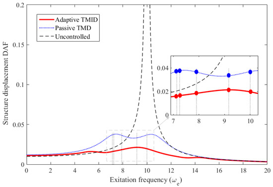
Figure 7.
The FRC of the adaptive-controlled, passive-controlled, and uncontrolled SDOF structures.
Table 3.
Comparison of the uncontrolled, PTMD-controlled, and ATMID-controlled methods.
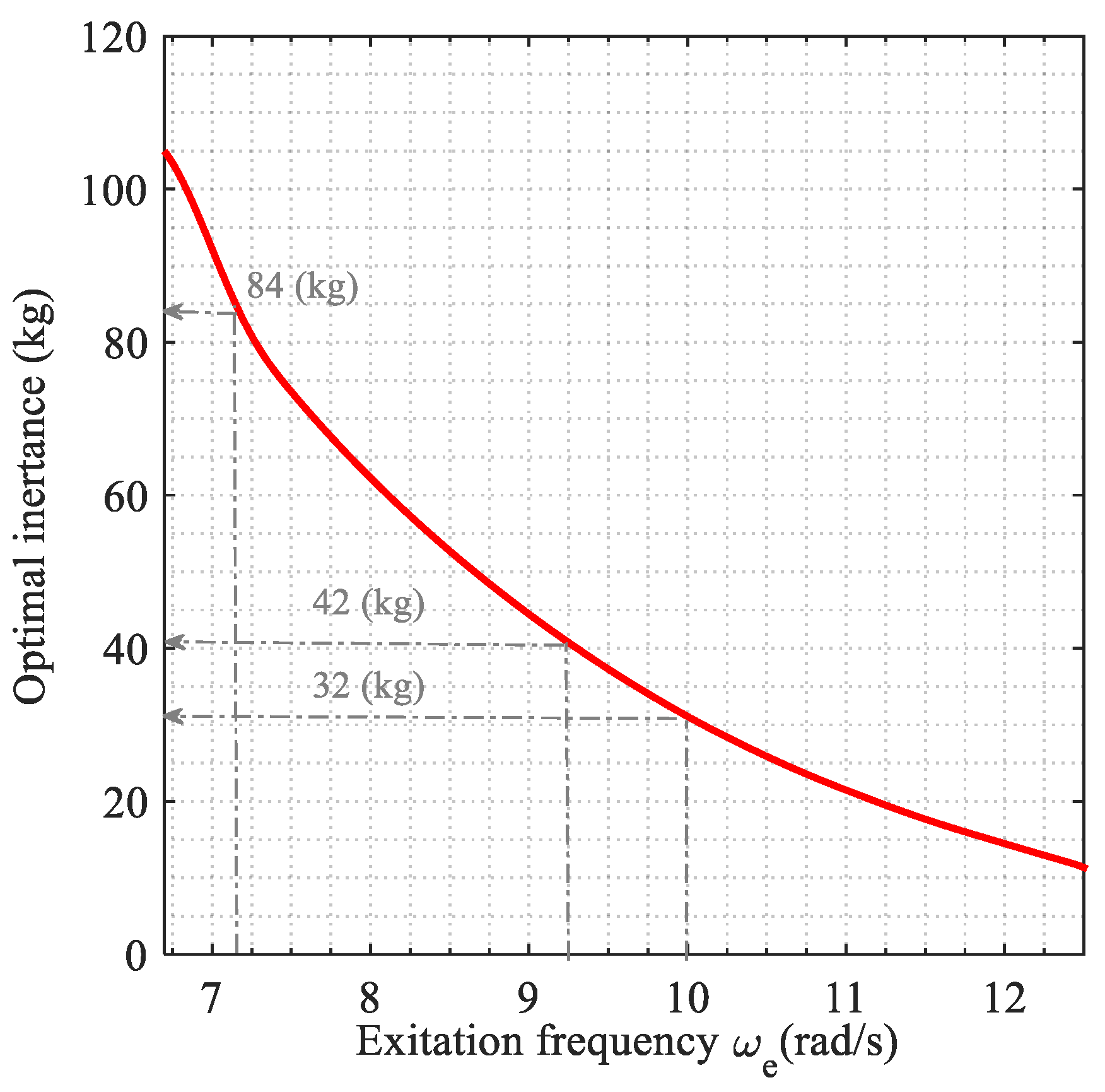
The optimal inertance and its associated device frequency was attained such that the device frequency was adjusted to that of the excitation (). When the excitation with a specific frequency induced the controlled structure, the required optimal inertance was computed as portrayed in Figure 8. It indicates an inverse relationship between the optimum inertance and the relevant frequency. In higher excitation frequencies, the frequency of the ATMID increases when CVT ratio is decreased (low inertance). Although, the ATMID’s frequency is reduced in lower frequencies (high inertance).
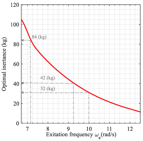
Figure 8.
Required optimal inertance of ATMID in each excitation frequency.
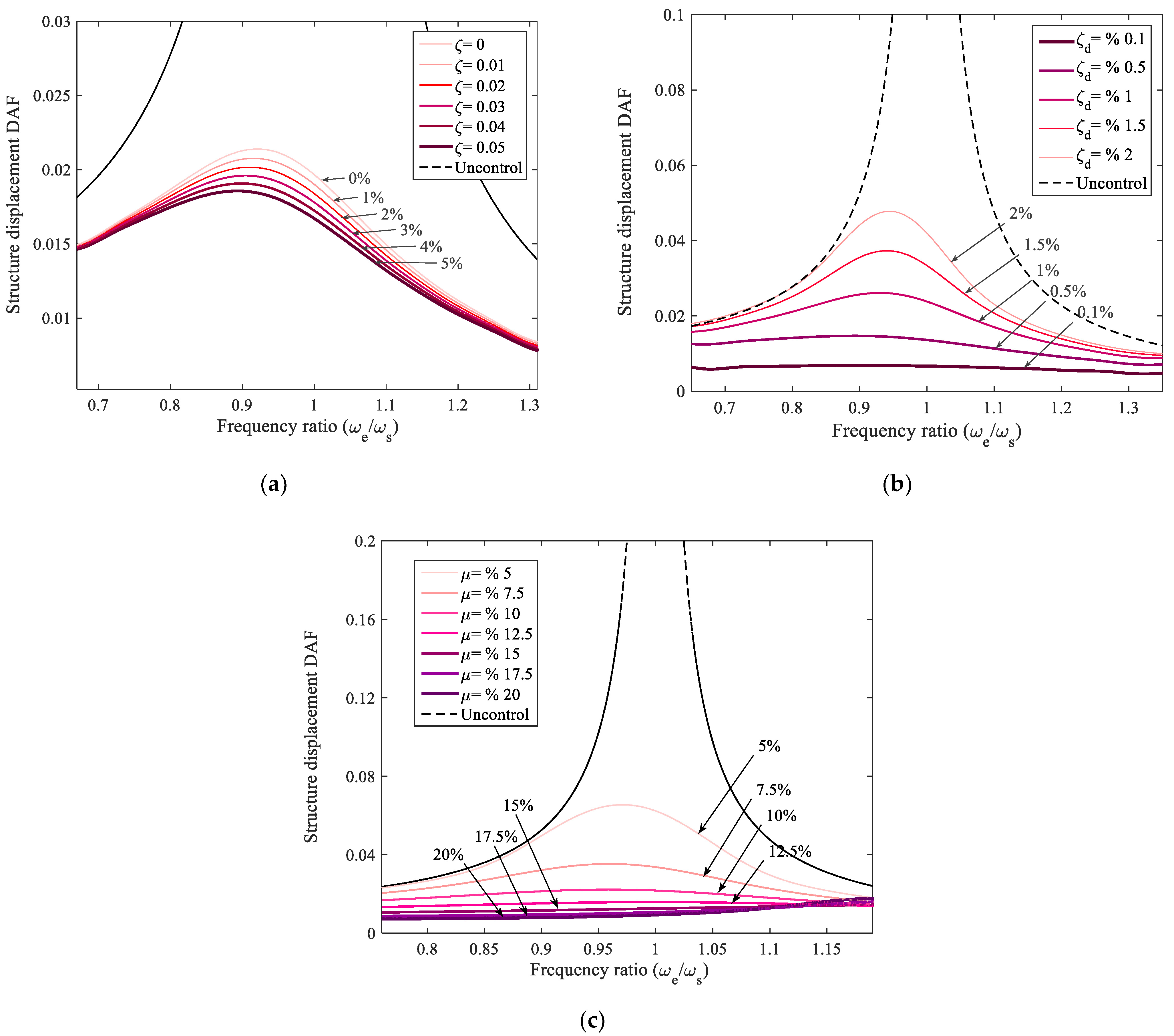
Figure 9a indicates the slight influence of the structural damping coefficient on the damping performance of the ATMID. There is a direct relationship between the structure’s damping and the damping properties of the device. Moreover, the more the device damping coefficient (cd), the higher the ordinate of displacement-DAF, that is, the DAF suppression is diminished (see Figure 9b). The results show that by raising the attached mass (m) of the ATMID, the damping properties are enhanced, that is, higher structural DAF reduction is obtained, as displayed in Figure 9c.
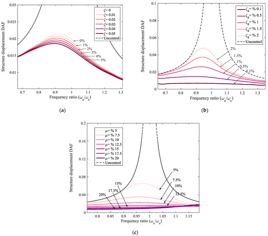
Figure 9.
Damping properties of the ATMID based on: (a) inherent structural damping coefficient, (b) ATMID’s damping coefficient, (c) ATMID’s mass ratio.
It should be pointed out that by introducing a control system, the detection of the force frequency can be eased. Subsequently, the controller sends a signal to the motor, which causes the planet’s axles to slant together, and the angle of the planetary arrangement is adjusted. Later on, the required CVT ratio can be calibrated and the optimal inertance is provided. Afterward, the frequency of the ATMID is tuned to that of the current frequency of excitation, leading to notable damping properties along a vast frequency range.
4.2.2. Time History Analysis
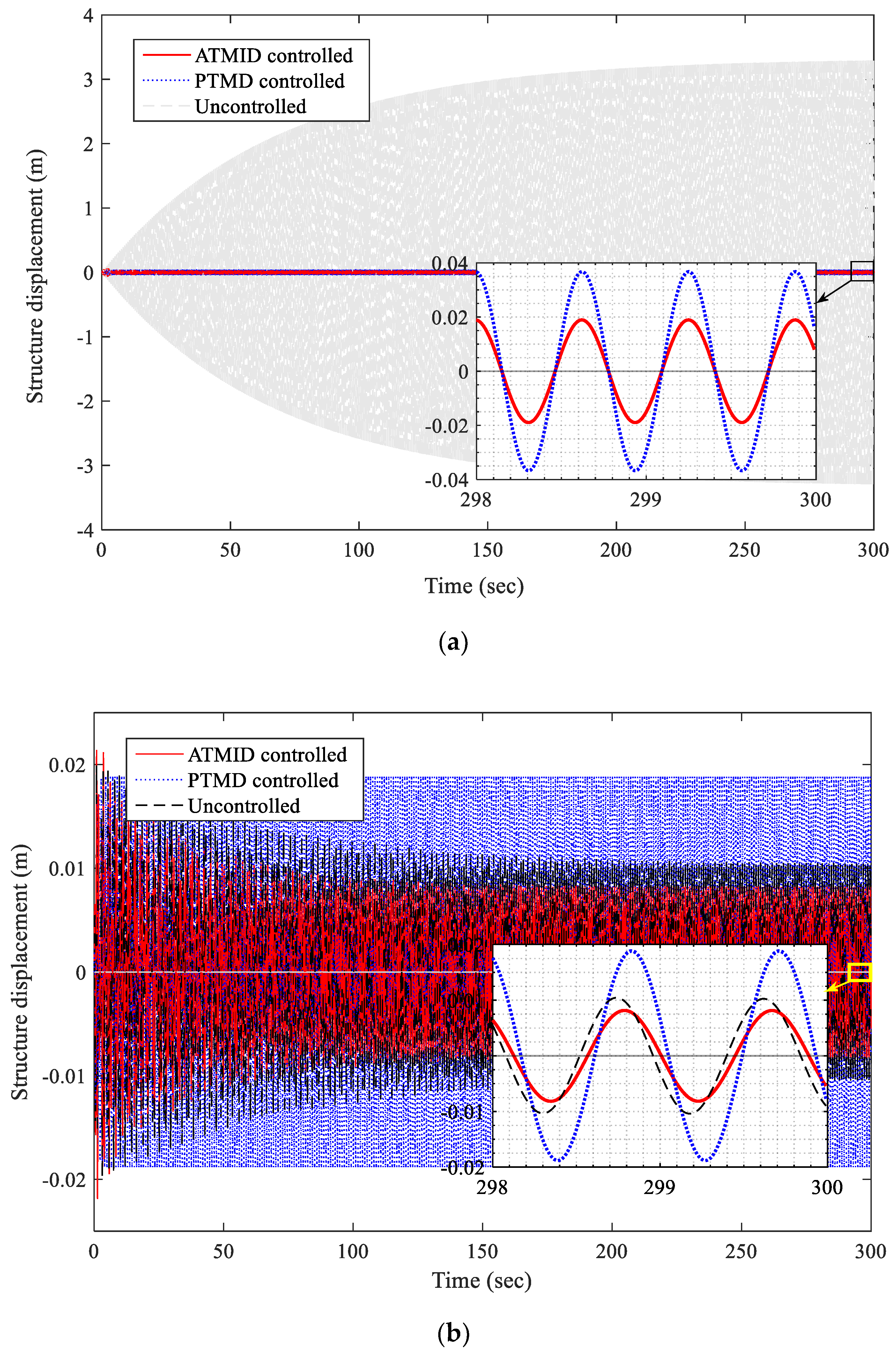
Through the time domain analysis, the displacement of the structure excited by resonance frequency (10 (rad/s)) is shown in Figure 10a. The ATMID and PTMD devices can substantially suppress the vibration of the primary structure in comparison with the uncontrolled resonated structure. The optimal inertance generated by the ATMID is b = 32 (kg) and results in reducing the displacement of the main structure almost twice as much as the PTMD. In a frequency of = 7.13 (rad/s), the PTMD behaves intolerably compared with the uncontrolled case. However, the considered ATMID performs effectively by generating an inertance of b = 84 (kg), as is evident in Figure 10b.

Figure 10.
Structural displacement time-history at: (a) resonance frequency of 10 (rad/s), (b) frequency of 7.13 (rad/s).
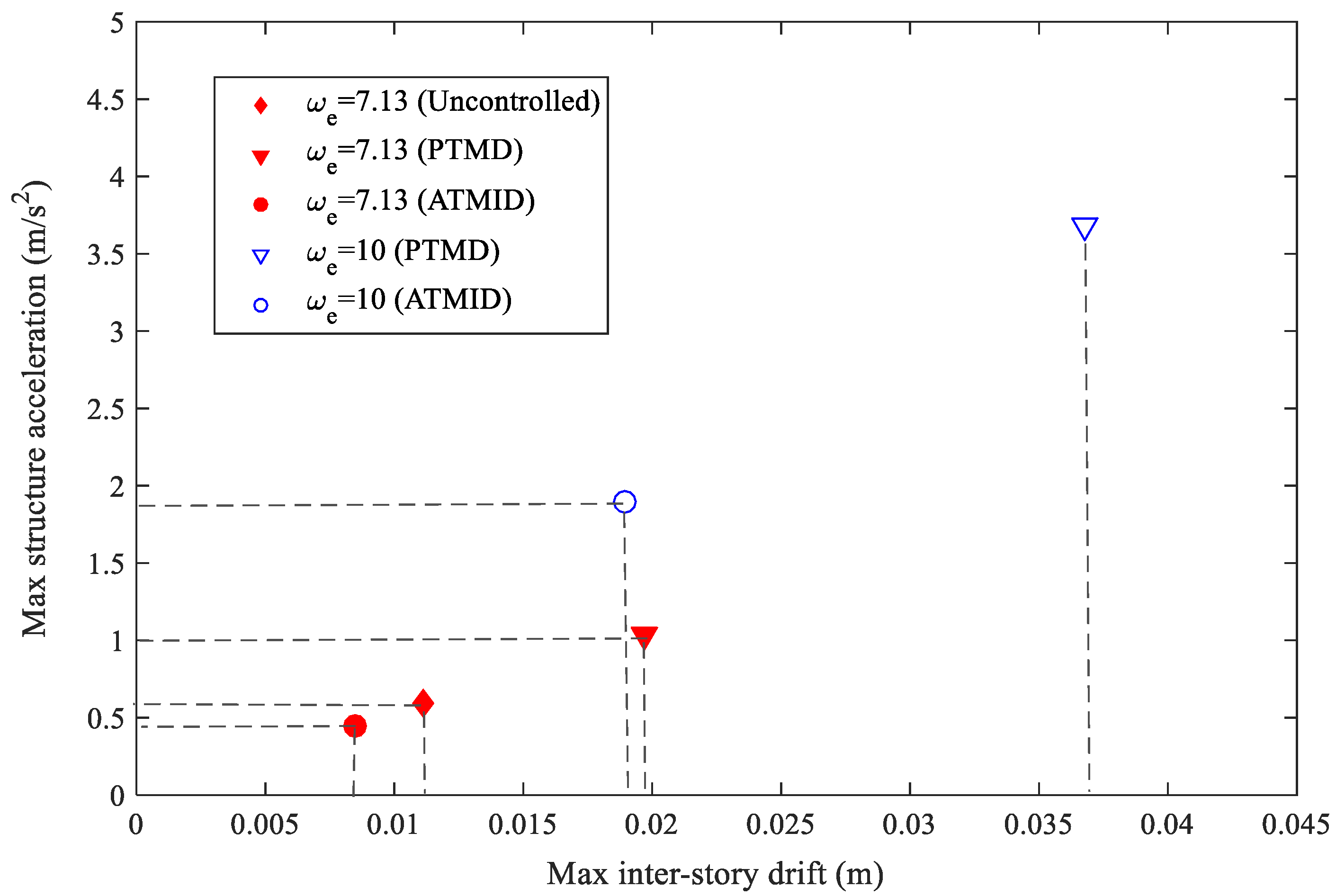
The relationship between the maximum displacement and the maximum acceleration of the main structure for the PTMD, ATMID, and uncontrolled cases in both frequencies is depicted in Figure 11. According to the results, an excellent structural response reduction of the ATMID in contrast with the PTMD is observed. In addition, Table 4 shows the structural displacement denoted by D and its acceleration (denoted by A) for the uncontrolled (U), passively controlled (P), and adaptively controlled (A) structures. In this table, a vibration reduction effect (VRE) is attained for the passive and adaptive control methods compared to the uncontrolled case. For instance, at the frequency of 7.31 (rad/s), the passive TMD is destructive for the structure as it increases the structural displacement by 76% relative to the uncontrolled structure. In contrast, the performance of the ATMID in the reduction of the displacement is superior where it reduces the displacement by 23% relative to the uncontrolled case. The efficiency of both devices is comparable in resonance frequency (10 rad/s).
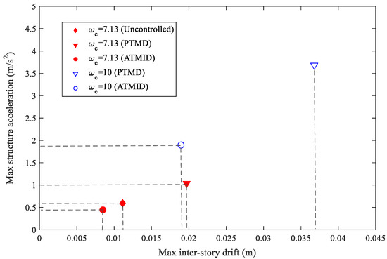
Figure 11.
Structural maximum acceleration-maximum displacement in time-domain analysis at frequencies of 10 and 7.13 (rad/s).
Table 4.
Response structure in uncontrolled (U), PTMD-controlled and ATMID-controlled.
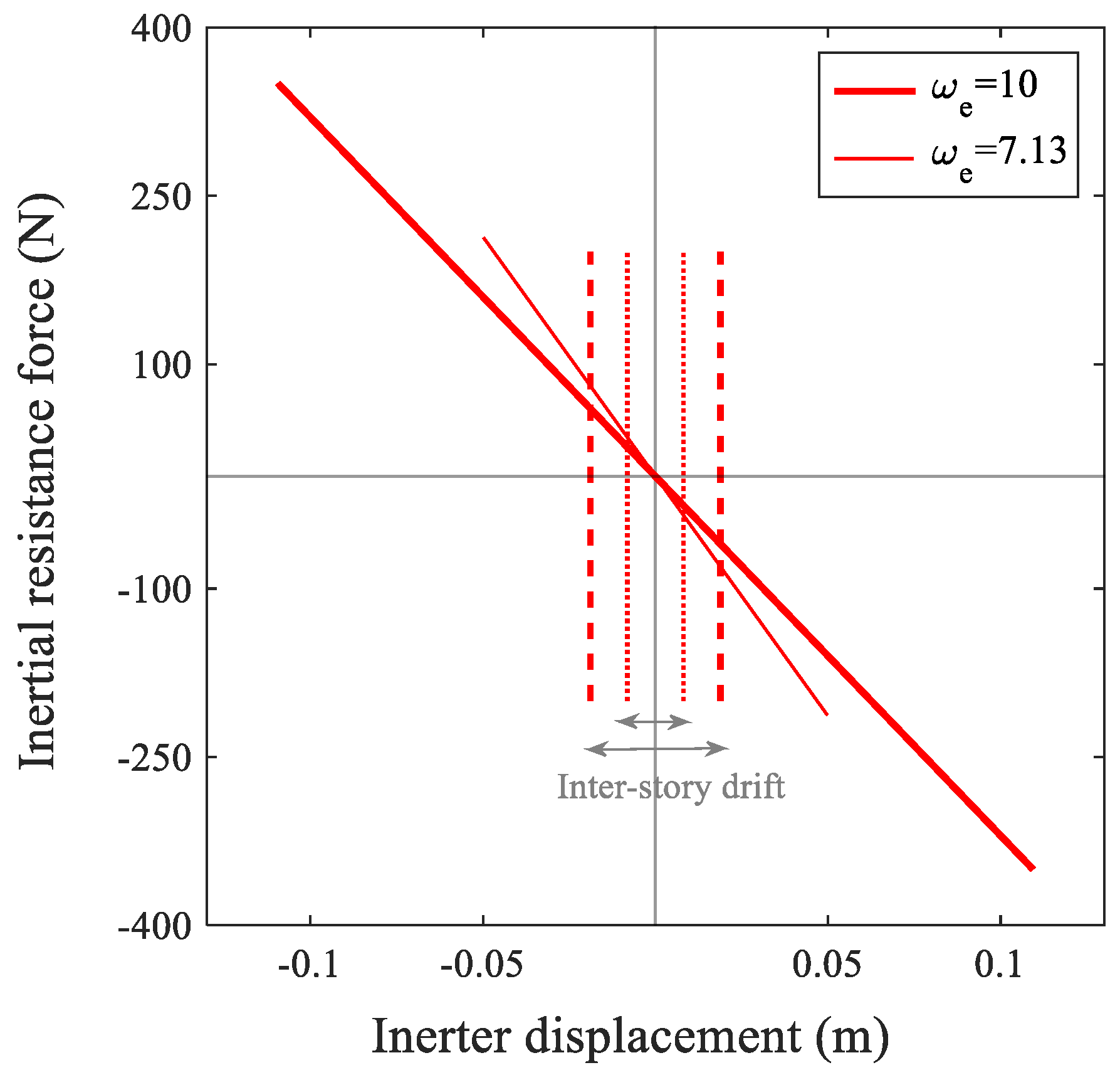
Figure 12 shows the correlation between the inertial force and the displacement produced by the variable inerter of the ATMID. The generated inertance, that is, the gradient of the line in the resonance frequency is less than that of the frequency of 7.13 (rad/s) while its deformation is more than the deformation at the frequency of 7.13 (rad/s). The structural deformation for both cases is represented by dashed lines and dotted symbols for frequencies of 10 and 7.13 (rad/s), respectively, in Figure 12. It is worth noting that the disparity between the two inertances shows the ability of the ATMID to generate different frequencies in various excitation frequencies.
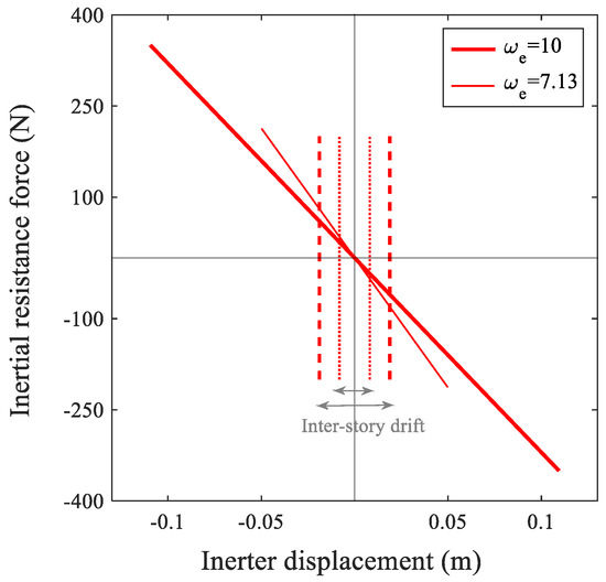
Figure 12.
ATMID inertial force-displacement correlation curve at frequencies of 10 and 7.13 (rad/s).
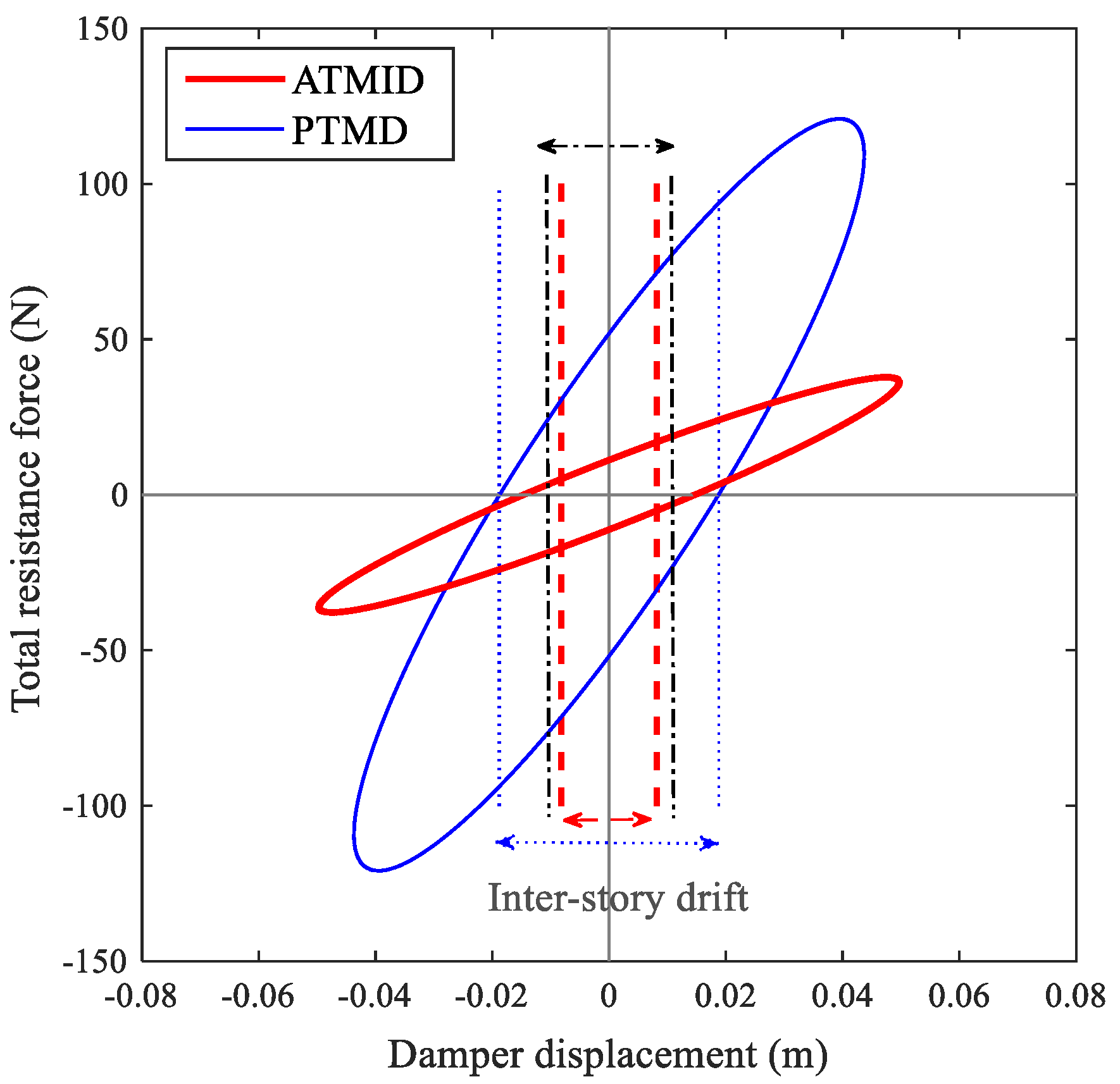
Moreover, the displacement-force curves resulting from the PTMD and ATMID are contrasted in Figure 13 where the structural displacement boundaries are displayed by dashed lines for the ATMID and dotted lines for the PTMD. It is apparent from Figure 13 that substantial reduction in structural displacement is obtained by using the ATMID at the frequency of 7.13 (rad/s), while the displacement of the structure by using the PTMD is more than that of the uncontrolled case as shown by dashed-dotted lines.
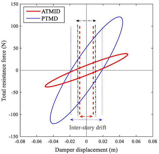
Figure 13.
Total resistant force-displacement curve of PTMD and ATMID at frequency of 7.13 (rad/s).
5. Conclusions
In this research, a newfound vibration reduction device named the ATMID is introduced in which a ball-screw inerter is engaged with a novel redesigned CVT. In the presented CVT with the new configuration and special CVT-inerter assembly, torque transmission happens due to the use of a set of tilting and rotating planets positioned between two rings. The presented ATMID can generate changeable inertance through the seamless controlling of the transmission ratio of the motion of the screw to the gyration of the flywheel. The function of inertance alteration enables the device to produce a smooth variability in its frequency. Therefore, the tuning of the frequency of the ATMID relative to that of the external force can be provided and the device retuning can be eased. By equating the frequency of the ATMID to the frequency of the external excitation, substantial damping properties and vibration mitigation are achieved in an extremely large band of frequency.
The performance of the introduced ATMID in a harmonically induced SDOF structure was also assessed and compared with PTMD-controlled and uncontrolled cases. At the frequency of, for example, 7.13 (rad/s), where the efficiency of the PTMD with a mass ratio of 0.2 is degraded, the ATMID with a mass ratio of 0.1 and various inertances behaves much better. Noticeable oscillation suppression is obtained for the ATMID with a 56% response improvement compared to the PTMD-controlled structure and with 21% when compared to uncontrolled. Results showed that the lesser the damping and higher the mass ratio of ATMID, the higher the damping properties would be. The proposed ATMID with a transmission ratio of 0.45–2.2 offers considerable vibration reduction in an enlarged frequency range in the circumstances that the structure is derived with variable frequency.
Moreover, the concept and capability of the proposed ATMID to achieve the alterable inertance utilizing CVT are demonstrated. The experimental test of the ATMID under seismic and harmonic forces, as well as the investigation of various control algorithms, will be our next research topics. In addition, parametric uncertainty modeling [48], as well as the effect of internal/external noise would be the subjects in our future research. However, expanding the CVT ratio to enhance the device performance would be an attractive challenge.
Author Contributions
Conceptualization, M.A.S. and J.Y.; methodology, M.A.S. and J.Y.; software, M.A.S.; investigation, M.A.S., J.Y., F.W. and X.W.; writing—review and editing, M.A.S., J.Y., F.W. and X.W. All authors have read and agreed to the published version of the manuscript.
Funding
This research was funded by the “National Natural Science Foundation of China, Grant No. 52078293, 51908352” and the “Science Research Plan of Shanghai Municipal Science and Technology Committee, Grant No. 18DZ1205603, 20dz1201301”.
Institutional Review Board Statement
Not applicable.
Informed Consent Statement
Not applicable.
Data Availability Statement
Some or all data, models, or code that support the findings of this study are available from the authors upon reasonable request.
Acknowledgments
We thank Shanghai Jiao Tong University and the Department of Civil Engineering for the use of laboratory equipment and facilities.
Conflicts of Interest
The authors declare no conflict of interest.
References
- Housner, G.W.; Bergman, L.A.; Caughey, T.K.; Chassiakos, A.G.; Claus, R.O.; Masri, S.F.; Skelton, R.E.; Soong, T.T.; Spencer, B.F.; Yao, J.T.P. Structural Control: Past, Present, and Future. J. Eng. Mech. 1997, 123, 897–971. [Google Scholar] [CrossRef]
- Soong, T.; Spencer, B.F., Jr. Supplemental energy dissipation: State-of-the-art and state-of-the-practice. Eng. Struct. 2002, 24, 243–259. [Google Scholar] [CrossRef]
- Casciati, F.; Rodellar, J.; Yildirim, U. Active and semi-active control of structures—Theory and applications: A review of recent advances. J. Intell. Mater. Syst. Struct. 2012, 23, 1181–1195. [Google Scholar] [CrossRef]
- Rahimi, F.; Aghayari, R.; Samali, B. Application of Tuned Mass Dampers for Structural Vibration Control: A State-of-the-art Review. Civ. Eng. J. 2020, 6, 1622–1651. [Google Scholar] [CrossRef]
- Swift, S.J.; Smith, M.C.; Glover, A.R.; Papageorgiou, C.; Gartner, B.; Houghton, N.E. Design and modelling of a fluid inerter. Int. J. Control 2013, 86, 2035–2051. [Google Scholar] [CrossRef]
- De Domenico, D.; Ricciardi, G.; Zhang, R. Optimal design and seismic performance of tuned fluid inerter applied to structures with friction pendulum isolators. Soil Dyn. Earthq. Eng. 2020, 132, 106099. [Google Scholar] [CrossRef]
- Smith, M.C. Synthesis of mechanical networks: The inerter. IEEE Trans. Autom. Control 2003, 47, 1657–1662. [Google Scholar] [CrossRef] [Green Version]
- Zhang, R.; Zhao, Z.; Pan, C.; Ikago, K.; Xue, S. Damping enhancement principle of inerter system. Struct. Control Health Monit. 2020, 27, e2523. [Google Scholar] [CrossRef]
- Alotta, G.; Failla, G. Improved inerter-based vibration absorbers. Int. J. Mech. Sci. 2020, 192, 106087. [Google Scholar] [CrossRef]
- Chen, M.Z.; Papageorgiou, C.; Scheibe, F.; Wang, F.-C.; Smith, M.C. The missing mechanical circuit element. IEEE Circuits Syst. Mag. 2009, 9, 10–26. [Google Scholar] [CrossRef]
- Evangelou, S.; Limebeer, D.J.N.; Sharp, R.S.; Smith, M.C. Mechanical Steering Compensators for High-Performance Motorcycles. J. Appl. Mech. 2006, 74, 332–346. [Google Scholar] [CrossRef]
- Wang, F.-C.; Liao, M.-K.; Liao, B.-H.; Su, W.-J.; Chan, H.-A. The performance improvements of train suspension systems with mechanical networks employing inerters. Veh. Syst. Dyn. 2009, 47, 805–830. [Google Scholar] [CrossRef]
- Wang, F.-C.; Hong, M.-F.; Chen, C.-W. Building suspensions with inerters. Proc. Inst. Mech. Eng. Part C J. Mech. Eng. Sci. 2010, 224, 1605–1616. [Google Scholar] [CrossRef]
- Saitoh, M. On the performance of gyro-mass devices for displacement mitigation in base isolation systems. Struct. Control Health Monit. 2012, 19, 246–259. [Google Scholar] [CrossRef]
- Hessabi, R.M.; Mercan, O. Investigations of the application of gyro-mass dampers with various types of supplemental dampers for vibration control of building structures. Eng. Struct. 2016, 126, 174–186. [Google Scholar] [CrossRef]
- Pradono, M.H.; Iemura, H.; Igarashi, A.; Kalantari, A. Application of angular-mass dampers to base-isolated benchmark building. Struct. Control Health Monit. 2008, 15, 737–745. [Google Scholar] [CrossRef]
- Furuhashi, T.; Ishimaru, S. Mode control seismic design with dynamic mass. In Proceedings of the 14th World Conference on Earthquake Engineering, Beijing, China, 12–17 October 2008. [Google Scholar]
- Hwang, J.-S.; Kim, J.; Kim, Y.-M. Rotational inertia dampers with toggle bracing for vibration control of a building structure. Eng. Struct. 2007, 29, 1201–1208. [Google Scholar] [CrossRef]
- Takewaki, I.; Murakami, S.; Yoshitomi, S.; Tsuji, M. Fundamental mechanism of earthquake response reduction in building structures with inertial dampers. Struct. Control Health Monit. 2012, 19, 590–608. [Google Scholar] [CrossRef]
- Saito, K.; Yogo, K.; Sugimura, Y.; Nakaminami, S.; Park, K. Application of rotary inertia to displacement reduction for vibration control system. In Proceedings of the 13th World Conference on Earthquake Engineering, Vancouver, BC, Canada, 1–6 August 2004. [Google Scholar]
- Arakaki, T.; Kuroda, H.; Arima, F.; Inoue, Y.; Baba, K. Development of seismic devices applied to ball screw: Part 2 Performance test and evaluation of RD-series. J. Archit. Build. Sci. 1999, 5, 265–270. [Google Scholar] [CrossRef] [Green Version]
- Arakaki, T.; Kuroda, H.; Arima, F.; Inoue, Y.; Baba, K. Development of seismic devices applied to ball screw: Part 1 Basic performance test of RD-series. J. Archit. Build. Sci. 1999, 5, 239–244. [Google Scholar] [CrossRef]
- Chen, Z.; Junya, K.; Masahiro, I.; Kohju, I.; Norio, I. Viscoelastically Supported Viscous Mass Damper Incorporated into a Seismic Isolation System. J. Earthq. Tsunami 2016, 10, 1640009. [Google Scholar] [CrossRef]
- Saito, K.; Kurita, S.; Inoue, N. Optimum response control of 1-DOF system using linear viscous damper with inertial mass and its Kelvin-type modeling. J. Struct. Eng. 2007, 53, 53–66. [Google Scholar]
- Ogino, M.; Sumiyama, T. Structural design of a high-rise building using tuned viscous mass dampers installed across three consecutive storeys. In Proceedings of the Twelfth International Conference on Computational Structures Technology, Stirlingshire, UK, 2–5 September 2014. [Google Scholar]
- Ikago, K.; Saito, K.; Inoue, N. Seismic control of single-degree-of-freedom structure using tuned viscous mass damper. Earthq. Eng. Struct. Dyn. 2012, 41, 453–474. [Google Scholar] [CrossRef]
- Kida, H.; Watanabe, Y.; Nakaminami, S.; Tanaka, H.; Sugimura, Y.; Saito, K.; Ikago, K.; Inoue, N. Full-scale dynamic tests of tuned viscous mass damper with force restriction mechanism and its analytical verification. J. Struct. Constr. Eng. Archit. Inst. Jpn. 2011, 76, 1271–1280. [Google Scholar] [CrossRef] [Green Version]
- Kida, H.; Nakaminami, S.; Saito, K.; Ikago, K.; Inoue, N. Verification in analysis model of tuned viscous mass damper based on full-scale dynamic tests. J. Struct. Eng. B 2010, 56, 137–146. [Google Scholar]
- Fujitani, H.; Mukai, Y.; Tomizawa, T.; Hirata, K.; Mazuka, Y.; Fujii, H. Response reduction of base-isolation system against near-fault pulse and long-period ground motions. In Proceedings of the 15th World Conference on Earthquake Engineering, Lisbon, Portugal, 24–28 September 2012. [Google Scholar]
- Sodeyama, H.; Shibata, K.; Sato, Y.; Tomizawa, T.; Fujitani, H. A study on controllable aseismic device with inertia mass and mr fluid. In Proceedings of the ASME 2013 Pressure Vessels and Piping Conference, Paris, France, 14–18 July 2013; p. V008T008A006. [Google Scholar]
- Ji, X.; Cheng, Y.; Hutt, C.M. Seismic response of a tuned viscous mass damper (TVMD) coupled wall system. Eng. Struct. 2020, 225, 111252. [Google Scholar] [CrossRef]
- Sadeghian, M.A.; Yang, J.; Wang, X.-E.; Wang, F. Novel adaptive tuned viscous inertance damper (ATVID) with adjustable inertance and damping for structural vibration control. Structures 2021, 29, 814–822. [Google Scholar] [CrossRef]
- Lu, Z.; Wang, D.; Zhou, Y. Experimental parametric study on wind-induced vibration control of particle tuned mass damper on a benchmark high-rise building. Struct. Des. Tall Spec. Build. 2017, 26, e1359. [Google Scholar] [CrossRef]
- Lu, Z.; Chen, X.; Zhang, D.; Dai, K. Experimental and analytical study on the performance of particle tuned mass dampers under seismic excitation. Earthq. Eng. Struct. Dyn. 2017, 46, 697–714. [Google Scholar] [CrossRef]
- Elias, S.; Matsagar, V. Research developments in vibration control of structures using passive tuned mass dampers. Annu. Rev. Control 2017, 44, 129–156. [Google Scholar] [CrossRef]
- Marian, L.; Giaralis, A. Optimal design of a novel tuned mass-damper–inerter (TMDI) passive vibration control configuration for stochastically support-excited structural systems. Probabilistic Eng. Mech. 2014, 38, 156–164. [Google Scholar] [CrossRef]
- Pietrosanti, D.; De Angelis, M.; Giaralis, A. Experimental study and numerical modeling of nonlinear dynamic response of SDOF system equipped with tuned mass damper inerter (TMDI) tested on shaking table under harmonic excitation. Int. J. Mech. Sci. 2020, 184, 105762. [Google Scholar] [CrossRef]
- Salvi, J.; Giaralis, A. Concept study of a novel energy harvesting-enabled tuned mass-damper-inerter (EH-TMDI) device for vibration control of harmonically-excited structures. J. Phys. Conf. Ser. 2016, 744, 012082. [Google Scholar] [CrossRef] [Green Version]
- Sugiura, K.; Watanabe, Y.; Asai, T.; Araki, Y.; Ikago, K. Experimental characterization and performance improvement evaluation of an electromagnetic transducer utilizing a tuned inerter. J. Vib. Control 2020, 26, 56–72. [Google Scholar] [CrossRef]
- De Domenico, D.; Ricciardi, G. An enhanced base isolation system equipped with optimal tuned mass damper inerter (TMDI). Earthq. Eng. Struct. Dyn. 2018, 47, 1169–1192. [Google Scholar] [CrossRef]
- Gonzalez-Buelga, A.; Lazar, I.F.; Jiang, J.Z.; Neild, S.; Inman, D.J. Assessing the effect of nonlinearities on the performance of a tuned inerter damper. Struct. Control Health Monit. 2017, 24, e1879. [Google Scholar] [CrossRef] [Green Version]
- Javidialesaadi, A.; Wierschem, N.E. Optimal design of rotational inertial double tuned mass dampers under random excitation. Eng. Struct. 2018, 165, 412–421. [Google Scholar] [CrossRef]
- Brzeski, P.; Lazarek, M.; Perlikowski, P. Experimental study of the novel tuned mass damper with inerter which enables changes of inertance. J. Sound Vib. 2017, 404, 47–57. [Google Scholar] [CrossRef]
- Brzeski, P.; Kapitaniak, T.; Perlikowski, P. Novel type of tuned mass damper with inerter which enables changes of inertance. J. Sound Vib. 2015, 349, 56–66. [Google Scholar] [CrossRef]
- Sharma, G.S.; Sarkar, A. Directivity based control of acoustic radiation. Appl. Acoust. 2019, 154, 226–235. [Google Scholar] [CrossRef]
- Sharma, G.S.; Sarkar, A. Directivity-Based Passive Barrier for Local Control of Low-Frequency Noise. J. Theor. Comput. Acoust. 2018, 26, 1850012. [Google Scholar] [CrossRef]
- Den Hartog, J.P. Mechanical Vibrations; Courier Corporation: New York, NY, USA, 1985. [Google Scholar]
- Sharma, G.S.; Faverjon, B.; Dureisseix, D.; Skvortsov, A.; MacGillivray, I.; Audoly, C.; Kessissoglou, N. Acoustic Performance of a Periodically Voided Viscoelastic Medium With Uncertainty in Design Parameters. J. Vib. Acoust. 2020, 142, 061002. [Google Scholar] [CrossRef]


Publisher’s Note: MDPI stays neutral with regard to jurisdictional claims in published maps and institutional affiliations. |
© 2021 by the authors. Licensee MDPI, Basel, Switzerland. This article is an open access article distributed under the terms and conditions of the Creative Commons Attribution (CC BY) license (https://creativecommons.org/licenses/by/4.0/).