
Texture Modification of 3D-Printed Maltitol Candy by Changing Internal Design


Abstract
:1. Introduction
2. Materials and Experimental Setup
2.1. Materials
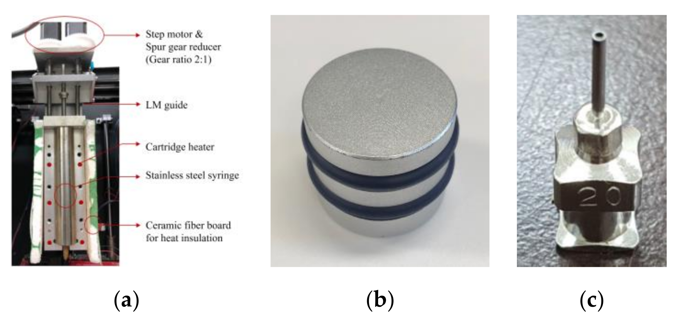
2.2. Material Extruder
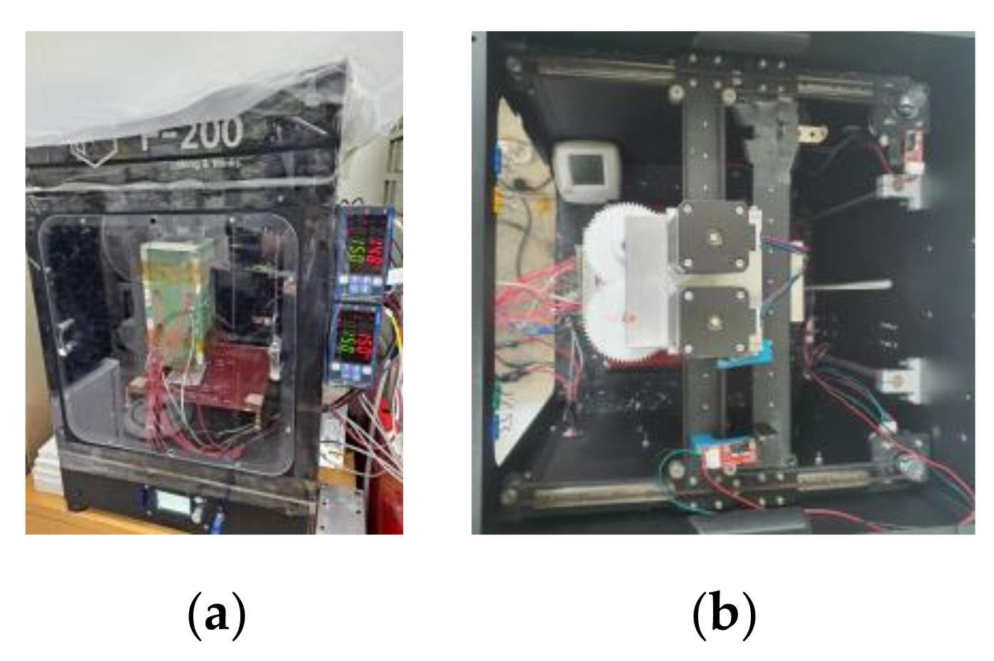
2.3. Experimental Equipment
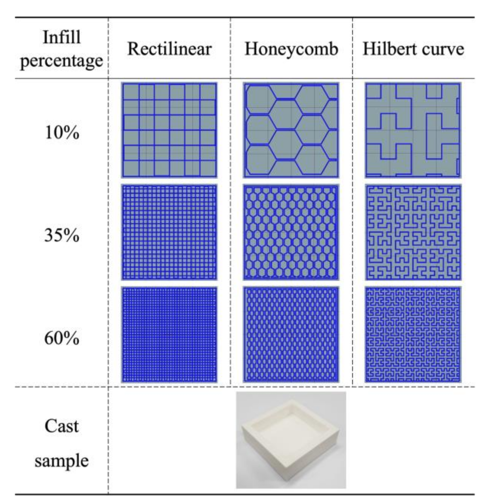
2.4. 3D-Printed Candy
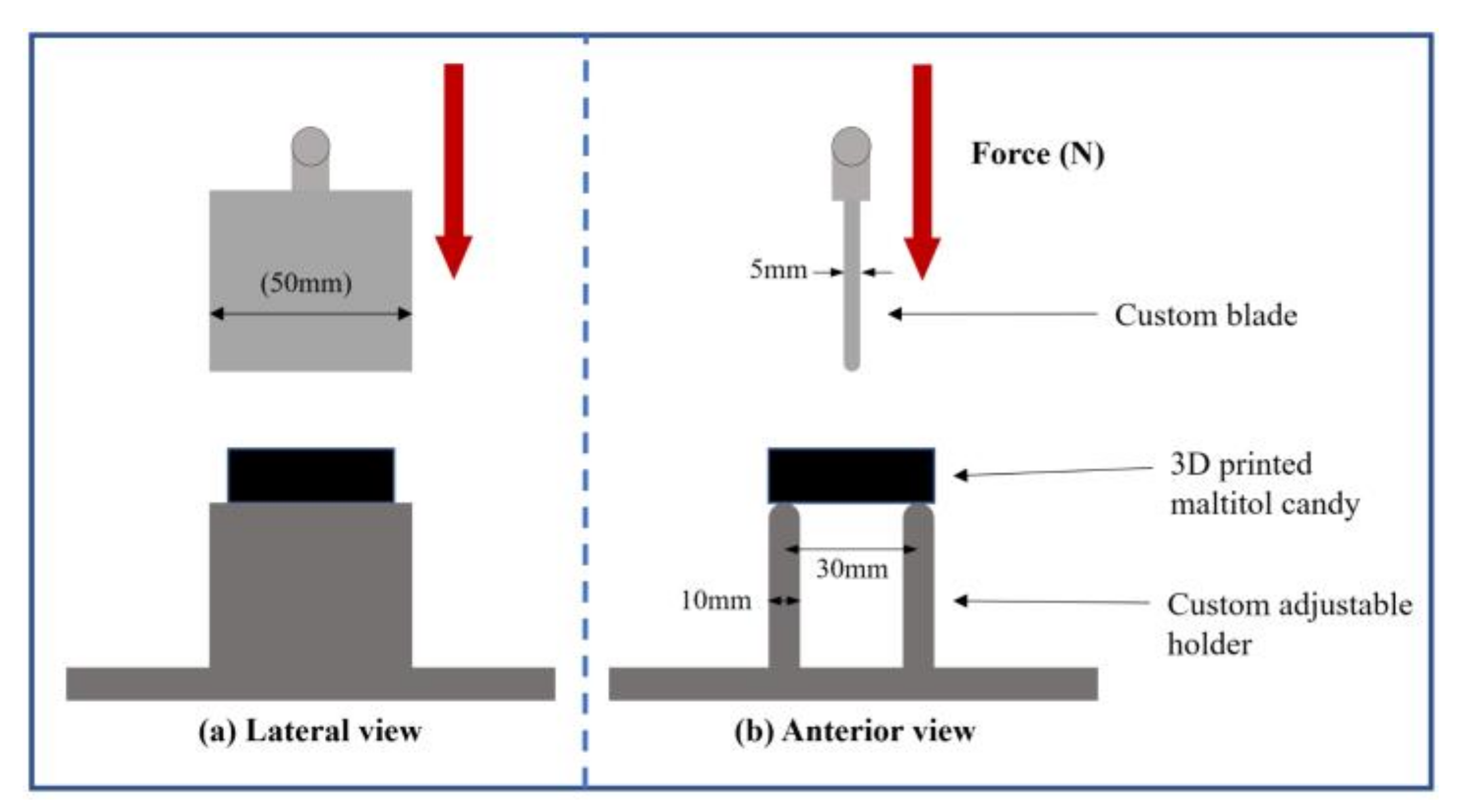
2.5. Textural Testing Method
3. Extrusion Process
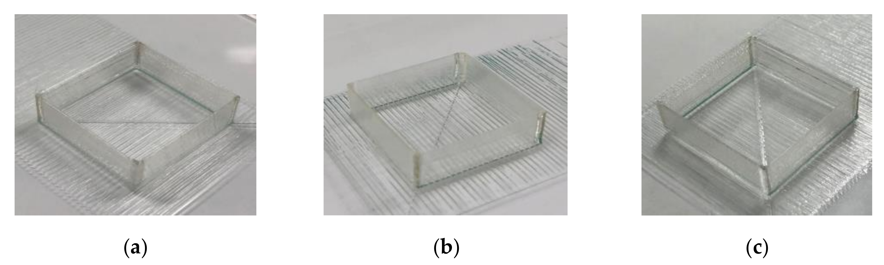
3.1. Extruder Temperature
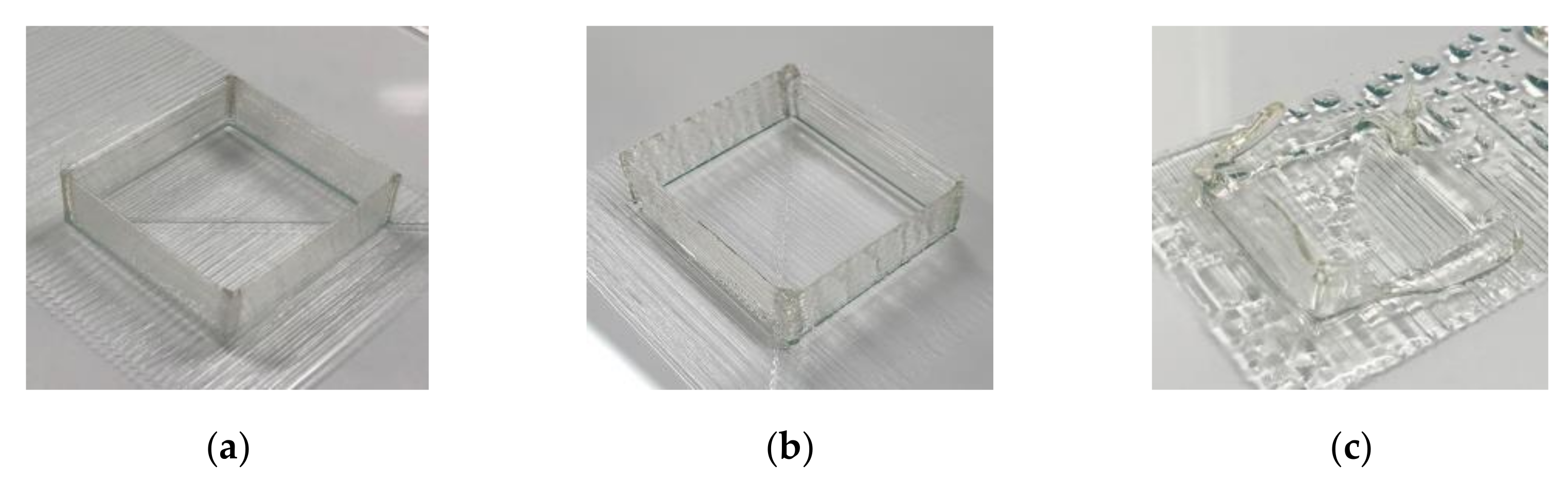
3.2. Chamber Condition
3.2.1. Chamber Temperature
3.2.2. Chamber Humidity
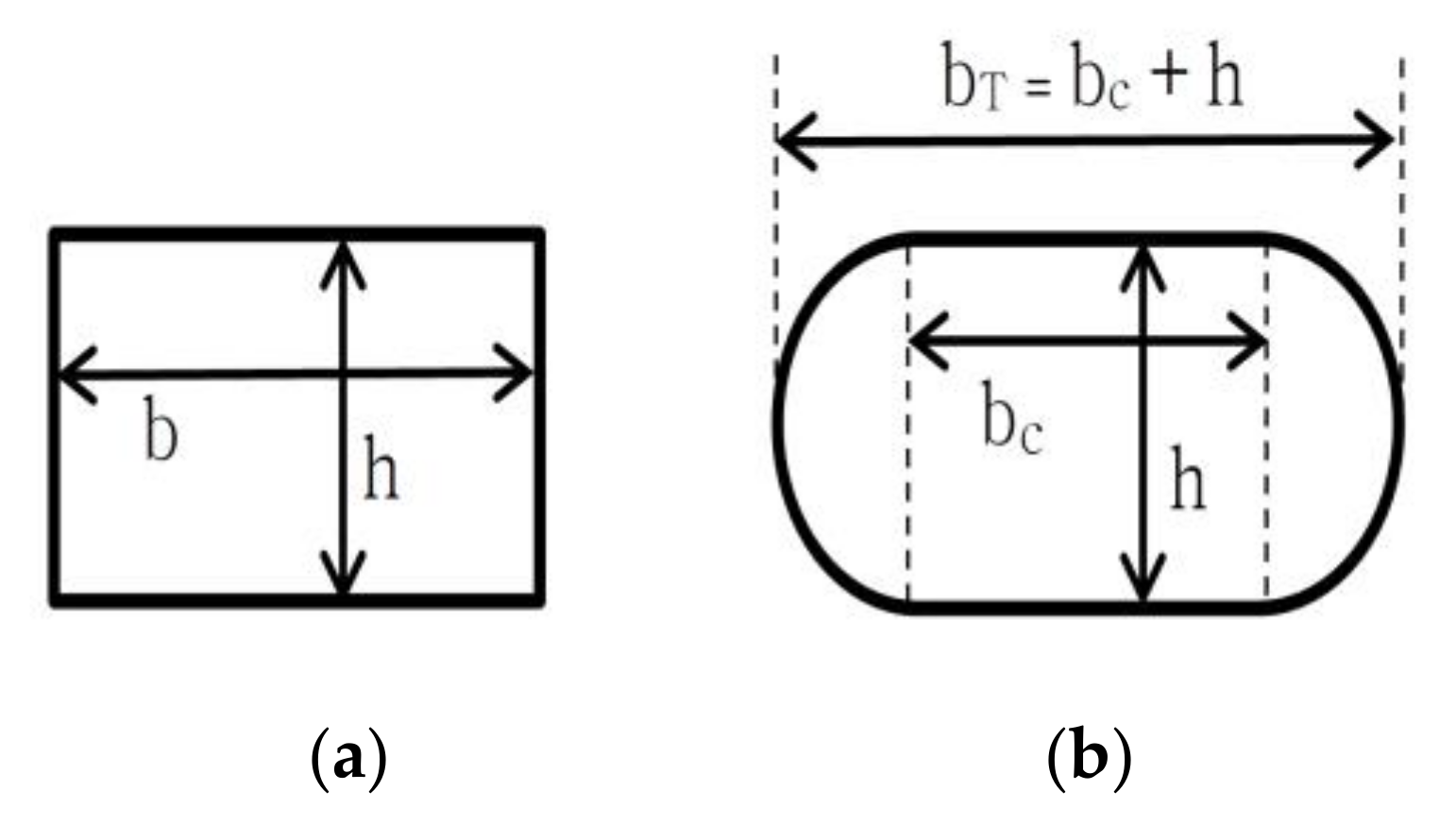
3.3. Syringe Piston Feed Rate
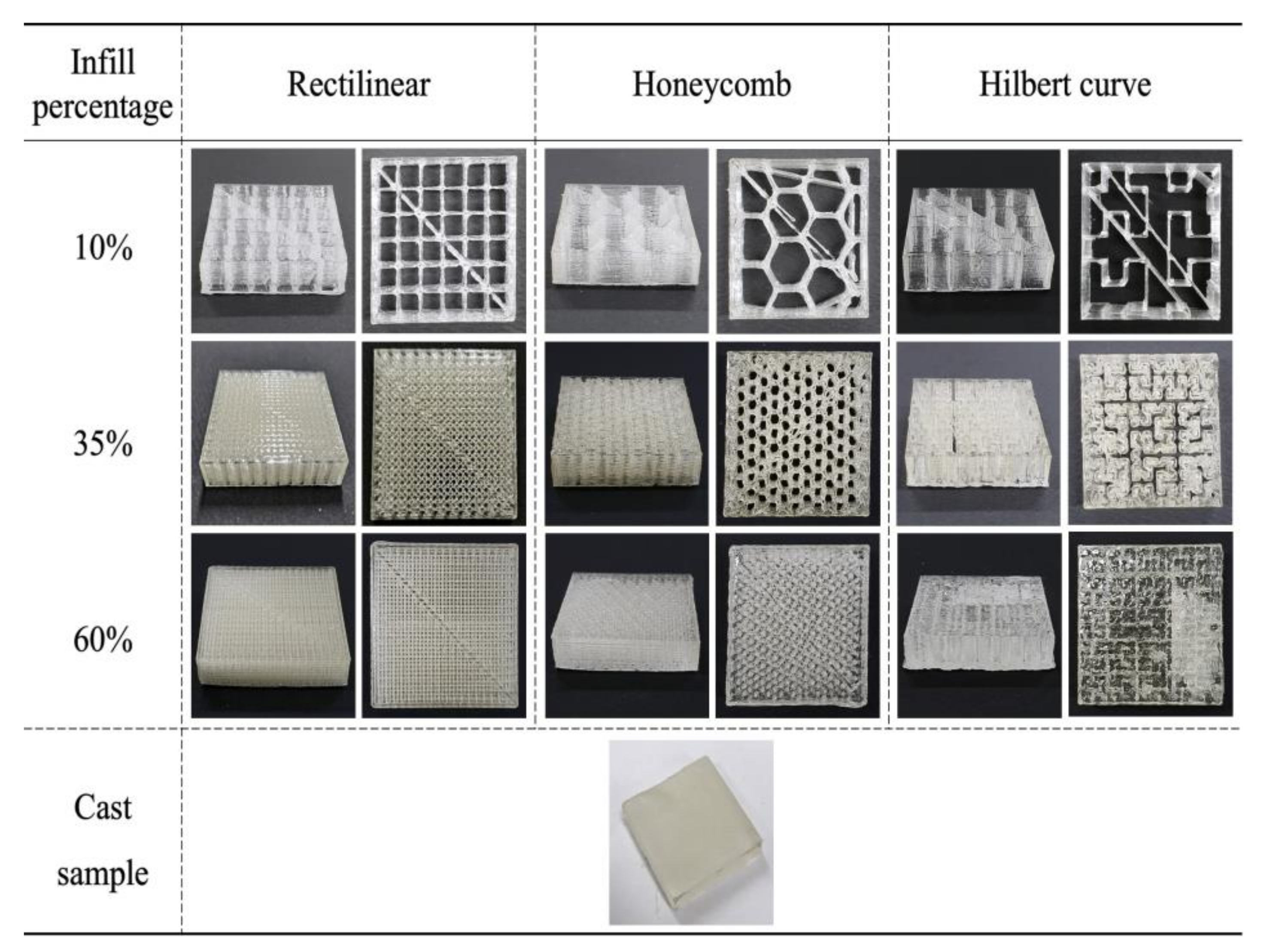
4. Texture Test of 3D-Printed Candy
4.1. Printing Stability of the Selected Process
4.2. Flexural Force of the 3D-Printed Candy
5. Conclusions
Author Contributions
Funding
Institutional Review Board Statement
Informed Consent Statement
Data Availability Statement
Conflicts of Interest
References
- Shin, Y.M. Types and Applications of 3D Printers. Polym. Sci. Technol. 2015, 26, 404–409. [Google Scholar]
- Shin, I.J.; Park, M.S. Direct Conductive Patterning on 3D Printed Structure Using Laser. Phys. Status Solidi Appl. Mater. Sci. 2018, 215, 1700597. [Google Scholar] [CrossRef]
- Hwang, S.R.; Park, M.S. Property analysis of photo-polymerization-type 3d-printed structures based on multi-composite materials. Appl. Sci. 2021, 11, 8545. [Google Scholar] [CrossRef]
- Choi, S.; Park, M. Fabrication of Conductive Patterns on 3D Printed Structure Using Photo-Polymerization Technology. Phys. Status Solidi 2019, 216, 1801017. [Google Scholar] [CrossRef]
- Chu, W.-S.; An, S.-H. Bio Printing. CDE Rev. 2008, 14, 5–11. [Google Scholar]
- Ryu, B.-H.; Choi, Y. The role of functional materials and inkjet printing technology for printable electronics. In Proceedings of the KSME Spring Conference, Daejeon, Korea, 27–30 August 2007; pp. 1925–1929. [Google Scholar]
- He, Y.; Qiu, J.; Fu, J.; Zhang, J.; Ren, Y.; Liu, A. Printing 3D microfluidic chips with a 3D sugar printer. Microfluid. Nanofluid. 2015, 19, 447–456. [Google Scholar] [CrossRef]
- Lipton, J.I.; Cutler, M.; Nigl, F.; Cohen, D.; Lipson, H. Additive manufacturing for the food industry. Trends Food Sci. Technol. 2015, 43, 114–123. [Google Scholar] [CrossRef]
- Van Kjeld, B. 3D Food Printing. Available online: https://www.vo-ho.nl/wp-content/uploads/2014/06/TNO-3D-food-printing-Leeuwarden.pdf (accessed on 24 August 2020).
- Evil Mad Scientist Laboratories CandyFab. Available online: https://candyfab.org/ (accessed on 24 August 2020).
- 3D Systems 3D Culinary Printing. Available online: https://www.3dsystems.com/culinary (accessed on 24 August 2020).
- Alec, B. Pasta Maker Barilla to Show off Its 3D Pasta Printer at the Milan EXPO. 2015. Available online: http://www.3ders.org/articles/20150505-pasta-maker-barilla-to-show-off-its-3d-pasta-printer-at-the-milan-expo-2015.html (accessed on 24 August 2020).
- Hao, L.; Mellor, S.; Seaman, O.; Henderson, J.; Sewell, N.; Sloan, M. Material characterisation and process development for chocolate additive layer manufacturing. Virtual Phys. Prototyp. 2010, 5, 57–64. [Google Scholar] [CrossRef]
- Tan, C.; Toh, W.Y.; Wong, G.; Li, L. Extrusion-based 3D food printing—Materials and machines. Int. J. Bioprinting 2018, 4, 143. [Google Scholar] [CrossRef]
- Karyappa, R.; Hashimoto, M. Chocolate-based Ink Three-dimensional Printing (Ci3DP). Sci. Rep. 2019, 9, 14178. [Google Scholar] [CrossRef]
- Schmitt, M.; Mehta, R.M.; Kim, I.Y. Additive manufacturing infill optimization for automotive 3D-printed ABS components. Rapid Prototyp. J. 2020, 26, 89–99. [Google Scholar] [CrossRef]
- Rocha Pereira, T.; Patterson, A.E.; Messimer, S.L. Buckling Strength of 3-D Printed Thermoplastic Thin Shells: Notes on an Exploratory Study of As-Printed and Reinforced Cases. Appl. Sci. 2020, 10, 5863. [Google Scholar] [CrossRef]
- Alfaify, A.; Saleh, M.; Abdullah, F.M.; Al-Ahmari, A.M. Design for additive manufacturing: A systematic review. Sustainability 2020, 12, 7936. [Google Scholar] [CrossRef]
- Liu, Z.; Bhandari, B.; Prakash, S.; Zhang, M. Creation of internal structure of mashed potato construct by 3D printing and its textural properties. Food Res. Int. 2018, 111, 534–543. [Google Scholar] [CrossRef]
- Mantihal, S.; Prakash, S.; Bhandari, B. Textural modification of 3D printed dark chocolate by varying internal infill structure. Food Res. Int. 2019, 121, 648–657. [Google Scholar] [CrossRef]
- Leung, P.Y.V. Sugar 3D Printing: Additive Manufacturing with Molten Sugar for Investigating Molten Material Fed Printing. 3D Print. Addit. Manuf. 2017, 4, 13–17. [Google Scholar] [CrossRef] [Green Version]
- Bégin-Drolet, A.; Dussault, M.A.; Fernandez, S.A.; Larose-Dutil, J.; Leask, R.L.; Hoesli, C.A.; Ruel, J. Design of a 3D printer head for additive manufacturing of sugar glass for tissue engineering applications. Addit. Manuf. 2017, 15, 29–39. [Google Scholar] [CrossRef]
- Farzin, A.; Miri, A.K.; Sharifi, F.; Faramarzi, N.; Jaberi, A.; Mostafavi, A.; Solorzano, R.; Zhang, Y.S.; Annabi, N.; Khademhosseini, A.; et al. 3D-Printed Sugar-Based Stents Facilitating Vascular Anastomosis. Adv. Healthc. Mater. 2018, 7, e1800702. [Google Scholar] [CrossRef] [Green Version]
- Pollet, A.M.A.O.; Homburg, E.F.G.A.; Cardinaels, R.; den Toonder, J.M.J. 3D sugar printing of networks mimicking the vasculature. Micromachines 2020, 11, 43. [Google Scholar] [CrossRef] [Green Version]
- Hartel, R.W.; Ergun, R.; Vogel, S. Phase/State Transitions of Confectionery Sweeteners: Thermodynamic and Kinetic Aspects. Compr. Rev. Food Sci. Food Saf. 2011, 10, 17–32. [Google Scholar] [CrossRef]
- Roos, Y.; Karel, M. Plasticizing Effect of Water on Thermal Behavior and Crystallization of Amorphous Food Models. J. Food Sci. 1991, 56, 38–43. [Google Scholar] [CrossRef]
- Shimadzu EZ Test Food Texture Analyzer: Creating Culinary Science. Available online: https://www.ssi.shimadzu.com/sites/ssi.shimadzu.com/files/Products/literature/testing/EZ-SX-Brochure-C220-E056.pdf (accessed on 5 March 2020).
- Faivre, A.; Niquet, G.; Maglione, M.; Fornazero, J.; Jal, J.F.; David, L. Dynamics of sorbitol and maltitol over a wide time-temperature range. Eur. Phys. J. B 1999, 10, 277–286. [Google Scholar] [CrossRef]
- Hur, J.-W. Psychological Mechanism and Clinical Implications of Taste Perception: A Literature Review. Korean J. Psychol. Gen. 2017, 36, 189–213. [Google Scholar] [CrossRef]
- Slic3r Manual—Flow Math. Available online: https://manual.slic3r.org/advanced/flow-math (accessed on 30 August 2020).
- RepRap This Is Why You Should Not Adapt Single Perimeter Wall Thickness by Changing the Extrusion/Flow Rate. Available online: https://reprap.org/forum/read.php?1,704450 (accessed on 20 September 2020).
- Lanaro, M.; Forrestal, D.P.; Scheurer, S.; Slinger, D.J.; Liao, S.; Powell, S.K.; Woodruff, M.A. 3D printing complex chocolate objects: Platform design, optimization and evaluation. J. Food Eng. 2017, 215, 13–22. [Google Scholar] [CrossRef]
- Fatimatuzahraa, A.W.; Farahaina, B.; Yusoff, W.A. The effect of employing different raster orientations on the mechanical properties and microstructure of Fused Deposition Modeling parts. In Proceedings of the 2011 IEEE Symposium on Business, Engineering and Industrial Applications (ISBEIA), Langkawi, Malaysia, 25–28 September 2011; pp. 22–27. [Google Scholar]
- Rodriguez, J.F.; Thomas, J.P.; Renaud, J.E. Characterization of the mesostructure of fused-deposition acrylonitrile-butadiene-styrene materials. Rapid Prototyp. J. 2000, 6, 175–186. [Google Scholar] [CrossRef]


| Sugar | Sugar Glass | Maltose | Maltitol | |
|---|---|---|---|---|
| Raw materials | Sucrose | Sucrose + Water + Syrup | Maltose | Maltitol |
| Color after melting | Brown | Transparent | White | Transparent |
| Photograph at the melting point |  |  |  |  |
| Piston Feed Rate (mm/min) | Microscope Image | Line Width (mm) |
|---|---|---|
| 0.07 | 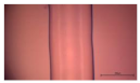 | 0.67 |
| 0.08 | 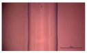 | 0.71 |
| 0.09 | 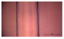 | 0.74 |
| Parameter | Unit | Value |
|---|---|---|
| Nozzle diameter | mm | 0.61 |
| Layer height | mm | 0.2 |
| Printing speed | mm/min | 300 |
| Extruder temperature | °C | 150 |
| Chamber temperature | °C | 26 |
| Chamber humidity | % | 20 |
| Piston feed rate | mm/min | 0.08 |
| Infill Percentage | 10% | 35% | 60% | ||||||
|---|---|---|---|---|---|---|---|---|---|
| Infill Pattern | REL | HNY | HC | REL | HNY | HC | REL | HNY | HC |
| Horizontal (mm) | 39.96 | 39.63 | 40.32 | 40.02 | 39.4 | 39.71 | 39.13 | 39.88 | 40.32 |
| Vertical (mm) | 39.49 | 40.38 | 39.72 | 38.99 | 40.0 | 40.26 | 40.49 | 40.36 | 39.81 |
| Height (mm) | 9.39 | 9.81 | 9.82 | 9.50 | 9.7 | 10.03 | 9.53 | 9.73 | 9.58 |
| Weight (g) | 5.2 | 6.9 | 4.8 | 12.6 | 14.5 | 11.5 | 19.8 | 20.06 | 20.2 |
| Void fraction (%) | 74.66 | 68.29 | 77.98 | 38.68 | 31.57 | 48.26 | 5.40 | 5.34 | 5.24 |
| Infill Percentage | Rectilinear (N) | Honeycomb (N) | Hilbert Curve (N) |
|---|---|---|---|
| 10% | 19.25 ± 2.05 | 14.3 ± 0.4 | 13.55 ± 0.35 |
| 35% | 137.95 ± 6.15 | 92.3 ± 2 | 37.25 ± 0.85 |
| 60% | 338.6 ± 7.3 | 292.65 ± 0.55 | 138.3 ± 0.5 |
| Cast sample | 739.7 ± 1.37 |
Publisher’s Note: MDPI stays neutral with regard to jurisdictional claims in published maps and institutional affiliations. |
© 2022 by the authors. Licensee MDPI, Basel, Switzerland. This article is an open access article distributed under the terms and conditions of the Creative Commons Attribution (CC BY) license (https://creativecommons.org/licenses/by/4.0/).
Share and Cite
Kim, G.-I.; Boo, S.-J.; Lim, J.-W.; Chung, J.-K.; Park, M.-S. Texture Modification of 3D-Printed Maltitol Candy by Changing Internal Design. Appl. Sci. 2022, 12, 4189. https://doi.org/10.3390/app12094189
Kim G-I, Boo S-J, Lim J-W, Chung J-K, Park M-S. Texture Modification of 3D-Printed Maltitol Candy by Changing Internal Design. Applied Sciences. 2022; 12(9):4189. https://doi.org/10.3390/app12094189
Chicago/Turabian StyleKim, Ga-In, Seong-Jae Boo, Jang-Wook Lim, Jin-Kyo Chung, and Min-Soo Park. 2022. "Texture Modification of 3D-Printed Maltitol Candy by Changing Internal Design" Applied Sciences 12, no. 9: 4189. https://doi.org/10.3390/app12094189