Article

Static Bearing Capacity Investigation of a Novel Prefabricated Light-Steel Beam–Column Connection

1
School of Civil Engineering and Architecture, Wuhan University of Technology, Wuhan 430070, China
2
Hainan Research Institute, Wuhan University of Technology, Sanya 572000, China
3
The Third Construction Co., Ltd. of China Construction Third Engineering Bureau, Wuhan 443000, China
4
Zhongshan Institute of Advanced Engineering Technology, Wuhan University of Technology, Zhongshan 528400, China
*
Author to whom correspondence should be addressed.
Appl. Sci. 2022, 12(9), 4387; https://doi.org/10.3390/app12094387
Submission received: 20 March 2022 / Revised: 21 April 2022 / Accepted: 25 April 2022 / Published: 26 April 2022
(This article belongs to the Topic Advances on Structural Engineering)

Abstract

:
In this study, a novel prefabricated light-steel beam–column connection consisting of a thin-walled rectangular hollow section column and two cold-formed steel truss beams is proposed and investigated by carrying out experimental tests. Eight cruciform beam–column connection specimens with different configurations are fabricated and tested to failure under monotonic static loading. First, failure mode and the loading–displacement curve of each specimen are investigated. Consequently, the effect of three variables, including truss-beam configuration, truss-beam type, and with or without sleeve tube reinforcing the column, on the static bearing capacity of the proposed connection and the deflection of the truss beams are investigated. It is found that plug welding the sleeve to the column can significantly increase the static bearing capacity of the proposed connection. In addition, fillet welding connecting the column and the channel connectors to accommodate the end of the truss beams is crucial to the static bearing capacity of the proposed beam–column connection. Because beam–column connections with single-truss beams have a higher load-bearing capacity and require less material and assembly work, it is recommended to adopt this type of configuration for the proposed connection.

1. Introduction

Light-steel structures have been frequently adopted for residential and farm buildings in China due to their many advantages, including faster construction, good strength-to-cost ratio, high strength-to-weight ratio, no wet operation required on site, and large space available. Connections between different thin-walled members are crucial for a light-steel structure. Conventionally, connections using bolts, rivets, screws, and nails are preferred over welding for light-steel structures. This is because welding flaws, such as welding penetration, are frequently detected in construction sites, and the productivity of site welding is much lower. Many researchers have proposed different types of connections using bolts, rivets, screws, and nails for different light-steel structures and investigated the structural performance, including the load-bearing capacity, failure mode, etc.
Zaharia and Dubina [1] proposed a theoretical model for predicting the stiffness of cold-formed steel (CFS) joints based on testing results of bolted lap connections and truss specimens. Dwae et al. [2] carried out experimental tests on thirteen CFS roof trusses consisting of C sections subjected to point loading at the joint. They also investigated strengthening methods to increase the bearing capacity of CFS roof trusses and recommended an optimal approach. Sabbagh et al. [3] first investigated the structural behavior of a novel CFS beam consisting of two bolted C-channel sections with a curved flange, compared it to the conventional beams with a flat flange, and then investigated the structural behavior of the beam–column connections by carrying out finite element (FE) analyses. The column was composed of four C-channel sections with flat flange. It was concluded that the new CFS beam and the corresponding beam–column connection have a higher ductility compared to the traditional counterparts. Later, Sabbagh et al. [4] conducted experimental tests on six bolted CFS beam–column connections subjected to cyclic loading. The connection was composed of the same column and beam numerically investigated before. In addition, advanced FE analyses considering bolt slip were also carried out to calculate the moment–rotation curves of the beam–column connections. Mathieson et al. [5] proposed a novel connector called the Howick Rivet Connector (HRC) for CFS trusses consisting of channel sections. They first tested a T-shaped lap-joint specimen and then a CFS truss to investigate strength and stiffness. They reported that the HRC connection behaved like the one using bolts. Later, Mathieson et al. [6] tested another twenty-six specimens consisting of different channel sections assembled using HRC connectors. All specimens were tested to failure under four-point bending loading. The effect of several key parameters, such as the number of HRCs, on the structural behavior of the CFS trusses were examined. Henriques et al. [7] investigated the structural performance of a type of light-steel framing panel using screws subjected to lateral loading. First, they investigated the behavior of the screw connection and then the light-steel framing panels by carrying out both experimental tests and FE analyses. Bondok and Salim [8] investigated the energy dissipation capacity and the bearing capacity of a type of CFS roof-truss end connection by carrying out both experimental tests and FE analyses. It was concluded that the screw arrangement patten and the loading direction have a significant effect on the energy dissipation capacity of the roof-truss end connection. Bučmys et al. [9] proposed a “three spring” theoretical model to calculate the moment–rotation curves of bolted CFS beam–column joints, with both the column and the beam consisting of back-to-back C-channel sections. McCrum et al. [10] carried out experimental tests on six CFS portal frame specimens. Monotonic loading was applied to three specimens, and the others were subjected to cyclic loading. Energy dissipation capacities of CFS connections bolted with either perfect-fit tolerance or normal tolerance bolt holes were investigated and compared with each other. Results showed that connection bolted with normal-tolerance bolt holes have a better ductility and energy dissipation capacity. Ye et al. [11] conducted a detailed FE study on the earthquake performance of a type of bolted CFS beam–column joints considering the bolting friction-slip behavior. A beam consisting of double channel sections was connected to a column also composed of two channel sections via a gusset plate using bolts. It was concluded that the CFS beam–column joint can be used in seismic regions when taking the bolting friction-slip mechanism into account. In a separate study, Ye et al. [12] numerically investigated bolt arrangement, cross-sectional shape, thickness of gusset plate, and cross-sectional slenderness on the hysteretic behavior of the bolted CFS beam–column connection mentioned above. Recommendations on optimal parameters were given for designing beam–column connections in seismic regions. Dizdar et al. [13] tested seventeen floor trusses consisting of CFS-lipped channel sections under four-point bending loading. The lipped channel sections were connected using screws and rivets. The effect of several crucial parameters, such as thickness of the lipped channel section, on the strength and the stiffness of the truss specimens was investigated. Natesan and Madhavan [14] investigated the structural performance of a sleeve connection between two CFS channel sections. Thirty-nine specimens were tested to failure under three-point bending loading. In addition, Natesan et al. [15] made a comparison between a three-bolt and the two-bolt web cleat used to connect CFS members by carrying out experimental tests on twenty-six specimens. The effect of the thickness and the aspect ratio of the three-bolt web cleat connector on the bearing capacity of the connection was investigated. Song et al. [16] carried out experimental tests on five CFS truss specimens using self-piercing rivet connections. Then, they conducted an FE study to investigate several crucial parameters, such as rivet number, on the structural behavior of the CFS truss. Finally, a theoretical equation was proposed to predict the flexural stiffness of the CFS truss. In addition, Song et al. [17] carried out a comparative study of floor trusses assembled using self-piercing rivets vs. self-drilling screws. Fahmy et al. [18] investigated the structural performance of CFS connections whereby beams are connected to columns by two different gusset plates and self-drilling screws. Wang et al. [19] investigated the hysteretic behavior of a CFS composite floor subjected to cyclic loading. The composite floor consisted of CFS truss beams and a novel lightweight concrete slab. Chen et al. [20] carried out FE analyses on 648 models of apex bracket of CFS portal frames and proposed design equations to predict the strength of the apex brackets. Wang et al. [21] first carried out experimental tests on eight bolted CFS lap connections. Then they carried out FE analyses on twenty-seven CFS bolted beam–column connections to investigate the moment–rotation curves. Osman et al. [22] carried out an FE study on thin-walled back-to-back double C-channel beams reinforced with steel interconnected parts (SIPs). It was concluded that SIPs can increase the strength, initial stiffness, ductility, and energy dissipation capacity of the CFS beams. SIPs can be easily connected to the CFS beam using bolts. Many authors have carried out research on different connections between thin-walled steel sections and between profiled steel beams and columns; however, research on connections between truss beams and a square hollow section (SHS) column has rarely been conducted or reported.
In a previous study [23], the authors carried out experimental tests on twelve light-steel tubular K joints consisting of square hollow sections connected by patented U-shaped connectors with pre-drilled screw holes fabricated by stamping thin-walled steel sheets. Four types of U-shaped connectors, including three with different pattens of stamping indentation and one without any stamping indentation, were investigated. As a continued study, in this paper, we report the structural performance of eight cruciform light-steel beam–column connection specimens subjected to monotonic static loading. The beam–column connection specimen consists of three components, including truss beams, an SHS column, and channel connectors welded to the column to accommodating the ends of truss beams, as shown in Figure 1. Compared to traditional light-steel frame structures consisting of profiled I-section columns and beams, the proposed structure has three advantages. First, truss beams have a much larger strength-to-weight ratio compared to profiled I-sections beams; secondly, pipes for water supply and electrical cables can easily pass through truss beams; and thirdly, SHS columns have an identical moment of inertia on two main axes. Research on the connection between truss beams and columns has rarely been reported. Therefore, it is necessary to design such a connection and investigate its structural performance. In this study, failure mode and loading–displacement curve of each specimen are investigated. In addition, the effect of three primary variables are investigated., i.e., truss-beam configuration, truss-beam type, and with or without sleeve tube reinforcing the column on the load-bearing capacity of the beam–column connections.

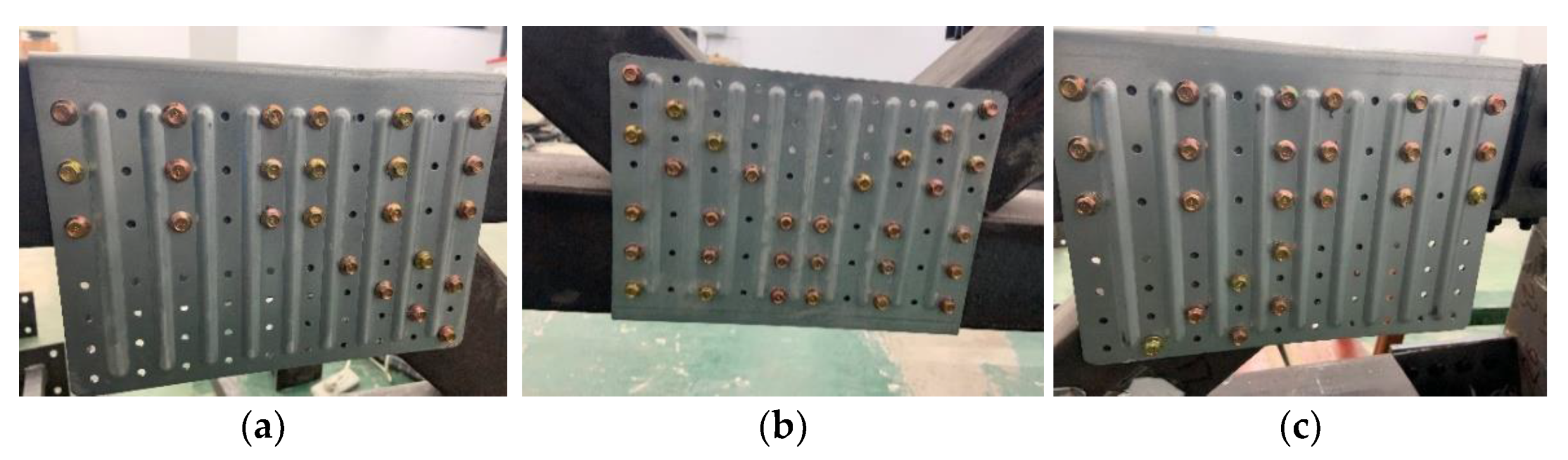
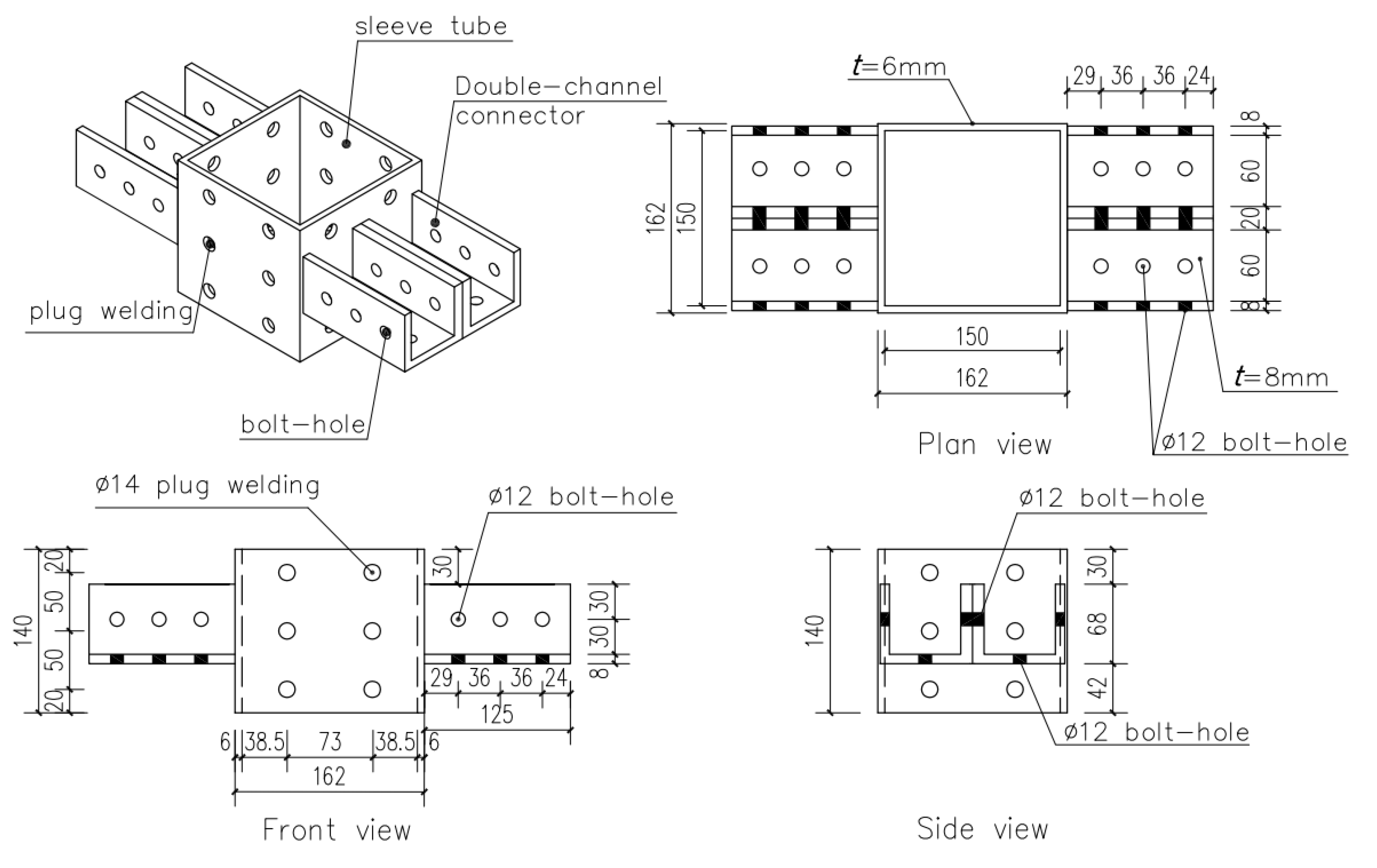
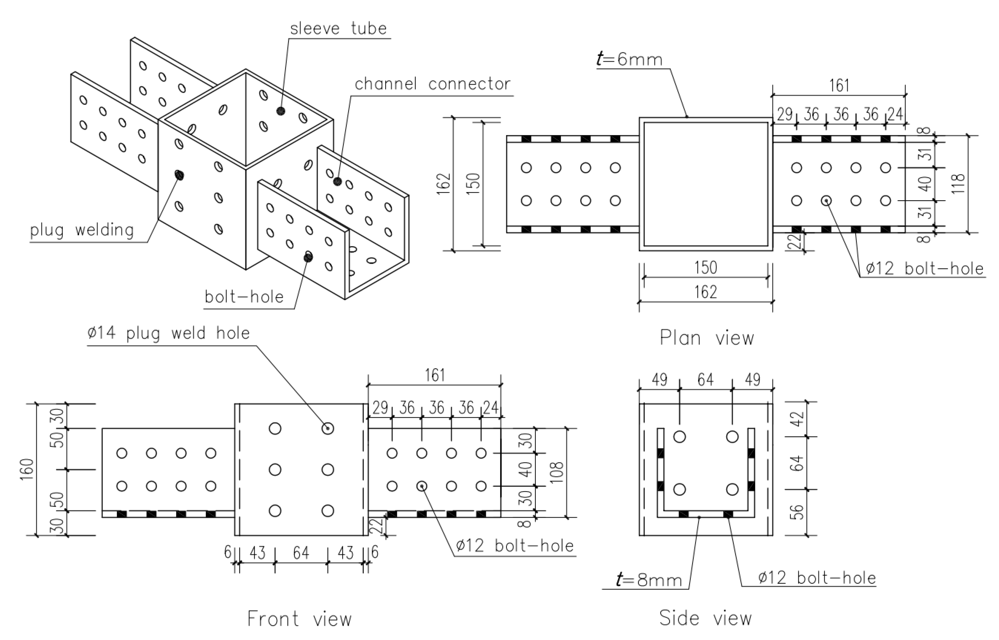
2. Specimen Fabrication

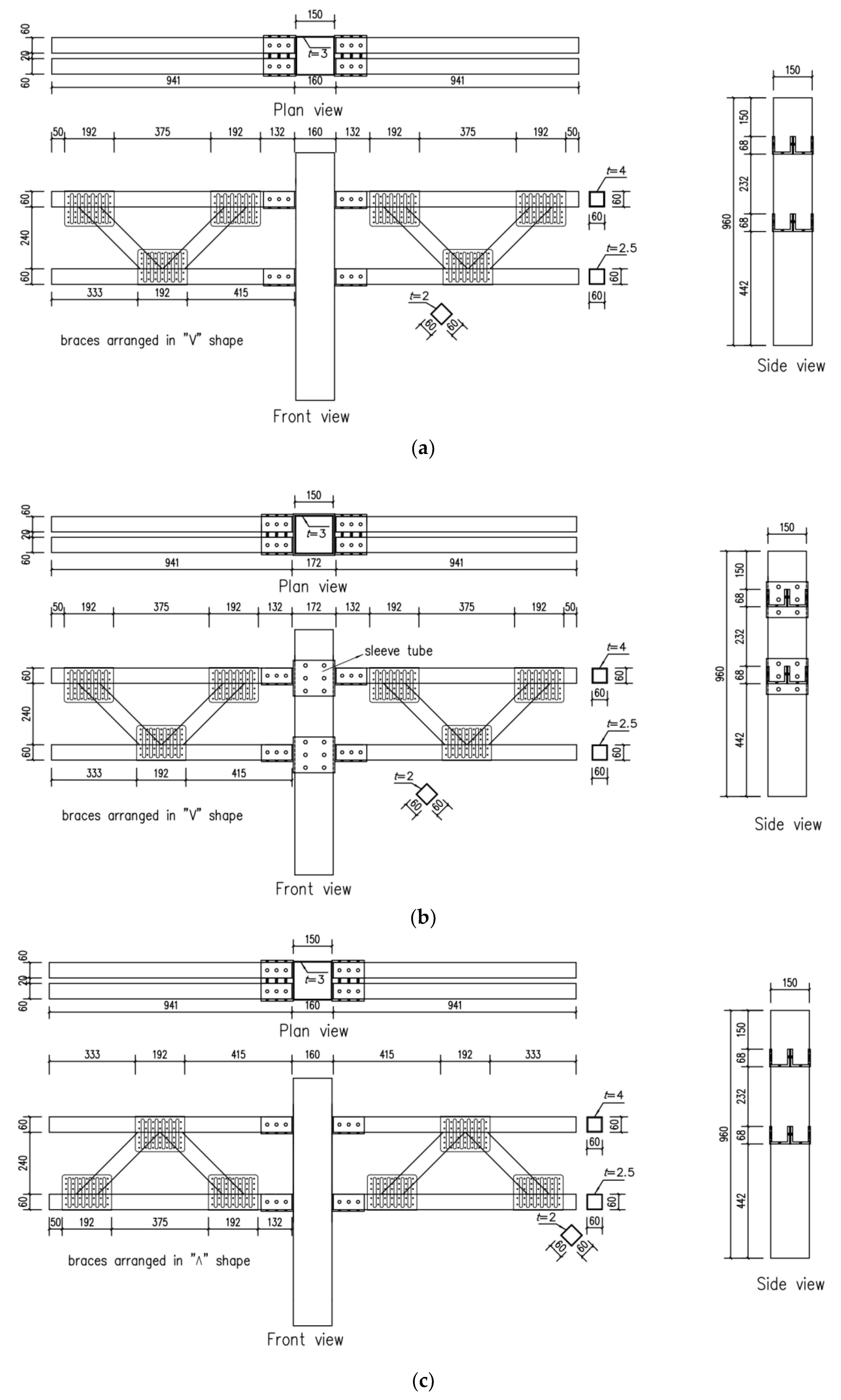
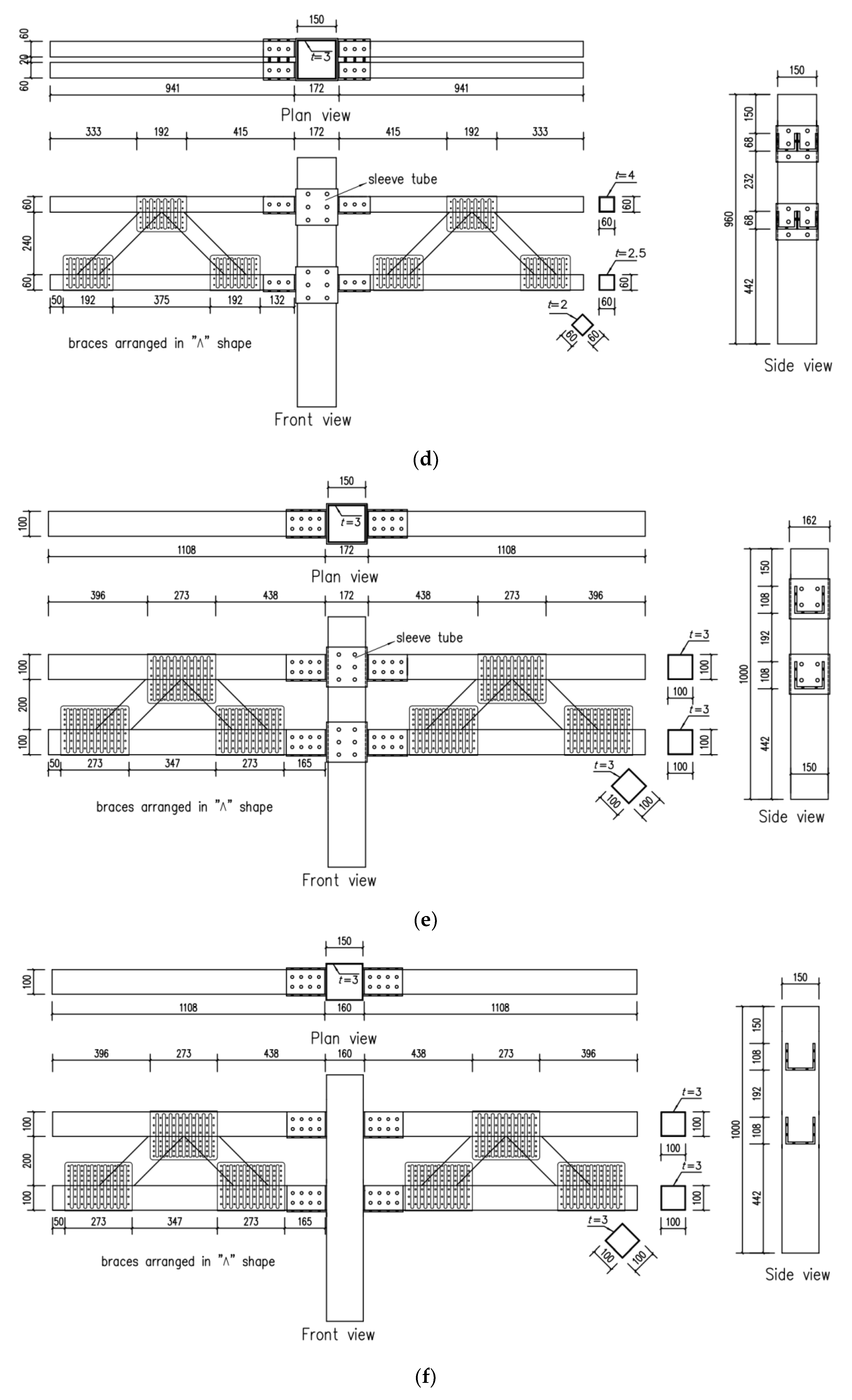
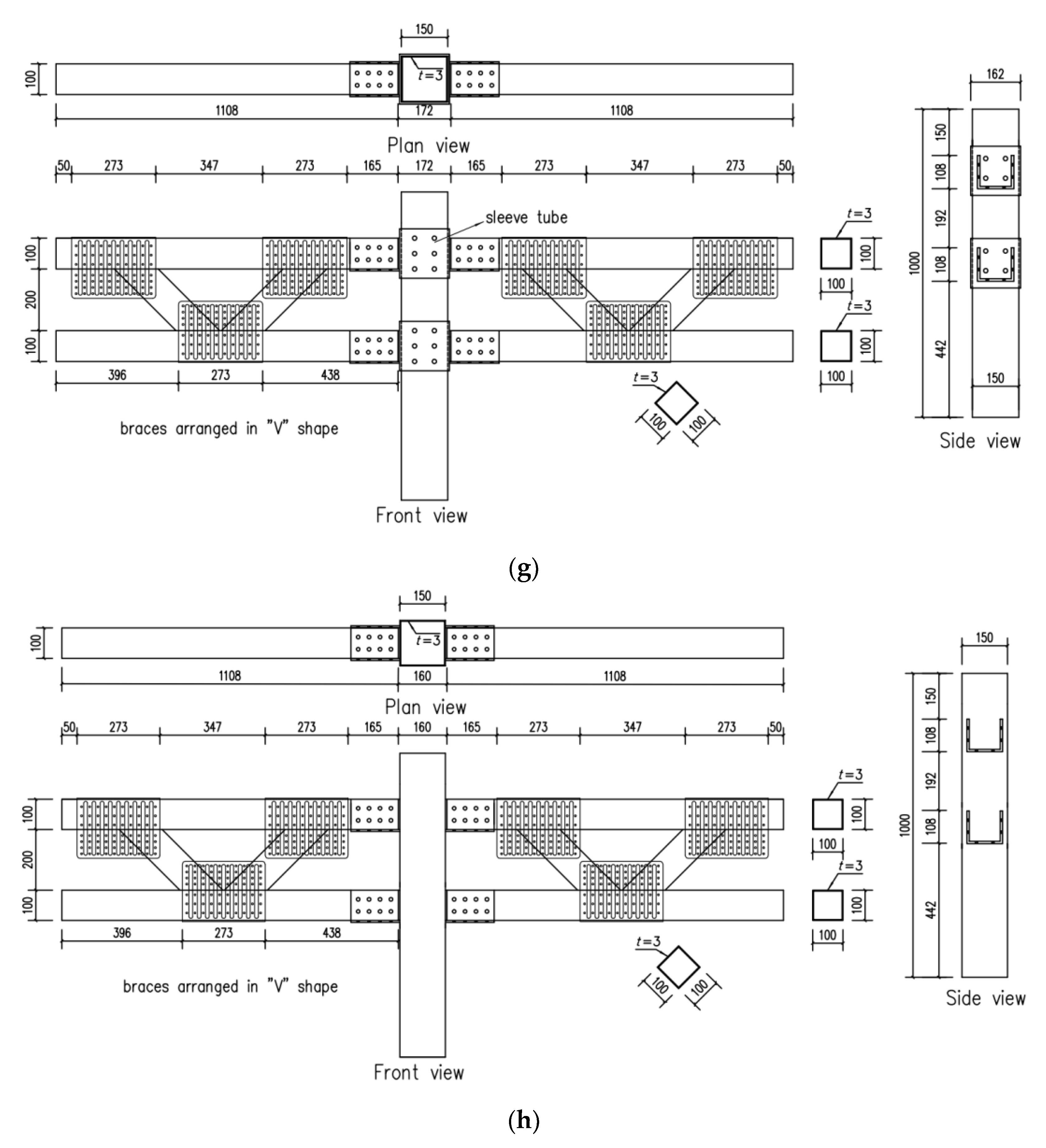
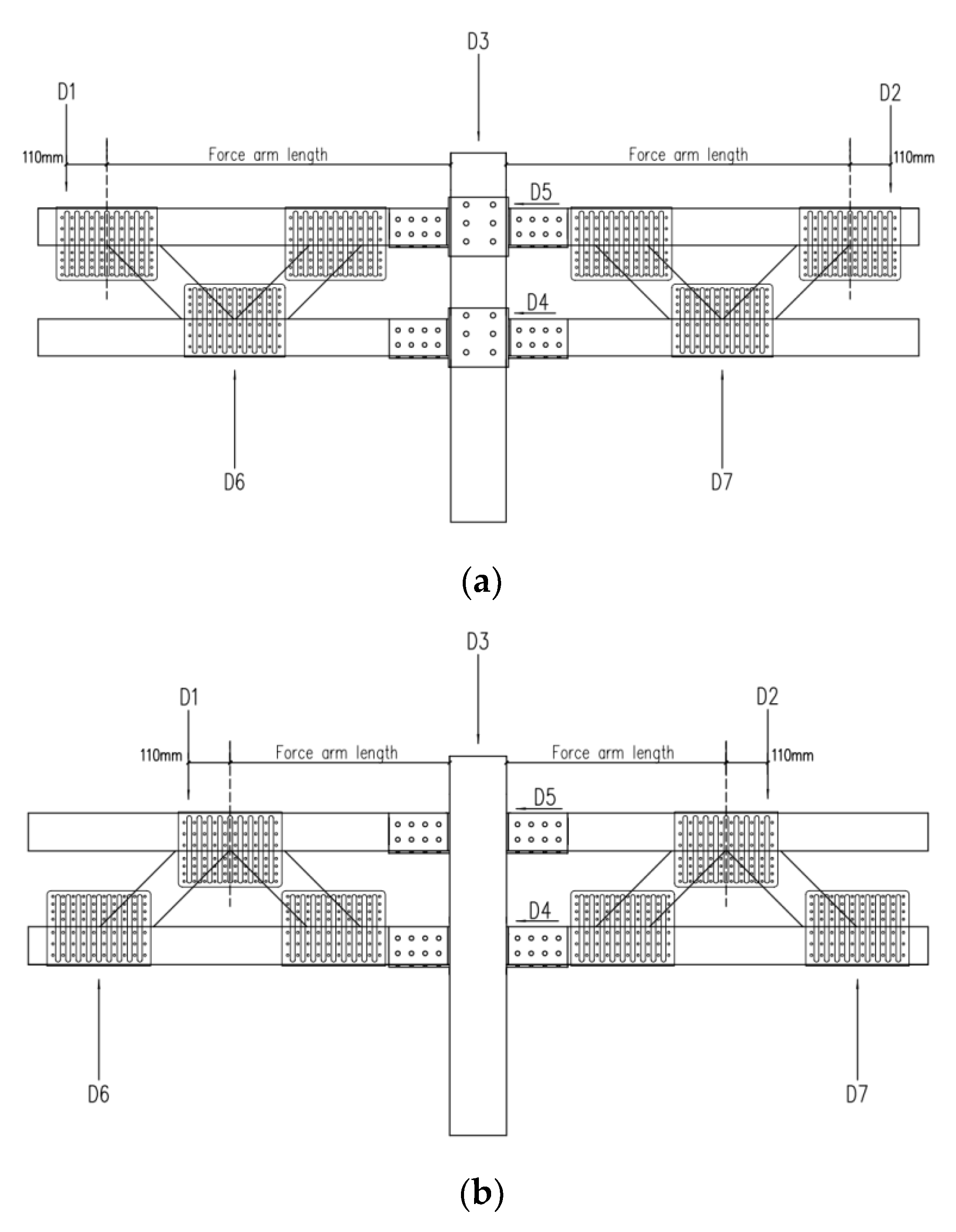
2.1. Configurations and Dimensions of Specimens

In this study, eight cruciform light-steel beam–column connection specimens were fabricated and tested to failure under static monotonic loading. Figure 2a–h shows the numbering, configuration, and dimensions of eight specimens. All the dimensions shown in Figure 2a–h are in mm.
The effect of two configurations of the truss beam on the static bearing capacity of the proposed beam–column connection was investigated (Figure 2a,c). For specimen JU60-1 shown in Figure 2a, two braces of each truss beam are in a “V”-shaped arrangement, whereas those for specimen JU60-3 (Figure 2c) are in a “∧”-shaped arrangement. The motive is to investigate which type of brace arrangement of the truss beam can bring more benefits to the static bearing capacity of the proposed beam–column connection.
Two connection details between the SHS column and the truss-beams can be observed from Figure 2a,b. For the specimen shown in Figure 2a, channel connectors used to connect the truss beams are directly welded to the SHS column by fillet welding; however, for the specimen shown in Figure 2b, channel connectors are welded to the sleeve SHS tube plug-welded to the column. By using the sleeve tube, the SHS column is strengthened locally. Truss beams are bolted to the channel connectors for all specimens.
Double truss beams are used on each side of the cruciform beam–column connection specimens named JU60 (Figure 2a–d), whereas a single truss beam is used for specimens named JU100 (Figure 2e–h). The motive of using double truss beams for specimens named with JU60 was to examine whether they have a higher static bearing capacity compared to specimens named JU100 using a single truss beam.
Two types of U connectors, U60 and U100 (Figure 3a,b) were used to assemble the truss beams of all specimens. The connector shown in Figure 3a was used for specimens JU60-1, JU60-2, JU60-3, and JU60-4, and that shown in Figure 3b was used for four specimens named JU100. First, screw holes were drilled in a thin-walled hot galvanizing steel sheet, which was then stamped to form a U-connector. The pre-drilled screw holes of the U connector prevent sliding of the screw during screw drilling and expedite assembly speed of the truss beam. Dimensions in Figure 3a,b are in mm.
Figure 4a–c shows the connection details between the U connectors and the truss-beam members for specimens JU60-1, JU60-2, JU60-3, and JU60-4. Five self-drilling bolts were used to connecting the U connector and the diagonal SHS brace member, and eight self-drilling bolts were used to connect the U connector and the SHS chord member.
Figure 5a–c shows the connection details between the U connectors and the truss-beam members for specimens JU100-1, JU100-2, JU100-3, and JU100-4. Six self-drilling bolts were used to connect the U connector and the diagonal SHS brace member, and eighteen self-drilling bolts were used to connect the U connector and the SHS chord member.
Because the configurations of the specimens named JU60 and JU100 were different, two types of channel connectors, including single-channel and double-channel connectors to accommodating the end of truss beams, were used in this study. Figure 6 shows the details of the double-channel connectors for specimens JU60-2 and JU60-4; the SHS sleeve tube was plug-welded to the SHS column. Each double-channel connector could accommodate two truss-beams for specimens JU60-2 and JU60-4. For specimens JU60-1 and JU60-3, the same double-channel connectors without the SHS sleeve tube were directly welded to the SHS column.
Figure 7 shows the details of the single-channel connectors for specimens JU100-1 and JU100-3, which were welded to the SHS sleeve tube plug-welded to the SHS column. Each single-channel connector could accommodate one truss beam for specimens JU100-1 and JU100-3. For specimens JU100-2 and JU100-4, the same single-channel connectors without the SHS sleeve tube were directly welded to the SHS column. Dimensions in Figure 6 and Figure 7 are in mm.

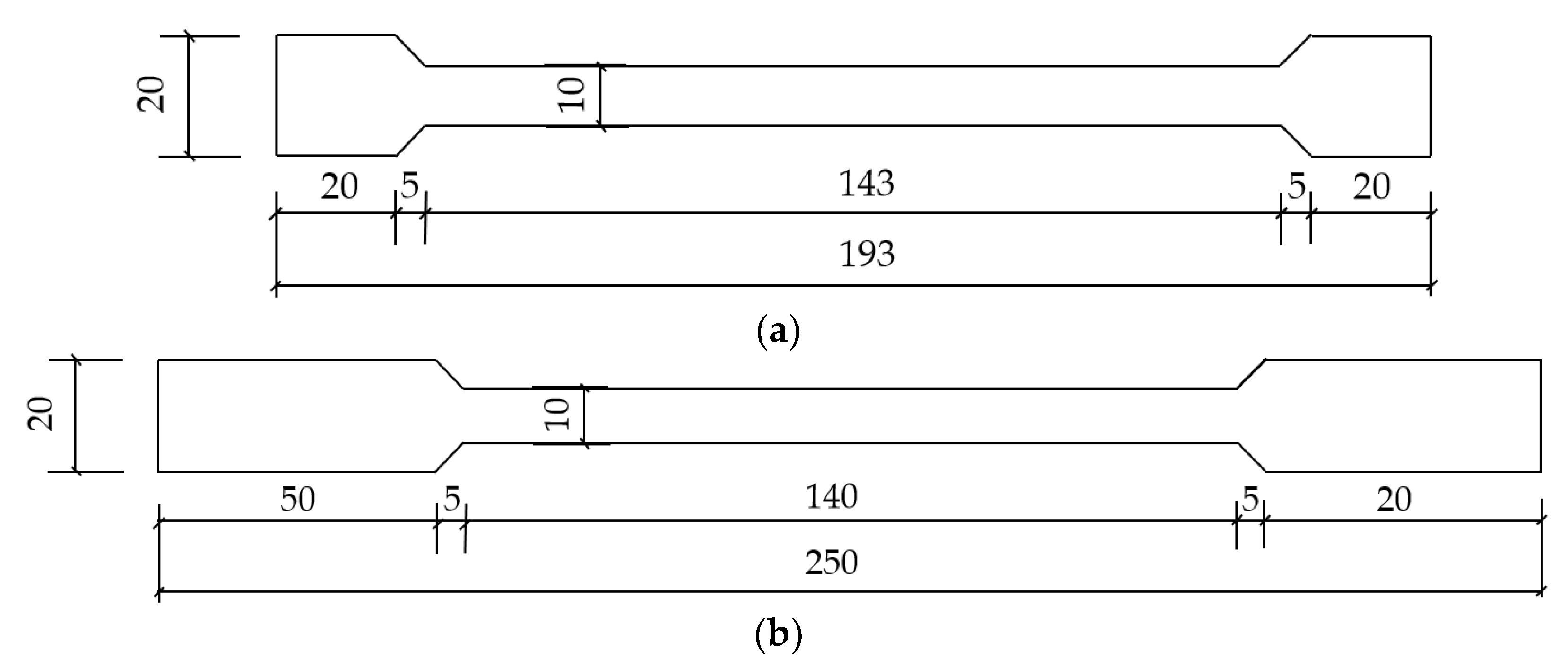
2.2. Steel Material Properties

Coupon test specimens for each type of steel were fabricated and tested. Figure 8a,b shows the dimensions of the coupon specimens for the U-connector steel and other types of steel, respectively. All the coupon specimens were tested to failure using the MTS hydraulic testing machine shown in Figure 9.
Material properties, including yielding stress, ultimate stress, elastic modulus, and elongation rate, of each type of steel are summarized in Table 1. For each type of steel, three coupon specimens were tested, and the value of each material property was determined as the average of three tests. The grade of high-strength bolts was G8.8, and their diameter was 12 mm. The type of self-drilling screws was ST5.5 × 25, with a diameter and length of 5.5 mm and 25 mm, respectively.

2.3. Displacement-Transducer Deployment

Seven displacement transducers were installed to monitor the deformation of each specimen during testing. For specimens JU60-1, JU60-2, JU100-3, and JU100-4, positions of displacement transducers are shown in Figure 10a; for specimens JU60-3, JU60-4, JU100-1, and JU100-2, positions of displacement transducers are shown in Figure 10b. Transducers D1 and D2 were used to measure the displacement of the two loading points at the upper chord.

2.4. Test Rig and Loading Scheme

Figure 11 shows the testing rig for the light-steel beam–column connection specimens. The specimen was placed in between two resisting frames fastened to the ground. The position of the two resisting frames could be adjusted according to the geometry of the specimen. Two manual oil jacks were used to apply vertical loading to each specimen. Loading was measured by force transducers attached to the manual oil jack. Each specimen was placed on the ground. In other words, the ground only provided vertical support to each specimen at the bottom end of the column.
Loading was applied to the specimen in a force-controlled manner. At the beginning of each test, the force interval was set as 2.5 kN. After each interval loading applied, loading was maintained for 1–2 min to record the displacement and force data, as well as observation of the deformation of the specimen and other phenomena. When a rapid increase in the displacement was observed by any of the displacement transducers at the two loading points, the force interval was reduced to 1 kN. Testing was stopped until the manual oil jacks could not apply more loading to the specimen due to sever deformation or fillet weld facture of the specimen. In order to apply equal force to the two loading points of each specimen, the same loading intervals were adopted for the two individual oil jacks at any time in testing.

3. Experimental Results

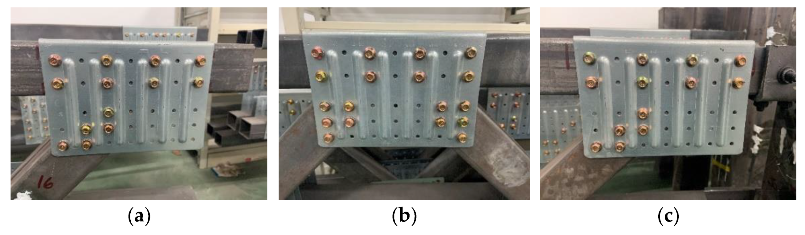
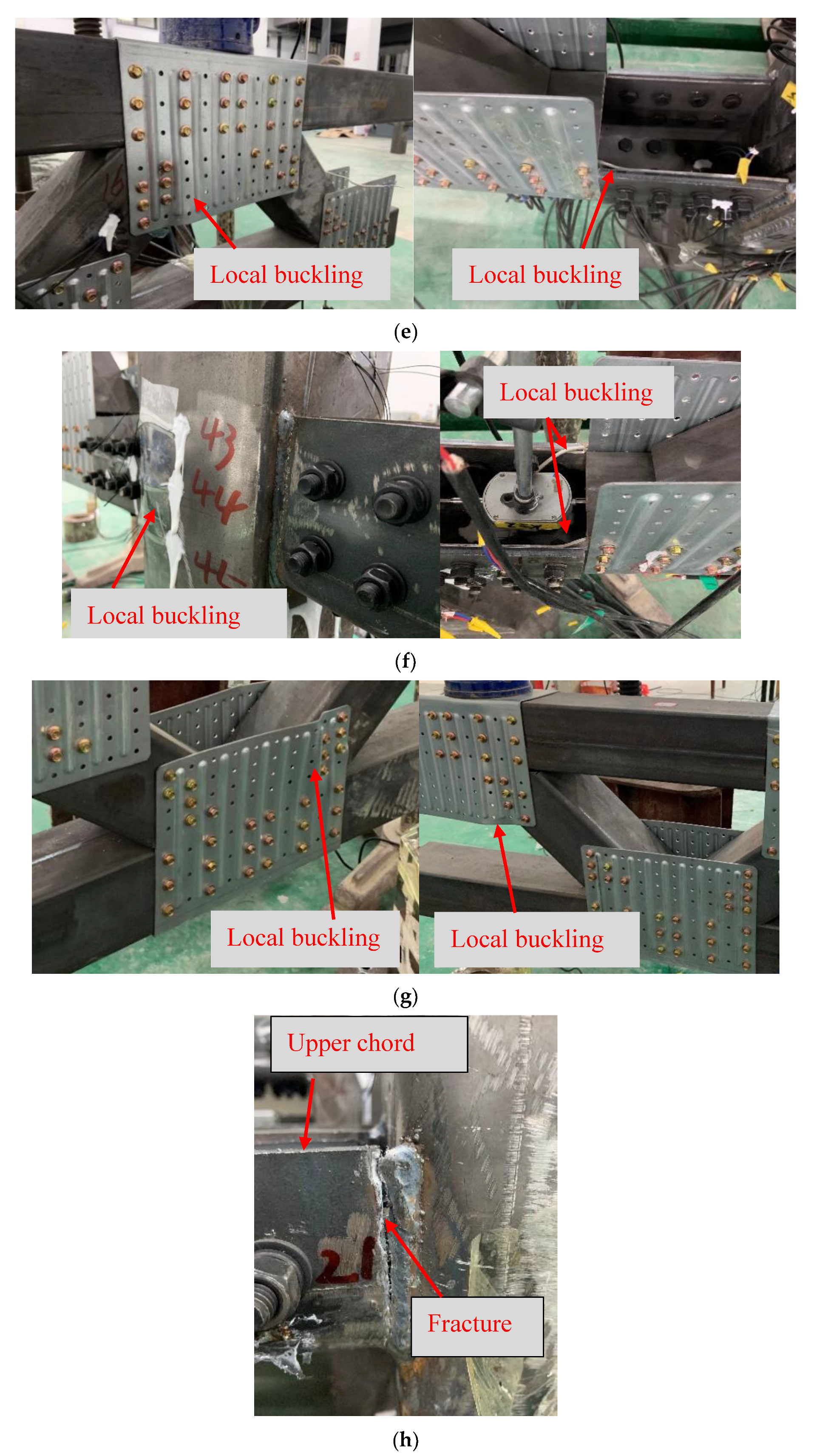
3.1. Deformation and Failure Characteristics

For all specimens, global deflection was observed. Figure 12a–h shows typical local-failure modes of the eight specimens. Table 2 summarizes the local failure modes for each specimen. For the tested specimens, four types of local failure modes were observed, including local column buckling, fillet-weld fracture, U-connector buckling, and local buckling of the slotted region of the chord under compression.
Local column buckling was observed in specimens JU60-1, JU60-3, and JU100-2, as shown in Figure 12a,c,f. Columns of these specimens were without the sleeve tube and very vulnerable to local compressive loading transferred from the below chord of the truss beam.
Fillet-weld fracture was observed in specimens JU60-1, JU60-2, JU60-4, and JU100-4, as shown in Figure 12a,b,d,h. Fillet-weld fracture is mainly attributed to poor welding quality and tension stress acting on the weld transferred from the upper chord of the truss-beam. Therefore, welding quality between the channel connector and the column (or the sleeve tube) should be guaranteed in engineering practice.
U-connector buckling was only observed in specimens JU100-1 and JU100-3, as shown in Figure 12e,g. Columns of the two specimens were locally reinforced by the sleeve tube. In addition, the fillet welds between the channel connectors and the sleeve tubes of the two specimens were sufficiently strong. Therefore, loading applied to specimens JU100-1 and JU100-3 was much higher than that applied to other specimens. U-connector buckling appears to indicate a higher load-bearing capacity for the proposed light-steel beam–column connection.
Local buckling of the slotted region of the below chord has been observed in specimens JU60-3 and JU100-2, as shown in Figure 12c,f. This is probably due to the initial geometry imperfection generated in the slotting process and the distortion of the side wall of the chord’s slotted region introduced in the assembly process. Therefore, it is necessary to control the deformation of the side wall of the slotted region of the chord during slotting and assembly processes.

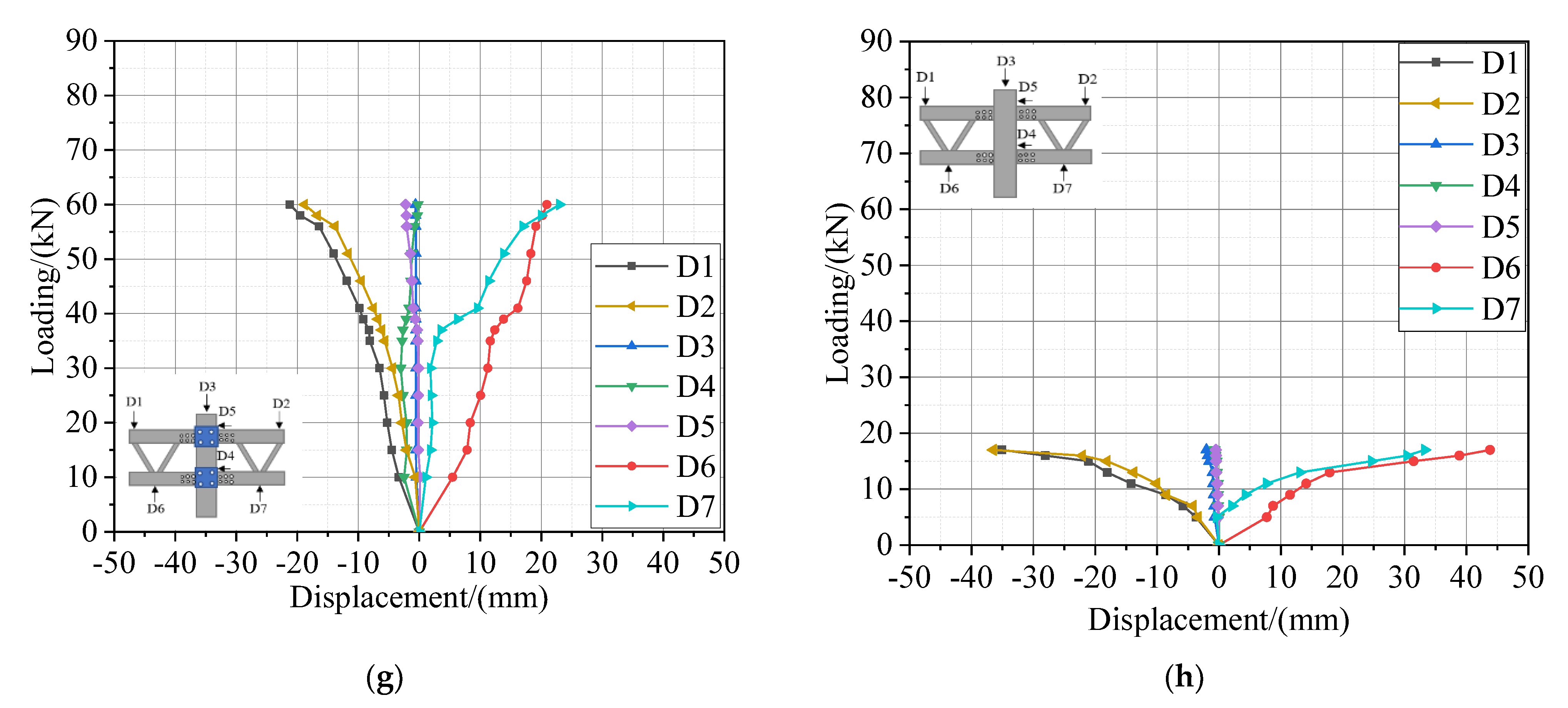
3.2. Loading–Displacement Curves

Figure 13a–h shows the loading–displacement curves of the eight specimens. The maximum and minimum loading values are from specimen JU100-1 and JU100-4, respectively. However, the maximum bending moment, which is equal to the applied loading multiplying the corresponding force-arm, is from specimen JU100-3 (56 kN·m) instead of JU100-1(44.5 kN·m). Table 3 summarizes the maximum loading applied to each specimen and the maximum vertical deflection at the truss-beam end (refer to Figure 10a,b). The maximum vertical deflection is either from the transducer installed on the upper chord (D1 or D2) or the below chord (D6 or D7) of the truss beams.
Displacements measured by symmetrical transducers shown in Figure 10a,b are not identical, for instance, D1 and D2 vs. D6 and D7. This is because it is difficult to maintain identical applied loading with two manual oil jacks during testing.

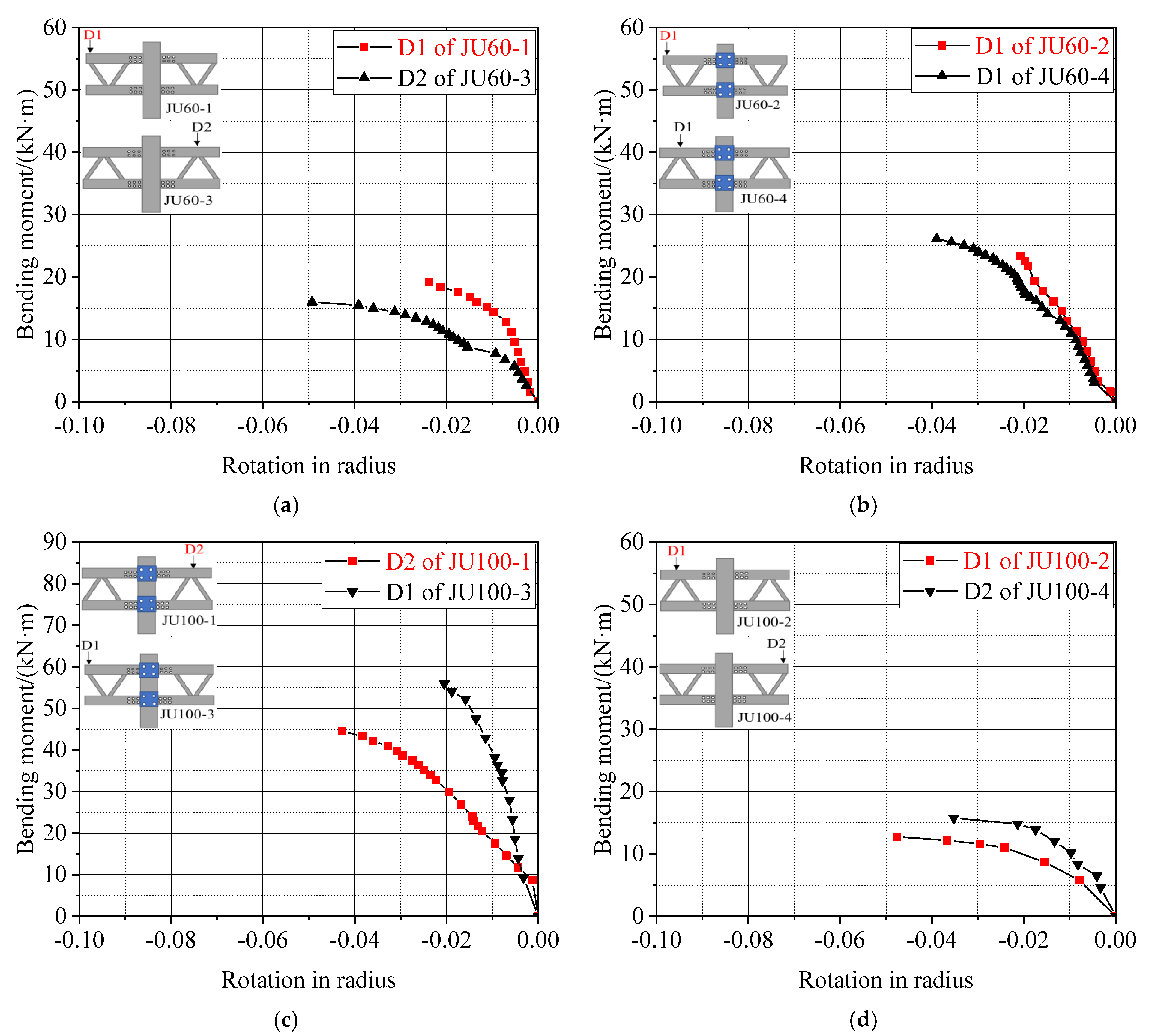
3.3. Effect of the Column Sleeve Tube on the Proposed Beam–Column Connection

Figure 14a–d shows a comparison of the loading–displacement curves of specimens with and without a sleeve tube to reinforce the column. Displacement in Figure 14a–d is from the maximum loading–displacement curves measured from two loading points. A specimen with a sleeve tube has a much higher static bearing capacity compared to its counterpart without a sleeve tube. This means that a sleeve tube plug-welded to the RHS column can effectively increase the static bearing capacity of the proposed light-steel beam–column connection. For the specimens named JU60, the sleeve tube can increase load-bearing capacities by about 29.2–56.3%, whereas for specimens named JU100, the increment is between 245.5% and 252.9%.
In addition to increasing the static bearing capacity of the proposed light-steel beam–column connection, the sleeve tube can also reduce the global deflection of the truss beam.

3.4. Effect of the Truss-Beam Configuration on the Proposed Beam–Column Connection

The effect of the truss-beam configuration, including a “V”- and “∧”-shaped brace arrangement, on the static bearing capacity of the proposed light-steel beam–column connection is investigated in this section. This is because for specimens with different truss-beam configurations, the position of the loading point is different. To make a direct comparison and investigate the effect of the truss-beam configuration, loading–displacement curves were converted to the moment–rotation curves. Figure 15a–d shows a comparison of moment–rotation curves of specimens with “V”- and “∧”-shaped brace arrangements of the truss beams. The light-steel beam–column specimen has a higher load-bearing capacity and a lower global deflection of the truss beam when the brace members are arranged in a “V” shape, such as in specimen JU60-1.

3.5. Effect of the Truss-Beam Type on the Proposed Beam–Column Connection

The effect of the truss-beam type, including double-truss and single-truss beams, on the static bearing capacity of the proposed light-steel beam–column connection is investigated in this section. Figure 16a–d shows a comparison between specimens using double-truss and single-truss beams. For specimens without a sleeve tube to reinforce the column, the comparison shown in Figure 16a,c reveals that the specimen consisting of double-truss beams have a higher load-bearing capacity and a lower global deflection compared to the specimen composed of single-truss beams; however, the comparison shown in Figure 16b,d reveals that the specimens consisting of single-truss beams have a higher load-bearing capacity and a lower deflection compared to the specimens composed of double-truss beams, where the column is reinforced by a sleeve tube. For the specimens without a sleeve tube, a specimen with double-truss beams may have a 22.3–29.9% increment of the loading capacity compared to the specimens using single-truss beams. For specimens with a sleeve tube, a specimen with single-truss beams may have a 70.5–124% increment of the loading capacity compared to specimens using double-truss beams.

4. Conclusions

In this study, we investigated the structural performance of the proposed light-steel beam–column connection by carrying out experimental tests. Eight cruciform specimens with different configurations were tested to failure under balanced vertical loading. The effect of three primary parameters on the load-bearing capacity of the proposed connection and the deflection of the truss beam were investigated, i.e., truss-beam configuration, truss-beam type, and with or without sleeve tube reinforcement. Based on the experimental results, the following conclusions can be drawn:
(1)
A sleeve tube plug-welded to the thin-wall RHS column can significantly increase the static bearing capacity of the proposed connection because it can effectively prevent local buckling of the RHS column. In engineering practice, it is recommended to use a sleeve tube to locally reinforce the thin-wall RHS column for the proposed connection.
(2)
The light-steel beam–column connection has a higher load-bearing capacity and a lower deflection of the truss-beam when the brace members are arranged in a “V” shape.
(3)
For specimens without a sleeve tube to reinforce the thin-wall RHS column, those with double-truss beams have a higher load-bearing capacity and a lower deflection compared to their counterpart composed of single-truss beams. However, for specimens with a column locally reinforced with a sleeve tube a single-truss beam has a higher load-bearing capacity and a lower deflection compared to the counterpart composed of double-truss beams. Because double-truss beams are more troublesome to fabricate and require more material, it is recommended to use single-truss beams for the proposed light-steel beam–column connection.
(4)
For all the specimen tested, four types of local failure were observed: local column buckling, fillet-weld fracture, U-connector buckling, and local buckling of the slotted region of the chord under compression. Local column buckling can be prevented by using a sleeve tube. Fillet-weld quality should be guaranteed to avoid early failure of the connection due to weld fracture. U-connector buckling was only observed for specimens JU100-1 and JU100-3, and it appears that U-connector buckling only occurs when the fillet weld of the proposed beam–column connection is sufficiently strong. In order to reduce local failure of the slotted region of the chord under compression, it is necessary to control the deformation of the sidewall of the slotted region of the chord during slotting and assembly processes.
Due to a lack of suitable loading system, the authors had to apply the monotonic loading to each specimen using two manual oil jacks in a force–control manner. Therefore, loading–displacement data after the peak load was obtained. In fact, it is preferred to apply the monotonic force simultaneously to the two loading points of each specimen in a displacement–control manner so that the full loading–displacement curves can be obtained. More experimental tests are needed to propose a design approach for the proposed light-steel beam–column connection.

Author Contributions

Conceptualization, X.W.; methodology, X.W.; investigation, X.L. and F.L.; writing—original draft preparation, T.L. and H.W.; writing—review and editing, T.L. and X.X.; supervision, X.W. and Z.S. All authors have read and agreed to the published version of the manuscript.

Funding

This study was funded by the Major Science and Technology Program Projects of Hainan Province (ZDKJ2021024), the Key Research and Development Program of Hainan Province (ZDYF2021GXJS211), the Foundation of Zhongshan Institute of Advanced Engineering Technology of WHUT (WHUT202002), and the National Natural Science Foundation of China (51908437).

Institutional Review Board Statement

Not applicable.

Informed Consent Statement

Not applicable.

Data Availability Statement

The data used to support the findings of this study are available from the corresponding author upon request.

Acknowledgments

The authors express their gratitude towards the Structural Test Center of Wuhan University of Technology. The authors also appreciate all assistance from Master’s students on the research team during the testing and simulation processes.

Conflicts of Interest

The authors declare that they have no conflict of interest.

References

  1. Zaharia, R.; Dubina, D. Stiffness of joints in bolted connected cold-formed steel trusses. J. Constr. Steel Res. 2006, 62, 240–249. [Google Scholar] [CrossRef]
  2. Dawe, J.L.; Liu, Y.; Li, J.Y. Strength and behaviour of cold-formed steel offset trusses. J. Constr. Steel Res. 2010, 66, 556–565. [Google Scholar] [CrossRef]
  3. Sabbagh, A.B.; Petkovski, M.; Pilakoutas, K.; Mir-ghaderi, R. Ductile moment-resisting frames using cold-formed steel sections: An analytical Investigation. J. Constr. Steel Res. 2011, 67, 634–646. [Google Scholar] [CrossRef]
  4. Sabbagh, A.B.; Petkovski, M.; Pilakoutas, K.; Mir-ghaderi, R. Cyclic behaviour of bolted cold-formed steel moment connections: FE modelling including slip. J. Constr. Steel Res. 2013, 80, 100–108. [Google Scholar] [CrossRef]
  5. Mathieson, C.; Clifton, G.C.; Lim, J.B.P. Novel pin-jointed connection for cold-formed steel trusses. J. Constr. Steel Res. 2016, 116, 173–182. [Google Scholar] [CrossRef]
  6. Mathieson, C.; Roy, K.; Clifton, C.; Ahmadi, A.; Lim, J.B.P. Failure mechanism and bearing capacity of cold-formed steel trusses with HRC connectors. Eng. Struct. 2019, 201, 109741. [Google Scholar] [CrossRef]
  7. Henriques, J.; Rosa, N.; Gervasio, H.; Santos, P.; Silva, L.S. Structural performance of light steel framing panels using screw connections subjected to lateral loading. Thin-Walled Struct. 2017, 121, 67–88. [Google Scholar] [CrossRef]
  8. Bondok, D.H.; Salim, H.A. Failure capacities of cold-formed steel roof trusses end-connections. Thin-Walled Struct. 2017, 121, 57–66. [Google Scholar] [CrossRef]
  9. Bučmys, Ž.; Daniūnas, A.; Jaspart, J.; Demonce-au, J. A component method for cold-formed steel beam-to-column bolted gusset plate joints. Thin–Walled Struct. 2018, 123, 520–527. [Google Scholar] [CrossRef]
  10. McCrum, D.P.; Simon, J.; Grimes, M.; Broderick, B.M.; Lim, J.B.P.; Wrzesien, A.M. Experimental cyclic performance of cold-formed steel bolted moment resisting frames. Eng. Struct. 2019, 181, 1–14. [Google Scholar] [CrossRef] [Green Version]
  11. Ye, J.; Mojtabaei, S.M.; Hajirasouliha, I. Seismic performance of cold-formed steel bolted moment connections with bolting friction-slip mechanism. J. Constr. Steel Res. 2019, 156, 122–136. [Google Scholar] [CrossRef] [Green Version]
  12. Ye, J.; Mojtabaei, S.M.; Hajirasouliha, I.; Pilakoutas, K. Efficient design of cold-formed steel bolted-moment connections for earthquake resistant frames. Thin-Walled Struct. 2020, 150, 105926. [Google Scholar] [CrossRef]
  13. Dizdar, Ç.; Baran, E.; Topkaya, C. Strength and stiffness of floor trusses fabricated from cold-formed steel lipped channels. Eng. Struct. 2019, 181, 437–457. [Google Scholar] [CrossRef]
  14. Natesan, V.; Madhavan, M. Experimental study on beam-to-column clip angle bolted connection. Thin-Walled Struct. 2019, 141, 540–553. [Google Scholar] [CrossRef]
  15. Natesan, V.; Shanmugasundaram, B.; Madhavan, M. Comparative experimental studies on the web cleat bolted CFSbeam-to-column connection. J. Constr. Steel Res. 2020, 170, 106080. [Google Scholar] [CrossRef]
  16. Song, L.; Yan, W.; Yu, C.; Xie, Z.; Tan, Q. Flexural behavior investigation of the CFS truss beams with self-piercing riveted connection. J. Constr. Steel Res. 2019, 156, 28–45. [Google Scholar] [CrossRef]
  17. Song, L.; Yan, W.; Zhang, X.; Yu, C.; Xie, Z. Feasibility research on the application of self-piercing riveted connection in cold-formed steel structures. J. Constr. Steel Res. 2020, 168, 105957. [Google Scholar] [CrossRef]
  18. Fahmy, A.S.; Swelem, S.M.; Mussttaf, H.H. Beam-Column Connections Behavior of Cold-Formed Steel Members: New Experimental Configuration. KSCE J. Civ. Eng. 2020, 24, 2147–2159. [Google Scholar] [CrossRef]
  19. Wang, J.; Wang, W.; Xiao, Y.; Guo, L. Cyclic behavior tests and evaluation of CFS truss composite floors. J. Build. Eng. 2021, 35, 101974. [Google Scholar] [CrossRef]
  20. Chen, X.; Blum, H.B.; Roy, K.; Pouladi, P.; Uzzaman, A.; Lim, J.B.P. Cold-formed steel portal frame moment-resisting joints: Behaviour, capacity and design. J. Constr. Steel Res. 2021, 183, 106718. [Google Scholar] [CrossRef]
  21. Wang, F.; Han, Y.; Yang, J. Nonlinear FE analysis on stiffness and resistance of bolted cold-formed steel built-up joints. Structures 2021, 33, 2520–2533. [Google Scholar] [CrossRef]
  22. Osman, H.S.; Serror, M.H.; Fathallah, E. Numerical study on the rotation capacity of SIP-strengthened cold-formed steel beams. Eng. Struct. 2022, 251, 113542. [Google Scholar] [CrossRef]
  23. Wang, X.; Yuan, X.; Zeng, H.; Li, T.; Liang, Y.; Gao, X.; Yu, Y. Bearing capacity and failure mode of a light-steel tubular K-joint connected by a novel U-shape connector. Appl. Sci. 2021, 11, 8587. [Google Scholar] [CrossRef]
Figure 1. General composition of the cruciform light-steel beam–column connection.
Applsci 12 04387 g001
Figure 2. Numbering, configuration, and dimensions of eight specimens. (a) JU60−1, (b) JU60−2, (c) JU60−3, (d) JU60−4, (e) JU100−1, (f) JU100−2, (g) JU100−3, (h) JU100−4.
Applsci 12 04387 g002aApplsci 12 04387 g002bApplsci 12 04387 g002c
Figure 3. U connectors for assembling truss beams. (a) U60, (b) U100.
Applsci 12 04387 g003
Figure 4. Connection details between the U connectors and the truss-beam members for specimens named JU60. (a) Node at free end of the beam, (b) node in the middle, (c) node adjacent to the column.
Applsci 12 04387 g004
Figure 5. Connection details between the U connectors and the truss-beam members for specimens named JU100. (a) Node at free end of the beam, (b) node in the middle, (c) node adjacent to the column.
Applsci 12 04387 g005
Figure 6. Double-channel connector welded with the SHS sleeve tube.
Applsci 12 04387 g006
Figure 7. Single-channel connector welded with the SHS sleeve tube.
Applsci 12 04387 g007
Figure 8. Coupon test specimens. (a) U connector, (b) other steel.
Applsci 12 04387 g008
Figure 9. MTS hydraulic testing machine.
Applsci 12 04387 g009
Figure 10. Positions of displacement transducers. (a) For specimens JU60−1, JU60−2, JU100−3, and JU100−4; (b) for specimens JU60−3, JU60−4, JU100−1, and JU100−2.
Applsci 12 04387 g010
Figure 11. Testing rig.
Applsci 12 04387 g011
Figure 12. Local deformation and failure characteristics of the eight specimens. (a) JU60−1, (b) JU60−2, (c) JU60−3, (d) JU60−4, (e) JU100−1, (f) JU100−2, (g) JU100−3, (h) JU100−4.
Applsci 12 04387 g012aApplsci 12 04387 g012b
Figure 13. Loading−displacement curves of all specimens. (a) JU60−1, (b) JU60−2, (c) JU60−3, (d) JU60−4, (e) JU100−1, (f) JU100−2, (g) JU100−3, (h) JU100−4.
Applsci 12 04387 g013aApplsci 12 04387 g013b
Figure 14. Effect of the column sleeve tube on the proposed beam−column connection. (a) JU60−1 and JU60−2, (b) JU60−3 and JU60−4, (c) JU100−1 and JU100−2, (d) JU100−3 and JU100−4.
Applsci 12 04387 g014
Figure 15. Effect of the truss−beam configuration on the proposed beam−column connection. (a) JU60−1 and JU60−3, (b) JU60−2 and JU60−4, (c) JU100−1 and JU100−3, (d) JU100−2 and JU100−4.
Applsci 12 04387 g015
Figure 16. Effect of truss−beam type on the proposed connection. (a) JU60−1 and JU100−4, (b) JU60−2 and JU100−3, (c) JU60−3 and JU100−2, (d) JU60−4 and JU100−1.
Applsci 12 04387 g016
Table 1. Material properties of each steel.
ComponentYield Stress
(MPa)
Elastic Modulus
(Gpa)
Ultimate Stress
(Mpa)
Elongation Rate
(%)
SHS brace members of specimens named JU6034220240924.2
Upper SHS chord members of specimens named JU6027419643826.2
Below SHS chord members of specimens named JU6033321341414.3
SHS chord and brace members of specimens named JU10030320246722.2
SHS column30720546721.0
SHS sleeve tube34321347724.4
Channel connector48821355418.6
U60 U connector31417933122.9
U100 U connector28621331221.1
Table 2. Summary of the global and local failure modes.
SpecimenSleeve TubeDeformation and Failure Characteristics
JU60-1NoTruss-beam global deflection; local column buckling; fillet-weld fracture
JU60-2YesTruss-beam global deflection; fillet-weld fracture
JU60-3NoTruss-beam global deflection; local column buckling; local buckling of the slotted region of the below chord
JU60-4YesTruss-beam global deflection; fillet-weld fracture
JU100-1YesTruss-beam global deflection; U-connector buckling
JU100-2NoTruss-beam global deflection; local column buckling; local buckling of the slotted region of the below chord
JU100-3YesTruss-beam global deflection; U-connector buckling
JU100-4NoTruss-beam global deflection; fillet-weld fracture
Table 3. The maximum loading and vertical deflection at the truss-beam end.
Specimen No.Channel Connector TypeSleeve TubeTruss-Beam ConfigurationMaximum Loading/(kN)Maximum Vertical Deflection/(mm)Arm Length/(mm)Maximum Bending Moment/(kN m)
JU60-1Double-channelNo“V”-shaped brace arrangement2424.780019.2
JU60-2Double-channelYes“V”-shaped brace arrangement3124.680625.0
JU60-3Double-channelNo“∧”-shaped brace arrangement3234.051616.5
JU60-4Double-channelYes“∧”-shaped brace arrangement5043.252226.1
JU100-1Single-channelYes“∧”-shaped brace arrangement7629.5585.544.5
JU100-2Single-channelNo“∧”-shaped brace arrangement2239.2579.512.7
JU100-3Single-channelYes“V”-shaped brace arrangement6023.0932.556.0
JU100-4Single-channelNo“V”-shaped brace arrangement1743.8926.515.7
Publisher’s Note: MDPI stays neutral with regard to jurisdictional claims in published maps and institutional affiliations.

