Article

Fast Extraction of Coupling of Modes Parameters for Surface Acoustic Wave Devices Using Finite Element Method Based Simulation

School of Electronic Information and Electrical Engineering, Shanghai Jiao Tong University, Shanghai 200240, China
*
Author to whom correspondence should be addressed.
Appl. Sci. 2022, 12(9), 4547; https://doi.org/10.3390/app12094547
Submission received: 8 April 2022 / Revised: 24 April 2022 / Accepted: 27 April 2022 / Published: 30 April 2022

Abstract

:
The finite element method (FEM) has been applied to extract the coupling-of-modes (COM) parameters of surface acoustic wave (SAW) devices for a long time. It always involves calculating the dispersive curves or harmonic admittance, which makes the extraction process and results sophisticated, time-consuming and inaccurate. Therefore, a simple method is proposed to extract all COM parameters of the SAW devices rapidly and accurately in this paper. It is based on the FEM and combines the stationary analysis with modal analysis. We have described in detail the basic principles and procedures of the proposed method, and made a comprehensive comparison between the proposed method and the other two existing methods. We have also examined the proposed method by extracting COM parameters of some common SAW substrate, and compared our extracted results with those reported in the other literatures. Results show that our proposed method holds higher accuracy and more efficiency (~s order) than the others (~h order). Moreover, our extracted COM parameters are in an excellent agreement with those reported in the other literatures.

1. Introduction

Surface acoustic wave (SAW) devices have expanded into diverse application fields such as filters, sensors and radio frequency identification (RFID) tags [1,2,3,4]. Accurate and efficient simulation methods are crucial for designing high-performance SAW devices. Several methods have been proposed for modeling and analyzing the characteristics of SAW devices [5,6,7,8], including the earlier δ-function models, equivalent circuit models and the later coupling-of-modes (COM) equations, finite element method/boundary element method (FEM/BEM), etc. However, the first two methods cannot take into account the interdigital transducer (IDT)’s internal reflections. Though the FEM/BEM model is considered to be the most accurate simulation method, it is time-consuming [7]. Therefore, the COM method is widely used for analyzing and designing SAW devices for the reason that it is extremely fast and holds enough accuracy. Regardless of the accuracy of the model itself, the accuracy of this method entirely depends on the accuracy of the COM parameters (SAW velocity v, reflectivity κ, transduction coefficient α, static capacitance C and propagation attenuation γ). Thus, obtaining accurate COM parameters is crucial for designing SAW devices. To obtain these key parameters, perturbation theory [9] and measurement harmonic admittance [10] have been proposed, but they are either costly or lack of accuracy. FEM-based methods FEM/spectral domain analysis (FEM/SDA) [11] and FEM/BEM [12] have also been employed in COM parameters extraction, but they are invalid for the multilayer structures. Recently, the pure FEMs, especially in combination with the existing commercial software such as ANSYS and COMSOL Multiphysics, have been attractively studied to extract these parameters [13,14,15]. They can conquer the problems mentioned above and several methods have been proposed, which can be divided into two branches: one is by calculating the dispersion characteristics [16,17]. The SAW velocity at different frequencies (dispersive curves) is calculated, which is realized by applying the Floquet boundary conditions, under short-circuit (SC) and open-circuit (OC) conditions. Then, SAW velocity v, reflectivity κ, transduction coefficient α and static capacitance C are obtained by finding the stopband edges and fitting the dispersive curves, respectively. Such methods are sophisticated and time-consuming for the reason that velocity at each frequency must be calculated. The other is by calculating the Harmonic Admittance (HA) [18]. The COM parameters are obtained from the HA in the same way as the former. The harmonic analysis is time-consuming because the computation time is proportional to the number of frequency points. Moreover, the accuracy totally depends on the step length of frequency, which makes the extracted parameters not exactly accuracy.
Thus, in this paper, we propose a simple and fast method, performed by COMSOL Multiphysics, to extract accurate COM parameters of SAW devices. It is based on the FEM and combines the stationary analysis with modal analysis. Firstly, we describe in detail the basic principles and procedures of the proposed method. Then, we make a comprehensive comparison between the proposed method and the other two existing methods which are both based on the harmonic analysis. Finally, we examine the proposed method by extracting COM parameters of some common SAW substrates (ST quartz, ST-25°X quartz and Y-51.25°Z LiTaO3), and compare our extracted results with those reported in the other literatures.

2. Methods

2.1. Solutions of COM Equations

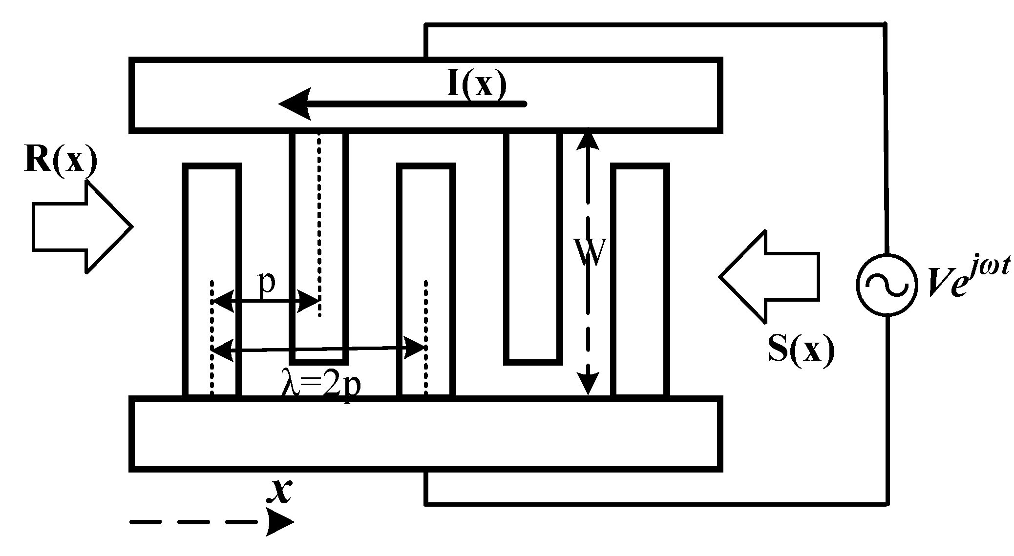
Figure 1 shows the schematic of COM model for the IDT, in which W is the aperture length, p is the pitch of the IDT, the wavelength (λ) is the twice of the pitch (λ = 2p). A drive voltage V connect over the bus bars of the IDT excites waves. In reverse, the waves propagating under the electrodes cause flow of the current I. The R(x) and S(x) represent the slowly varying amplitudes of the modes propagating in the positive and negative x-directions, respectively.
The presence of the electrodes on the surface introduces a coupling between the modes. Assuming a linear coupling between the amplitudes due to reflectivity, and a linear transduction coefficient due to piezoelectricity, the final COM equation can be obtained [7]:
d R x d x = j δ R x + j κ S x + j α V , d S x d x = j δ S x j κ * S x j α * V , d I x d x = 2 j α * R x 2 j α S x + j ω C V ,
where δ is the detuning parameter:
δ = k k 0 = k r k 0 j γ = ω ν k 0 j γ ,
k is the complex wavenumber, k = kr − jγ, kr is the resonance wavenumber and k0 is the center wavenumber, k0 = 2π/λ = π/p. The COM parameters of the model are velocity v, reflectivity κ, transduction coefficient α, static capacitance per unit length C and propagation attenuation γ (superscript * denotes the complex conjugate). These parameters are determined from the simulation of an infinite periodic grating under different boundary conditions [19].
When considering no attenuation (γ = 0), the equation system (1) under SC conditions (i.e., V = 0) gives the relationships between stopband edges and velocity v, reflectivity κ:
ν = λ f s c + + f s c 2 κ λ = 2 π f s c + f s c f s c + + f s c
Under OC conditions (i.e., I = 0), the equation system (1) gives the relationships between stopband edges and transduction coefficient α, directivity phase φ:
α n = ω C n λ π f o c + + f o c f s c + + f s c 1 cos φ = cos α 2 / κ = ( f o c + f o c ) 2 ( f s c + f s c ) 2 f o c + + f o c f s c + + f s c 2 2 f s c + + f s c f o c + + f o c f s c + + f s c
where αn is the normalized transduction coefficient, namely, αn = αλ/√(W/λ). Cn is the normalized static capacitance, Cn = /W. The φ is the directivity phase, namely, φ = 2φαφκ, where φα and φκ are the phases of α and κ. Equations (2) and (3) imply that all COM parameters, except the attenuation γ, can be obtained from the lower and upper edges of the SC and OC stopbands (fSC, fSC+, fOC, fOC+), if the C was previously extracted or given.

2.2. Extraction Method

Based on this, we propose a simple method, performed by COMSOL Multiphysics, to rapidly extract accurate COM parameters. It is divided into two steps: stationary analysis and modal analysis.
At first, stationary analysis is adopted to extract the C, which employs the FEM/PML model in this paper. Figure 2 shows a single wavelength primitive cell of the infinitely periodic IDTs on the piezoelectric substrate. A perfectly matched layer (PML) is placed at the bottom of the substrate to avoid reflections from the bottom [20]. An air layer is taken into account due to the charge on the IDT-air interfaces [21]. The solid mechanical field and electrostatic field of COMSOL are coupled. The detailed boundary conditions are listed in Table 1. The stationary analysis is performed with a voltage drop ΔV loaded between the left and right electrode. When the analysis is done, the normalized static capacitance Cn can be deduced from the electrostatic field energy We, namely:
C n = 2 W e Δ V 2 W .
Thus, the static capacitance per unite C can be extracted.
Then, modal analysis is adopted to extract the remaining COM parameters. That is, model analysis is performed to solve the eigenvalues under SC and OC conditions. These eigenvalues correspond to fSC, fSC+, fOC, fOC+, which are the key values to determine the remaining COM parameters. The SC and OC conditions are realized by setting zero voltage and charge, respectively, at the electrode-solid interfaces (Γ+, Γ). The detailed boundary conditions for the modal analysis are given in Table 2. Finally, meshing the primitive cell. Mesh division determines the solution mode of the model and directly affects the calculation time and accuracy. In this work, the boundary surface is firstly meshed, and then the whole model is meshed along the thickness direction.

3. Comprehensive Comparison of Different Extraction Methods

In this section, we make a comprehensive comparison between the proposed method and the other two methods, which are both based on the harmonic analysis. The analysis calculates the harmonic admittance, of which resonance and anti-resonance frequencies (fr, fa) correspond to edges of the stopbands. Thus, finding the resonance and anti-resonance frequencies can determine the COM parameters. However, in some particular cases, the two required modes cannot be simultaneously excited, but it can be conquered by adding a tiny directivity [22]. To achieve this, there are two methods. One is adding a tiny directivity naturally, that is, slightly changing the Euler angle to make the substrate unidirectional. The other is adding a tiny directivity structurally, that is, the wavelength (λ) slightly differs from the period (2p). It can be realized by the Floquet boundary conditions with a tiny detuning: kx = (1 + Δ)k0, where the Δ is a tiny proportion. For the sake of convenience, in the following text, we use method 1, 2 and 3 to denote our proposed method and the other two methods, respectively. The detailed settings of boundary conditions are listed in Table 2 for the three different methods, where Di is the electrical displacement and ni is the normal vector of S.
We have extracted all COM parameters of the ST quartz substrate with the three different methods. We considered the same configuration as presented in [23], where the pitch of IDT was p = 3.932 µm, the aluminum thin film thickness was 160 nm, and the finger width to pitch ratio was m/p= 0.5. The material constants were taken from ref. [24]. The sparse direct solver PARDISO was employed in the FEM calculation. The calculation was run on a 20 cores 2.2 GHz Xeon computer with 128 GB of RAM. The computation time of the method 1 was 30 s, while that of the others were both 1 h 3 min.
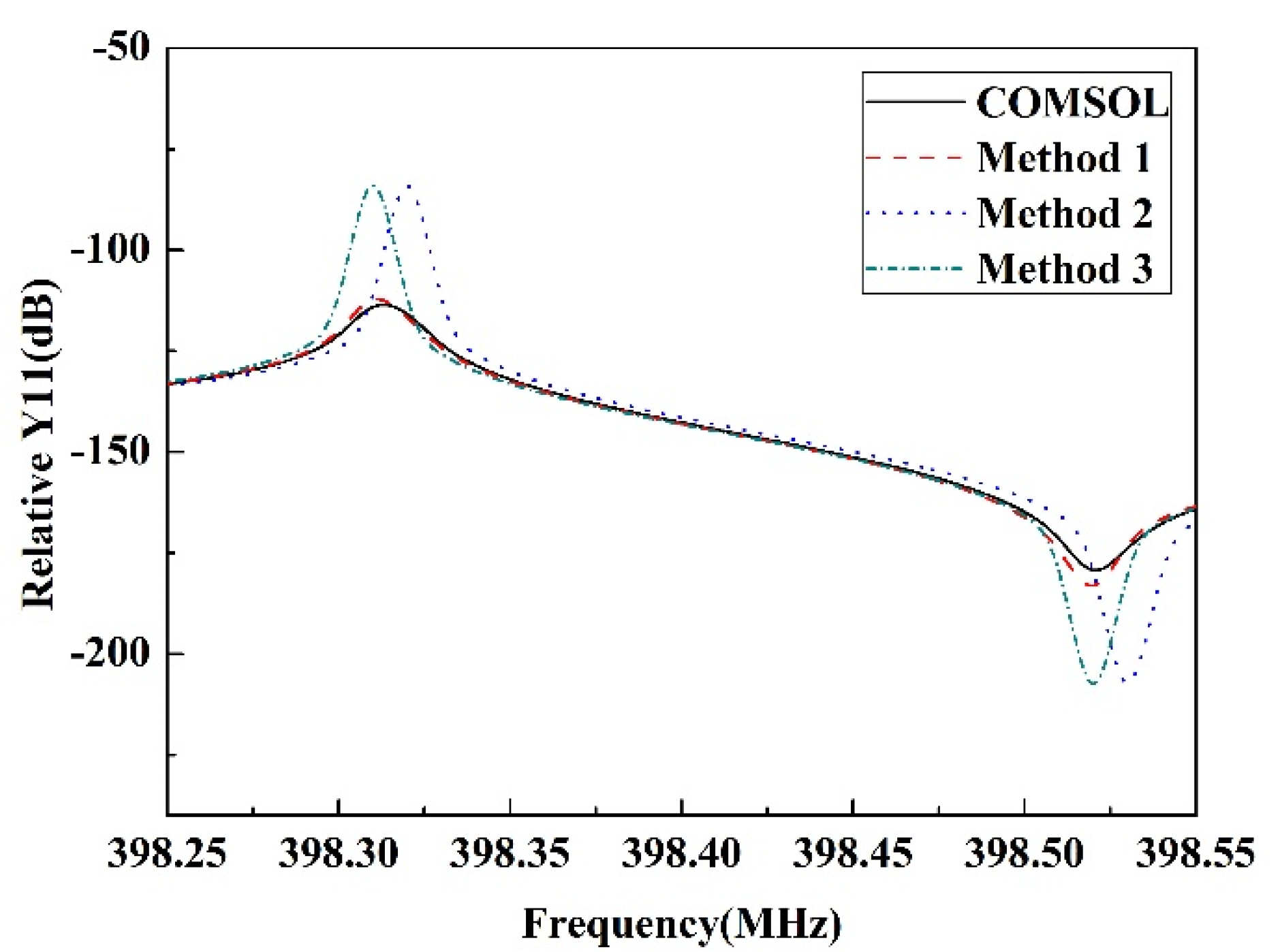
After the calculation, three groups of COM parameters were obtained. Then, we calculated the relative admittances (Y11) by these COM parameters and COMSOL, respectively. As depicted in Figure 3, the Y11 calculated by the first group of COM parameters, extracted by the method 1, is in the closest correspondence to the COMSOL calculating Y11. The slight difference is caused by the PML, which introduces additional attenuation in the calculation [25]. Thus, it could be concluded that our proposed extraction method holds excellent characteristics of higher accuracy and more efficiency simultaneously.

4. Extraction Results

In order to examine the proposed method, we have extracted the COM parameters of some common SAW substrate. They were ST quartz, ST-25°X quartz and Y-51.25°Z LiTaO3. In this section, the reference plane of coupled-mode coefficients is located at the point for Arg(α) = 0°.

4.1. ST Quartz

We considered infinitely long IDTs on the ST quartz substrate, where the pitch of IDT was p = 3.932 µm, the aluminum thin film thickness was h = 160 nm, the finger width to pitch ratio was m/p= 0.5. The material constants were taken from ref. [24]. Table 3 shows our extracted COM parameters, measured [23] and calculated values [26]. It is apparent that our results of v, αn, Cst, agree well with the measured ones, where the Cst is defined as in [23]. On the other hand, the κp is larger than the measured value, but close to the calculated value in ref. [26].

4.2. ST-25°X Quartz

We considered infinitely long IDTs on the ST-25°X quartz substrate, where p = 10 µm, h = 0.2 µm and m/p= 0.5. The material constants were also taken from ref. [24]. Table 4 shows our extracted COM parameters, measured and calculated values [27]. Excepted for normalized transduction coefficient α λ / ω C λ and static capacitance Cn, our extracted results agree better with the measured ones [27], than the calculated ones.

4.3. Y-51.25°Z LiTaO3

We considered infinitely long IDTs on the Y-51.25°Z LiTaO3 substrate, where p = 8 µm, h = 0.2 µm and m/p= 0.5. The material constants were taken from ref. [28]. Table 4 shows our extracted COM parameters, measured and calculated values [27]. Clearly, all of our extracted parameters agree better with the measured ones [27] than the calculated ones.
From Table 3, Table 4 and Table 5, it is confirmed that the difference between our extracted parameters and the measured ones [23] is slightly large for ST quartz compared with the ST-25°X quartz and the Y-51.25°Z LiTaO3 substrates. This seems to be due to the fact that the measured parameters are extracted by fitting the input admittance characteristics of a one-port SAW resonator with 25-electrode pairs and 100-wavelength aperture width [23]. Therefore, the finite IDT period, the finite aperture width, and the residual parasitics (such as resistance of busbar, which are not considered in our theoretical model) influence the measured values.

5. Conclusions

In this paper, we propose a simple and fast method to extract accurate COM parameters for designing SAW devices. It is based on the FEM and combines the stationary analysis with modal analysis. We have made a comprehensive comparison between the proposed method and the other two existing methods. Results show that the proposed method holds higher accuracy and more efficiency than the other FEM-based methods. We have also examined the proposed method by extracting COM parameters of some common SAW substrates (ST quartz, ST-25°X quartz and Y-51.25°Z LiTaO3), and compared our extracted results with those reported in the other studies. Results show that the extracted COM parameters by the proposed method are in an excellent agreement with the reported values in the other literatures, which implies that the method can be utilized in the practical design of SAW devices.

Author Contributions

Conceptualization, X.M., H.L., P.C. and X.J.; methodology, X.M.; formal analysis, H.L.; data curation, X.M.; writing, review and editing, X.M.; supervision, X.J. All authors have read and agreed to the published version of the manuscript.

Funding

This work was supported by the National Natural Science Foundation of China under Grant 52075339.

Institutional Review Board Statement

Not applicable.

Informed Consent Statement

Not applicable.

Data Availability Statement

Not applicable.

Conflicts of Interest

The authors declare no conflict of interest.

References

  1. Hashimoto, K. Advances in RF SAW devices: What are demanded? In Proceedings of the 2016 IEEE European Frequency and Time Forum, York, UK, 4–7 April 2016. [Google Scholar] [CrossRef]
  2. Ji, X.; Fan, Y.; Qi, H.; Chen, J.; Han, T.; Cai, P. A wireless demodulation system for passive surface acoustic wave torque sensor. Rev. Sci. Instrum. 2014, 85, 125001. [Google Scholar] [CrossRef] [PubMed]
  3. Ji, X.; Fan, Y.; Chen, J.; Han, T.; Cai, P. Passive wireless torque sensor based on surface transverse wave. IEEE Sens. J. 2016, 16, 888–894. [Google Scholar] [CrossRef]
  4. Shi, R.; Zhang, C.; Han, T.; Chen, J. Application of SAW RFID in the inspection management of aerodrome lights. In Proceedings of the 2014 IEEE International Ultrasonics Symposium, Chicago, IL, USA, 3–6 September 2014. [Google Scholar] [CrossRef]
  5. Mitchell, R.F.; Reilly, N.H.C. Equivalence of δ-function and equivalent-circuit models for interdigital acoustic-surface-wave transducers. Electron. Lett. 1972, 8, 329–331. [Google Scholar] [CrossRef]
  6. Kojima, T.; Kimio, S. An analysis of an equivalent circuit model for an interdigital surface-acoustic-wave transducer. Jpn. J. Appl. Phys. 1988, 27, 163. [Google Scholar] [CrossRef]
  7. Plessky, V.; Julius, K. Coupling-of-modes analysis of SAW devices. Int. J. High Speed Electron. Syst. 2000, 10, 867–947. [Google Scholar] [CrossRef]
  8. Wang, W.; Plessky, V.; Wang, H.; Wu, H.; Shui, Y. Optimization of STW Resonator by Using FEM/BEM. In Proceedings of the 2006 IEEE Ultrasonics Symposium, Vancouver, BC, Canada, 2–6 October 2006. [Google Scholar] [CrossRef]
  9. Abbott, B.P.; Hartmann, C.S.; Malocha, D.C. A coupling-of-modes analysis of chirped transducers containing reflective electrode geometries. In Proceedings of the 1989 IEEE Ultrasonics Symposium, Chicago, IL, USA, 3–6 October 1989. [Google Scholar] [CrossRef]
  10. Plessky, V. SAW impedance elements. IEEE Trans. Ultrason. Ferroelectr. Freq. Control 1995, 42, 870–875. [Google Scholar] [CrossRef]
  11. Endoh, G.; Hashimoto, K.Y.; Yamaguchi, M. Surface Acoustic Wave Propagation Characterisation by Finite-Element Method and Spectral Domain Analysis. Jpn. J. Appl. Phys. 1995, 34 Pt 1, 2638–2641. [Google Scholar] [CrossRef]
  12. Harma, S.; Victor, P. Extraction of frequency-dependent reflection, transmission, and scattering parameters for short metal reflectors from FEM-BEM simulations. IEEE Trans. Ultrason. Ferroelectr. Freq. Control 2008, 55, 883–889. [Google Scholar] [CrossRef] [PubMed]
  13. Tikka, A.C.; Al-Sarawi, S.F.; Abbott, D. SAW parameter extraction using Finite Element Analysis. Sch. Discip. 2007, 137, 593–594. [Google Scholar] [CrossRef] [Green Version]
  14. Hugo, C.; Pascal, N.; Gudrun, B.; Ayech, B. Analysis of the sensitivity to pressure and temperature of a membrane based SAW sensor. Int. J. Smart Nano Mater. 2017, 8, 95–109. [Google Scholar] [CrossRef] [Green Version]
  15. An, Y.; Hao, W.; Liu, J.; He, S. Effect of electrode width on the sensitivity of the surface acoustic wave detector in a GC/SAW. In Proceedings of the 2017 Symposium on Piezoelectricity Acoustic Waves and Device Applications (SPAWDA), Chengdu, China, 27–30 October 2017. [Google Scholar] [CrossRef]
  16. Huang, Y.; Bao, J.; Tang, G.; Omori, T.; Hashimoto, K. Influence of Coupling Between Rayleigh and SH SAWs on Rotated Y -Cut LiNbO3 to Their Propagations. IEEE Trans. Ultrason. Ferroelectr. Freq. Control 2018, 65, 1905–1913. [Google Scholar] [CrossRef] [PubMed]
  17. Huang, Y.; Bao, J.; Zhang, B.; Omori, T.; Hashimoto, K. Parameter extraction of coupling-of-modes equations including coupling between two surface acoustic waves on SiO2/Cu/LiNbO3 structures. Jpn. J. Appl. Phys. 2018, 57, 07LD13. [Google Scholar] [CrossRef]
  18. Shaposhnikov, K.; Manfred, K.; Pascal, N. Fast full-FEM computation of COM parameters Application to multilayered SAW structures. In Proceedings of the 2014 IEEE International Ultrasonics Symposium, Chicago, IL, USA, 3–6 September 2014. [Google Scholar]
  19. Hao, W.; Liu, J.; Liang, Y.; He, S. Mass sensitivity optimization of a surface acoustic wave sensor incorporating a resonator configuration. Sensors 2016, 16, 562. [Google Scholar] [CrossRef] [PubMed] [Green Version]
  20. Karim, D.; Ballandras, S.; Laroche, T.; Wagner, K.; Perois, X. Finite element analysis in combination with perfectly matched layer to the numerical modeling of acoustic devices in piezoelectric materials. Appl. Math. 2013, 4, 64–71. [Google Scholar] [CrossRef] [Green Version]
  21. Hofer, M.; Finger, N.; Kovacs, G.; Schoberl, J.; Zaglmayr, S.; Langer, U.; Lerch, R. Finite-element simulation of wave propagation in periodic piezoelectric SAW structures. IEEE Trans. Ultrason. Ferroelectr. Freq. Control 2006, 53, 1192–1201. [Google Scholar] [CrossRef] [PubMed]
  22. Hashimoto, K.; Julius, K.; Martti, M.S. Fast determination of coupling-of-modes parameters based on strip admittance approach. In Proceedings of the 1999 IEEE Ultrasonics Symposium, Caesars Tahoe, NV, USA, 17–20 October 1999. [Google Scholar] [CrossRef]
  23. Wu, T.; Wang, S.; Chen, Y.; Wu, T.; Chang, P. Inverse determination of coupling of modes parameters of surface acoustic wave resonators. Jpn. J. Appl. Phys. 2002, 41, 6610. [Google Scholar] [CrossRef]
  24. Shimizu, Y.; Yamamoto, Y. SAW propagation characteristics of complete cut of quartz and new cuts with zero temperature coefficient of delay. In Proceedings of the 1980 Ultrasonics Symposium, Boston, MA, USA, 5–7 November 1980. [Google Scholar] [CrossRef]
  25. Koskela, J.; Victor, P.; Martti, M. SAW/LSAW COM parameter extraction from computer experiments with harmonic admittance of a periodic array of electrodes. IEEE Trans. Ultrason. Ferroelectr. Freq. Control 1999, 46, 806–816. [Google Scholar] [CrossRef] [PubMed]
  26. Mc Cormack, B.; Dermot, G.; Margaret, O. Modeling of surface acoustic wave strain sensors using coupling-of-modes analysis. IEEE Trans. Ultrason. Ferroelectr. Freq. Control 2011, 58, 2461–2468. [Google Scholar] [CrossRef] [PubMed]
  27. Thorvaldsson, T.; Abbott, B. Low loss SAW filters utilizing the natural single phase unidirectional transducer (NSPUDT). In Proceedings of the 1990 IEEE Symposium on Ultrasonics, Honolulu, HI, USA, 4–7 December 1990. [Google Scholar] [CrossRef]
  28. Kovacs, G.; Anhom, M.; Engan, H.; Visintini, G.; Ruppel, C. Improved material constants for LiNbO3 and LiTaO3. In Proceedings of the 1990 IEEE Symposium on Ultrasonics, Honolulu, HI, USA, 4–7 December 1990. [Google Scholar] [CrossRef]
Figure 1. The schematic of COM model for the IDT.
Applsci 12 04547 g001
Figure 2. Primitive cell of an infinitely periodic grating.
Applsci 12 04547 g002
Figure 3. Relative admittances calculated using extracted COM parameters and COMSOL.
Applsci 12 04547 g003
Table 1. The boundary conditions of the stationary analysis.
BoundaryMechanical
Boundary Conditions
Electrical
Boundary Conditions
ΓT (top of air)FreeZero charge
ΓA (air-solid interfaces)FreeContinuity
Γ+, Γ (±electrode-solid interfaces)FreeVΓ+ − VΓ− = ΔV
ΓB (bottom of substrate)FixedZero charge
ΓL, ΓR (left and right boundaries)Periodic continuity boundary condition
ΓF, ΓE (front and back boundaries)Periodic continuity boundary condition
Table 2. The boundary conditions for the three different methods.
BoundaryMechanical Boundary ConditionsElectrical Boundary Conditions
ΓTFreeZero charge
ΓAFreeContinuity
ΓBFixedGround
Γ+, ΓFree1: V = 0 (SC); D i · n i d S = 0 (OC)
2 and 3: VΓ+ = 1V; VΓ− = 0V
ΓL, ΓR1 and 2: Periodic continuity boundary condition
3: Floquet boundary condition: kx = (1 + Δ)k0
ΓF, ΓEPeriodic continuity boundary condition
Notice: 1, 2, 3 represent methods 1, 2 and 3.
Table 3. COM parameters for ST quartz substrate.
COM ParameterMeasured Value [23]Calculated Value [26]Our Results
v (m/s)314631523143
κp (= κλ)−0.015−0.021−0.023
Arg(κ) [deg]0
αn (f0)( 1 / Ω λ )2.71 × 10−42.84 × 10−42.85 × 10⁻⁴
Cst (pF)1.951.921.953
Table 4. COM parameters for ST-25°X quartz substrate.
COM ParameterMeasured Value [27]Calculated Value [27]Our Results
v (m/s)3239.73242.13240.7
κp (= κλ)0.005840.00490.00575
Arg(κ) [deg]95.68103.1797.96
α λ / ω C λ 0.02140.02050.0224
Cn (pF/m)50.7749.2749.11
Table 5. COM parameters for Y-51.25°Z LiTaO3 substrate.
COM ParameterMeasured Value [27]Calculated Value [27]Our Results
v (m/s)3199.83206.73200.23
κp (= κλ)0.00980.01060.0106
Arg(κ) [deg]101.6113.91100.4
α λ / ω C λ 0.04550.04070.0459
Cn (pF/m)455446.6447.68
Publisher’s Note: MDPI stays neutral with regard to jurisdictional claims in published maps and institutional affiliations.