Abstract
A ball screw is a mechanical part that converts rotational motion into translational motion, but when it receives an excessive axial load, permanent deformation occurs inside. As ball screws are mostly used for precise driving, permanent deformation has a fatal effect on the operation of the system. As this permanent deformation mostly occurs on the contact surface between the ball and other parts, it is necessary to observe the change of internal stress caused by the contact of the parts in order to determine whether permanent deformation occurs. Theoretical calculations or finite element analysis (FEA) are mainly used for the analysis of rotating parts, but existing methods have difficulty in observing stress changes occurring on the narrow contact surface of ball screws. In this paper, a new FEA model that can efficiently estimate the stress caused by internal contact inside the ball screw is presented. This model is a synthetic model that applies theoretical calculation results to a 3D FEA model. Factors derived by theoretical calculation include the shape of the contact surface where the ball and other parts meet and the contact pressure at the contact surface, which were derived by a method based on Hertz contact theory. As a result of observing the internal stress distribution of the ball screw estimated by the model, it was confirmed that the shape was similar to that of the actual stress distribution and, compared with the analysis results of other conventional methods conducted with the same mesh shape, the results of the model presented in this paper were more valid.
1. Introduction
A ball screw is a mechanical part that converts rotational motion into translational motion. As shown in Figure 1, ball screws are composed of a shaft, a nut, a circulation part, balls, etc. It is designed in such a structure that the ball rolls between the grooves of threaded shaft and nut and returns to its initial position through the circulation part. As the ball screw adopts rolling friction and not sliding friction, it can have very low friction loss and high efficiency. These characteristics of ball screws are the reason they are used in precision mechanical devices such as artificial respirators, precision positioning tables, machine tools, and guided missiles. However, when an excessive axial load is applied, the narrow contact surface between the ball and the ball groove is dented, leaving permanent deformation, which is fatal to the ball screw requiring precise driving [1,2]. To determine whether such permanent deformation occurs, as it is necessary to know the change of the internal stress caused by the contacts of the components, many studies are being conducted to estimate this.
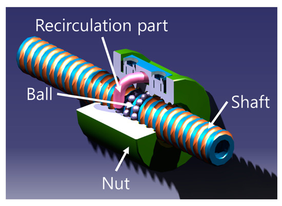
Figure 1.
Ball screw configuration.
The following are studies analyzing the rotating parts, and it was determined whether applied methodologies can observe stress changes occurring on the contact surface of the ball screw. Research to analyze rotating parts is divided into three main categories. The first is the theoretical method, the second is the FEA (Finite Element Analysis), and the third is the synthetic method that applies both theoretical methods and FEA. The study of Wei and Lin [3] and Lazović and Milović [4] could theoretically represent the magnitude of the load applied to the contact surface of the rotating parts from an external force, but there was a limitation that the internal stress distribution could not be expressed. Du et al. [5] conducted a 2D FEA considering the adhesive force be-tween two contacting objects. However, as one of the two contacting objects was analyzed as a rigid flat surface, it is difficult to apply to the case of a ball screw whose both contacting objects are soft bodies and both contacting surfaces are curved. By applying the Laboratoire de Génie Mécanique de Toulouse model in Daidié et al. [6] and two nodes calculating physical proper-ties in Azianou et al. [7], load distribution and displacement were derived by FEA that replaced the ball between the inner and outer rings of the bearing. These methodologies were effective in expressing the rough behavior of the bearing, but still have difficulty in analyzing the stress distribution from the contact load. There are studies that have conducted FEA considering the shape and mesh of all ball bearing components, but this is a method that can only be applied to a specific shape when the degree of freedom of the ball is considerably limited [8,9]. There are studies deriving the friction torque, rotational speed, and load applied to the contact surface through dynamic analysis of the ball screw, but there are also limits to deriving the stress distribution by the load applied to the contact surface [10,11,12].
There are various methodologies that can estimate the load applied to the contact surface of rotating parts and express the approximate movement. However, overall, all were limited in estimating how the stress distribution of the contact components changes inside the rotating parts that have complex shapes such as ball screws. This paper presents a new model that could observe the stress change of the internal contact components of the ball screw by applying both the theoretical method and the FEA. The components of the ball screw were separated one by one, and each FEA model was created and solved. To this end, the shape of the contact surface and the pressure applied to the contact surface were derived by a method based on Hertz contact theory. The shape of the contact surface appeared elliptical and was applied to the 3D modeling of ball screw. The contact pressure was derived as a formulation that gradually weakens from the center to the edge, and was applied to an FEA model in the form of an APDL code.
In general, there are two FEA models most frequently used to observe changes in contact surfaces: a model to which node connecting is applied in the mesh generation step and a model to which contact conditions are added to the contact surface. This paper compares the results of the model to which the contact condition is applied with the analysis results of the presented model and confirms that the presented model has more valid results. In the case of ball screws, application of node connecting is not appropriate because the contact surface before load is very narrow and the size change of the contact surface after load is large. Therefore, a model with node connecting was not built.
2. Theoretical Analysis
Theoretical analysis includes all the processes of deriving the shape of the contact surface and the formulation of contact pressure generated on the contact surface. The assumptions applied in this study are described below.
2.1. Assumptions
To apply the Hertz contact theory, only the normal force was considered without friction in the contact, and the ball screw operates only within the range of elastic behavior [13].
In the actual ball screw interior case, there will be highly loaded balls and low loaded balls depending on the external environment. However, we assumed all balls received the same load in this paper.
There are two representative approaches for deriving the pressure applied to the contact surface. The first is the Hertz contact theory and the second is the method applying Elastohydrodynamic. When Elastohydrodynamic is applied, a more realistic contact pressure can be derived with the consideration of the lubricating film effect [14], but in this paper, the pressure applied to the contact surface was derived by considering only the simpler Hertz contact theory.
2.2. Theoretical Study of Ball Screw
Please read this subsection looking at the nomenclature section on the back.
In the stationary state, each ball in the ball screw has contact surfaces in a total of four directions, but when an axial load is applied to the nut, each ball can be viewed as a two-force member having two contact points between the nut and the shaft. Axial load means the load that is applied to the axial direction of the ball screw. This is shown in Figure 2, and the normal load generated at the contact surface of the ball and the ball groove can be expressed as follows [15]:
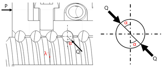
Figure 2.
Normal contact load direction of ball screw.
The shape of the contact surface can be derived from the contact theory according to the magnitude of normal load , and it appears in an elliptical shape as shown in Figure 3. There were several formulas for calculating the semi major axis and the semi minor axis , which are dimensional information that can define the shape of an ellipse [16,17,18]. However, none of them could be directly applied for the case of ball screws with spiral ball grooves. Accordingly, D. Olaru et al. [19] developed the study of L. Houpert [17] to be applicable to ball screws and created a new model, which can be expressed as follows:
here, the variable with the subscript bs means the variables related to the contact between the ball and the shaft, and the variables with subscript bn mean the variables related to the contact between the ball and the nut. In the above equation, to calculate the semi minor and major axis of the contact ellipse, it can be confirmed that the equivalent radius in the rolling direction , the transversal equivalent radius , the radii ratio , and the equivalent elastic modulus is needed. This can be expressed as follows:
here, means the curvature parameter, and a value between 0.515 and 0.54 is generally used [13,17,19].
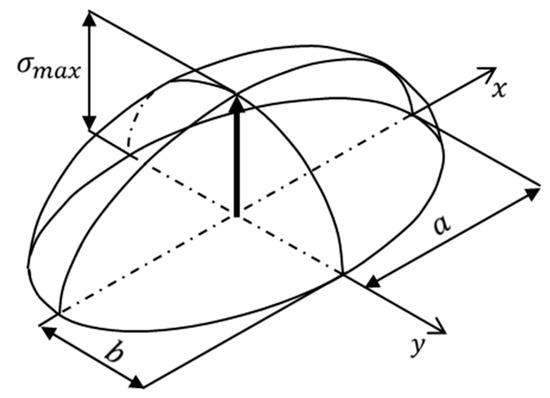
Figure 3.
Stress distribution on contact ellipse.
Assuming that the ball screw is operated within the range of elastic behavior of the material, the pressure applied to the contact surface can be expressed as shown in Figure 3. It appears in the form of a Hertzian pressure where the value approaches to 0 as it draws closer to the edge from the center of the contact surface. The maximum contact pressure and partial contact pressure σ can be expressed as follows [17]:
3. FEA
As mentioned earlier, the equations in Section 2 will be used to obtain the input values of the new FEA model. In this section, the process of applying the equations derived in Section 2 to the FEA model will be listed with an example. Additionally, the analysis results of the new model will be compared with the analysis results of the model to which the contact conditions are applied. The contact theory based models exist separately for each component, but the model to which the contact condition is applied has the difference that the two contact components are included in the same model.
3.1. Subject Configuration and Material Property
The ball screw to which the FEA is applied is a tube type as shown in Figure 4. The shape information of it is written in Table 1, and the mechanical properties are shown in Table 2.
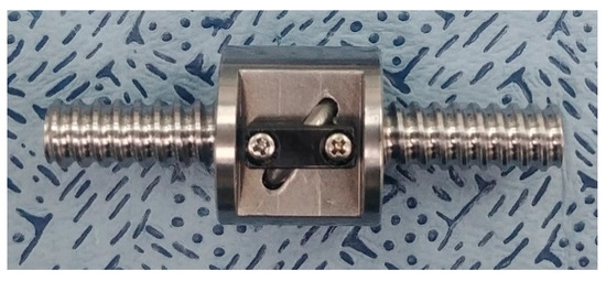
Figure 4.
Analysis subject.

Table 1.
Geometric parameters of ball screw.

Table 2.
Material properties.
If the ball screw receives an axial load of 100 N, the maximum contact pressure calculated by Equations (14) and (15) is shown in Table 3, and it can be seen that the largest contact pressure occurs at the contact surface between the ball and shaft.

Table 3.
Maximum compressive stress.
3.2. Boundary Conditions
The material of the shaft and the nut is the same, but the contact pressure between the ball and the shaft is the largest, so the FEA was applied only to the shaft and the ball. Before proceeding with the FEA, the dimensions of the contact ellipse were derived by referring to the equations shown in Equations (2)–(5), and it is expressed in Table 4. As shown in Figure 5, the shape of the contact ellipse surface was modeled as the shape of the contact is projected on the shaft and the ball in the normal load direction. In addition, 3D modeling was used on the shaft, leaving only one lead up and down at the point where the contact surface was modeled for reducing the data processing requirements.

Table 4.
Parameters of contact ellipse.
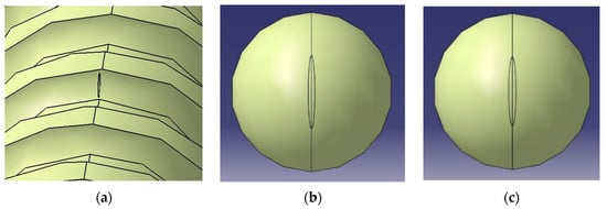
Figure 5.
Contact ellipse configuration: (a) Shaft; (b) Ball (ball shaft contact); and (c) Ball (ball nut contact).
3.2.1. Contact Theory Based Model
In the case of a contact theory based model, local coordinate systems with the center of the contact surface as the origin were created on the contact surface, and then the con-tact pressure shown in Equations (16) and (17) were written in APDL code and entered. As for boundary conditions, as shown in Figure 6, the cut surface of the shaft was fixed and, considering that the ball has a symmetrical shape, the degree of freedom of the nodes were limited so that the nodes at circumference of the three directions (X, Y, and Z) could only move in the circumferential direction.
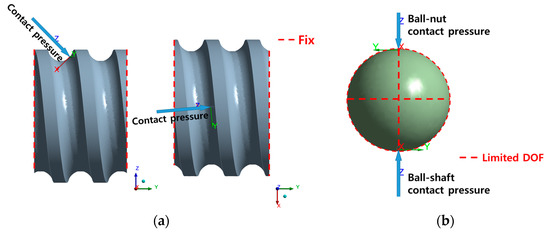
Figure 6.
Boundary conditions of contact theory based model: (a) Shaft; (b) Ball.
3.2.2. Contact Condition Applied Model
In the case of a model to which the contact condition was applied, the no separation contact condition, in which two contact surfaces could slide without friction, was applied. Formulation, which is mainly used in contact conditions, includes augmented Lagrange, pure penalty, normal Lagrange, and MPC, but normal Lagrange and MPC were excluded because they derive only the analysis result of one of the two components in contact. Therefore, only the FEA models to which augmented Lagrange and pure penalty were applied were separately built. As shown in Figure 7, the contact pressure derived in Section 2 was applied to the surface where the ball is in contact with the nut, and the cut surface of the shaft was fixed [20,21].
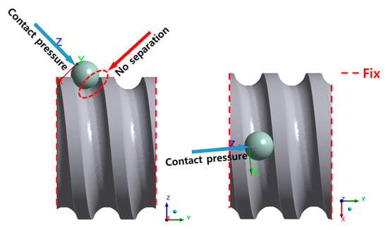
Figure 7.
Boundary conditions of contact condition applied model.
3.3. Results and Discussion
The mesh was generated in a tetrahedral shape, and to reduce the dependency on the mesh, theory based models were iteratively solved by decreasing the mesh size and increasing the number of mesh until there was no change in the equivalent stress. As shown in Table 5 and Figure 8 and Figure 9, it could be observed that the maximum equivalent stress value vibrates and the shape of stress distribution is stable from the mesh size of Type 3–5. Therefore, the mesh size of Type 4 was adopted to FEA model. In addition, the results derived from the model composed of Type 4 mesh size were determined as the final analysis results of theory based FEA model. The two cut surfaces shown in Figure 8 and Figure 9 show the cut surface in the semi major axis direction and the semi minor axis direction of the components, respectively. As shown in Figure 10, the shaft has 969,599 nodes and 4,837,708 elements, and the ball has 135,908 nodes and 663,794 elements.

Table 5.
Results of mesh dependency test.
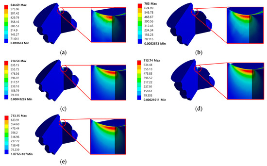
Figure 8.
Equivalent stress (MPa) results of contact theory based model (shaft): (a) Type1; (b) Type2; (c) Type3; (d) Type4; and (e) Type5.
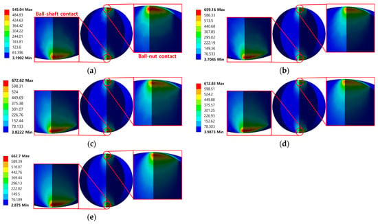
Figure 9.
Equivalent stress (MPa) results of contact theory based model (ball): (a) Type1; (b) Type2; (c) Type3; (d) Type4; and (e) Type5.
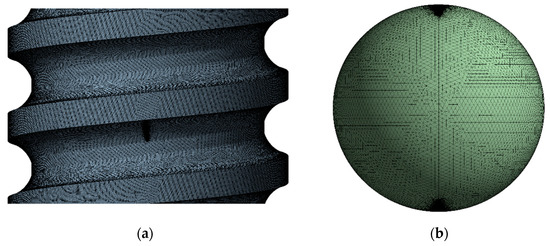
Figure 10.
Mesh configuration: (a) Shaft; (b) Ball.
The analysis of the model to which the contact conditions were applied was performed with Type 4 mesh size for comparison in the same criteria, and the results are shown in Figure 11. Figure 11 also shows both the semi major axis and the semi minor axis cut surface of the analysis results as in Figure 8 and Figure 9. As a result of solving models composed of pure penalty or augmented Lagrange, both maximum stress recorded very high stress values compared to the results of contact theory based models. In addition, the internal stress estimated by the contact pressure should have a symmetrical shape in which the stress is concentrated under the center of the contact surface, and the stress should weaken as it deviates from the point. This shape can be observed in the results of the contact theory based model shown in Figure 8 and Figure 9. However, in the results of the model to which the contact condition is applied, shown in Figure 11, it can be observed that greater stress was generated at points farther from the center of the contact surface. As a result of observing the shape of the contact pressure, as shown in Figure 12, it can be confirmed that the stress is concentrated in a very narrow area, which was determined to be the cause of excessive stress. The contact theory based model directly inputs the contact pressure to the contact surface, but the model to which the contact condition is applied seems to have caused singularity in the process of calculating and applying contact pressure using contact formulations. These comparison results prove that the contact theory based model exhibits more valid results even when using the same mesh size [18,22].
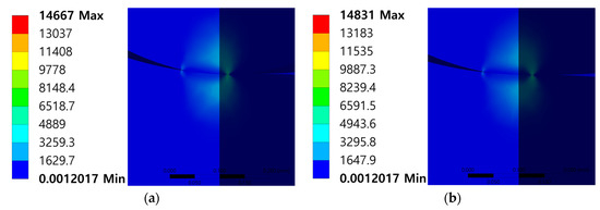
Figure 11.
Equivalent stress (von Mises) results of contact condition applied model: (a) Pure penalty; (b) Augmented Lagrange.
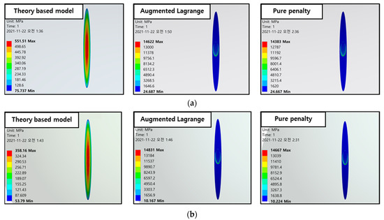
Figure 12.
Equivalent stress (MPa) comparison on contact surface: (a) Shaft; (b) Ball.
4. Conclusions and Future Works
In this paper, a new methodology that can observe how the stress in ball screws changes in an environment in which they will be used was presented.
First, the contact surface shape and contact pressure between ball screw parts were theoretically analyzed through several precedent studies based on the Hertz contact theory. For theoretical analysis, the only equation that can express the shape of the contact surface and the distribution of contact stress where the ball and the screw meet each other was used to derive the shape of the elliptical contact surface and the pressure distribution on the contact surface. Additionally, this methodology has never been exploited in conventional ball screw analysis research results. The shape of the contact surface was added in the 3D modeling stage, and the pressure distribution on the contact surface was written in APDL code and applied to FEA model. It was confirmed that the stress distribution inside the ball screw derived from the analysis result of the model made by this process was similar to the actual stress distribution. In addition, when compared with the results of the commonly used model to which the contact condition is applied, it was confirmed that the contact theory based model showed more valid results even in the same mesh size.
The methodology presented in this study does not consider friction in order to apply the Hertz contact theory, and it can only be used when the load applied to the ball screw causes the elastic behavior of the material alone. It will be interesting to develop this study with the consideration of a realistic contact pressure considering Elastohydrodynamics or a material plasticity. In addition, in this paper, it was not considered that the components of the ball screw were heat-treated. It is also recommended to build an analysis model that considers changes in material properties of heat-treated ball screw components for surface hardening.
Author Contributions
Conceptualization, G.-H.S.; methodology, G.-H.S.; software, G.-H.S.; validation, G.-H.S.; formal analysis, G.-H.S.; investigation, G.-H.S.; resources, J.-W.H.; data curation, G.-H.S.; writing—original draft preparation, G.-H.S.; writing—review and editing, J.-W.H.; visualization, G.-H.S.; supervision, J.-W.H.; project administration, J.-W.H.; and funding acquisition, J.-W.H. All authors have read and agreed to the published version of the manuscript.
Funding
This research was supported by the MSIT (Ministry of Science and ICT), Korea, under the Grand Information Technology Research Center support program (IITP-2020-2020-0-01612) supervised by the IITP (Institute for Information & communications Technology Planning & Evaluation).
Institutional Review Board Statement
Not applicable.
Informed Consent Statement
Not applicable.
Data Availability Statement
Not applicable.
Conflicts of Interest
The authors declare no conflict of interest.
Nomenclature
| The number of balls between shaft and nut | |
| Axial load | |
| Normal load | |
| Contact angle | |
| Lead angle | |
| Semi major axis of contact ellipse | |
| Semi minor axis of contact ellipse | |
| Equivalent radius in the rolling direction | |
| Transversal equivalent radius | |
| Radii ratio | |
| Ball diameter | |
| Pitch circle diameter of balls | |
| Curvature parameter for the shaft race | |
| Curvature parameter for the nut race | |
| Equivalent elastic modulus | |
| Elastic modulus of shaft | |
| Elastic modulus of ball | |
| Elastic modulus of nut | |
| Poisson’s ratio of shaft | |
| Poisson’s ratio of ball | |
| Poisson’s ratio of nut | |
| Max contact pressure | |
| Local contact pressure |
References
- Precision Machinery & Parts e-Project Team. Ball Screw Guide Introduction; NSK Ltd.: Tokyo, Japan, 2016. [Google Scholar]
- Bogdan, L.; Telea, D.; Barbu, Ş. Management and motion control of ball screw actuators applied in the robotic structures. Robot. Manag. 2012, 17, 14–17. [Google Scholar]
- Wei, C.C.; Lin, J.F. Kinematic analysis of the ball screw mechanism considering variable contact angles and elastic deformations. J. Mech. Des. 2003, 125, 717–733. [Google Scholar] [CrossRef]
- Lazović, T.; Milović, S.V.L. Contact stresses and deformations in thrust ball bearing. Mach. Des. 2018, 10, 85–92. [Google Scholar]
- Du, Y.; Chen, L.; McGruer, N.E.; Adams, G.G.; Etsion, I. A finite element model of loading and unloading of an asperity contact with adhesion and plasticity. J. Colloid Interface Sci. 2007, 312, 522–528. [Google Scholar] [CrossRef] [PubMed]
- Daidié, A.; Chaib, Z.; Ghosn, A. 3D simplified finite elements analysis of load and contact angle in a slewing ball bearing. J. Mech. Des. 2008, 130, 082601. [Google Scholar] [CrossRef]
- Azianou, A.E.; Debray, K.; Bolaers, F.; Chiozzi, P.; Palleschi, F. Modeling of the behavior of a deep groove ball bearing in its housing. J. Appl. Math. Phys. 2013, 1, 45–50. [Google Scholar] [CrossRef]
- Zhaoping, T.; Jianping, S. The contact analysis for deep groove ball bearing based on ANSYS. Procedia Eng. 2011, 23, 423–428. [Google Scholar] [CrossRef] [Green Version]
- Šulka, P.; Sapietová, A.; Dekýš, V.; Sapieta, M. Static structural analysis of rolling ball bearing. MATEC Web Conf. 2018, 244, 01023. [Google Scholar] [CrossRef]
- Xu, N.; Tang, W.; Chen, Y.; Bao, D.; Guo, Y. Modeling analysis and experimental study for the friction of a ball screw. Mech. Mach. Theory 2015, 87, 57–69. [Google Scholar] [CrossRef]
- Wang, Y.; Wang, W.; Zhang, S.; Zhao, Z. Investigation of skidding in angular contact ball bearings under high speed. Tribol. Int. 2015, 92, 404–417. [Google Scholar] [CrossRef]
- Oh, K.J.; Cao, L.; Chung, S.C. Explicit modeling and investigation of friction torques in double-nut ball screws for the precision design of ball screw feed drives. Tribol. Int. 2020, 141, 105841. [Google Scholar] [CrossRef]
- Jackson, R.L.; Ghaednia, H.; Lee, H.; Rostami, A.; Wang, X. Tribology for Scientists and Engineers; Springer: New York, NY, USA, 2013. [Google Scholar]
- Habchi, W.; Demirci, I.; Eyheramendy, D.; Morales-Espejel, G.; Vergne, P. A finite element approach of thin film lubrication in circular EHD contacts. Tribol. Int. 2007, 40, 1466–1473. [Google Scholar] [CrossRef]
- Luo, H.; Fu, J.; Jiao, L.; Zhao, F. Theoretical calculation and simulation analysis of axial static stiffness of double-nut ball screw with heavy load and high precision. Math. Probl. Eng. 2019, 2019, 9608794. [Google Scholar] [CrossRef]
- Greenwood, J.A. Analysis of elliptical Hertzian contacts. Tribol. Int. 1997, 30, 235–237. [Google Scholar] [CrossRef]
- Houpert, L. Numerical and analytical calculations in ball bearings. In Proceedings of the 8th European Space Mechanism and Tribology Symposium, Toulouse, France, 1 September 1999. [Google Scholar]
- Harris, T.A. Rolling Bearing Analysis, 4th ed.; John Wiley and Sons: New York, NY, USA, 2001. [Google Scholar]
- Olaru, D.; Puiu, G.C.; Balan, L.C.; Puiu, V. A new model to estimate friction torque in a ball screw system. Prod. Eng. 2006, 3, 333–346. [Google Scholar]
- ANSYS Inc. Contact Technology Guide; ANSYS Inc.: Canonsburg, PA, USA, 2004. [Google Scholar]
- ANSYS Inc. Theory Reference for the Mechanical APDL and Mechanical Applications; ANSYS Inc.: Canonsburg, PA, USA, 2009. [Google Scholar]
- Ostertag, O.; Frankovský, P.; Ostertagová, E.; Trebuňa, F. Application of the harmonic star method in photoelastic separation of principal stresses. Appl. Opt. 2016, 55, 425–431. [Google Scholar] [CrossRef] [PubMed]
Publisher’s Note: MDPI stays neutral with regard to jurisdictional claims in published maps and institutional affiliations. |
© 2022 by the authors. Licensee MDPI, Basel, Switzerland. This article is an open access article distributed under the terms and conditions of the Creative Commons Attribution (CC BY) license (https://creativecommons.org/licenses/by/4.0/).