Article

Analysis of Microtremor Exploration Application and Construction Monitoring in a Large-Diameter Shield Tunnel

1
Institute of Geotechnical Engineering, Zhejiang University of Technology, Hangzhou 310014, China
2
School of Landscape Architecture, Zhejiang A & F University, Hangzhou 311300, China
3
National Engineering Research Center for High Speed Railway Construction Technology, Central South University, Changsha 410004, China
*
Authors to whom correspondence should be addressed.
Appl. Sci. 2023, 13(1), 263; https://doi.org/10.3390/app13010263
Submission received: 30 November 2022 / Revised: 20 December 2022 / Accepted: 22 December 2022 / Published: 26 December 2022
(This article belongs to the Special Issue Evaluation and Monitoring of Geotechnical Stability)

Abstract

:
In recent years, shield tunneling has shown many advantages with the development of underground rail traffic. Geological exploration plays a significant role in tunnel engineering, and detailed geological exploration results can guide the successful construction of a tunnel. This research relies on a super large-diameter shield tunnel construction, using microtremor exploration technology to collect data onsite. Combined with a comparative analysis of the borehole surveying, the reliability of microtremor exploration technology is verified. Moreover, the monitoring result of the impact of large-diameter slurry balanced shield construction on the surrounding environment is analyzed. The results show that microtremor exploration can obtain geological details that traditional detection methods cannot obtain, which can predict the possible local geology mutation in front of the tunnel in advance. The law of surface settlement curve conforms to the Peck formula. This can be divided into five stages: micro deformation, extrusion uplift, reciprocating uplift, detachment settlement, and consolidation settlement. The surface settlement on the eccentric loads side is more prominent. The maximum pressure outside the tunnel segment appears on the lower side of the monitoring section, approximately 0.41 MPa, which will increase with the grouting pressure and become stable in five days.

1. Introduction

With the rapid construction of urban rail transit, shield tunneling has been widely used and developed in tunnel engineering. Compared with other tunnel excavation methods, shield tunneling can better adapt to various strata and has apparent advantages in ground deformation control and construction safety [1]. However, there are several problems associated with shield construction, such as the stability of the excavation face, the maintenance of the cutterhead and cutter for long-distance tunneling, and disturbance to the surrounding soil [2,3]. There is a noticeable correlation between shield construction and geological parameters. Clear geological conditions help adjust construction parameters in time to compensate for these shortcomings. Moreover, when important buildings or rivers are around the shield tunnel, it is not easy to control the stratum deformation caused by large-diameter shield tunneling [4]. In order to achieve the safety control of construction, it is necessary to study the exploration method of geological conditions and the shield’s impact on the surrounding environment. Recently, drilling, shallow seismic reflection, surface wave exploration, and other methods have been widely used to obtain shallow surface structures [5,6,7]. Geological anomalies in stratum can be reflected according to different wave velocities. Based on this theory, microtremor exploration, with its advantages of being low in cost, highly efficient, and less restricted by environmental conditions, has been widely used compared with other standard geophysical methods. Moreover, the application of high density and high frequency in a particular range makes it possible to draw a three-dimensional geological model [8,9,10]. Comprehensive geological survey results can ensure the efficiency and safety of shield construction. However, studies combining the survey results with the adjustment of construction parameters are rare.
Since the surface settlement reflects the stability degree of the surrounding ground surface and rock mass, it is essential to analyze them when excavating a large-diameter tunnel. Relying on numerical modeling, many studies have been conducted on surface settlement induced by tunneling [11,12,13,14]. However, the result of the numerical evaluation model is often less accurate than field monitoring. In recent decades, researchers have carried out a large number of case-based studies on the soil deformation law generated by shield tunneling [15,16,17,18,19]. Their research shows that, when an earth pressure balance (EPB) shield passes through different strata, the disturbance to surrounding soil is also different. The field monitoring results show that, when the shield machine reaches the monitoring section, the ground surface appears to bulge first and then settle. However, the opposite result is true under the large depth of the embedment of the tunnel [16]. There is much research on small-diameter shield tunnels; however, there is less for large ones [20,21,22]. Existing research on large-diameter shield tunnels has mainly been conducted under good geological conditions, while there are few research studies on complex geological and surrounding environmental conditions. In addition, the grouting volume and pressure are closely related to the influence of soil deformation, therefore it is necessary to monitor the grouting parameters during shield tunneling [23,24,25].
Based on the large-diameter shield tunnel construction with eccentric load on one side, the geological conditions along the shield tunneling direction are predicted in advance through the microtremor exploration system. The results are compared with the sample of traditional drilling exploration. Based on the premise that clear geological conditions guide the timely adjustment of shield tunneling parameters, the practicability and reliability of microtremor exploration are verified. The correlation between shield construction parameters and the result of geological exploration is analyzed. Field monitoring tests were conducted on the pressure of the tunnel segment and surface settlement. Moreover, surface deformation and pressure variation laws are analyzed, which provides certain engineering significance for similar projects.

2. Geological Prospecting and Field Monitoring

2.1. Project Overview

The exploration and monitored field is located in the west section shield tunnel of the Zhijiang Road water conveyance pipe gallery and road lifting project of Hangzhou, China. Hangzhou’s latitude is 30.18° N and longitude 120.10° E. The 6.3 km shield tunnel lies around the Qiantang River, Wupu River, and Shanhusha Reservoir in Hangzhou. The slope and high retaining wall are located northwest of the tunnel, resulting in a large area of unbalanced load. A super large-diameter slurry shield machine constructs the project. The minimum curvature radius of the line plane is 768 m. The maximum slope is 40 ‰, the excavation diameter of the tunnel is 15.01 m, the outer diameter of the tunnel segment is 14.5 m, the inner diameter of the tunnel segment is 13.3 m, the ring width is 2 m, and the overburden thickness is 7.8 m to 17.9 m. The range of geological exploration is between Ring 62 and 429 of this tunnel. The monitoring section of surface settlement is located at Ring 101 and 130, and the monitoring section of soil pressure outside the segment is located at Ring 101. The general plan of the shield tunnel is shown in Figure 1.

2.2. Geological and Hydrogeological Conditions

The geological prospecting team obtained geotechnical test samples by drilling in the field and then analyzed them through a series of tests. Moreover, microtremor exploration detectors were arranged at the locations of detection holes ZK082, ZK085, ZK086, and ZK093, respectively. The analysis of geological drilling exploration verified the reliability of the microtremor exploration results. The geological conditions in the interval mainly include: ①-1 gravel fill, ①-2 plain fill, (20)-a1 fully weathered argillaceous siltstone, (20)-a2 strongly weathered argillaceous siltstone, (20)-a3 moderately weathered argillaceous siltstone, (20)-c2 strongly weathered tuffaceous gravelly sandstone, and (20)-c3 moderately weathered tuffaceous gravelly sandstone. The phreatic pore aquifer in the survey scope is characterized by a shallow burial, small water volume, and significant variation. The dynamic change amplitude is generally about 1.0~2.0 m. During the survey, the measured phreatic water was 1.40 m to 5.80 m below the overburden depth. The geological profile of the monitoring section is shown in Figure 2, and the specific soil physical and mechanical parameters are shown in Table 1.

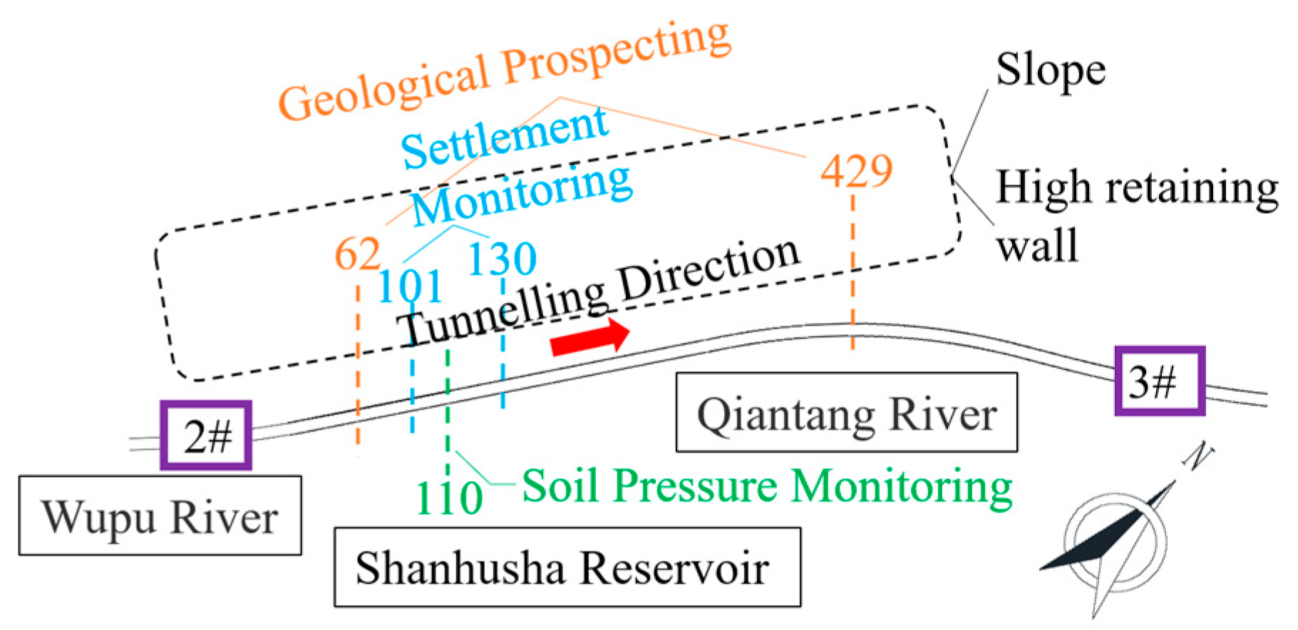
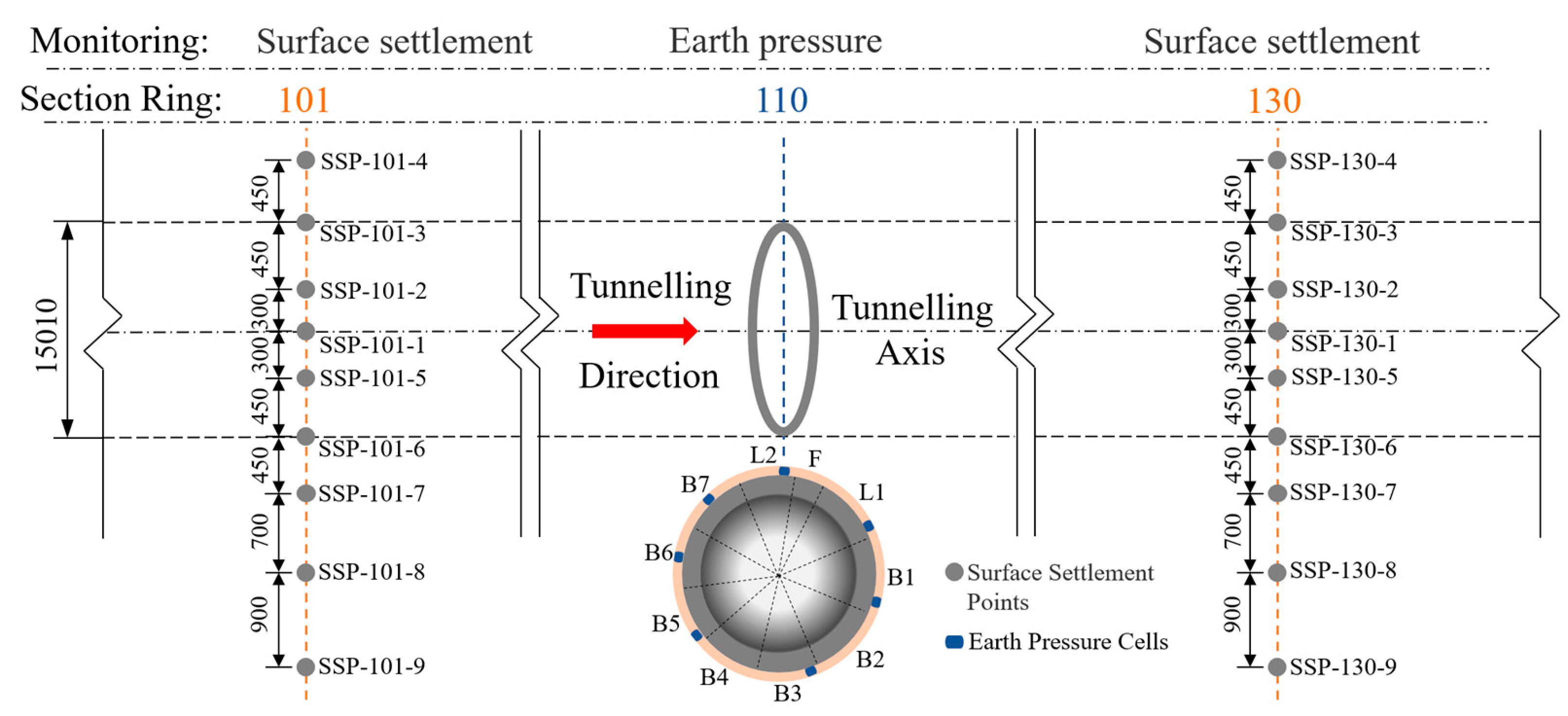
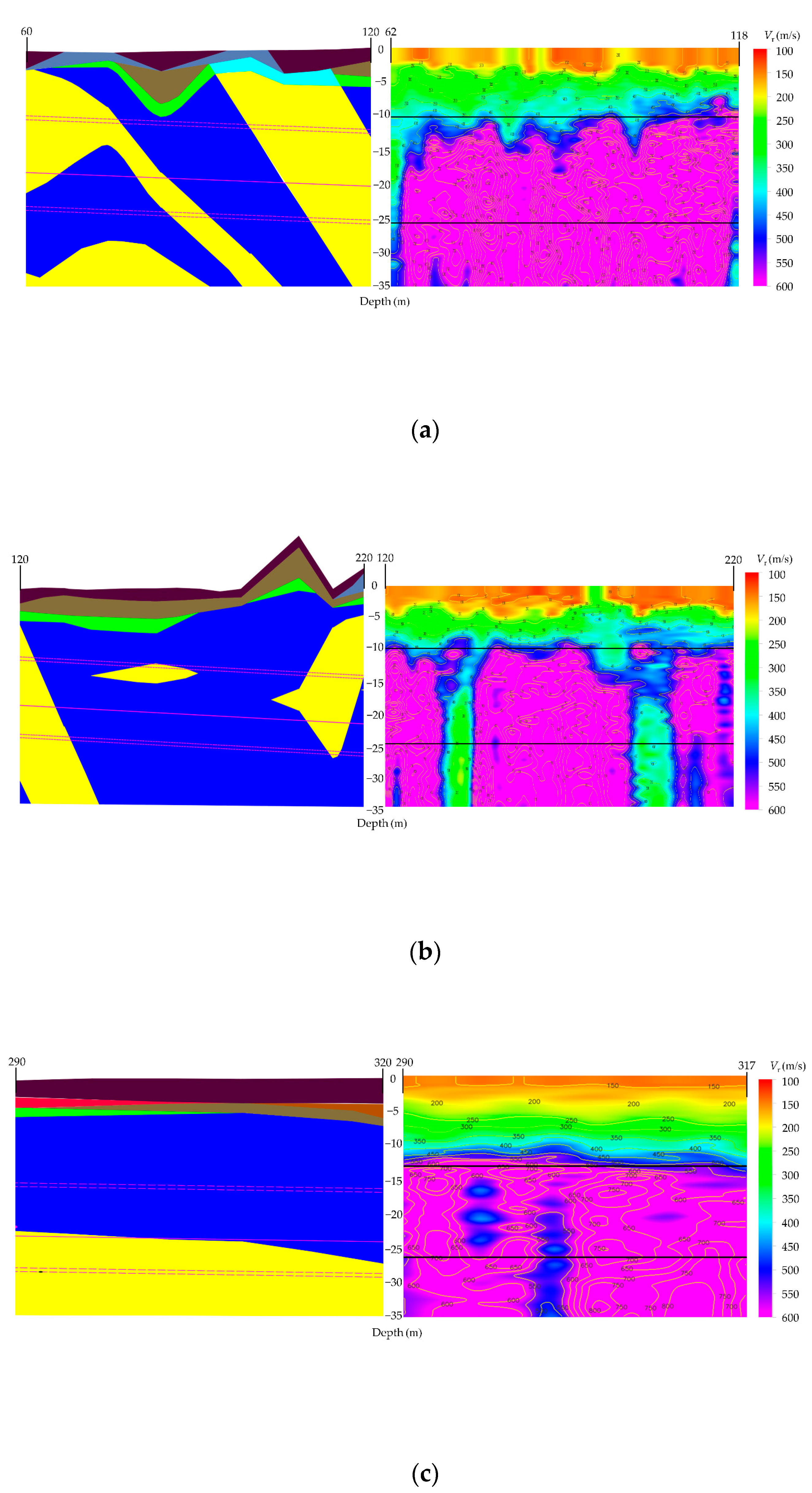
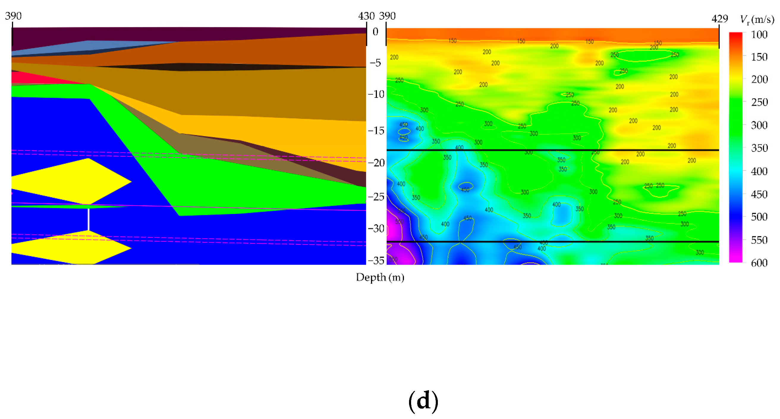
2.3. Arrangement of the Geological Microtremor Exploration and Field Monitoring Points

The microtremor exploration system is composed of a wireless digital geophone, a data acquisition station, etc. The wireless digital detector has a built-in detector, acquisition circuit, wireless synchronization circuit, digital processing circuit, and communication circuit for high-precision acquisition of micro-motion signals. A microtremor signal is a complex vibration composed of a body wave (P wave and S wave) and surface wave (Rayleigh wave and Love wave), in which surface wave energy accounts for more than 70% of the signal. Microtremor exploration mainly uses the dispersion information of the surface wave (Rayleigh wave) to calculate the velocity structure of the underground medium. The results obtained by the geological drilling exploration method are point-like distributions. Under complex engineering geological conditions, there may be local geological mutations between these points. The method of geological drilling exploration will produce a lot of blind spots. Combined with the geological advanced exploration technology–VIDO microtremor exploration system, it can comprehensively understand the geological conditions, improve the efficiency of shield construction, and ensure safety. This study explored the geological conditions of Rings 62 to 429 from 2 # to 3 #, working well along the tunneling direction. In this direction, the spatial coincidence exploration of four boreholes, ZK082, ZK085, ZK088, and ZK093, was carried out to verify the reliability of geological advanced exploration technology.
Microtremor exploration uses a circular array, and the radius distance is selected from 1 to 5 m according to the depth; moreover, the point circles of adjacent arrays are tangent. The alignment direction of microtremor exploration is approximately along the axis direction of the tunnel to detect the geological conditions within the depth range of the tunnel. The microtremor exploration depth can reach 20–30 times the array radius. As the tunnel depth is 20 m in this case, the array radius can be selected as 1–1.5 m. Moreover, a high-resolution frequency wavenumber domain (HRFK) algorithm is used to extract the Rayleigh wave dispersion curve from data. Calculating visual wave velocity or directly using phase velocity and then obtaining a two-dimensional visual wave velocity profile or phase velocity contour map through interpolation and smooth calculation can objectively and intuitively reflect the velocity structure of underground rock and soil layers. The array arrangement is shown in Figure 3.
The electronic level with an accuracy of 0.1 mm/km was used to obtain the surface settlement values in the field. In addition, steel tapes and leveling staff were also used as secondary measuring tools. Nine monitoring points are arranged between −10 m and 30 m along the vertical direction of the 101 Ring and 130 Ring of the tunnel axis. Each monitoring point is drilled with a drilling rig in advance to fix steel bars longer than 1.5 m in the undisturbed soil of the monitoring point. The external earth pressure of the tunnel segment is obtained by automatic monitoring based on the earth pressure gauge. The positioning ring is welded and fixed; the earth pressure gauge is installed and connected to the automatic acquisition instrument. Seven earth pressure gauges are arranged on the 110-ring segment. The layout of the monitoring points of the surface settlement and the layout of the pressure gauge outside the tunnel segment is shown in Figure 4.

3. Results and Discussion

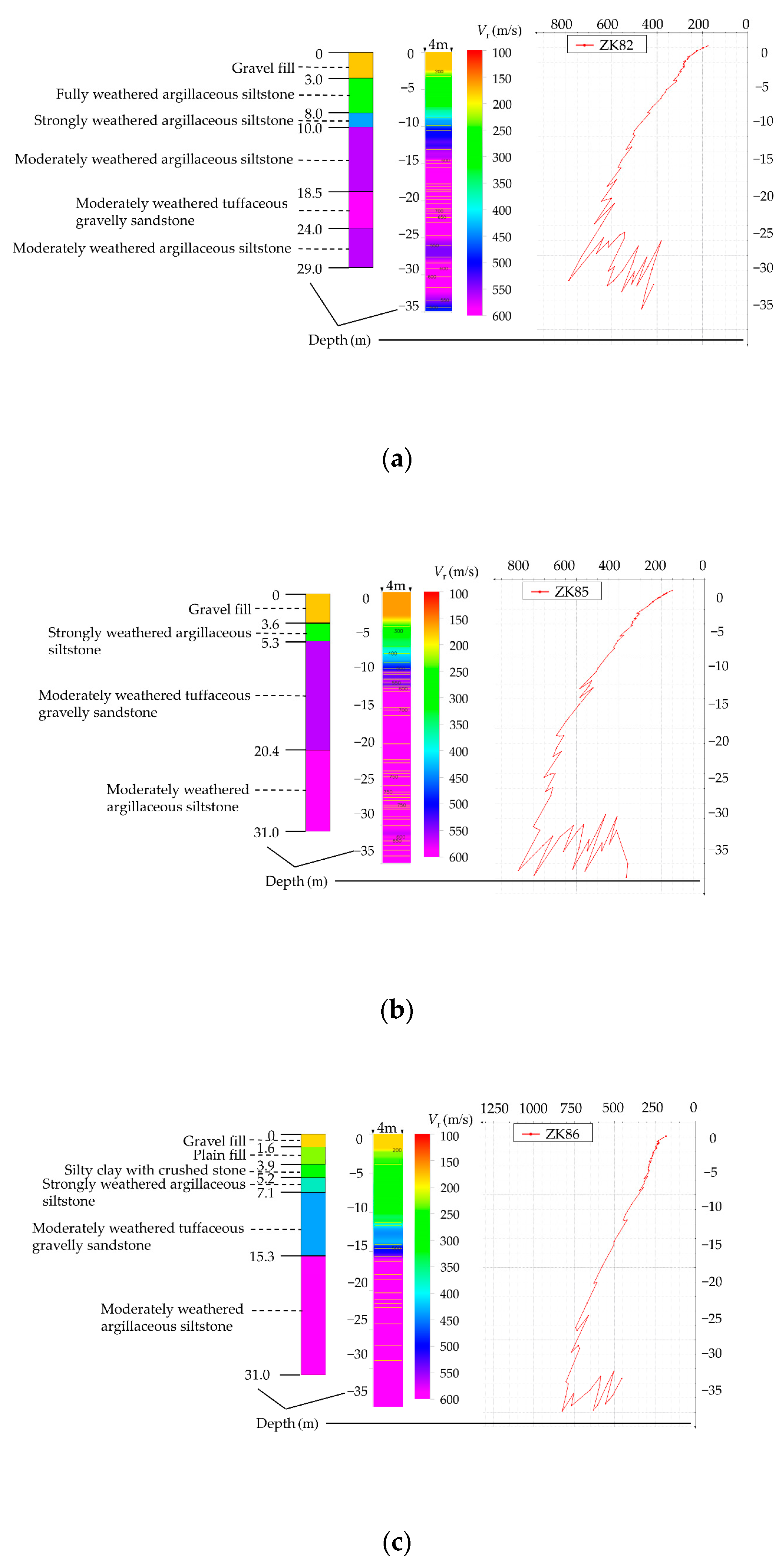
3.1. Measured Analysis of Advance Microtremor Exploration

Geological exploration is one of the most critical preparations in tunnel construction. The scope of shield tunneling excavation face includes mudstone, sandstone, gravelly soil, pebble, clay, and other complex geology, which may have a local geological mutation. The combination of advanced microtremor and borehole exploration can clarify the geological situation. Timely adjusted construction parameters according to geological conditions, such as mud water pressure, jack thrust, grouting pressure, etc., will make shield tunneling more efficient and reliable.
It is divided into four parts along the tunnel axis to analyze and compare the results of microtremor exploration. They are Rings 62–118, 121 to 217, 290 to 317, and 390–429, as shown in Figure 5. The result of the surface wave phase velocity from microtremor exploration is coincident with that from borehole exploration. The difference between the two is that the geological conditions between boreholes are estimated. At the same time, the results obtained by microtremor exploration are continuous and have an enormous scope, showing more details of the actual stratum. Among them, the radius of the microtremor exploration array from Ring 62 to Ring 118 is 2 m. When the shield machine reaches and drives out of the geological range, the wave velocity reflected by the geological conditions at the bottom of the tunnel is low, i.e., 300–400 m/s. This indicates that the soil in this part of the stratum is relatively loose, which will likely change the shield machine’s tunneling attitude. Therefore, construction parameters such as slurry balance and grouting pressure need to be adjusted in advance. The geology of Rings 64 to 116 reflects normal rock wave velocity without obvious abnormality. The radius of the array from Rings 121 to 217 is 3 m. The results show that there are inhomogeneous bodies with low wave velocity in Rings 142, 145, 181, 184, and 187, and that the wave velocity is 300–400 m/s. Construction parameters shall be adjusted timely when shield tunneling approaches this section. The radius of the array from Rings 290 to 317 is 3 m, and the geological wave velocity of the Ring 302 section is low, i.e., 400–500 m/s. The radius of the micro motion array of Rings 390–429 is 3 m. At Ring 390 along the tunnel direction, the interface of the soil rock composite stratum began to appear, the wave velocity of the stratum decreased to 300–400 m/s, and the subsequent stratum results were roughly the same as the distribution trend of the geological profile obtained by drilling.
In order to verify the reliability of microtremor geological exploration, an array with a radius of 2 m was set up at the position of holes ZK082, ZK085, ZK086, and ZK093 along the tunnel. The comparison between the geological results measured by borehole and the results obtained by microtremor exploration is shown in Figure 6. The figure also shows the change in geological wave velocity obtained by microtremor exploration. It can be seen from the comparison results in the figure that the stratum structure information obtained by microtremor exploration in this study is highly consistent with the analysis data of the drill core, which can further verify the reliability of this method.

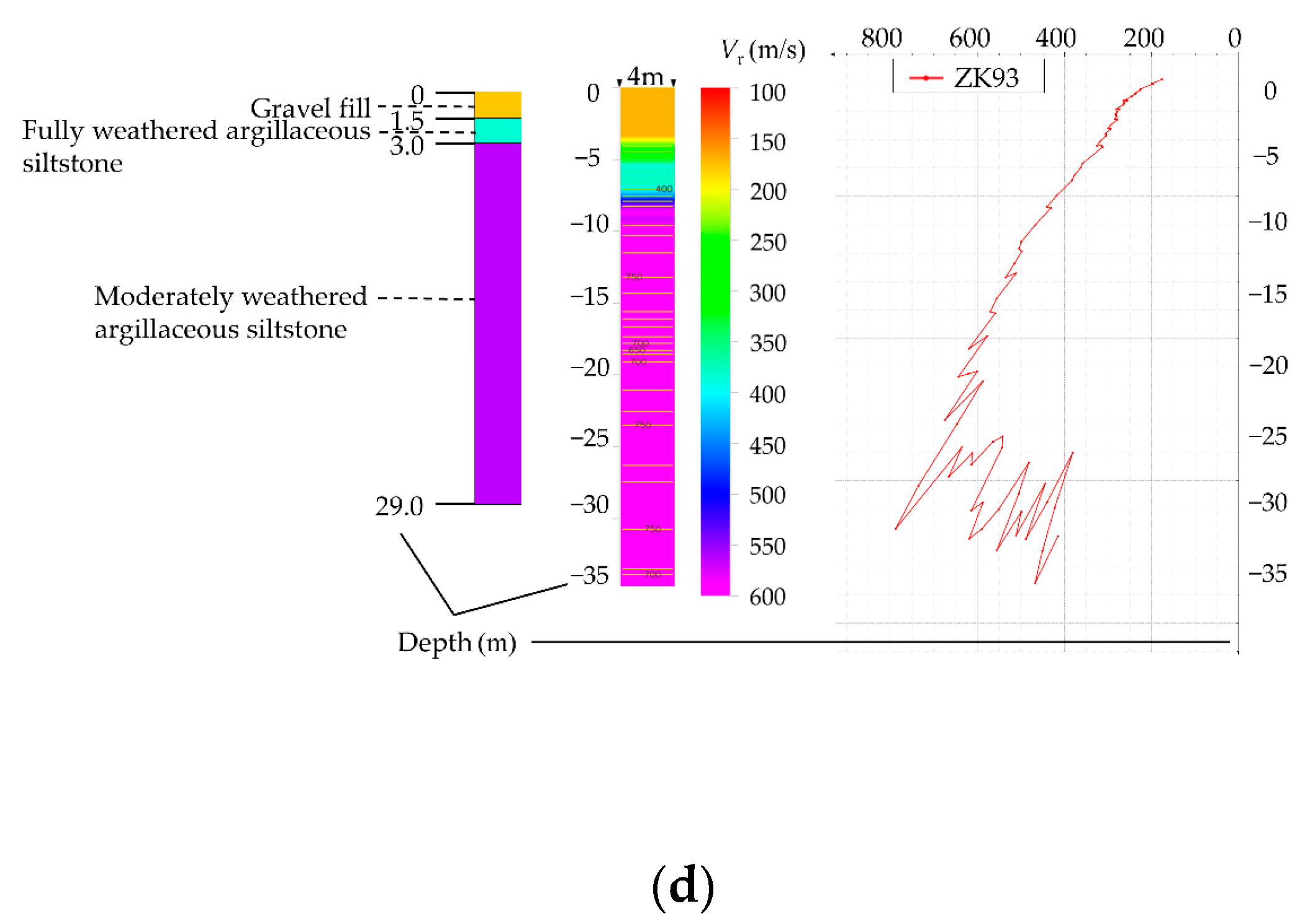
3.2. Shield Tunneling Parameters

A large number of engineering practices show that the shield tunneling parameters are one of the crucial factors affecting the surrounding ground deformation. According to the geological report produced by the joint application of drilling exploration and microtremor advanced exploration technology, the shield driving parameters were adjusted in time. In the process of shield tunneling, the main tunneling parameters of the shield machine, such as total thrust, cutterhead torque and rotation speed, tunneling speed, cut mud water pressure, grouting pressure, and grouting volume, are recorded in real-time. Figure 7 shows the main tunneling parameters of the monitoring section. The grouting hole at the upper right of the segment is selected for the record of grouting parameters. The chamber earth pressure is the average value of each chamber. The geological report results show that there is mainly moderately weathered argillaceous siltstone and moderately weathered tuffaceous gray sandstone within the monitoring range. These have high permeability and significant losses due to dissipation after grouting. Therefore, the grouting pressure is mainly about 0.35 MPa, and the grouting volume of the upper right grouting hole is about 6 m3. The torque can also reflect the difficulty of rock cutting. According to the geological survey results of microtremor exploration, there is relatively weak soil near Ring 118, therefore the torque, tunneling speed, and top pressure of the slurry chamber are also appropriately reduced. The variation trend of torque is consistent with that of total thrust, which is consistent with the conclusion of Xu [26]. At about Ring 122, the soil quality is enhanced, and the corresponding total thrust, grouting pressure, and other parameters are increased. When slurry balanced shield tunneling is adopted, it is difficult to adjust the front support pressure in blocks, while the grouting pressure and jack thrust can be flexibly adjusted at different locations of the shield tunnel section. This feature should be brought into full play, and the grouting pressure and jack thrust should be increased at the side of the shield tunnel’s abnormal pressure load to avoid the shield tunnel’s uneven settlement or axis deviation.

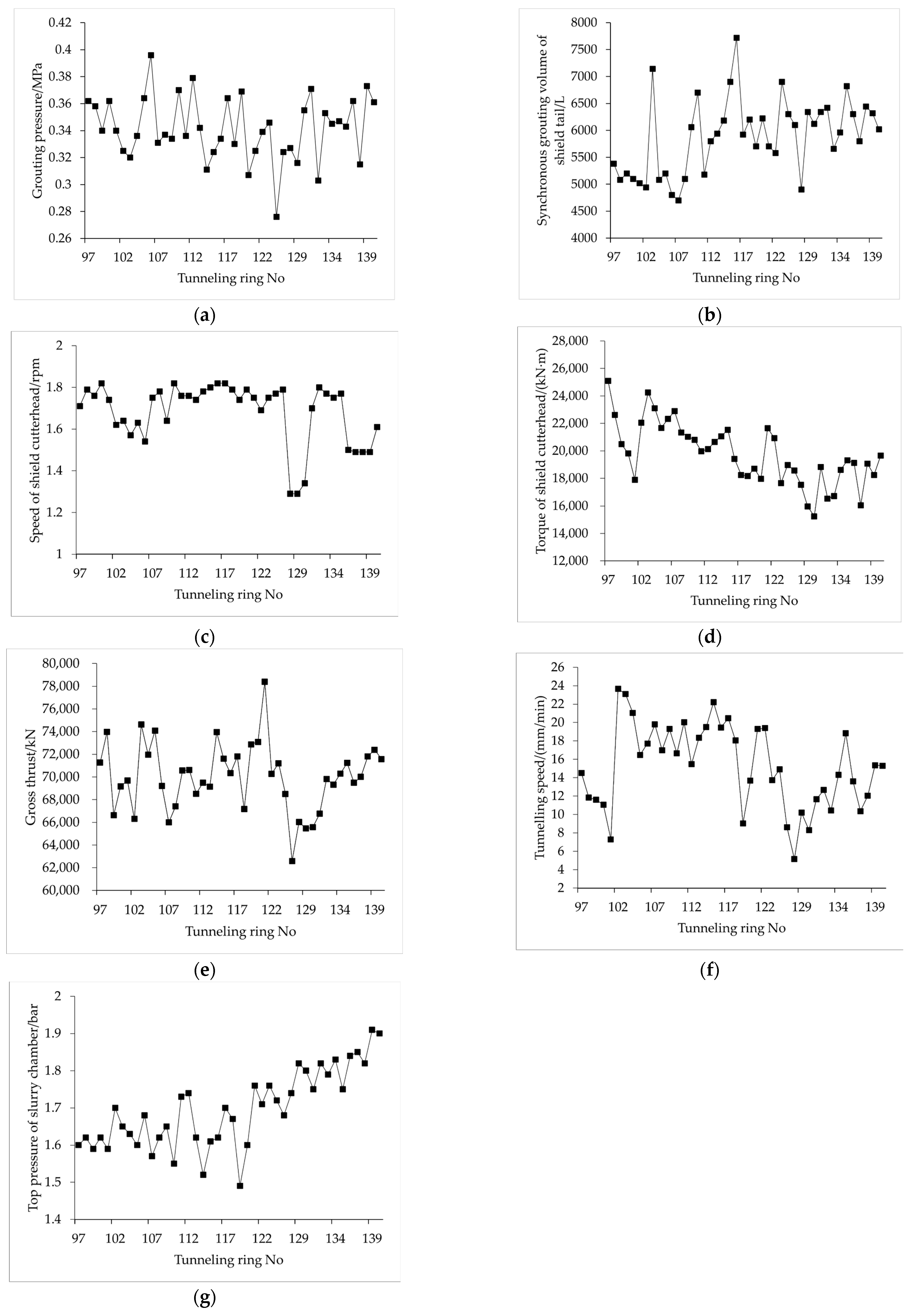
3.3. Surface Settlement Analysis

Surface settlement is one of the most important indicators used to judge the degree of impact on the surrounding environment. Excessive settlement might cause pavement collapse, endanger the surrounding facilities’ safety, and even cause serious engineering accidents.
The surface deformation curves of the sections of Rings 101 and 130 are shown in Figure 8, where the positive value represents the surface uplift, and the negative value represents the surface subsidence. The results show that the surface deformation of the two sections has experienced the trend of uplift first and then subsidence. This is because of the influence of tunnel face thrust, grouting pressure, shield tail gap, and other factors. During the shield cutter head passing through the measuring point section, due to the shield tail grouting, the Ring 101 section reached the maximum uplift value of 2.9 mm, which increased by 3.19 mm compared with the deformation before the measuring point. The Ring 130 section reaches the maximum uplift value of 1.29 mm, 1.36 mm higher than before reaching the measuring point. After the shield tail passes through, there is a gap between the soil and the segment, and the overlying soil moves downward. Both sections show large settlements. After the cutter head passes far away from the measuring point, the settlement increases further with the dissipation of excess pore water pressure and the consolidation and compression of the soil. The final uplift of the 101-ring section is 2.9 mm, and the final uplift of the 130-ring section is 0.3 mm. In addition, due to the partial load caused by an extensive range of slopes and high retaining walls on the left side of the excavation direction, the soil settlement near the tunnel axis is inconsistent, and the settlement on the left side is significantly larger than that on the right side. This may be because the formation stress on the eccentric loads side is larger.

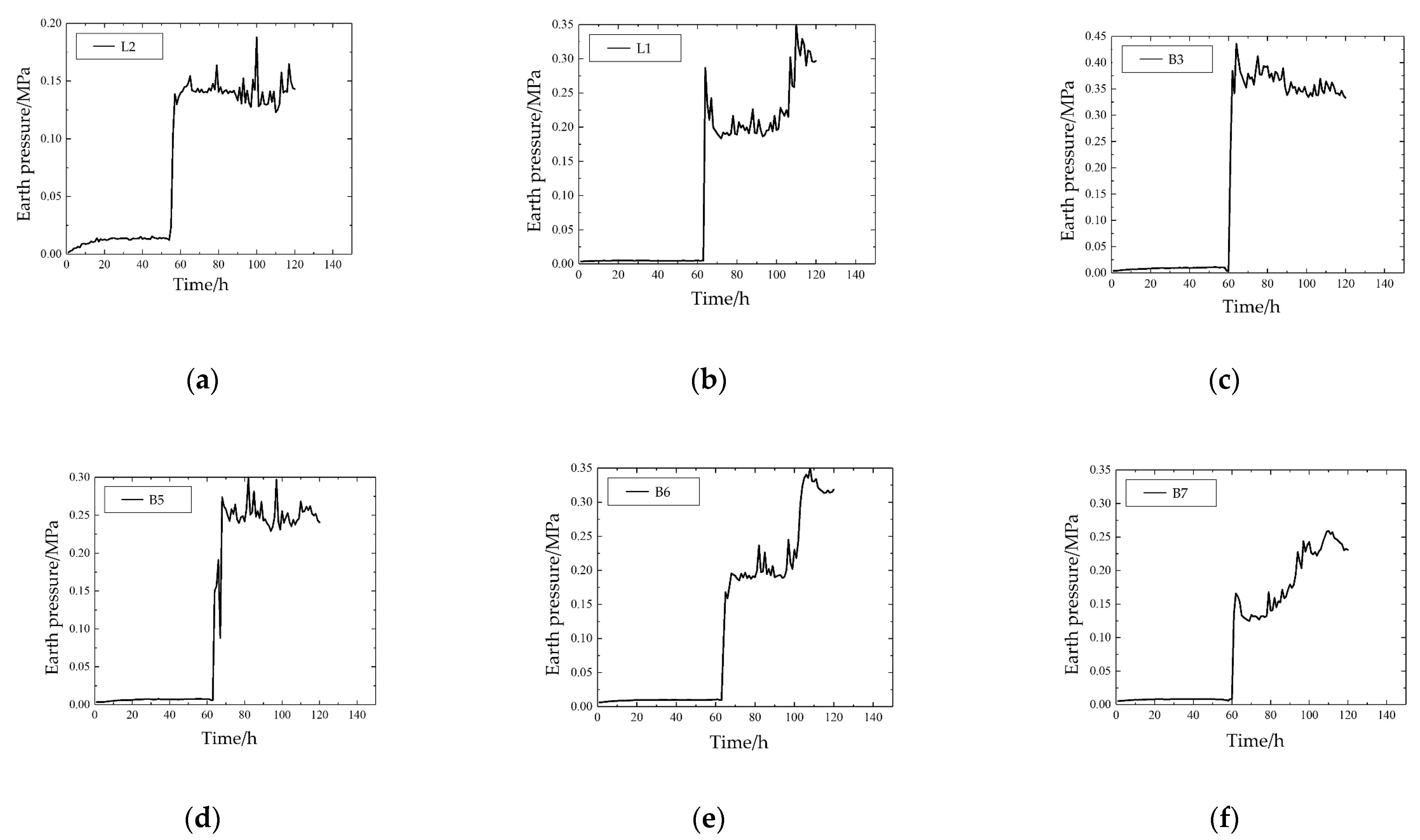
3.4. Earth Pressure Outside the Tunnel Segment Analysis

Figure 9 shows the monitoring data of earth pressure arranged outside the tunnel segment. The damage to the pressure gauge outside the B1 segment leads to abnormal data that cannot be analyzed. According to the results of soil pressure changes, it can be found that the soil water pressure on each segment increases gradually with the development of the grouting time. The maximum earth pressures on segments L2, L1, B3, B5, B6, and B7 are 0.1638, 0.3179, 0.4124, 0.2678, 0.3503, and 0.2592 MPa, respectively. The earth pressure gauge shows no noticeable pressure change in the shield tail brush of the shield machine. The pressure increases sharply when the shield machine advances until the earth pressure gauge enters the shield tail brush. This is because, before the grounded segment pressure gauge enters the shield tail brush, it is in contact with the air in the shield machine, while the shield tail brush is a sealed chamber with a certain pressure. When it enters the shield tail brush, it is immediately under the pressure of the sealed chamber.
The pressure change outside the segment tends to be stable after grouting for about 1 h. Moreover, it can be seen from the 105-h monitoring data that the upper segment pressure has increased significantly while the lower segment pressure has increased slightly. Section 3.1 shows apparent geological changes near Ring 110, and the grouting pressure and amount have been adjusted. At this time, the shield tail is about 7 m away from the monitoring section, indicating that the change of grouting parameters within the 7 m range will affect the segment pressure within this range. Since the grouting entrance is located on the upper side of the section, the segment in the upper range will receive more strokes and be affected more significantly. After the earth pressure monitoring section comes out of the shield tail brush, the segment pressure will increase with the grouting pressure, and the pressure will become stable after five days. In addition, the earth pressure on the upper side of the lining structure is smaller than that on the lower side. This is because, in the whole grouting process, with the continuous increase in grouting volume, the shield tail pores are gradually filled, and the grouting body, as a part of the tunnel structure, will directly bear and transmit the pressure from the soil mass.

4. Conclusions

In this study, the microtremor exploration method was conducted to carry out advanced geological detection that cannot be determined by borehole detection. The results were compared with those of borehole sampling. The shield construction parameters were guided and adjusted according to different geological conditions, the surface deformation perpendicular to the tunnel axis was monitored, and the earth pressure outside the segment was monitored with an automatic earth pressure monitoring system. The following conclusions can be drawn:
  • The geological results obtained from microtremor exploration can make up for the shortcomings of traditional borehole geological exploration. The geological distribution obtained by microtremor exploration is consistent with the results of four borehole samples, which can clarify the effectiveness and reliability of this detection method. This method can predict the possible local geological mutation in the ground in front of the tunnel and adjust the construction parameters in advance to ensure the safety of shield construction;
  • Through the dynamic adjustment of grouting parameters, the surface deformation is shown as overall settlement, and the curve law conforms to the settlement distribution of the Peck formula. The vertical displacement of soil mass mainly goes through five stages: small deformation far from the section, extrusion uplift close to the section, reciprocating uplift deformation through the section, settlement after the shield tail is pulled out, and consolidation settlement deformation law far away from the section. The surface subsidence on the eccentric load’s side is more obvious. The volume of ground settlement in the shield tail stripping stage has increased significantly, and the grouting behind the wall should be given more attention in actual projects;
  • When the earth pressure monitoring section is outside the shield tail brush of the shield machine, there is no apparent pressure change. When the shield machine is advanced, the earth pressure outside the segment increases dramatically when it enters the shield tail brush range. The maximum pressure outside the tunnel segment appears on the lower side of the monitoring section, at approximately 0.41 MPa. When it comes out of the shield tail brush, it increases with the increase of grouting pressure and tends to be stable in the following days.
The methods and results might be of interest to engineers, tunnel researchers, and industrial geologists who focus on advanced engineering geological exploration and shield tunnel construction. Microtremor exploration only detects the geological conditions in front of the tunnel, ignoring the identification and analysis of different underground obstacles, including pile foundations, diaphragm walls, existing tunnels, faults, karst, boulders, and other unfavorable geological bodies. Only the data comparison between the stratum and a small number of investigation holes is considered, and the fretting detection of a large number of investigation holes should be carried out subsequently to form a database and to comprehensively and deeply study the fretting detection method. In addition, the monitoring section is located on the main road. This study did not reach the rock cross stratum section for monitoring due to safety considerations. In the future, we will look for more suitable engineering cases for the in situ test of soil deformation and further explore the law of soil deformation caused by shield tunneling in the composite stratum.

Author Contributions

Conceptualization, methodology, supervision, Z.W., X.L. and Y.X.; data curation, formal analysis, J.S. and R.W.; investigation, original draft preparation, formal analysis, J.S., R.W. and Z.Y.; writing—review and editing, Z.W. and J.S.; project administration, X.L. and Y.X. All authors have read and agreed to the published version of the manuscript.

Funding

This research has been financed and jointly supported by the Joint Fund of Zhejiang Natural Science Foundation Committee Power China Huadong Engineering Corporation, grant number LHZ19E090001.

Institutional Review Board Statement

Not applicable.

Informed Consent Statement

Not applicable.

Data Availability Statement

Not applicable.

Acknowledgments

This work was financially and jointly supported by the Joint Fund of Zhejiang Natural Science Foundation Committee Power China Huadong Engineering Corporation. The support is gratefully acknowledged by the authors.

Conflicts of Interest

The authors declare no conflict of interest.

References

  1. Siegmund, B. Tunnelling machines in soft ground: A comparison of slurry and EPB shield systems. Tunn. Undergr. Space Technol. 1991, 6, 169–174. [Google Scholar] [CrossRef]
  2. Qian, W.F.; Lu, Y.; Huang, M.; Zhan, J.W. Study on the evaluation of adaptability of shield machine type selection in coastal complex stratum. IOP Conf. Ser. Earth Environ. Sci. 2021, 861, 072105. [Google Scholar] [CrossRef]
  3. Cheng, H.Z.; Chen, J.; Chen, G.L. Analysis of ground surface settlement induced by a large EPB shield tunnelling: A case study in Beijing, China. Environ. Earth. Sci. 2019, 78, 605. [Google Scholar] [CrossRef]
  4. Li, X.Y.; Zhang, D.L.; Hou, Y.J. Analysis of Shield Tunnel Ground Deformation Characteristics and Affecting Factors in Water-Rich Soft Stratum: A Case Study on the Section Tunnel of Tianjin Metro Line 6. App. Sci. 2022, 12, 6208. [Google Scholar] [CrossRef]
  5. Liu, B.; Zhang, F.; Li, S.; Li, Y.; Xu, S.; Nie, L.; Zhang, Q. Forward modelling and imaging of ground-penetrating radar in tunnel ahead geological prospecting. Geophys. Prospect. 2018, 66, 784–797. [Google Scholar] [CrossRef]
  6. Li, S.C.; Liu, B.; Sun, H.F.; Nie, L.C.; Zhong, S.H.; Su, M.X. State of art and trends of advanced geological prediction in tunnel construction. J. Rock Mech. Eng. 2014, 33, 1090–1113. [Google Scholar] [CrossRef]
  7. Xu, P.F.; Ling, S.Q.; Li, C.J.; Du, J.G.; Zhang, D.M.; Xu, X.Q.; Dai, K.M.; Zhang, Z.H. Mapping deeply-buried geothermal faults using microtremor array analysis. Geophys. J. Internat. 2012, 188, 115–122. [Google Scholar] [CrossRef]
  8. Molnar, S.; Cassidy, J.F.; Castellaro, S.; Cornou, C.; Crow, H.; Hunter, J.A.; Yong, A. Application of microtremor horizontal-to-vertical spectral ratio (MHVSR) analysis for site characterization: State of the art. Surv. Geophys. 2018, 39, 613–631. [Google Scholar] [CrossRef]
  9. Benjumea, B.; Macau, A.; Gabas, A.; Bellmuntm, F.; Figueras, S.; Cires, J. Integrated geophysical profiles and H/V microtremor measurements for subsoil characterization. Near. Surf. Geophys. 2018, 9, 413–425. [Google Scholar] [CrossRef]
  10. Kolesnikov, Y.I.; Fedin, K.V. Detecting underground cavities using microtremor data: Physical modelling and field experiment. Geophys. Prospect. 2018, 66, 342–353. [Google Scholar] [CrossRef]
  11. Karakus, M.; Fowell, R.J. Effects of different tunnel face advance excavation on the settlement by FEM. Tunn. Undergr. Space Technol. 2003, 18, 513–523. [Google Scholar] [CrossRef]
  12. Shi, J.K.; Wang, F.; Zhang, D.M.; Huang, H.W. Refined 3D modelling of spatial-temporal distribution of excess pore water pressure induced by large diameter slurry shield tunneling. Comput. Geotech. 2021, 137, 104312. [Google Scholar] [CrossRef]
  13. Alshboul, O.; Shehadeh, A.; Tatari, O.; Almasabha, G.; Saleh, E. Multiobjective and multivariable optimization for earthmoving equipment. J. Facil. Manag. 2022. ahead-of-print. [Google Scholar] [CrossRef]
  14. Alshboul, O.; Shehadeh, A.; Hamedat, O. Development of integrated asset management model for highway facilities based on risk evaluation. Intern. J. Constr. Manag. 2021, 1–10. [Google Scholar] [CrossRef]
  15. Zou, H.; Chen, J. Analysis of Influence of Shield Tunneling in Soft Soil on Upper Railway Subgrade: A Case Study of Site Monitoring of a Section on Hangzhou Metro Line No. 2. Tunn. Constr. 2018, 38, 199–206. [Google Scholar] [CrossRef]
  16. Standing, J.R.; Selemetas, D. Greenfield ground response to EPBM tunnelling in London Clay. Géotechnique 2013, 63, 989–1007. [Google Scholar] [CrossRef]
  17. Clayton, C.R.I.; Berg, V.D.; Thomas, J.P. Monitoring and displacements at heathrow express terminal 4 station tunnels. Géotechnique 2006, 56, 323–334. [Google Scholar] [CrossRef]
  18. Wan, M.S.P.; Standing, J.R.; Potts, D.M.; Burland, J.B. Measured short-term subsurface ground displacements from EPBM tunnelling in London Clay. Géotechnique 2017, 67, 748–779. [Google Scholar] [CrossRef]
  19. Addenbrooke, T.I.; Potts, D.M. Twin tunnel interaction: Surface and subsurface effects. Intern. J. Geo. 2001, 1, 249–271. [Google Scholar] [CrossRef]
  20. Fang, Q.A.; Tai, Q.M.; Zhang, D.L.; Louis, N.Y.W. Ground surface settlements due to construction of closely-spaced twin tunnels with different geometric arrangements. Tunn. Undergr. Space Technol. 2016, 51, 144–151. [Google Scholar] [CrossRef]
  21. Xie, X.; Yang, Y.; Ji, M. Analysis of ground surface settlement induced by the construction of a large-diameter shield-driven tunnel in Shanghai, China. Tunn. Undergr. Space Technol. 2016, 51, 120–132. [Google Scholar] [CrossRef]
  22. Gan, X.L.; Yu, J.L.; Gong, X.N.; Zhu, M. Characteristics and countermeasures of tunnel heave due to large-diameter shield tunneling underneath. J. Perform. Constr. Fac. 2020, 34, 04019081. [Google Scholar] [CrossRef]
  23. Zhao, T.C.; Ding, W.Q.; Qiao, Y.F.; Duan, C. A large-scale synchronous grouting test for a quasi-rectangular shield tunnel: Observation, analysis and interpretation. Tunn. Undergr. Space Technol. 2019, 91, 103018. [Google Scholar] [CrossRef]
  24. Yang, H.X.; Cao, J.; Liang, B.; Ding, Z.D.; Zhao, H.M. Study on synchronized grouting pressure to segments of shallow EPB shield tunnel. Adv. Mater. Res. 2013, 859, 298–303. [Google Scholar] [CrossRef]
  25. Gan, X.L.; Yu, J.L.; Gong, X.N.; Hou, Y.M.; Liu, N.W.; Zhu, M. Response of operating metro tunnels to compensation grouting of an underlying large-diameter shield tunnel: A case study in Hangzhou. Undergr. Space 2022, 7, 219–232. [Google Scholar] [CrossRef]
  26. Xu, Q.W.; Zhu, H.H.; Ding, W.Q.; Ge, X.R. Laboratory model tests and field investigations of EPB shield machine tunnelling in soft ground in Shanghai. Tunn. Undergr. Space Technol. 2011, 26, 1–14. [Google Scholar] [CrossRef]
Figure 1. Project Overview.
Applsci 13 00263 g001
Figure 2. Longitudinal geological profile of the interval tunnel.
Applsci 13 00263 g002
Figure 3. Array arrangement.
Applsci 13 00263 g003
Figure 4. The layout of monitoring points for surface settlement and pressure gauges outside tunnel segments.
Applsci 13 00263 g004
Figure 5. Comparison between microtremor exploration results and geological profile: (a) Rings 62 to 118; (b) Rings 121 to 217; (c) Rings 290 to 317; (d) Rings 390 to 429.
Applsci 13 00263 g005aApplsci 13 00263 g005b
Figure 6. Comparison between microtremor exploration results and drilling geological results: (a) ZK082; (b) ZK085; (c) ZK086; (d) ZK093.
Applsci 13 00263 g006aApplsci 13 00263 g006b
Figure 7. Main tunneling parameters of the monitoring section: (a) grouting pressure; (b) synchronous grouting volume; (c) speed of shield cutterhead; (d) torque of shield cutterhead; (e) gross thrust; (f) tunneling speed; (g) top pressure of slurry chamber.
Applsci 13 00263 g007
Figure 8. Surface deformation: (a) section of DBC-L-101; (b) section of DBC-L-130.
Applsci 13 00263 g008
Figure 9. Variation of earth pressure outside the segment with time: (a) L2; (b) L1; (c) B3; (d) B5; (e) B6; (f) B7.
Applsci 13 00263 g009
Table 1. Soil parameters.
Geotechnical CategoryNatural Unit Weight/
kN/m3
Cohesion/
(kN/m2)
Coefficient of Earth Pressure at RestHorizontal Permeability Coefficient/
(cm/s)
Vertical Permeability Coefficient/
(cm/s)
Friction angle/(°)Compression Modulus/
MPa
Rock Compressive Strength/
MPa
①-1 gravel fill19.32.00.486.00 × 10−25.50 × 10−215.04.0-
①-2 plain fill18.54.00.506.00 × 10−55.00 × 10−524.03.0-
(20)-a2 strongly weathered argillaceous siltstone20.324.00.353.00 × 10−42.50 × 10−426.018.0-
(20)-a3 moderately weathered argillaceous siltstone25.0230.00.325.00 × 10−64.50 × 10−635.0Incompressibility5.6
(20)-c2 strongly weathered tuffaceous gravelly sandstone20.524.00.354.00 × 10−43.50 × 10−426.019.0-
(20)-c3 moderately weathered tuffaceous gravelly sandstone 25.5300.00.298.00 × 10−67.50 × 10−638.0Incompressibility7.9
Disclaimer/Publisher’s Note: The statements, opinions and data contained in all publications are solely those of the individual author(s) and contributor(s) and not of MDPI and/or the editor(s). MDPI and/or the editor(s) disclaim responsibility for any injury to people or property resulting from any ideas, methods, instructions or products referred to in the content.

