Project Report

Reliability Enhancement Driven by ANN for Lighting Control System in Highway Tunnels

1
Faculty of Architecture, Civil and Transportation Engineering, Beijing University of Technology, Beijing 100124, China
2
Fujian Expressway Science & Technology Innovation Research Institute Co., Ltd., Fuzhou 350001, China
*
Author to whom correspondence should be addressed.
Appl. Sci. 2023, 13(1), 42; https://doi.org/10.3390/app13010042
Submission received: 24 October 2022 / Revised: 5 December 2022 / Accepted: 15 December 2022 / Published: 21 December 2022
(This article belongs to the Section Transportation and Future Mobility)

Abstract

:
Compared with open roadways, traffic safety in highway tunnels requires more attention to build smoothly transitioned and well-coupled light environments for drivers to alleviate visual discomfort so as to achieve a balanced sense of driving safety and comfort. In this study, in order to overcome the drawbacks of existing tunnel lighting control modes that disregard the color temperature of natural light characteristics and collaborative influence of color temperature and luminance of natural light on tunnel lighting quality, one artificial neural network (ANN) model is designed and trained to simulate one physical lighting control system that takes into consideration color temperature and luminance simultaneously. In this model, multiple parameters of discrete and continuous types of input layer and output layer are synergistically analyzed. The model was also trained with quantities of field data from one tunnel in service and includes one hidden layer with 10 neurons. The simulation results showed that this model obtains a high degree of fitness with inside luminance and 100% recognition rate with inside color temperature in the threshold zone, which conforms to the regulation strategy of actual lighting control systems with high confidence. The proposed model will greatly enhance the reliability and sustainability of the lighting system during its normal operation, which can also support other lighting scenarios due to its flexibility and scalability with multiple-input and multiple-output (MIMO) capabilities.

1. Introduction

As one of the most complex and expensive infrastructure facilities, tunnels provide many advantages through fast and reliable transport, saving time, and sometimes connecting places that could not be reached in any other way, making them necessary and desirable infrastructure facilities despite the high financial investments required.
Recently, the construction scale of global highway tunnels has been increasing year by year. Up to the end of 2021, China had 23,268 highway tunnels (shown in Table 1) stretching 24,698,900 m in total [1], ranking first worldwide in terms of scale and number of tunnels. While improving traffic efficiency, tunnel areas have also become bottleneck sections for the normal operation of the whole highway network to a large extent, and the safety situation in tunnel areas is becoming increasingly serious.
According to the annual statistics of the Traffic Management Bureau of the Ministry of Public Security of China, the number of tunnel traffic accidents accounts for 0.23% of the total number of highway traffic accidents, but the share of casualties and direct property losses reach 0.32% and 0.95%, respectively [2]. This indicates that accidents in tunnel areas are more hazardous than those in other sections. Furthermore, due to the relatively closed space, abnormal tunnel traffic accidents often happen quickly with unclear causes, evacuation difficulty and emergency rescue are worse than in open roadways, and improper protective measures are likely to cause secondary accidents which set off a chain reaction in terms of economic losses and social impact.
Studies show that under normal driving conditions, drivers rely on visual cognition to capture more than 80% of road traffic information during driving [3]. The visual condition is closely related to traffic safety, and the light environment conditions of the highway tunnel directly affect drivers’ visual characteristics. The tunnel interior space is relatively narrow and well-sealed, and the low brightness level and slow spread of vehicle exhaust fumes limit drivers’ visual recognition ability, which heavily impacts on the safety of tunnel driving. When drivers enter the transition area between the natural and artificial light environments, the great difference in light leads to a “white hole” or “black hole” effect on drivers’ vision, thus a “blind” vision period is initiated. In turn, the resulting visual discomfort plays a part in some traffic accidents.
Human eyes are good at adapting to changing levels of brightness but need some time to adjust, this duration depends on how long light adaption or dark adaption takes for a specific driver. Sudden variations in the amount of light when entering or exiting a tunnel must be avoided as much as possible. In the middle of the tunnel, lighting levels can be lower, but again, avoiding sudden variations is important. Towards the evening, or if the conditions are otherwise darker (for example, in heavy rain), lighting should adapt so that it is dimmer.
Psychologically, driving inside a hollow, grey, and unnatural atmosphere may also cause feelings of anxiety. Light uniformity with no yellowish areas or dark corners can bring comfort to an uncomfortable ambient area, and in the case of an emergency, good lighting can also reduce panic and help guide people out. Statistics of accidents in Chinese tunnels carried out by Pervez et al. [4] indicate that rear-end collisions caused by failure to maintain a safe distance constituted almost 60% of accidents, and drivers are less effective in perceiving speed and distance when driving in road tunnels.
Furthermore, these two factors of psychological and visual impairment are not independent but closely related, creating a negative synergy that possibly increases the risk for drivers in tunnels. This synergy clearly appears in some of the most common disturbing effects (distraction driving, frequent speed change, improper distance maintenance, etc.) in tunnels.
The task of tunnel lighting is to constantly provide the same level of safety and comfort for road traffic in the tunnels as on open roads. However, it is both uneconomical and technically difficult to keep the tunnel lighting environment close to the natural light outside the tunnel. Subject to the fact that the natural light conditions cannot be changed, it is necessary to construct good artificial lighting by technical means to realize the harmony and unity of natural lighting conditions with artificial lighting conditions, so as to achieve the smooth transition in to and out of tunnel light environments to ensure that road conditions ahead are visible to drivers, and that driving safety and comfort are maintained. In the meantime, tunnel lighting systems should supply drivers with complete visual comfort and avoid hidden dangers caused by inadequate visual information at every stage of the journey. Here, these stages are classified into different lighting zones according to drivers’ visual needs, which consist of access, threshold, transition, interior and exit zones [5].

2. Research Status of Tunnel Lighting System

Based on the above reasons, tunnel lighting has been extensively considered and studied worldwide. The hazards of traffic accidents and the lessons of secondary disasters related to tunnel lighting have repeatedly drawn the attention of experts in the field of transportation to the quality of tunnel lighting. The research into tunnel lighting systems mainly includes three aspects, the evolution of tunnel lights, the control modes of lighting sources and the overall architecture of lighting control system.

2.1. Evolution of Tunnel Lights

The efficiency of the tunnel depends on achieving a reliable lighting source. Since the first artificial tunnel in the world, namely the “Faint incline Road” in Qin Dynasty [6], tunnel lighting has included diverse and relatively simple lighting sources such as torches, kerosene and gas lamps, and so on.
Traditional tunnel lighting has consistently made use of incandescent lamps, fluorescent lamps, and high-pressure sodium lamps (HPSL) as light sources, however, with the rapid development of modern vehicle, transportation, logistics and other industries, there is excessive demand for superior optical properties of light sources (appropriate color temperature and excellent color rendering, lighting efficiency, luminous flux, light attenuation, service life, and visibility in the smoke of vehicle emissions). At the same time, with the progress in modern optical technology and manufacturing processes, LED lamps have comparatively more obvious comprehensive advantages in terms of technical parameters such as service life, color rendering, color temperature range, light flux utilization, and regulation convenience, as shown in Table 2.
At present, incandescent and fluorescent lamps are essentially no longer used in tunnel lighting, HPSL is being replaced by LED light sources on a large scale. The advantages of LED lights in the aspects of visual performance, luminous efficiency and production cost make them the ideal light source for the highway tunnel lighting environment [10].
Along with the evolution of lighting sources, the control mode of tunnel light sources is also evolving. This can be roughly categorized into artificial control, timing control and intelligent control. Intelligent control is the mainstream control mode of tunnel lighting sources at present. Moreover, the characteristics of 0–100% step-less dimming of LED light source has made step-less dimming the mainstream control method that is replacing the traditional logic switch method.

2.2. Key Requirements of Tunnel Lighting System

In tunnel environments, since access to maintenance of lighting components is limited and highly inconvenient, the reliable operation of lighting systems is of great importance. In general, an excellent lighting system should meet but not be limited to the following requirements:
(1). It should be suitable for the geographical and climatic conditions of specific areas of the tunnel, and meet the relevant national tunnel lighting specifications, such as the “Guide for the Lighting of Road Tunnels and Underpasses” [11] and the JTG/T D70/2-01-2014 “Guidelines for Design of Lighting of Highway Tunnels” [12].
(2). It should be equipped with the tunnel lighting lamps with high-quality design and production technology, excellent lighting output parameters and ease of maintenance.
A circumstance that complicates the process of tunnel lighting is the presence of high humidity and waste gases in the air, the combination of which can lead to the formation of sulfuric or nitric acid. In environments such as this, luminaires are at high risk of damage. Regular maintenance can alleviate the problems, but closing the tunnel due to such works is impractical for logistical reasons and high costs. In such demanding environments, the design and quality of luminaires are vital, helping to protect them from penetration of fine particles and acids, resistance to vibration, and reduced likelihood of physical damage or overheating. Therefore, tunnel lighting demands are harsh on lamps, including design level, production process, and maintainability, etc., all of which must be outstanding to succeed within the parameters.
(3). It should provide reasonable light environment indexes that help to improve the driving safety and comfort requirements in the tunnel area [13], which are also covered in the specifications in (1), for instance:
  • Color temperature and color rendering index.
  • Luminance reduction factor.
  • Road surface luminance.
  • Uniformity of road surface luminance.
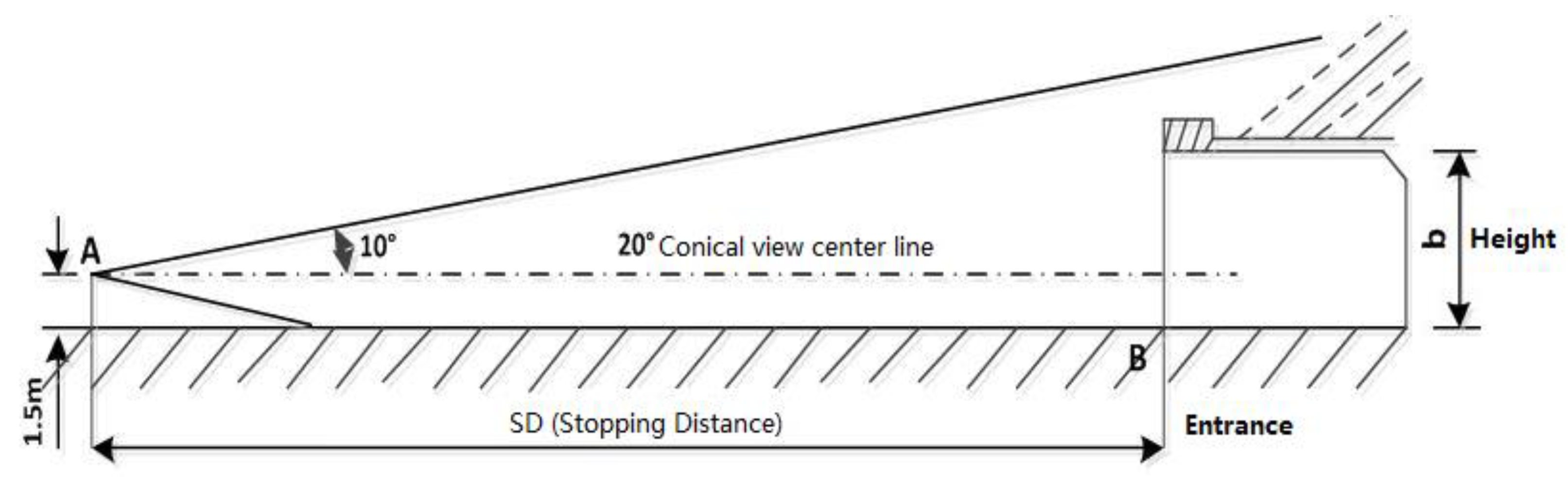
  • Visual cognition distance.
(4). It should possess some robustness and reliability features. Although there is no unified definition of standard of lighting system reliability, it can be evaluated according to the following aspects:
  • Greatly enhanced cyber security to ensure reliable operation and data transfer.
  • Meet the highest tunnel safety standards to improve driver safety.
  • Helpful to reduce traffic accidents and tunnel closures.
  • Dynamic and real-time response to light conditions to help drivers’ eyes acclimatize as they enter and exit the tunnel.
  • Correct lighting levels at every stage.
  • Manage lighting easily with intelligent control and online diagnostics.
  • Less downtime and minimized disruption of traffic flow.
  • Nearly always ready for unexpected events.
  • Simple process to refurbish tunnel lights and upgrade components of the lighting system.
  • Easy to manage and operate components of the lighting system remotely.
  • Lower MTBF with both tunnel lights and control system.
(5). It should align with the sustainability required by worldwide societal progress:
  • Reduced carbon footprint.
  • Decrease in maintenance costs.
  • Enhanced driving experience and safety guarantee without significant cost increase.
  • Balance of the main requirements of tunnel lighting, ensuring visual comfort and uniformity of light distribution, energy efficiency and ease of maintenance.

2.3. Progress of Tunnel Lighting Strategies

2.3.1. Characteristics of Visual Adaption in Highway Tunnels

Light and Dark Adaption

The tunnel entrance and exit are transition sections in the vehicle operating environment. Driving from the outside light environment to the inside artificial light environment through the tunnel entrance, or in the opposite direction driving out of the tunnel exit, the light environment differences between inside and outside exist objectively. If this difference is stark, it is likely to result in visual lag for drivers and cause short-term visual impairment. This is often called the black hole or white hole effect [14]. The reason for this visual impairment is a result of the inherent characteristics of human eyes, which cannot instantly adapt to a sharp increase or decrease in luminance level.
This visual adaptation is divided into light adaptation and dark adaptation. Light adaptation is from the dark to the light, eyes adapt to the increase in luminance level and are able to recover vision. Dark adaption refers to the changes in luminance level in the opposite direction and the visual system adapts to the low luminance level. Research has shown that dark adaptation takes place much more slowly than light adaptation [15,16], the whole process of light adaptation is short and it usually takes only tens of seconds in an artificial light environment, this indicates that the visual discomfort for drivers caused in tunnel entrance is more severe than that in tunnel exit, i.e., the black hole effect is more dangerous than the white hole effect.
If drivers fail to react appropriately to light adaption or dark adaption, the adverse effect will disturb drivers’ recognition of vehicles or obstacles ahead, as well as driving stability, driving safety and comfort, meaning that increased stress is imposed on drivers, eventually resulting in operational errors and traffic accidents.

Driver Adaption in Daytime and Nighttime

As defined by CIE in 1983, photopic vision refers to the vision when the luminance level is more than a few cd/m2 (normally 3 cd/m2). At this time, vision is mainly operated by cones and maximum visual response is at 550 nm in the blue-green range of the spectrum. Scotopic vision refers to the vision when the ambient luminance level is lower than 0.01 cd/m2. Rod cells are the main photoreceptors for scotopic vision and the peak of spectral optical efficiency is at about 490 nm. The luminance level of mesopic vision falls in between scotopic vision and photopic vision, cones and rods respond simultaneously to changes in luminance level.
In daytime or when the luminance level is greater than 3 cd/m2, this is considered photopic vision with better light conditions, and obstacles ahead are easy to identify and visual recognition time is shorter than that at nighttime. At nighttime or when the luminance level is lower than 0.01 cd/m2, little perceptible difference between obstacles and the background causes an increase in visual recognition time. Due to different luminance levels and the regulatory role of eyes, visual information captured by drivers differs greatly between daytime and nighttime.
In low-illumination tunnel environments, frequent changes in light and dark phenomena often exist. Even if tunnel lighting is used, since lighting illumination is basically similar to environment illumination, visual recognition conditions of obstacles in the field of view are not significantly improved, which can easily lead to ambiguous visual recognition and erroneous distance judgment. In the process of visual adaptation, drivers are often unable to perceive obstacles ahead clearly and instantly, and insufficient visual information regarding obstacles will degrade the quality of visual recognition and endanger driving safety.

Restriction of Glare and Flicker Effect

When the luminance level of a light source or reflection surface in the field of view is too high, or the brightness contrast between a light source and its background is extremely high, this will cause visual discomfort for the driver and reduced visibility of the visual target, this is called glare. American physicist Holladay put forward the concept of glare in 1926 and thought that the effect of glare on visual function was mainly caused by equivalent veiling luminance in people’s eyes.
Glare is one important factor affecting lighting quality and the comfort of the light environment. When glare exists, a driver’s pupils shrink significantly and a light spot is formed in eyes, causing visual discomfort or vision loss, and greatly impairing the visual system’s adaptation to the surrounding physical space, thus, it is difficult for drivers to visually recognize obstacles or sudden information ahead, which is likely to trigger traffic accidents.
There are many possible causes of glare, as listed below:
(1)
Unreasonable design of the tunnel lighting, for example, improper location and angle of the lighting fixtures.
(2)
Reflected light from a mirror or reflective material on the side wall.
(3)
Strong intensity of the active luminous sign profile, especially in the tunnel curve section.
(4)
Direct sunlight from the tunnel exit.
(5)
Dense vehicle exhaust fumes illuminated by high-power lights.
(6)
Sudden increase in the luminance level when approaching the tunnel exit.
Sammarco J. et al. conducted a comparative evaluation test with LED and other lighting sources on the impact of target response time, recognition accuracy and impact of visual effects from subjective discomfort caused by glare, and proved that LED lighting was conducive to improving the visual recognition effect under mesopic vision [17]. Additionally, many measures have been tried to restrict this undesirable glare effect, including:
(1)
Reasonable tunnel orientation to avoid direct sunlight from the tunnel exit.
(2)
Similar color temperature in interior zone and outside tunnel.
(3)
All enhanced lighting fixtures switched off at nighttime.
(4)
Use of tunnel portals with lower reflectivity.
(5)
Dark material used for pavement inside tunnel.
(6)
Dark material paving at least one stopping distance in the access zone and parting zone.
(7)
Vegetation or shrubs planted around the tunnel portals.
(8)
Buildup of anti-glare structures, such as shading shed or shading panel, etc.
In addition to glare, the flicker effect should also be restricted, as suggested by CIE. The flicker effect of tunnel lighting is similar to that of light sources. While driving in the tunnel, if the spacing of light fixtures leads to a zebra crossing pattern with alternating light and dark, and if the alteration frequency of light and dark falls within 2.5–15 Hz, this flicker effect will cause visual discomfort and psychological interference to drivers. How severe flicker effect caused visual discomfort depends on the following factors:
(1)
Number of luminance changes per second (flicker frequency).
(2)
Duration of this flicker effect.
(3)
Ratio of peak luminance to trough luminance.
All these factors rely on vehicle speed and light fixture spacing. Flicker effects lower than 2.5 Hz and above 15 Hz are negligible. When this frequency is within 4–11 Hz and the duration exceeds 20 s, if no measures are taken, drivers will feel uncomfortable. In this case, it is recommended to avoid the frequency range of 4–11 Hz [11].

2.3.2. Existing Lighting Strategies on Luminance Level

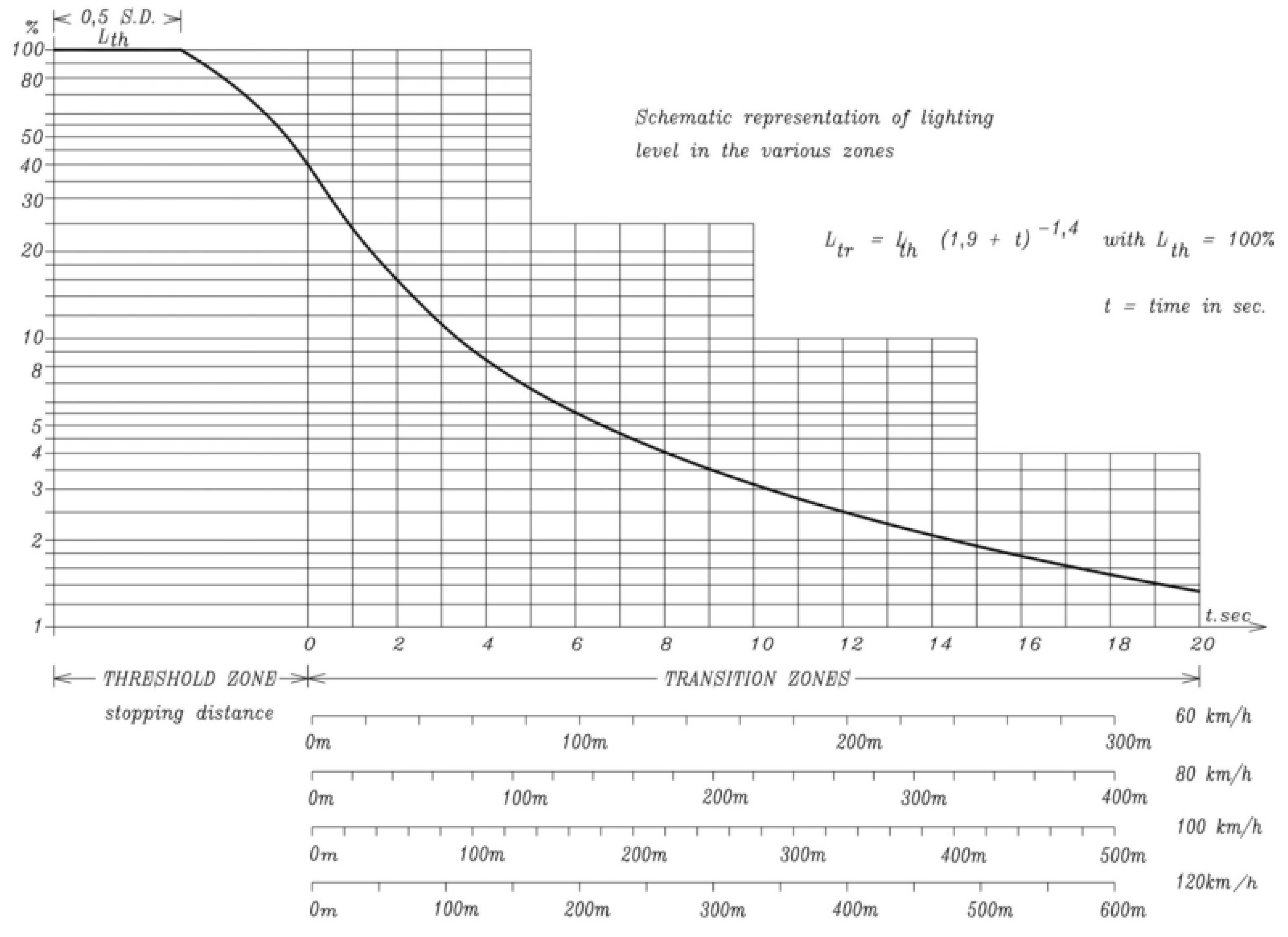
CIE Visual Adaptation Curve and Reduction in Luminance Level

As defined in CIE88:2004, tunnel lighting should meet drivers’ visual requirements and ensure that, in principle, obstacles can be recognized ahead of the stopping distance (SD). Tunnel area is distinguished into different zones to determine the longitudinal level at daytime lighting: access zone, threshold zone, transition zone, interior zone and exit zone. The parting zone is the first part of open road directly after the exit zone and closely related to tunnel lighting. The CIE guide specifies the different lighting requirements for these zones based on several properties of the tunnel in consideration, such as geometric length, linear shape, wall reflectance and traffic volume, etc. The length and luminance level of these zones are suggested here and not repeated for each zone. Typically, luminance levels of threshold and transition zones follow the stepped visual adaption curve, as in Figure 1.
Here, Lth is luminance level at the beginning of the threshold zone. For the first half of the threshold length (≥SD), the luminance level must be equal to Lth, and it is recommended that from the half SD onwards, the lighting level may gradually and linearly decrease to about 0.4 Lth at the end of the threshold zone. Additionally, Ltr is the luminance level of the transition zone as the function of driving time and speed, as in Equation (1).
L t r = L t h 1.9 + t 1.4 ,               L t h = 100 % ,         t 0

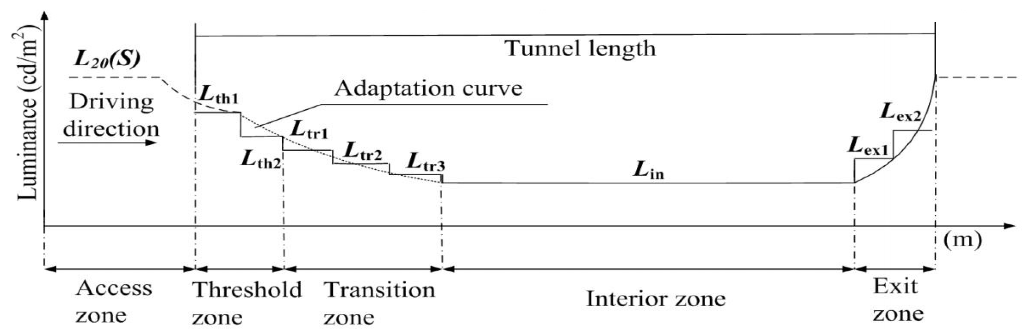
Chinese Guidelines for Tunnel Lighting and Segments of Lighting Area

As defined in the Chinese tunnel lighting guidelines [12], the tunnel lighting area is subdivided into access zone, threshold zone (TH1 and TH2), transition zone (TR1, TR2 and TR3), interior zone and exit zone (EX1 and EX2) as in Figure 2. This is similar to the CIE guide, but many differences exist too. In practice, the segmentation of these zones is flexible in scale in accordance with different tunnel properties (especially tunnel length) and design requirements. Normally, the following rules about zone segmentation and luminance reduction will be followed, and specific requirements definitely need to be considered for scenarios not covered in these guidelines.
Before this, one vital parameter, L20(S), should be given a clear explanation. L20(S) is the reference parameter to be used by subsequent lighting zones. It is measured with an outside luminance detector (Konica Minolta LS-100) at the reference point that is in principle located in the center of the approaching lanes with 1.5 m height and a distance equal to the stopping distance ahead of the tunnel entrance, as in Figure 3. This detector should have a luminance range as wide as 1~7000 cd/m2 with 0.1 cd/m2 resolution and IP65 protection level, it senses the outside light conditions and reports the luminance level at the stopping distance with a 20° field of view opposite the tunnel entrance.
(1). 
Daytime, threshold zone: luminance level and length.
L t h 1 = k L 20 S
L t h 2 = 0.5 k L 20 S
D t h 1 = D t h 2 = 1 2 1.154 D s h 1.5 t a n 10 o .
The key to this equation is as follows:
k, luminance reduction coefficient of threshold zone.
Lth1 and Lth2, luminance level of TH1 and TH2.
Ds, stopping distance.
Dth and Dth2, length of TH1 and TH2.
h, headroom of tunnel entrance.
(2).  
Daytime, transition zone: luminance level and length are defined in Table 3.
(3).  
Daytime, interior zone: luminance level and length are defined in Table 4 and Table 5 respectively.
(4).  
Daytime, exit zone: luminance level and length are defined in Table 6.
(5).  
Nighttime, access or parting zone, luminance level and length.
There is no uniform lighting regulation in the nighttime for the area ahead of the tunnel entrance and out of the tunnel exit, this regulation varies case by case as listed in Table 7.
(6).  
Nighttime, inside tunnel, luminance level and length.
When the luminance level of the outside tunnel drops down to the threshold value, tunnel lighting will switch to nighttime mode from daytime mode, typically the threshold values in normal weather are chosen as Table 8 for Chinese tunnels.
There is no uniform lighting regulation in the nighttime for the area inside the tunnel, this regulation varies according to traffic flow, tunnel length or design speed as shown in Table 9.

2.4. Progress of Tunnel Lighting Control System

The Tunnel Lighting Control System (TLCS) has gone through the stages of centralized control, distributed control and fieldbus control. At present, the fieldbus control system based on industrial ethernet is mostly used in new tunnels.
With the progress of LED lighting technology and production technique, LED lighting technology is widely used in bridge and tunnel construction. Guo Yanwei [19] combined step-less control mode with an LED light source in practice and achieved a 57% energy-saving effect after transforming the traditional extensive lighting control. Wang Yang [20] achieved 18% energy saving via replacing traditional HPSL with LED and improving lighting control from only brightness-based to an intelligent lighting control system with variable color temperature (VCT) and step-less dimming. Encompassing the 22.9 km bridge and 6.7 km tunnel of the main project, as well as the branch project composed of several artificial islands, the whole lighting project of the Hong Kong–Zhuhai–Macao Bridge are all equipped with LED lamps and control systems [21].
Yujie Zhang and Si Li [22] proposed an illumination measurement method of lighting environment based on a RBF (radial basis function) neural network, this method can achieve a rapid and highly precise measurement of the illumination and shows that the relative error between the value predicted by the neural network and the actual value according to the illuminance meter is less than 8%.
Li Qin and Li-Li Dong [18] propose an intelligent control method for tunnel lighting based on traffic volume under different weather conditions. In the daytime, the luminance of tunnel zones depends on the tunnel exterior luminance, traffic volume and vehicle speed regardless of vehicle presence. In the night, the “vehicle in, light brightens; vehicle out, light darkens” strategy is adopted for the tunnel luminance upon vehicle presence. This method also reduces the average amount of control switching by about 310 times per day, which would extend the system’s service life.
To cope with low reliability of communication transmission, Zezhong Li and Wenjin Liu [23] propose a tunnel monitoring system based on CAN bus LAN to realize the safety monitoring of various environmental parameters and equipment. Depending on the edge computing of CAN bus LAN, this proposal ensures tunnel lighting remains under control even if the backbone network is disconnected. Lambros T. Doulos et al. [24] conducted a creative research project aimed to minimize energy consumption at no cost, this method solved the problems of over-illumination and increased energy consumption due to absence of lighting calculation tools in the initial tunnel design. Combined with the weighted L20 method, this new switching control achieved an average energy saving of 31% for 11 existing tunnels; if LED luminaries are used, this average rises to 62% for the threshold zone.
To enhance the reliability and efficiency of the Aberdeen Tunnel in Hong Kong, Ir Edward W.Y. Mok [25] proposed a replacement plan of TLCS using DALI as the communication interface to flexibly address individual or multiple devices, in addition to redundancy design for the master CPU, power supply and network.
However, all of the above research projects on the reliability of TLCS focus mainly on luminance only, with little care afforded to color temperature, and considering the effectiveness and functions of LED, especially of VCT LED lights, and the fact that there have been many research achievements in the functions of color temperature that act on drivers visual performance [26], it is desirable to study the safety and reliability of TLCS lit by VCT LED lights.

2.5. Influences of Color Temperature on Driver Behavior

2.5.1. Necessity of Considering the Influences of Color Temperature

In the study of light source characteristics, there are no relevant regulations and standards for the color temperature, color rendering and spectrum of tunnel lighting in various countries.
In 2002, David Berson et al. of Brown University discovered the third type of photoreceptor cells in the retina, these nerve cells have different sensitivities to various light wavelengths and peak value is located at 490 nm, this is called citopic vision. Yasukouchi found that lighting color temperature has obvious physiological effects [27]. Studies show that the photobiological effect is sensitive to light of 490 nm wavelength and the corresponding maximum light efficiency is 3850 lm/W. The photobiological effect is closely related to the degree of blue component included in the light source, the relationship between light spectrum and visions are shown in Figure 4 [28,29]. Additionally, Navvab Mojtaba found that human visual acuity depends much on the color temperature of the surrounding lighting, and visual acuity is best when the lighting spectrum has a high color temperature [30].
Based on these research results, the use of lighting driven by light resources with high color temperature will be of great benefit in improving driver visual acuity and reducing lighting energy consumption simultaneously. In order to ensure the safety, comfort and high speed of tunnel driving, it is important to consider the effect of spectral distribution of tunnel lighting on driver vision.
Multiple research teams have carried out many experiments on the properties of LED lights sources, especially on the relationship between luminance level, color temperature, and CRI with driver recognition on target objects. Two typical datasets are shown in Figure 5 and Figure 6.
(1)
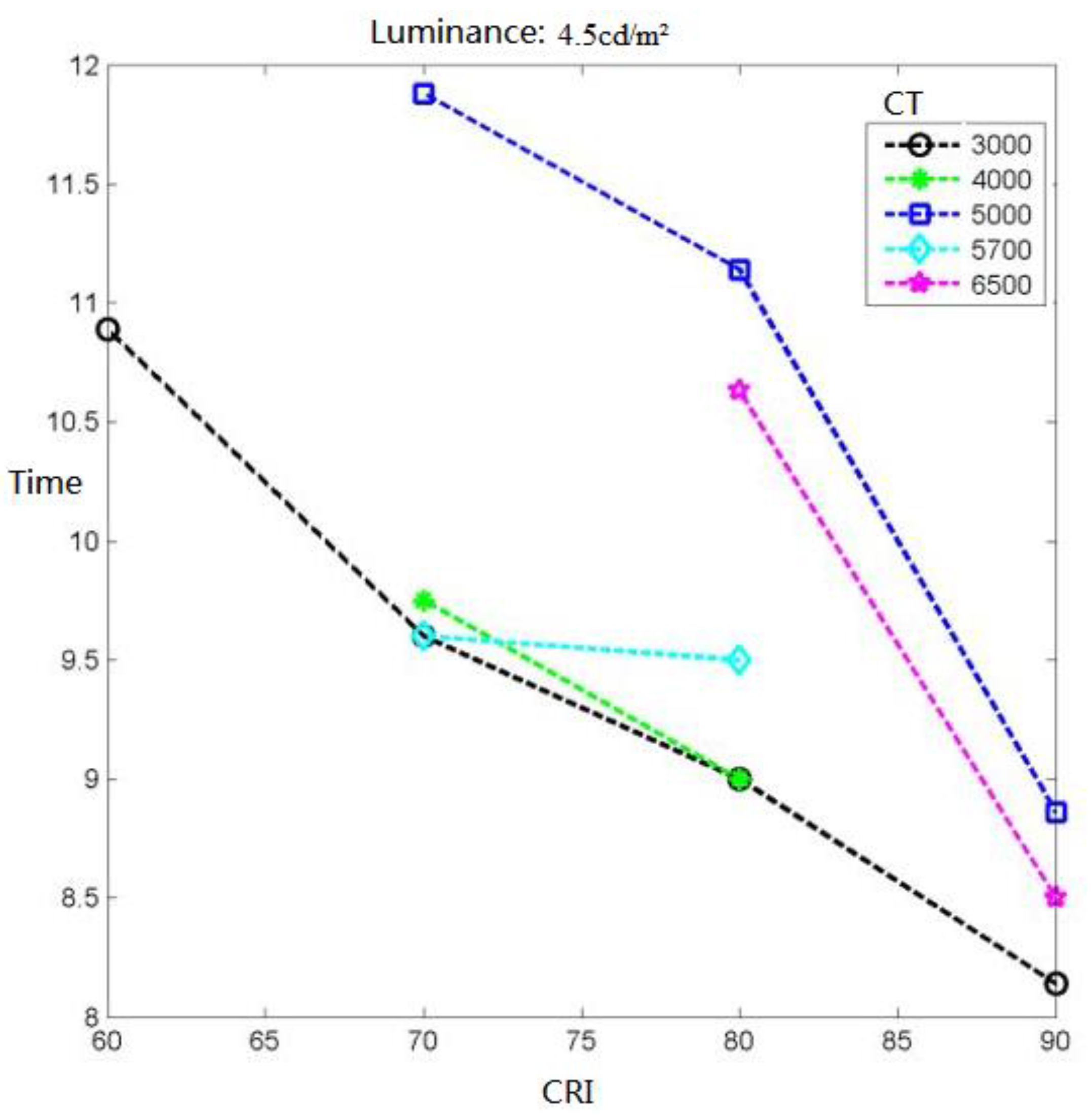
With the increase in luminance level and CRI of light sources, driver visual performance relating to target objects is improved, which proves that in practical engineering it is an effective energy-saving method to enhance the CRI of light sources, increasing visual visibility without increasing the power of the light sources.
(2)
Given a certain luminance level, yellow light sources with low color temperature 3000~4000 K help to increase the photochromic contrast between target objects and background more than white light sources with high color temperature 5000~6500 K. To some degree, this enhances driver visual acuity and visual performance, and eventually contributes to recognizing target objects more easily.

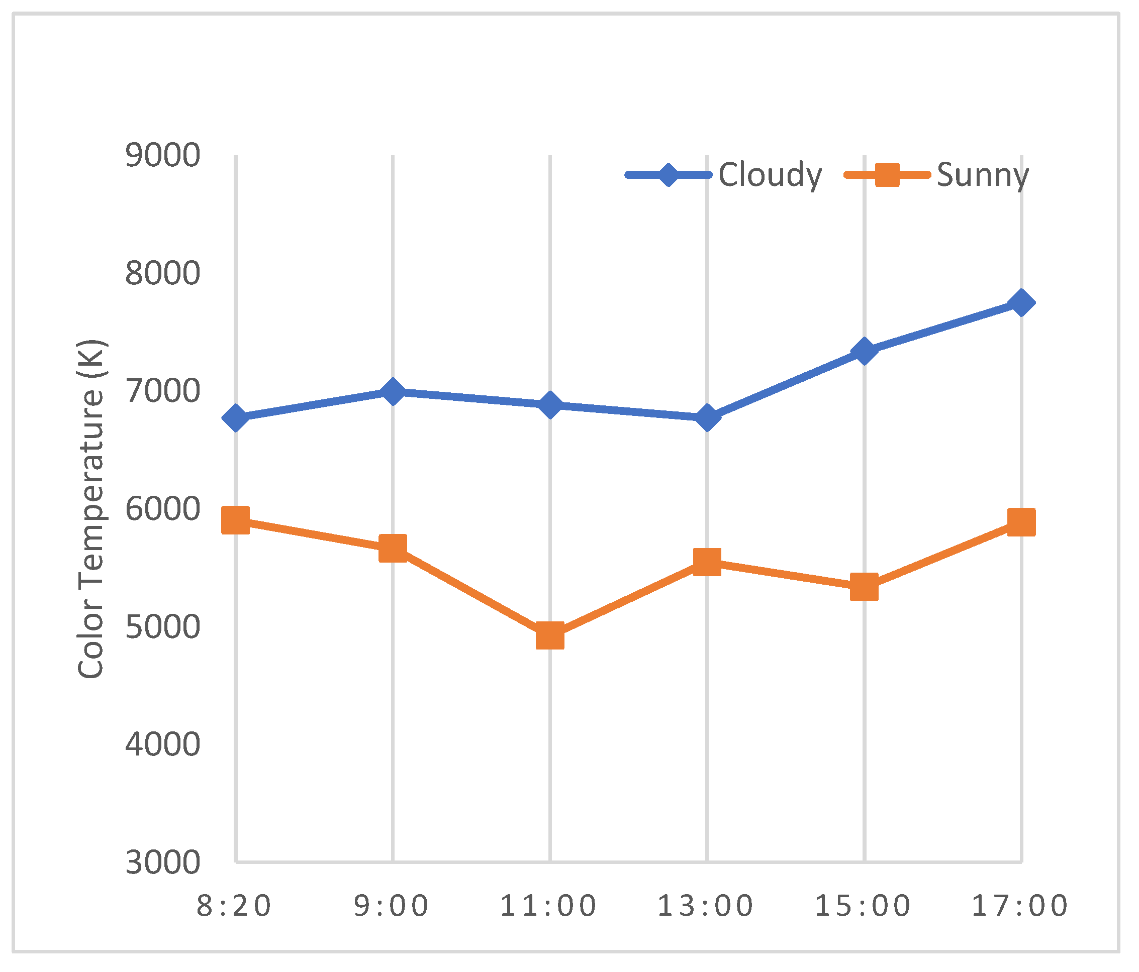
2.5.2. Measurement of Outside Color Temperature

Weather always changes, and so does the color temperature of natural light sources, therefore, dynamic determination of the color temperature outside the tunnel is essential to execute accurate lighting adjustment, so as to achieve an intelligent lighting strategy. If there is no requirement to create close-looped lighting control, acquisition of the color temperature inside the tunnel is optional.
Color temperature can be measured in many ways; in this project, one color luminance meter (Konica Minolta CL-500A) is used, located ahead of the tunnel entrance and close to the luminance detector. This meter acquires color measurements frequently and these can be fetched by user as requested.
In this way, research groups have collected much data on natural light conditions. Here, we present one example of color temperature records for the same geographic location (30°15′~31° north latitude and 120°20′~121° east longitude) that were measured every 2 h (8:00 a.m.~17:00 p.m.) on sunny and cloudy days. When sunny (cloud coverage below 0.3), the color temperature is lower than 6000 K. When cloudy (cloud coverage above 0.8), the color temperature is about 6000~8000 K and it changes relatively little. Compared to cloudy days, on a sunny day the scenery is illuminated by direct sunlight that is yellow in color. At this location, the color temperature of sunny days is lower than that of cloudy days. Figure 7 shows the process of color temperature change under two weather conditions.

3. Reliability of Tunnel Lighting System

3.1. Definition and Objectives of Reliability

A system is a collection of components, the system reliability depends on the type or number of components, the reliability of components, and also how they are connected [31].
The reliability research into traditional tunnel lighting systems includes the hardware, software and management factors of the lighting system, covering both the reliability guarantee and standard establishment in the initial construction stage of the system, and the reliability maintenance and improvement in the operation and maintenance stage, which lasts the whole life cycle of the lighting system. The methods to improve the reliability of general systems, such as the backup mechanism, redundancy mechanism and changing the series–parallel connection relationship of the system components, are also of significance to the reliability research into tunnel lighting systems. However, due to the significant differences between tunnel lighting systems and most control systems, and given their great impact on traffic safety together with the high maintenance costs, the reliability research into tunnel lighting systems needs to comprehensively consider multiple factors including technological advancement and scalability, ease of maintenance, sustainable development and long-term economy. Table 10 describes the key features and objectives of a highly reliable tunnel lighting system.

3.2. Main Problems of Existing Tunnel Lighting Modes

According to the relevant literature and engineering practices, tunnel lighting modes have gone through the fixed lighting mode, time-series-based lighting mode, initially intelligent lighting mode with adjustable luminance, and intelligent lighting mode with variable color temperature and luminance, and these are featured in Table 11.
In practice, each of the above modes has some issues to varying degrees, such as:
  • Some modes pay too much attention to saving energy.
  • Some modes take less care in handling equipment failures.
  • In most cases, tunnel operation relies heavily on the field experience of the operation manager without sufficient theoretical support.
  • In most cases, inadequate attention is paid to monitoring whether the inside lighting adjustment is accurately performing as the preset dimming strategy expects.
  • There is still insufficient emphasis on the reliability of lighting systems.

3.3. Dilemma to Balance Reliability and Sustainability

With the evolution of tunnel lighting sources and control systems, together with the increasing complexity of current traffic conditions, the dependence of tunnel drivers’ visual efficiency on lighting quality is further increased. The reasons listed above cause a rough transition between inside and outside light environments; this cannot satisfy the demand for the safety and comfort of tunnel drivers in real time. Lighting safety has always been challenging in the improvement of tunnel lighting system.
As A. Peña-García [32] points out, tunnel lighting is considered a paradoxical matter for two main reasons: firstly, complexity of driving in tunnels makes it almost impossible to create an installation satisfying all the potential users, and secondly, tunnel lighting is extremely expensive in economic, energy, environmental and even social terms. Safety and sustainable consumption have been somewhat inverse concepts in tunnel lighting. However, it was until the last decade that groups around the world seriously started to create reliable models and proposals to decrease the negative impact of these lighting installations while maintaining road safety in tunnels.
Building a tunnel lighting system with coordinated reliability and sustainability and ensuring tunnel driving safety is one of the core tasks of TLCS. The main measures include the improvement of tunnel lamps and the enhancement of reliability of TLCS. At present, in terms of tunnel lamps, good results have been achieved through the large-scale deployment of LED lights. Additionally, reliability improvement of TLCS is mainly brought about by the intelligentization and informatization of lighting control systems.

3.4. Reliability Evaluation of Tunnel Lighting System

How can we evaluate the quality of tunnel lighting? Perhaps some enlightenment can be obtained from the perspective of the reliability requirements of modern control systems.
Based on system reliability theory, no matter how many components the system contains or how the components are connected, the system reliability Ra can be deduced mathematically from Equations (5) and (6),
R a = i = 1 n R i               i = 1 , 2 , n
R a = 1 i = 1 n F i = 1 i = 1 n 1 R i     i = 1 , 2 , n .  
Here, Equations (5) and (6) are for a series system and parallel system, respectively. Ra denotes the system reliability, Fi is the ith unit unreliability; Ri is the ith unit reliability.
For a hybrid system, its reliability can be calculated via Equations (7) and (8), which are actually derived from Equations (5) and (6):
  • Hybrid series–parallel system: assume that the system is n level in series, and each level is j level in parallel,
    R a = j = 1 n 1 i = 1 m j 1 R i j .  
  • Hybrid parallel–series system: assume that the system is m level in parallel, and each stage is j level in series,
    R a = 1 i = 1 m 1 j = 1 n i R i j .
In this case, the task of improving the reliability of TLCS is transformed into how to maximize Ra.

3.5. Reliability Model Created in This Research

In this study, the reliability model discussed stems from one tunnel lighting system with the same framework as [13], the reliability block diagram (RBD) in Figure 8 can be used to analyze its system reliability.
For a reliability analysis of the whole system, this TLCS is subdivided into three series subsystems or components; the lighting environment sensing component (LESC) is the component used to sense outside lighting conditions and report this collected light data to the tunnel system manager (TSM) in which the intelligent lighting adjustment strategy resides. Each tunnel onsite manager (TOM) receives and parses lighting adjustment commands (LAC) from TSM, then executes the adjustment of lighting parameters (inside luminance and color temperature). The system reliability is denoted as Equations (9) and (10),
R = RLS × RSM × ROM
ROM = ROM1 × ROM2 × … ROMn.
Here, RLS, RSM, ROM and ROmi (i = 1, 2,… n) denote the reliabilities of LESC, TSM, TOM superset and TOM units individually.
For each component, its reliability is evaluated by the embedded hardware and software entities. For example, lighting environment sensing devices, LED lights, lighting parameters modulators, and communication cables (LAN/RS485/Serial) are all hardware entities, whose reliabilities are basically determined at the stage of installation, mainly by respective manufactures. The influence factors for these will not be given more explanation since this is not the core topic in this paper.
Of all the software entities, the intelligent adjustment strategy module (IASM) is the main software entity, its major functions or customer requirements are as listed in Table 12.
The quality and reliability of IASM impact the whole tunnel lighting quality most significantly and determine whether the whole system meets customer requirements with reasonable performance and high confidence, so these are the key factors for the whole control system and thus the core object of this study.
As can be seen from Equations (5) and (6), this TLSC is a system formed in series by LESC (Level-1, RLS), TSM (Level-2, RSM) and TOM (Level-3, ROM). RLS and ROM are basically determined by the production of relevant hardware manufacturers or integrators and the reliability of configuration software. As the integrator of the overall TLCS, our main efforts are focused on the second level (TSM, mainly IASM) to improve the reliability level of this software system as a whole.

4. Theoretical Basis for ANNs to Improve Lighting System Reliability

4.1. Brief of ANNs

Artificial neural networks (ANNs), also referred to as neural networks (NNs) or connection models (CM). ANN is a modeling technique and algorithmic mathematical model that imitates the behavior characteristics of human neural networks and performs distributed and parallel information processing. ANNs are able to establish empirical relationships between independent and dependent variables and extract subtle information and complex knowledge from representative data sets [33]. Depending on the complexity of the system, the network achieves the purpose of processing information by adjusting the connection relationship among a large number of neurons. ANNs can be categorized from different classification criteria as shown in Table 13.

4.2. Feasibility of Lighting Control Aided by ANNs

In certain tunnel areas, natural light characteristics are mainly related to latitude and longitude, entrance locations, angle of the sun, season, weather, time periods, cloud layer, atmospheric transparency, ground reflection ability, surrounding vegetation and other natural factors. These characteristics follow certain statistical regularity and strong seasonality. The outside illuminance is heavily influenced by these natural factors. On sunny days, outside illuminance fluctuates significantly and changes from moment to moment. When cloudy (cloud coverage is 0.8–1), the illuminance changes relatively gently. The outside color temperature is comparatively stable, especially on cloudy and foggy days, and color temperature changes gradually. When sunny, the color temperature varies from low to high and then to low, its peak usually appears at about midday, although sometimes it is fairly high near the morning and evening.
The essence of the tunnel lighting system is to seek a smooth transition and easy adjustment between natural light and artificial lighting through the variation of luminescence parameters of the tunnel luminaries so as to guarantee driving safety and comfort. If the natural light changes in a regular manner, then the controllability of artificial lighting will be of high confidence.
Supervised learning neural networks can find the intrinsic distribution law of known label data by analyzing this large number of labels and fitting with some specific laws. The trained neural network model can be used to predict the reasonable output of other input data.
During the training of the neural network, the data labels of the input layer and output layer can be constructed by collecting the actual light sensing data, targeting the inside lighting parameters and tunnel attributes (bidirectional or unidirectional, design speed, design traffic volume, etc.). Through the study of this large collection of data labels, if the lighting neural network can achieve an ideal fit to the actual lighting control system, then the predicted value of the simulation network can be used as the setting parameters of the actual lighting control system.

4.3. Parametric Characteristics of Tunnel Lighting System

Based on the comparison and analysis of the above mainstream lighting modes, one VCT lighting control system is chosen as the research object. This system comprehensively considers the influence of multiple input factors, and the output contains two parameters, color temperature and luminance, that is, the input and output can be conceptually expressed as the following function,
I C T = F u n 1 D i r e c t i o n ,   W e a t h e r ,   V o l u m e ,   O C T ,   O L u m i n a n c e ,   S p e e d
I L u m i n a n c e = F u n 2 D i r e c t i o n ,   W e a t h e r ,   V o l u m e ,   O C T ,   O L u m i n a n c e ,   S p e e d
This lighting system is, therefore, a multiple-input and multiple-output (MIMO) control system. Input and output parameters are described in Table 14.

5. Model Training of Tunnel Lighting ANN

5.1. Process of Model Training

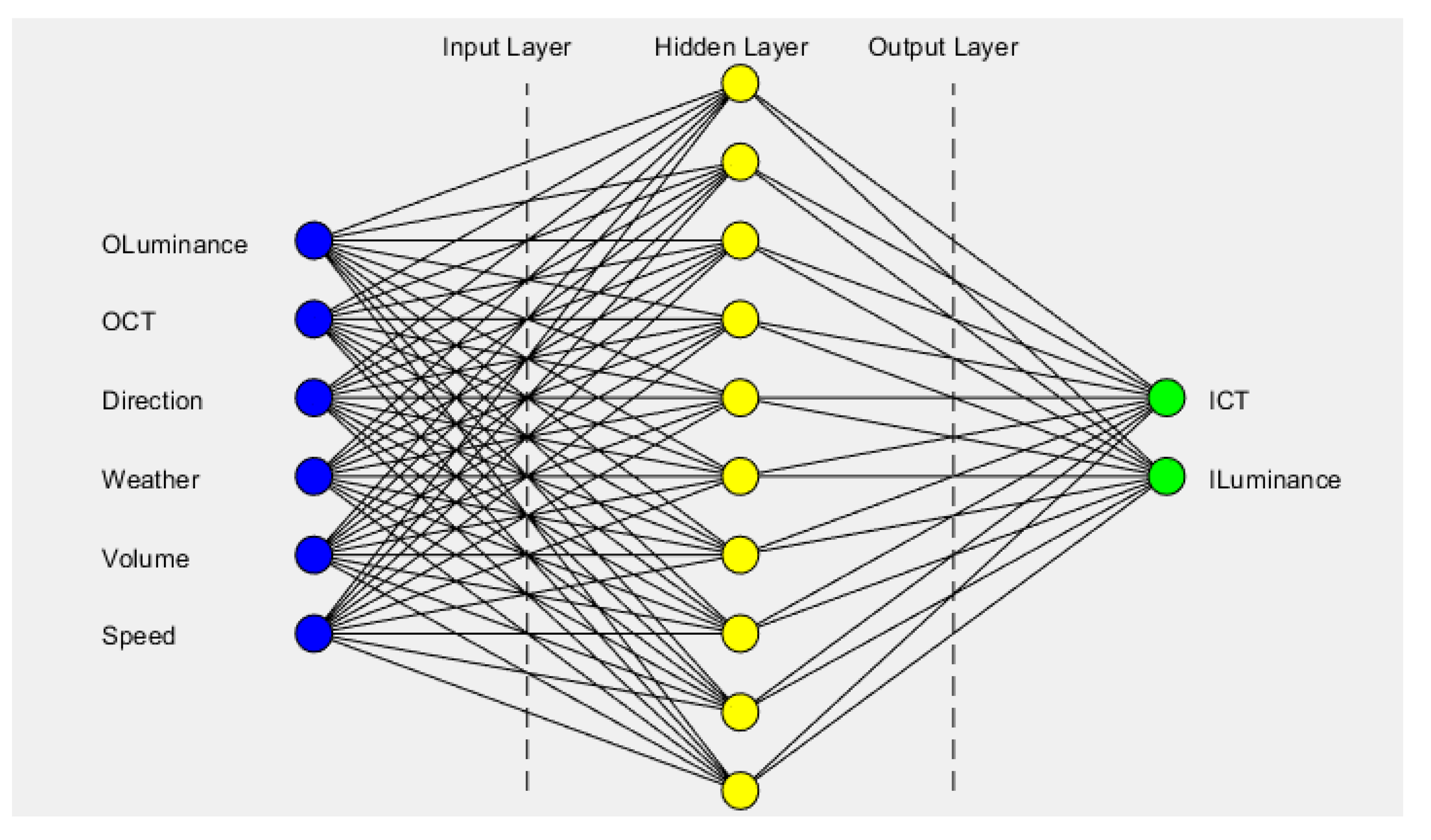
5.1.1. Model Simplifying and Parameters Preprocessing

Based on the description in Table 14 and combined with the regulation strategy of the VCT lighting system, if the outside light sensing data and inside target lighting settings of the actual system are directly fed into the training process of the neural network, this process will present the following characteristics:
  • Six input-layer parameters and two output-layer parameters are distributed in a wide range without uniform units.
  • Both input- and output-layer parameters are mixed types of discrete and continuous parameters.
  • Various parameter types and numerical ranges have an unbalanced influence on the link weights of network neurons and often cause the jitter of training process.
In order to alleviate this type of imbalance and divergence, it is essential to preprocess the parameters. For a particular tunnel, after the completion of the scheme design and construction, the input parameters affecting the regulation of the lighting system have the following characteristics:
  • Direction is determined, either unidirectional or bidirectional.
  • Design traffic volume is determined.
  • Design speed is determined.
  • The target lighting parameters do not fluctuate obviously under the influence of the three above parameters, but are deeply affected by real-time weather, OCT and O Luminance.
As such, the input-layer characteristics can be simplified into three parameters. Output parameters need no simplification.
In addition, in view of the fact that the input-layer and output-layer parameters contain the mixture of discrete and continuous parameters, the discrete parameters need to be handled via a one-hot or embedding algorithm.
According to the regulation strategy, since other lighting zones are converted by referring to the threshold zone, subsequent processing will more or less inherit the parameters of the threshold zone. Therefore, this preprocessing and normalization of the input and output parameters in the lighting network is exemplified with the threshold zone data, as in Table 15.
After this process, with each group of input and output data from the actual lighting system, data labels should be ready to train the lighting network, and these data will be fed into the below network to execute this training process as shown in Figure 9.

5.1.2. Training Experiments

In this research, the actual lighting regulation scenario under normal weather conditions, unidirectional tunnel, design speed 80 km/h, and traffic volume 380 [veh/(h·ln)], is firstly selected to define and train the lighting neural network. However, since the fitting degree of this neural network architecture with regulation strategy is not a priori, it is necessary to compare the topologies of different neural networks (mainly referring to the number of hidden layers or number of neurons in each hidden layer) under this scenario.
The training process is briefly described below:
(1)
After one-hot processing, input and output parameters are both transformed into 3-degree data.
(2)
Before training starts, 2000 data labels are divided into 1500 training sets, 300 test sets, and 200 validation sets.
(3)
When training with Matlab, a neural network is created with the following statement:
net = newff(‘train_input’, ‘train_output’, [10, xx, xx], {‘logsig’}, ‘traingdx’)
where, ‘train_Input’ and ‘train_out’ are each 1500 × 3 arrays, formed by 1500 training sets. ‘logsig’ is the transfer function (Logarithmic sigmoid transfer function). ‘traingdx’ as the training function (gradient descent with momentum and adaptive learning rate backpropagation).
(4)
Training parameters are set as in Table 16.
(5)
In this premise, different attributes of the hidden layer are adjusted, and two groups of tests are performed, as Table 17 and Table 18 denote.
Experimental data of above two groups of tests are summarized as follows:
(1)
When the number of hidden layers (depth) is extended, with increase in this number, network regression result and fitting degree of luminance and color temperature are basically similar, with no significant changes, but they can all meet the fitting target of color temperature and luminance (R > 0.995).
(2)
When the dimension of hidden layer is extended (1 hidden layer is maintained), the regression change is not obvious when the number of neurons is greater than five (both are greater than 0.995). However, when the number of neurons is 10, the fitting degree of luminance and color temperature is better than that when the number of neurons is 5 or 20. Especially in the case of low luminance label, the deviation degree of fitting is better than the other two cases.
(3)
In the two tests, the fitting between the actual luminance of the lighting system and the predicted value of the trained neural network basically meets the following function (Equation (14)), that is, the predicted and actual values basically conform to unary linear regression with only slight deviations for a and b.
O u t p u t = a T a r g e t + b
(4)
Both tests achieved a 100% recognition rate for color temperature.

5.1.3. Training Results

Based on above findings, this neural network is determined to be composed of one input layer (three neurons), one hidden layer (ten neurons) and one output layer (three neurons), hence the topology of this network is defined as in Figure 10.
This training algorithm achieved the regression results as Figure 11.
For this trained network model, partial network parameters are listed below as examples.
(1). Net.IW{1, 1}, weigh matrix [10 × 3 array] denotes that the 10 branch extends from the input layer to the hidden layer.
N e t . L W 1 ,   1 = 5.3781 1.0433 2.0605 5.7211 1.0239 1.9557 1.4488 0.4322 5.6562 2.6351 4.0524 3.3387 2.1650 3.0634 4.6949 0.2097 5.7442 1.8147 2.5098 3.6840 4.2226 1.1691 5.1603 2.8807 2.3365 3.8057 3.6902 2.6272 2.5205 4.7722
(2). Net.LW{2, 1}, weigh matrix [3 × 10 array] denotes the 10 branch extends from the hidden layer to the output layer,
N e t . L W 2 ,   1 = 0.5353 0.3432 0.5064 0.1871 0.5203 1.2990 0.7075 0.2314 0.4373 0.3569 0.1496 0.4584 0.0034 0.0715 0.7165 0.7255 0.2559 0.4072 0.0136 0.2855 0.0567 0.1969 0.1597 1.3025 0.3998 0.5415 0.7245 0.1825 0.1567 0.6083
(3). Net.b{1, 1} and Net.b{2, 1} are biases of net as follows:
N e t . b 1 ,   1 = 6.1421 , 4.5574 ,   3.5756 , 2.2180 ,   0.5487 ,   0.6914 ,   1.7774 , 3.1605 , 4.9226 , 6.0615
N e t . b 2 ,   1 = 0.5841 , 0.5014 , 0.5466

5.2. Simulation Analysis

After this, the lighting neural network training is completed, and the dimming results of the actual system should be used to verify whether overfitting happens with the training model.
Songshan tunnel lighting system [13] has accumulated quantities of field data since its online operation. In this simulation, data labels are constructed based on the light sensing data and control records of target luminance and color temperature in the threshold zone for 12 h continuously from 6:00 to 18:00 in normal weather, with a sampling period of 10 min, and then these labels are used to verify the validity of this lighting neural network.

5.2.1. Simulation of Inside Luminance

This simulation result in Figure 12 shows the following:
(1)
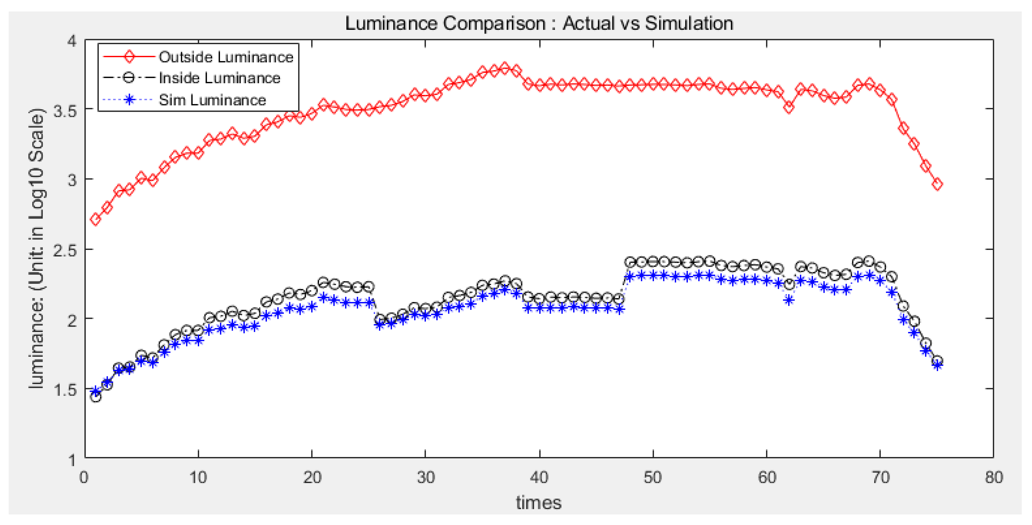
The prediction of this training model is basically consistent with the regulation of the actual lighting system with a high degree of fit.
(2)
The prediction curve of this training model is comparatively flatter than that of the actual lighting system, which effectively weakens the luminance jitter at the moment of dimming.
(3)
Except for the dimming moments when outside illuminations are fairly low, the predicted values of this training model are lower than the actual outputs of this lighting control system, which helps to achieve a smooth transition between dimming moments and indirectly reduce the energy consumption.
(4)
Actual and simulation luminance curves shift slightly at the moment when color temperature transitions between 6000 K and 3500 K; this is because different L20 luminance reduction coefficients are assigned in the actual lighting strategy to make up for color temperature fluctuation in the daytime under normal weather conditions. Meanwhile, since the target lighting parameters are possibly adjusted in multiple steps, a large gradient change in luminance or color temperature is subdivided into several time slices with smaller granularity in each regulation period, which effectively weakens the harm to visual comfort that large gradient luminance or color temperature jitter may cause.

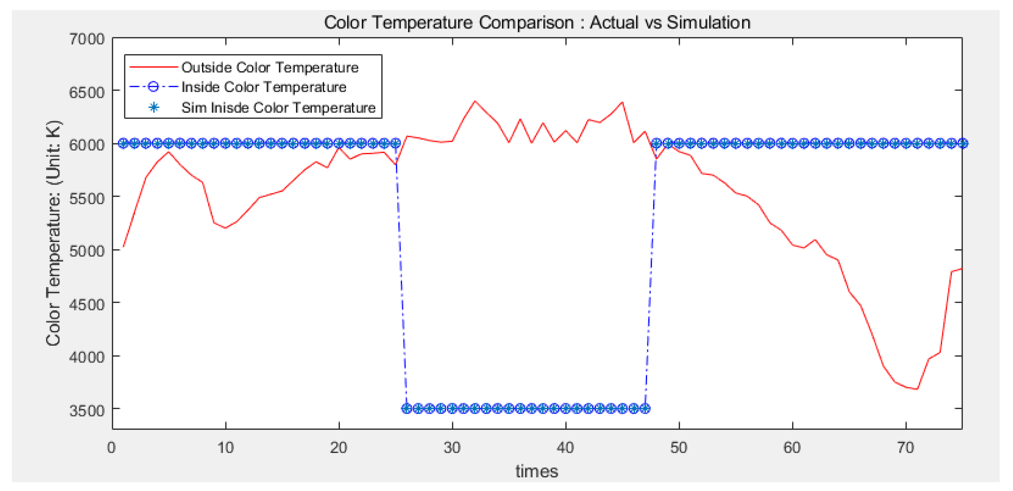
5.2.2. Simulation of inside color temperature

This simulation result in Figure 13 shows the following:
(1)
Actual inside color temperature of the threshold zone is 100% consistent with the prediction of the training model, that is, the color temperature classifier has a 100% recognition rate.
(2)
In this variable color temperature lighting regulation strategy, the color temperature of the threshold zone only switches among limited enumerated values (3500 K and 6000 K). If the actual color temperature needs to be changed (for instance, from 3500 K to 4000 K), the corresponding network model can be trained and switched instantly.
(3)
With the co-training process of color temperature recognition as a discrete parameter and luminance fitting as a continuous parameter, color temperature classification recognition and luminance fitting maintain relative independence and have no adverse impact on each other.
(4)
Color temperature transitions twice between 6000 K and 3500 K, 3500 K lasts roughly for the midday duration. During this time window, drivers are prone to struggle with visual fatigue; this transition of color temperature between the threshold zone and open space greatly helps to stimulate drivers’ excitement and make them concentrate on driving carefully, keeping the driving process safe and smooth in the tunnel area.

6. Discussion

Since its completion of the training, this network model has worked in parallel with the physically deployed TLCS for more than 12 continuous months, and this model works stably.
When the color temperature and luminance of LED lamps are altered as intelligent lighting strategy requires, prediction values from this network model also meet the requirements to drive this TLCS work in the same way. If this network model is to run separately, it should be working as well as this physical TCLS. Indeed, in several daytime testing scenarios when this network model operated alone, the artificial light environment of each tunnel zone offered an adequate visual cognition distance for driving safety and comfort, the lighting indexes met expected lighting specifications, internal traffic flow ran smoothly and no obvious speed variability took place, feedback from actual drivers also indicated lighting quality satisfied visual performance for driving safety with little visual discomfort induced.
Before this network model is introduced, this physical TLCS works with reliability index 0.95, that is Ra = 0.95, this new Ra is much improved in the parallel system:
Ra’ = 1 − (1 − Ra) × (1 − Ra) = 0.9975.

6.1. Evaluation of This Network Model

The above neural network definition and training is based on the TLCS under normal weather conditions when the design speed is 80 km/h and traffic volume is 380 [veh/(h·ln)]. Training results show that this network model can achieve 100% color temperature recognition and a high fitting degree of luminance. Moreover, several groups of experimental data indicate that the predicted and actual values of inside luminance follow unary linear regression with high degrees of fitness.
This training algorithm can be derived to other tunnel lighting scenarios, such as different tunnel direction categories, weather conditions, design speeds, and traffic volumes, etc. It only needs to construct corresponding data labels with the actual input and output data of different scenarios, and the training process and parameter configuration are roughly the same.
Of course, if other influencing factors in tunnel lighting are considered, such as exhaust fumes in the tunnel, air visibility, or vehicle type, etc., only the dimension of the input layer of the neural network should be extended.
Therefore, the aforementioned network training model has good scalability and adaptability, and can be used as a reference mode for other lighting scenarios.

6.2. Application of This Network Model

(1). For the tunnel lighting system that has been in actual operation, the trained neural network model can run in parallel with the actual lighting control system to realize the parallel verification function.
(2). For the tunnel lighting system that has been in actual operation, the trained neural network model can partially replace the physical lighting control system when the line fault of the lighting control system occurs.
(3). For tunnel cluster systems that meet certain conditions (artificial lighting systems between different tunnels do not influence each other, climate and natural light conditions are relatively close), the trained neural network model and physical lighting control system can be deployed in different tunnels in an alternating or hybrid manner. Such deployment can reduce the cost of installation and maintenance of light sensing equipment and tunnel control lines, and also improve the overall economy of tunnel cluster systems.
(4). If artificial lighting sensing modules are added inside the tunnel, deviations between actual lighting parameters (actual color temperature and luminance) and predicted values of this network model (predicted color temperature and luminance) can be tracked dynamically. When these deviations exceed a certain limit, early warnings are a great help in reporting and diagnosing the failure of lighting fixtures, line failures, or other equipment malfunctions in a timely manner. Additionally, if target lighting parameters can be adjusted rapidly to compensate for this probable degradation of lighting quality caused by these deviations, there will be great benefits from this quasi closed loop lighting control.

7. Conclusions

Taking one online physical lighting control system as a reference, this study designs and trains one lighting neural network model to simulate and realize the corresponding functions that the physical system has accomplished. Unlike many existing lighting control systems or neural network models in which only inside luminance is adjusted or trained, this model takes into consideration both inside luminance and color temperature by means of feeding them into output layer parameters, this simulation matches the physical VCT lighting control system with a high degree of fitness, that is, inside color temperature achieves a 100% recognition rate and inside luminance conforms to unary linear regression with smoother fitting curve. Therefore, this model has wider practicability and applicability, which is of great help to enhance the reliability of this VCT lighting control system. Because this network model is able to work alone or work in parallel with the physically deployed TLCS in cross-check mode, the whole system will definitely gain higher reliability than before.
To some extent, this study proves the technical feasibility of a lighting neural network to replace the physical lighting control system, which is an effective exploration to improve the level of intelligence of a tunnel lighting control system. With the long-term operation of the physical tunnel lighting system, it is certainly necessary to use the large amount of lighting data collected at the tunnel site to continuously calibrate or optimize this network model, enhance its robustness and prevent the over-fitting problem of this lighting neural network. Additionally, due to its attribute of continuous learning and strong scalability as a software system, this model has the incomparable advantages that a physical lighting control system lacks, providing a new idea to improve the reliability of the lighting control system.

Author Contributions

The authors confirm the contributions to the paper as follows: study conception and design, B.S. and J.H.; data collection, B.S. and J.H.; analysis and interpretation of results, B.S., J.Z. and R.W.; draft manuscript preparation, B.S., R.W. and J.Z. All authors have read and agreed to the published version of the manuscript.

Funding

This work was partly supported by the scientific research project of Fujian Expressway Science & Technology Innovation Research Institute Co., Ltd. and partly by the traffic scientific research project of Department of Transport of Shaanxi Province (No. 21-02X).

Institutional Review Board Statement

Not applicable.

Informed Consent Statement

Not applicable.

Data Availability Statement

Data generated in this study are available upon request.

Acknowledgments

The authors would like to thank all of the participants for attending the experiments.

Conflicts of Interest

The authors declare no conflict of interest.

References

  1. Ministry of Transport PRC. Statistics Report of Transportation in China. 2022. Available online: https://xxgk.mot.gov.cn/2020/jigou/zhghs/202205/t20220524_3656659.html (accessed on 25 May 2022).
  2. 2019 Road Traffic Accident Statistical Annual Report of the People’s Republic of China; Traffic Management Bureau of the Ministry of Public Security: Beijing, China, 2020.
  3. Zhang, X.Q.; Hu, J.B. Analysis of theory for highway tunnel lighting set and evaluation method situation. Highway 2016, 61, 5. [Google Scholar]
  4. Pervez, A.; Huang, H.; Han, C.; Wang, J.; Li, Y. Revisiting freeway single tunnel crash characteristics analysis: A six-zone analytic approach. Accid. Anal. Prev. 2020, 142, 105542. [Google Scholar] [CrossRef]
  5. Shy, B. Overview of traffic safety aspects and design in road tunnels. IATSS Res. 2016, 40, 35–46. [Google Scholar]
  6. From Torches to LED Fixtures, Explore the History and Future of Tunnel Lighting. Available online: https://www.sohu.com/a/166463858_139987 (accessed on 22 August 2017).
  7. Tan, K.Z.; Lee, S.K.; Low, H.C. LED Lifetime Prediction Under Thermal-Electrical Stress. IEEE Trans. Device Mater. Reliab. 2021, 21, 310–319. [Google Scholar] [CrossRef]
  8. Kyak, S.; Gkmen, G.; Koyiit, G. Lifetime Prediction for a Cell-on-Board (COB) Light Source Based on the Adaptive Neuro-Fuzzy Inference System (ANFIS). J. Nanomater. 2021, 2021, 6681335. [Google Scholar] [CrossRef]
  9. Bertin, K.; Canale, L.; Ben Abdellah, O.; Méquignon, M.-A.; Zissis, G. Life Cycle Assessment of Lighting Systems and Light Loss Factor: A Case Study for Indoor Workplaces in France. Electronics 2019, 8, 1278. [Google Scholar] [CrossRef] [Green Version]
  10. Zhang, X.; Hu, J.; Wang, R.; Gao, X.; He, L. The comprehensive efficiency analysis of tunnel lighting based on visual performance. Adv. Mech. Eng. 2017, 9, 1687814017696449. [Google Scholar] [CrossRef] [Green Version]
  11. CIE Technical Committee. Guide for the Lighting of Road Tunnels and Underpasses, 2nd ed.; CIE Technical Committee: Vienna, Austria, 2004. [Google Scholar]
  12. JTG/TD70/2-01-2014; Guidelines for Design of Lighting of Highway Tunnels. Communications Press Co., Ltd.: Beijing, China, 2014.
  13. Su, B.; Hu, J.; Zeng, J.; Wang, R. Traffic Safety Improvement via Optimizing Light Environment in Highway Tunnels. Int. J. Environ. Res. Public Health 2022, 19, 8517. [Google Scholar] [CrossRef]
  14. Van Winsum, W. The Effects of Cognitive and Visual Workload on Peripheral Detection in the Detection Response Task. Hum. Factors 2018, 61, 992–1003. [Google Scholar] [CrossRef]
  15. Roy Choudhury, A.K. Principles of Colour and Appearance Measurement. 2015. Available online: https://www.sciencedirect.com/topics/engineering/light-adaptation (accessed on 30 November 2022).
  16. Liu, C.; Wang, Q. Research on Light-Dark Adaptation of Human Vision in Tunnel Portals. Mapp. Intimacies 2021. ahead of print. [Google Scholar] [CrossRef]
  17. Reyes, M.A.; Gallagher, S.; Sammarco, J.J. Evaluation of Visual Performance When Using Incandescent, Fluorescent, and LED Machine Lights in Mesopic Conditions. IEEE Trans. Ind. Appl. 2013, 49, 1992–1999. [Google Scholar] [CrossRef]
  18. Qin, L.; Dong, L.; Xu, W.; Zhang, L.; Leon, A.S. An Intelligent Luminance Control Method for Tunnel Lighting Based on Traffic Volume. Sustainability 2017, 9, 2208. [Google Scholar] [CrossRef]
  19. Guo, Y.W.; Fu, D.X. Research on comprehensive energy saving technology of ventilation and lighting linkage in highway tunnel. Build. Energy Conserv. 2018, 45, 4. [Google Scholar]
  20. Wang, Y.; Qin, H.B.; Hu, Y.Z. Design of tunnel color temperature lighting control system. Softw. Guide 2018, 17, 157–161. [Google Scholar]
  21. Du, J.; Zhou, S.K.; Chen, C.G. LED lighting technology of Hong Kong-Zhuhai-Macao Bridge lighting project. Zhaoming Gongcheng Xuebao 2020, 31, 11. [Google Scholar]
  22. Zhang, Y.; Li, S. Study on Illumination Measurement Method of Lighting Environment Based on RBF Neural Network. J. Phys. Conf. Ser. 2022, 2196, 012004. [Google Scholar] [CrossRef]
  23. Li, Z.; Liu, W.; Du, Y.; Xu, S. Design of Underground Tunnel Monitoring System Based on CAN BUS Local Area Network. In Proceedings of the 2021 4th World Conference on Mechanical Engineering and Intelligent Manufacturing (WCMEIM), Shanghai, China, 12–14 November 2021; pp. 613–617. [Google Scholar]
  24. Doulos, L.T.; Sioutis, I.; Tsangrassoulis, A.; Canale, L.; Faidas, K. Revision of Threshold Luminance Levels in Tunnels Aiming to Minimize Energy Consumption at No Cost: Methodology and Case Studies. Energies 2020, 13, 1707. [Google Scholar] [CrossRef] [Green Version]
  25. Edward, I.A.; Mok, W.Y. Enhancement of the Lighting and Control System of Aberdeen Tunnel. 2014. Available online: https://www.semanticscholar.org/paper/Enhancement-of-the-Lighting-and-Control-System-of-Edward-Mok/05fa3450a376618dbb30d2bc1358ee098d7e6aba#citing-papers (accessed on 20 June 2021).
  26. Yamamoto, J.; Kobayashi, S.; Nagasawa, T.; Ito, H. Visibility and color-rendering properties of Light sources in tunnel lighting. In Proceedings of the 26th Session of CIE (Volume 2), Beijing, China, 4–11 July 2007. [Google Scholar]
  27. Yasukouchi, A.; Ishibashi, K. Non-visual Effects of the Color Temperature of Fluorescent Lamps on Physiological Aspects in Humans. J. Physiol. Anthropol. Appl. Hum. Sci. 2005, 24, 41–43. [Google Scholar] [CrossRef] [Green Version]
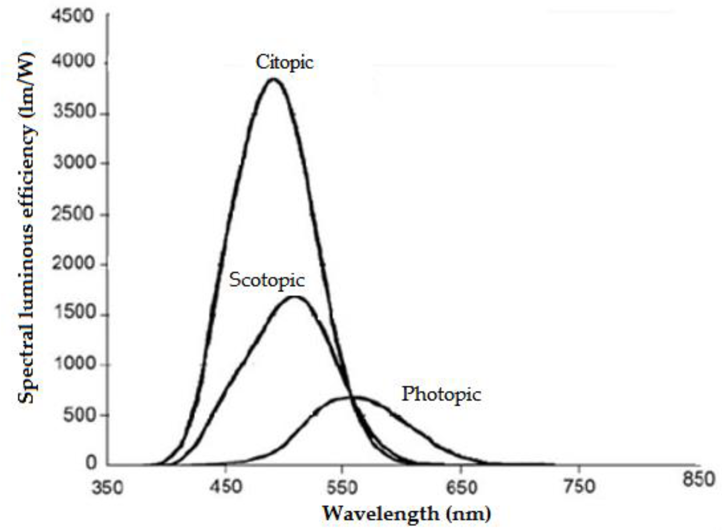
  28. Chen, Z. Study on Road Lighting Safety with Citopic. China Illum. Eng. J. 2007, 18, 31–34. [Google Scholar]
  29. Berman, S.M.; Clear, R.D. Past vision studies can support a novel human photoreceptor. Light Eng. 2008, 16, 88–94. [Google Scholar]
  30. Navvab, M. Visual Acuity Depends on the Color Temperature of the Surround Lighting. LEUKOS J. Illum. Eng. Soc. N. Am. 2002, 31, 70–84. [Google Scholar] [CrossRef]
  31. Putcha, C.; Dutta, S.; Gupta, S.K. System Reliability. In Reliability and Risk Analysis in Engineering and Medicine (Transactions on Computational Science and Computational Intelligence); Springer: Cham, Switzerland, 2021. [Google Scholar] [CrossRef]
  32. Peña-García, A. Sustainable tunnel lighting: One decade of proposals, advances and open points. Tunn. Undergr. Space Technol. 2022, 119, 104227. [Google Scholar] [CrossRef]
  33. Park, Y.-S.; Lek, S. Chapter 7-Artificial Neural Networks: Multilayer Perceptron for Ecological Modeling. In Developments in Environmental Modelling; Elsevier: Amsterdam, The Netherlands, 2016; Volume 28, pp. 123–140. [Google Scholar] [CrossRef]
Figure 1. CIE luminance evolution along the tunnel [11].
Applsci 13 00042 g001
Figure 2. Tunnel lighting system subsection and demand luminance curve [18].
Applsci 13 00042 g002
Figure 3. Determination of outside luminance ahead of tunnel L20(S).
Applsci 13 00042 g003
Figure 4. Photopic, scotopic and citopic.
Applsci 13 00042 g004
Figure 5. Recognition time with CRI and color temperature (luminance: 2 cd/m2).
Applsci 13 00042 g005
Figure 6. Recognition time with CRI and color temperature (luminance: 4.5 cd/m2).
Applsci 13 00042 g006
Figure 7. Color temperature changes with weather condition.
Applsci 13 00042 g007
Figure 8. Reliability block diagram of TLCS.
Applsci 13 00042 g008
Figure 9. BP network layers, inputs and outputs.
Applsci 13 00042 g009
Figure 10. Structure of lighting neural network.
Applsci 13 00042 g010
Figure 11. Training trend in regression results.
Applsci 13 00042 g011
Figure 12. Simulation result for inside luminance.
Applsci 13 00042 g012
Figure 13. Simulation result for inside color temperature.
Applsci 13 00042 g013
Table 1. Progress of tunnel construction in China (2012–2021).
2012201320142015201620172018201920202021
Total10,02211,35912,40414,00615,18116,22917,73819,06721,31623,268
Long1944230326233138352038414315478455416211
Extra-long4415626267448159021058117513941599
Table 2. The characteristics and advantages of LED tunnel lights.
Construction
Cost
For long tunnels, long-distance power supply, cables, and tunnel lights account for a particularly large ratio of the construction cost of the light distribution system. Use of LED lights can greatly reduce the investment in cables and power distribution facilities.
Energy
Consumption
LED lights consume 40% less energy than HPSL.
Lifespan 1Lifespan of LED lights is about 40,000–70,000 H [7,8,9] under ideal conditions, this is longer than HPSL or fluorescent light sources.
MaintenanceLED tunnel lights have low daily maintenance costs whose separate ballasts can be replaced independently.
Color
Rendering
High color rendering index (CRI).
Excellent reproduction of photochromic properties.
AdjustmentEasy adjustment with wide range,
(1). Color temperature (3000–6500 K) and illuminance dimming (0~100%).
(2). Step-less mode for color temperature or luminance adjustment.
Utilization
Factor
Directional luminescence.
More than 85% of the luminous flux reaches the ground.
OthersInstant startup and restart.
High operational reliability.
More environmentally friendly than other light sources in use phase [9], pollutant-free (mercury, lead, halogen, etc.).
Note 1: Compared with same criterion of light attenuation (70%) and rate of lamp replacement.
Table 3. Luminance and length calculation of transition zone.
ZoneTR1TR2TR3
Luminance 1Ltr1 = 0.15 Lth1Ltr2 = 0.05 Lth1Ltr3 = 0.02 Lth1
Luminance 2Ltr1 = 0.30 LthLtr2 = 0.10 LthLtr3 = 0.035 Lth
Zone lengthDtr1 = (Dth1+ Dth2)/3 + Vt/1.8Dtr2 = 2 Vt/1.8Dtr3 = 3 Vt/1.8
Note: 1. If both TH1 and TH2 are set. 2. If TH2 is not set. Here, Ltr1, Ltr2 and Ltr3, luminance of TR1, TR2 and TR3. Lth, luminance of threshold zone (TH2 does not exist). Lth1, luminance of TH1 (both TH1 and TH2 exist). Dtr1, Dtr2, Dtr3, length of TR1, TR2 and TR3. Vt, distance in 2 s.
Table 4. Luminance of interior zone.
Design Speed
(km/h)
Lin (cd/m2)
Traffic Flow (N): One Way [veh/(h·ln)]
N ≥ 1200350 < N < 1200N ≤ 350
Traffic Flow: Two Way [veh/(h·ln)]
N ≥ 650180 < N < 1200N ≤ 180
12010.06.04.5
1006.54.53.0
803.52.51.5
602.01.51.0
20~401.01.01.0
Table 5. Length of interior zone 1.
Length (m)Luminance (cd/m2)
1st part of interiorDin1: driving distance in 30 s.Lin1= Lin
2nd part of interiorDin2: total interior minus Din1.0.5 LinLin2 ≤ 0.8 Lin, and Lin2 > 1.0
Note: 1 2nd part exists only if tunnel is one way and driving time exceeds 135 s. Here, Lin, luminance of interior zone. Lin1, luminance of 1st part of interior zone. Lin2, luminance of 2nd part of interior zone. Din1, length 1st part of interior zone. Din2, length 2nd part of interior zone.
Table 6. Luminance and length of exit zone.
ZoneEX1EX2
LuminanceLex1 = 3 LinLex2 = 5 Lin
Length30 m30 m
Here, Lex1, luminance of EX1. Lex2, luminance of EX2.
Table 7. Nighttime luminance for access or parting zone.
LocationSpeed (km/h)DistanceLuminance (cd/m2)
CIEparting zone-over 2 SDsLin/3
UKaccess zone, parting zone-over 1 SD≥1.0
USAaccess zone, parting zone-over 1 SDLin/3
CHINAaccess zone, parting zone1202402.0 < L ≤ 3.9
1001802.0 < L ≤ 3.9
801301.0 < L ≤ 3.9
60950.5 < L ≤ 3.9
Table 8. Threshold luminance level between daytime and nighttime.
Design speed (km/h)6080100120
Luminance (cd/m2)33335359
Table 9. Nighttime luminance for area inside the tunnel.
locationSpeed
(km/h)
Tunnel Length (m) or
Traffic Flow
[veh/(h·ln)
Luminance
(cd/m2)
CIEthreshold zone
transition zone
interior zone
exit zone
- ≥1.0
CEN-N ≥ 1500≥2.0
-500 ≤ N < 1500≥1.0
UK-L > 200 m≥1.0
USA--2.5
CHINA120-4.51
100-3.18
80-1.49
60-1.09
Table 10. Features and objectives of reliable tunnel lighting systems.
1Tunnel luminaires provide an ideal solution for extremely corrosive environments.
2Increase in visibility for drivers helps to detect potential dangers and enables them to react in advance to guarantee a safe stopping distance.
3High performance with high visual comfort at every stage throughout the full life cycle.
4Powerful enabler of the complete management of lighting installation.
5Precise dimming, switching, data reporting, system monitoring and extremely short commissioning time.
6Minimum probability of occurrence of accidents and critical incidents.
7Rapid responses to any sudden events inside the tunnel.
8Promotion of safety and efficiency while easing operations and reducing costs.
9Reduction in tunnel closures and maintenance activities to fully ensure the tunnel experience.
10High level of cyber security and communication efficiency to guarantee the safe transmission of critical data.
Table 11. Evolution and technical characteristics of tunnel lighting mode.
Lighting ModeTechnical Characteristics
FixedFixed control policy, takes no care for energy consumption.
Time-series-basedPartially flexible control policy with time-series based on natural light statistics rule.
Stable lighting mode with slightly lower energy consumption.
Hard to track real-time changes in weather or natural light.
Poor adaptability to emergencies.
Initially intelligent with adjustable luminanceIllumination perception is introduced to help adjust the inside luminance at constant intervals with fixed reduction coefficient.
Initially intelligent mode with lowered energy consumption.
Unable to meet drivers’ demand for photochromic properties due to lack of perception with outside color temperature and regulation with inside color temperature.
Intelligent with variable color temperature and luminanceThe three modes above are unable to effectively reflect real-time changes in natural light, and it is hard to satisfy the physiological and psychological demands of tunnel drivers.
This mode dynamically adjusts inside color temperature and luminance to track real-time variation of outside color temperature and illuminance.
This mode strives to achieve energy saving and effectively improve driving safety and comfort.
Table 12. Major functions or customer requirements of IASM.
  • Major Functions.
1Predefined intelligent lighting strategies reside in TSM.
2Real-time response to light data from LESC.
3Assembly lighting adjustment command.
  • Input parameters: Influence factors of lighting parameters for tunnel zones.
1Driving direction, bidirectional or unidirectional.
2Outside weather conditions, normal or abnormal.
3Design speed, 40/60/80/100/120 (km/h).
4Traffic volume (veh/(h·ln)).
5Outside color temperature (K).
6Outside luminance (cd/m2).
  • Output parameters: Inside target lighting parameters for tunnel zones.
1Target inside color temperature (K).
2Target inside luminance (cd/m2).
  • Requirements or limitations for lighting adjustment.
1Step-less mode for color temperature adjustment.
2Step-less mode for luminance adjustment.
3Each adjustment of color temperature or luminance finishes within 1 s.
4Cycle to adjust color temperature or luminance is configurable with default setting of 10 min.
5This strategy works for each tunnel lighting zone.
6This strategy can be easily switched to stable time sequence control mode.
7This strategy can be easily switched to emergency lighting mode.
8This strategy can be easily switched to manual control mode.
9This strategy differentiates daytime from night automatically.
Table 13. Categorization of ANNs.
Classification CriteriaCategories
Model structureFeedforward network (multi-layer perceptron network).
Feedback network (Hopfield network).
Learning modeSupervised learning.
Unsupervised learning.
Semi-supervised learning.
Working modeDeterministic neural network.
Stochastic neural network.
Time characteristicsContinuous neural network.
Discrete neural network.
Table 14. Parametric characteristics of input and output variables.
VariableDescriptionCharacteristics
O LuminanceOutside tunnel light luminance 1Generally noted as L20 [12].
Continuous parameter.
Range: 0–18,000 [cd/m2].
OCTOutside tunnel color temperature 1Continuous parameter.
Range: 0–20,000 K.
DirectionDriving direction 2Discrete parameter.
Range: Bidirectional, Unidirectional.
WeatherWeather condition 2Discrete parameter.
Range: Normal (Sunny, Cloudy).
Abnormal (Rainy, Snowy, Foggy).
VolumeTunnel design hourly traffic volume per lane 2Discrete: Several intervals.
DirectionVolume [veh/(h·ln)]
Unidirectional≤350,
350 < N < 1200,
≥1200
Bidirectional≤180,
180 < N < 650,
≥650
SpeedTunnel design speed 2Discrete parameter
Range: 40, 60, 80, 100, 120 [km/h]
ICTInside target lighting color temperatureDiscrete parameter.
Range: 3500 K, 4000 K, 6000 K.
I LuminanceInside target lighting luminanceContinuous parameter.
Converted by OCT with reduction coefficient.
Note: 1 This parameter aligns with different sample moment. 2 This parameter is static attribute determined by tunnel design or actual operation.
Table 15. Preprocessing and normalization to input and output parameters.
ParameterPreprocessing and Normalization
DirectionUnidirectional: (0, 6), Bidirectional: (6, 0)
Volume
[veh/(h·ln)]
DirectionRange 1Range 2Range 3
Unidirectional≤350: (0, 0, 2)350 < N < 1200: (0, 2, 0)≥1200: (2, 0, 0)
Bidirectional≤180: (0, 0, 2)180 < N < 650: (0, 2, 0)≥650: (2, 0, 0)
OCT (K)0–6000: (0, 6), >6000: (6, 0)
O LuminanceNormalized to the range [−10, 10]
Weather Normal: (0, 6), Abnormal: (6, 0).
Speed (km/h)40: (00001), 60: (00010), 80: (00100), 100: (01000), 120: (10000).
ICT (K)Either 3500/4000: (0, 6) or 6000: (6, 0).
I LuminanceNormalized to the range [−10, 10].
Table 16. Training parameters assigned in the algorithm.
ParametersValueMeaning
net.trainParam.epochs 5000Maximum number of epochs to train
net.trainParam.goal1 × 10−12Performance goal
net.trainParam.lr0.01Learning rate
net.trainParam.max_fail6Maximum validation failures
net.trainParam.mc0.9Momentum constant
net.trainParam.showWindowtrueShow training GUI
Table 17. Test-1: Extend the depth of hidden layers (number of hidden layers).
OrderHidden LayersNeuron Number in Hidden LayersComparison
(Regression, Luminance and CT Fitting)
1110R > 0.996 for training, test and validation sets.
Luminance curve fits well, bigger deviation takes place for lower O Luminance labels.
CT achieves a 100% recognition rate.
2210, 10Nearly same targets to above.
3310, 10, 10Nearly same targets to above.
Table 18. Test-2: Extend the dimension of hidden layer (number of neurons).
OrderHidden LayersNeuron Number in Hidden LayersComparison
(Regression, Luminance and CT Fitting)
115R > 0.995 for training, test and validation sets.
Luminance curve fits well, but bigger deviations take place for several lower O Luminance labels.
CT achieves a 100% recognition rate.
2110R > 0.997 for training, test and validation sets.
Luminance curve fits well, and bigger deviations take place for lower O Luminance labels than Test-1.
CT achieves a 100% recognition rate.
3120R > 0.996 for Training, Test and Validation Sets.
Luminance curve fits well, and bigger deviations take place for several lower O Luminance labels, similar to Test-1.
CT achieves a 100% recognition rate.
Disclaimer/Publisher’s Note: The statements, opinions and data contained in all publications are solely those of the individual author(s) and contributor(s) and not of MDPI and/or the editor(s). MDPI and/or the editor(s) disclaim responsibility for any injury to people or property resulting from any ideas, methods, instructions or products referred to in the content.

