Article

Comparison of Dual-Combustion Ramjet and Scramjet Performances Considering Combustion Efficiency

1
School of Aeronautical Engineering, Taizhou University, Taizhou 318000, China
2
School of Aerospace Engineering, Beijing Institute of Technology, Beijing 100081, China
*
Author to whom correspondence should be addressed.
Appl. Sci. 2023, 13(1), 480; https://doi.org/10.3390/app13010480
Submission received: 6 November 2022 / Revised: 15 December 2022 / Accepted: 27 December 2022 / Published: 29 December 2022

Abstract

:
The performances of a dual-combustion ramjet (DCR) and a scramjet were compared via computational fluid dynamics numerical simulation to provide theoretical guidance for engine selection for a hypersonic vehicle. Kerosene, C12H23, with an equivalence ratio of 0.8, was employed as the fuel, and the reactive flow was modeled using six-species and four-step chemistry. The results show that the DCR has a central combustion mode, which has a smaller temperature gradient and more uniform heat release, resulting in higher combustion efficiency, compared to the near-wall combustion mode of the scramjet. The total pressure recovery coefficient of scramjet is 0.9% lower than that of DCR under the Ma6 condition, but 5.6% higher than that of DCR under the Ma7 condition. The combustion efficiency of DCR is 35.6% and 25.4% higher than that of the scramjet under Ma6 and Ma7 conditions, respectively. The decrease in the combustion efficiency of the DCR is caused by the increase in the dissociation rate of CO2 into CO with the increase in temperature. The performance of DCR is better than that of scramjet under both conditions. However, the performance advantage of DCR decreases as the Mach number increases. Specifically, under the conditions of Ma6 and Ma7, the specific impulse or specific thrust of DCR was 2.67 times and 1.51 times that of scramjet, respectively.

1. Introduction

Choosing a suitable propulsion system for a hypersonic vehicle is an important issue for engine designers. Four types of propulsion system [1,2] have been proposed, namely ramjet, scramjet, dual-mode ramjet (DMR), and dual-combustion ramjet (DCR). Previous studies [3,4,5,6] have shown that the ramjet is suitable for low Mach-number flight, the scramjet is suitable for high Mach-number flight, and DMR and DCR are suitable for medium-Mach number flight because they combine the characteristics of ramjet and scramjet, as shown in Figure 1. Since the scramjet/ramjet mode of DMR can be considered as a scramjet/ramjet, it is not discussed in this paper. The flight Mach numbers of the DCR and scramjet overlap, and the performance of the two cannot be accurately determined in this region. In fact, it is of great significance to determine which type of engine performance is dominant for engine selection under predetermined operating conditions.
Engine performance is mainly related to combustion efficiency and total pressure loss, which is generally measured by specific impulse or specific thrust. The higher the combustion efficiency and the lower the total pressure loss, the better the engine performance, and vice versa. To avoid excessive total pressure loss [7], the air flow in the scramjet combustor maintains a supersonic state, which is bound to cause low static temperature and ignition difficulty. For this reason, scholars [8,9,10] mainly rely on passive mixing technologies (direct injection, cavity, strut, etc.) to achieve stable and reliable flame combustion, which have obtained certain results.
On the other hand, in order to solve the problem of difficult ignition of traditional hydrocarbon fuel in a scramjet engine, the concept of DCR was proposed by Hopkins University [4] in 1979. It is mainly used in the field of naval air defense and for anti-missile purposes. The fuel is injected into the subsonic combustor, and through mixing–ignition–combustion, high-temperature and high-pressure oil-rich gas is formed, which enters the supersonic combustor and is further burned with the secondary air flow. In the supersonic combustor, the high temperature gas and secondary air are further mixed and combusted, and finally discharged from the tail nozzle to generate thrust.
Combined the advantages of both ramjet and scramjet [4], the DCR is considered not only to have a wide flight Mach number [6,11,12], but also to achieve a zero-speed start through combined rocket assistance [13], which is likely to become one of the first practical hypersonic weapons [14]. Up to now, most studies on DCR have focused on parts of the performance, such as improving combustion efficiency by improving mixing [15], predicting the shock train length by studying the coupling effect of combustor back pressure and shock waves [16,17,18], verifying DCR combustion efficiency via a ground direct test bench [19], etc.
Most of the above studies either studied scramjet or DCR separately, without comparing the engine performance of the two under the same operating condition, so it is impossible to determine which type of engine is better.
The one-dimensional mathematical model was used in most studies on the overall performance of DCR. Billig et al. [4] and Waltrup [5] compared the performance of three types of ramjets: ramjet, scramjet, and DCR. The results showed that when the Mach number was less than 5–6, the ramjet was dominant; when the Mach number was greater than 6–7, the scramjet was dominant; and the DCR was between the two. Vaught et al. [20] studied DCR with three intake air ratios and found that the DCR with an intake air ratio of 1:4 afforded the best performance. Wadwankar [11] modeled every component of the DCR using empirical data and an analytical relation based on a quasi-one-dimensional mathematical model, obtaining a mathematical model of DCR. Rao et al. [21] developed a one-dimensional mathematical model using NASA’s Chemical Equilibrium with Applications interface to predict the performance of DCR.
In fact, the performance is not only related to the type of engine, but is also closely related to the fuel type, combustion efficiency, total pressure loss, and engine structure. Although the overall performance of DCR and scramjet can be compared by using the one-dimensional mathematical model method, it is difficult to consider the actual fuel combustion efficiency and the total pressure loss of the air flow into the calculation model, so its applicability inevitably has some limitations. Using the computational fluid dynamics (CFD) numerical simulation to evaluate the engine performance is a more perfect method. For example, Tan et al. [6,22] used experiments and CFD simulation to study the performance of DCR. The results showed that the maximum combustion efficiency was 0.91 and 0.89 and the maximum specific impulse was 13,300 m/s and 7960 m/s under Ma 4 and Ma 6 conditions, respectively. Although the combustion efficiency was considered, the study was limited to DCR. The lack of research on the scramjet made it difficult to quantitatively compare the performances of the two engines.
In summary, the comparison of the overall performance of DCR and scramjet engines in the above references was mainly based on a one-dimensional mathematical model, which ignored combustion efficiency and shock coupling effect and did not yield accurate engine performance results. Therefore, based on the CFD numerical simulation technology and considering the fuel combustion efficiency and shock coupling, this paper makes a comparative study of the performance of DCR and scramjet under the same operating condition, thus providing guidance for engine designers to choose the better engine. Kerosene C12H23 was employed as the fuel, and a six-species and four-step chemical reaction mechanism was adopted.

2. Materials and Methods

2.1. Mathematical Model

It should be noted that only the main mathematical models are listed in this paper. Please refer to the corresponding references and Fluent help files for the complete mathematical models.

2.1.1. Flow Control Equations

The flow control equations include the mass, momentum, energy, and component transport equations, and the unified matrix form is as follows:
Q t + ( E E v ) x + ( F F v ) y = H
where
Q = [ ρ ρ u ρ v ρ e ρ Y i ] E = [ ρ u ρ u u + p ρ u v u ( ρ e + p ) ρ u Y i ] E v = [ 0 τ x x τ x y u τ x x + v τ x y q x ρ i D i m Y i x ]
F = [ ρ v ρ v u ρ v v + p v ( ρ e + p ) ρ v Y i ] F v = [ 0 τ y x τ y y u τ x y + v τ y y q y ρ i D i m Y i y ] H = [ 0 0 0 0 ω i ]
Here, Q is a conserved variable; E, F, EV, and FV are the inviscid flux and viscous flux in the x and y directions, respectively; u and v are the velocities along the coordinate x and y directions, respectively; p is the pressure; ρ i is the density of component i; ρ is the density of the mixture; Y i is the mass fraction of component i; ω i is the mass generation rate of component i; and i = 1, 2..., Ns − 1, where Ns is the number of components.
τ i , j is the viscous stress classification, which is expressed as
τ x x = 2 3 μ ( V ) + 2 μ u x τ y y = 2 3 μ ( V ) + 2 μ v y τ x y = τ y x = μ ( u y + v x )
q x and q y are the energy flux due to thermal conduction and component diffusion, respectively, which are expressed as follows:
q x = k T x ρ i = 1 N s D i m h i Y i x q y = k T y ρ i = 1 N s D i m h i Y i y
e is the total energy, and h i is the enthalpy of component i:
e = i = 1 N s Y i h i + 1 2 ( u 2 + v 2 ) P ρ
h i = T 0 T c p i d T + h i 0

2.1.2. Turbulence Model

In this study, the flow comprised supersonic and subsonic shear flows; thus, the kω sheer stress transport model [23] was used, which has high precision and is highly suitable for calculating the shear flow [24,25]. The turbulent kinetic energy k and the specific dissipation rate ω are obtained as follows:
t ( ρ k ) + x i ( ρ k u i ) = x i [ Γ k k x j ] + G k Y k + S k
t ( ρ ω ) + x i ( ρ ω u i ) = x i [ Γ ω ω x j ] + G ω Y ω + D ω + S ω
Γ k and Γ ω are the effective diffusivities of k and ω , respectively, and are expressed as follows:
Γ k = μ + μ t σ k
Γ ω = μ + μ t σ ω

2.1.3. Turbulent Combustion Model

In this study, the eddy dissipation concept [26] (EDC) model is used. The EDC model is an extension of the eddy dissipation model and includes the detailed chemical mechanisms in turbulent flows. It assumes that a reaction occurs in small turbulent structures called fine scales. The fine-scale length fraction is characterized as
ξ * = C ξ ( v ε k 2 ) 1 / 4
where * denotes the fine-scale quantities. C ξ is the volume fraction constant, which is 2.1377. v is the kinematic viscosity. The volume fraction of the fine scales is ξ * 3 . The time scale of the reaction in the fine-scale structure is τ * :
τ * = C τ ( v ε ) 1 / 2
where the time scale constant C τ is equal to 0.4082.
The source term R i in the component transport equation is
R i = ρ ( ξ * ) 2 τ * [ 1 ( ξ * ) 3 ] ( Y i * Y i )
Here, Y i * represents the mass fraction of component i in the fine scales after τ * has elapsed.
The chemical reaction rate is R i , r given by
R i , r = Γ ( v i , r v i , r ) ( k f , r j = 1 N r [ C j , r ] η j , r k b , r j = 1 N r [ C j , r ] η j , r )
where v i , r and v i , r are the stoichiometric coefficients of the reactants and products of component i in the chemical reaction R, respectively. Additionally, k f , r and k b , r are the forward and reverse reaction rate coefficients, respectively:
k f , r = A r T β r e E r / R T
k b , r = k f , r K r
where K r is the equilibrium constant of reaction R:
K r = exp ( Δ S r R Δ H r R T ) ( p atm R T ) i = 1 N ( v i , r v i , r )
where
Δ S r R = i = 1 N ( v i , r v i , r ) S i R
Δ H r R T = i = 1 N ( v i , r v i , r ) h i R T

2.1.4. Chemical Kinetic Model

In this study, kerosene, C12H23, was employed as the fuel. Thus, the chemical kinetic mechanism of kerosene/air determines the chemical reaction rate. A single-step total package reaction cannot fully describe the reaction process, and an extremely complex reaction mechanism significantly increases the computational cost. Therefore, in this study, a six-species, four-step reaction mechanism was adopted [27]. Considering that the kerosene burning in the supersonic combustor does not easily achieve self-sustaining combustion—that is, it is easy to flameout—the ignition delay of kerosene was appropriately shortened in this paper. Specifically, the reaction rate parameters were selected as n = 1 in Table 1 of the reference. Considering that high temperature will lead to a dissociation effect, reversible reactions are adopted in all four steps, as follows:
C 12 H 23 + 6 O 2 < = > 12 CO + 11 . 5 H 2
C 12 H 23 + 12 H 2 O < = > 12 CO + 23 . 5 H 2
H 2 + 0 . 5 O 2 < = > H 2 O
CO + H 2 O < = > CO 2 + H 2
The adiabatic flame temperature and ignition delay were used as indicators to verify the chemical reaction. The comparative data were obtained from Figure 1 in reference [28], and the verification results were shown in Table 1. The two working conditions in Table 1 were derived from the initial temperature of the subsonic combustor under the two working conditions of the DCR, as shown in Table 2. It shown that the relative error of flame temperature under condition 1 and condition 2 is 2.1% and 1.7%, respectively. However, the ignition delay is nearly two orders of magnitude smaller than that in the comparative literature, indicating that the chemical reaction rate in this paper was higher than that in the comparative literature. The hydrogen/oxygen heater used in the comparison literature will generate H2O into the air, which will increase the rate of chemical reactions. Therefore, it is likely that the actual ignition delay difference between the comparison literature is not that large. In conclusion, the chemical reaction mechanism can be used for the numerical simulation of DCR and scramjet.

2.2. Physical Model

2.2.1. Geometric Model

The round structure in reference [28] was selected for the scramjet geometric model, as shown in Figure 2a. To simplify the calculation, based on the principle of area equality, eight injection holes with Φ2 mm were equivalent to a circular slit with a width of 0.1 mm, thus simplifying the three-dimensional geometric model into a two-dimensional geometric model. Unlike the scramjet fuel, which was injected in the supersonic combustor, DCR fuel was injected in the subsonic combustor. Because of the low flow velocity in the subsonic combustor, the fuel and air easily achieved uniform mixing. Therefore, the mixture of fuel and air entered by “inlet_gg” can be regarded as having been well mixed. In this way, a two-dimensional axisymmetric geometric model can be adopted for DCR, as shown in Figure 2b. The DCR started at the scramjet A-A section, removed the double cavity, and remained the same length as the scramjet: 1.4 m.

2.2.2. Boundary Conditions

As can be seen from Figure 1, the overlapping Mach numbers of the DCR and scramjet were between 6 and 7. Therefore, the operating condition 1’s flight height and Mach number were, respectively, 30 km and 6 Ma, denoted as scramjet 1 and DCR 1, while operating condition 2’s flight height and Mach number were, respectively, 30 km and 7 Ma, denoted as scramjet 2 and DCR 2. The equivalence ratio of the two engines under four operating conditions was 0.8, and the air split ratio (airflow rate of supersonic combustor/subsonic combustor) of DCR was 1:4. Other boundary conditions are shown in Table 2.
In this study, the kerosene was treated as a gas, the SST k-ω model was selected as the turbulence model, the wall was regarded as the adiabatic non-slip condition, the mass inlet boundary condition was adopted at the inlet, and the pressure outlet was selected at the outlet. It should be noted that the average values involved in this paper were mass weighted averages.

2.3. Algorithm Verification

The two types of engines, scramjet and DCR, were involved in this paper, so the algorithms were verified separately.

2.3.1. Algorithm Validation of Scramjet

The data of Figure 5d in reference [28] were selected to verify the correctness of the algorithm. The verified geometric model is shown in Figure 2a, and the inlet Mach number of the combustor was three. Gaseous C12H23 was used for kerosene, and other boundary conditions were the same as the fourth condition in Table 1 in the reference.
Firstly, the grid convergence characteristics were verified. Grids with quantities of 0.1, 0.19, 0.34, and 1.34 million were drawn, and the boundary conditions were set according to the reference. After the numerical calculation was completed, the convergence analysis between the calculation results and the grid scale was conducted [29]. Taking the calculation results of the 1.34 million grids as the exact value, the relative errors of the average total temperature of the 0.10, 0.19, and 0.34 million grids were 2.24%, −0.09%, and 0.012%, respectively, as shown in Figure 3a. The relative errors rapidly decreased as the equivalent mesh size decreased, indicating the realization of mesh convergence.
Then, the wall pressure obtained by the three mesh calculations was compared with the experiment (Figure 5d in the reference), as shown in Figure 3b. The maximum wall pressures corresponding to the meshes with 0.10, 0.19, and 0.34 million grids were 137.6, 123.9, and 123.1 kPa, respectively. When the number of grids increased from 0.10 million to 0.19 million, the maximum wall pressure decreased by 11%. When the number of grids increased from 0.19 million to 0.34 million, the maximum wall pressure decreased by only 0.6%. This shows that when the number of grids is greater than 0.19 million, the simulation results remain basically unchanged. Therefore, the number of grids used for subsequent analysis of scramjet was 0.19 million.

2.3.2. Algorithm Validation of DCR

To verify the correctness of DCR algorithm, case A in reference [30] was used for verification. Two operating conditions in the reference, namely the equivalence ratio of 0 and 0.71, were selected for comparison. For details, please refer to Figure 9 in the reference.
Considering the difference structure between DCR and scramjet, the grids number of DCR was selected to be 0.28 million. Then, the comparison curves of wall pressure between the experiment and simulation were obtained, as shown in Figure 4. The simulation curves under the two conditions were in good agreement with the experimental curves, which verified the correctness of the simulation algorithm. Therefore, the number of grids used for the subsequent analysis of DCR was 0.28 million.
The verification results on the scramjet and DCR algorithms showed that the algorithm is correct. Then, the scramjet and DCR were meshed by using structured mesh, and the region around the wall and spray hole were densified. The maximum mesh size of the two was 1 mm, the maximum aspect ratio was 28 and 23, respectively, and the mesh number was 0.19 and 0.28 million, respectively, as shown in Figure 5. The two models both have a good boundary layer grid.

3. Results and Discussion

To generate a substantially positive thrust, the combustion efficiency of the scramjet should exceed the general threshold of 80% [28]. In order to avoid negative thrust, the thrust gain [6] was used to represent the thrust. Furthermore, the specific thrust and stream thrust function [31] were introduced to evaluate the engine performance.
F n e t = F h o t F c o l d
I = F n e t / m ˙ f u e l
S P = F n e t / m ˙ A _ t o t
S a = u ( 1 + R T u 2 )
Combustion efficiency [32,33] is an important parameter for evaluating whether fuel combustion is sufficient. It was defined as the ratio of actual and theoretical heat discharge of unit fuel, reflecting the energy conversion efficiency of the combustor. The actual heat release is the reaction enthalpy difference between reactants and products, and the specific calculation formula is as follows:
η c = [ ( m ˙ M h ¯ f 0 ) C 12 H 23 ( m ˙ M h ¯ f 0 ) CO ( m ˙ M h ¯ f 0 ) H 2 O ( m ˙ M h ¯ f 0 ) C O 2 ] / m ˙ C 12 H 23 h b u r n , C 12 H 23
Here, ( m ˙ M h ¯ f 0 ) C 12 H 23 is the expression for calculating the formation enthalpy of kerosene per unit time, ( m ˙ M h ¯ f 0 ) CO , ( m ˙ M h ¯ f 0 ) H 2 O , and ( m ˙ M h ¯ f 0 ) C O 2 represent the calculation expressions for the formation enthalpies of CO, H2O, and CO2 in unit time, respectively.

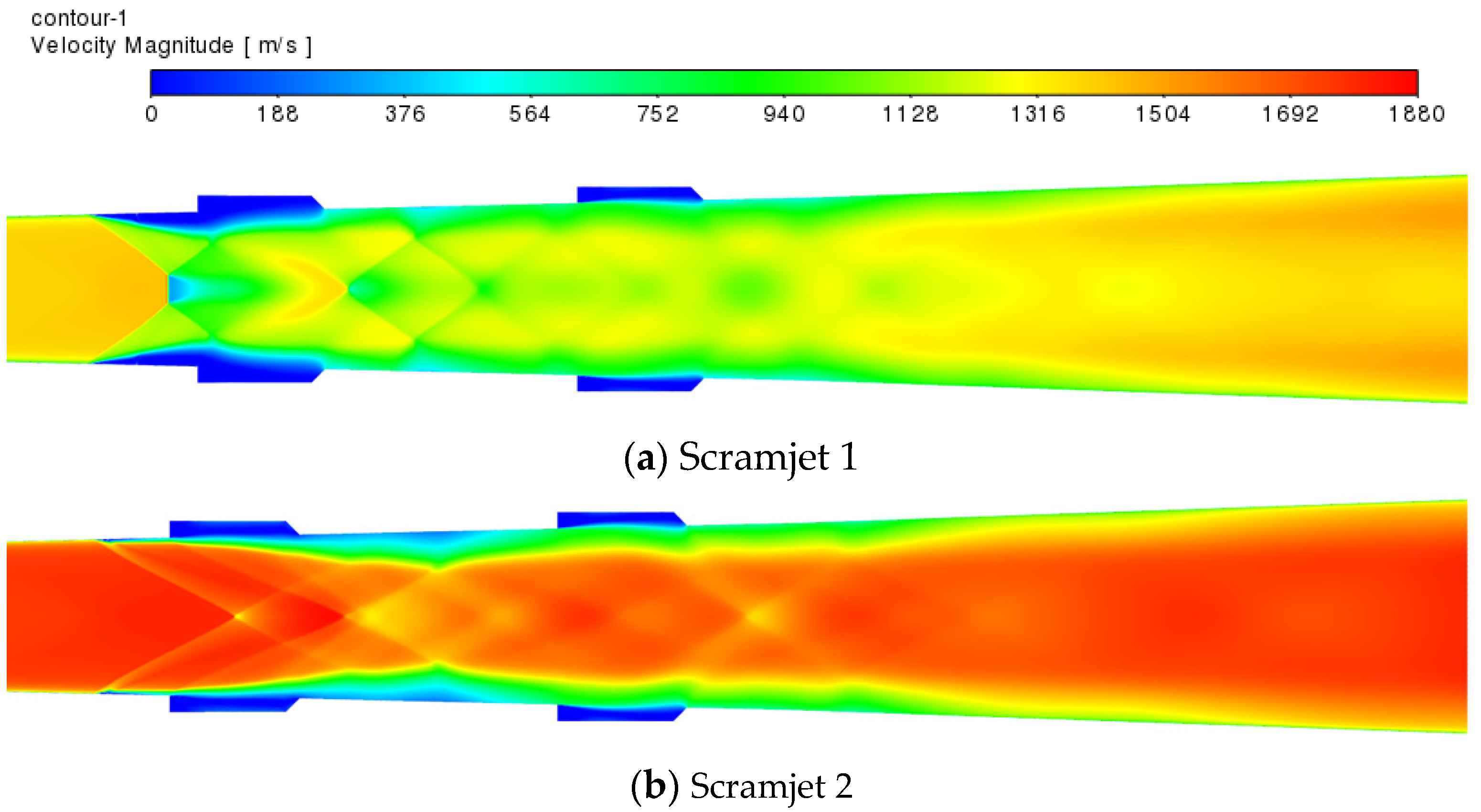
3.1. Combustion Flow Characteristics of the Scramjet

To study the combustion flow characteristics of the scramjet under Ma 6 and Ma 7 conditions, the commercial software Fluent is used to simulate the scramjet, and the temperature contours, pressure contours, and velocity contours of scramjet 1 and scramjet 2 are shown in Figure 6, Figure 7 and Figure 8.
The scramjet flow field exhibits the characteristics of a high flow velocity, limited combustion space, and complex shockwave system. When the Mach number increases from 6 to 7, the flow velocity at the combustor inlet increases accordingly, which not only shortens the residence time of the flow in the combustor, but also causes the separation point of the inlet airflow to move downstream, resulting in the first oblique shock wave at the inlet of the combustor moving downstream.
Based on the temperature contours, the flow field is roughly divided into three zones: an undisturbed zone, a mainstream zone, and a near wall combustion zone. The undisturbed zone is situated before the first oblique shock wave at the combustor entrance. The mainstream zone is situated in the central region after the first oblique shock wave. The near wall combustion zone is the region with high temperature between the main flow zone and the wall surface. The static temperature from high to low is near the wall combustion zone, mainstream zone, and undisturbed zone. Both scramjet 1 and scramjet 2 conditions indicate that the static temperature of the rear cavity is higher than that of the front cavity, indicating that the region around the rear cavity is more fully burned and more heat is released from this area.
At the outlet, there is little difference between the pressures of scramjet 1 and scramjet 2. In scramjet 1, because the angle between the shock and flow direction is larger, the compression effect of the flow behind the shock is more obvious, resulting in higher pressure. The high-pressure region under both operating conditions is mainly confined to the middle region of the combustor. The pressure difference between scramjet 1 and scramjet 2 is caused by the different angles of the oblique shock wave. A comparison of the velocity magnitude contours of scramjet 1 and scramjet 2 shows that the two have similar characteristics, but the mainstream of the scramjet 2 has a higher flow velocity.
Using the A-A section (Figure 2a) as the starting point, the species mass fraction of scramjet 1 and scramjet 2 is obtained, as shown in Figure 9. The mass fractions of each species for scramjet 1 and scramjet 2 are almost identical at the outlet position, signifying that the combustion efficiencies of scramjet 1 and scramjet 2 are basically identical. The CO mass fraction curve first rapidly increases, then slowly increases, and finally stabilizes, whereas the O2 mass fraction curve first rapidly decreases, then slowly decreases, and finally stabilizes. This shows that, with increasing axial distance, the rate of increase of combustion efficiency decreases.
In summary, for scramjet, when the Mach number of combustor inlet increases from 2.4 to 2.8, the position and shape of the first oblique shock wave will be significantly changed. That is, the oblique shock moves downstream, and the angle between the oblique shock and the flow velocity becomes smaller. The compression effect of air flow after shock wave is weak and the pressure after shock wave is reduced. However, the mass percentage of species under the two operating conditions is basically the same, indicating that there is little combustion efficiency difference between the two.

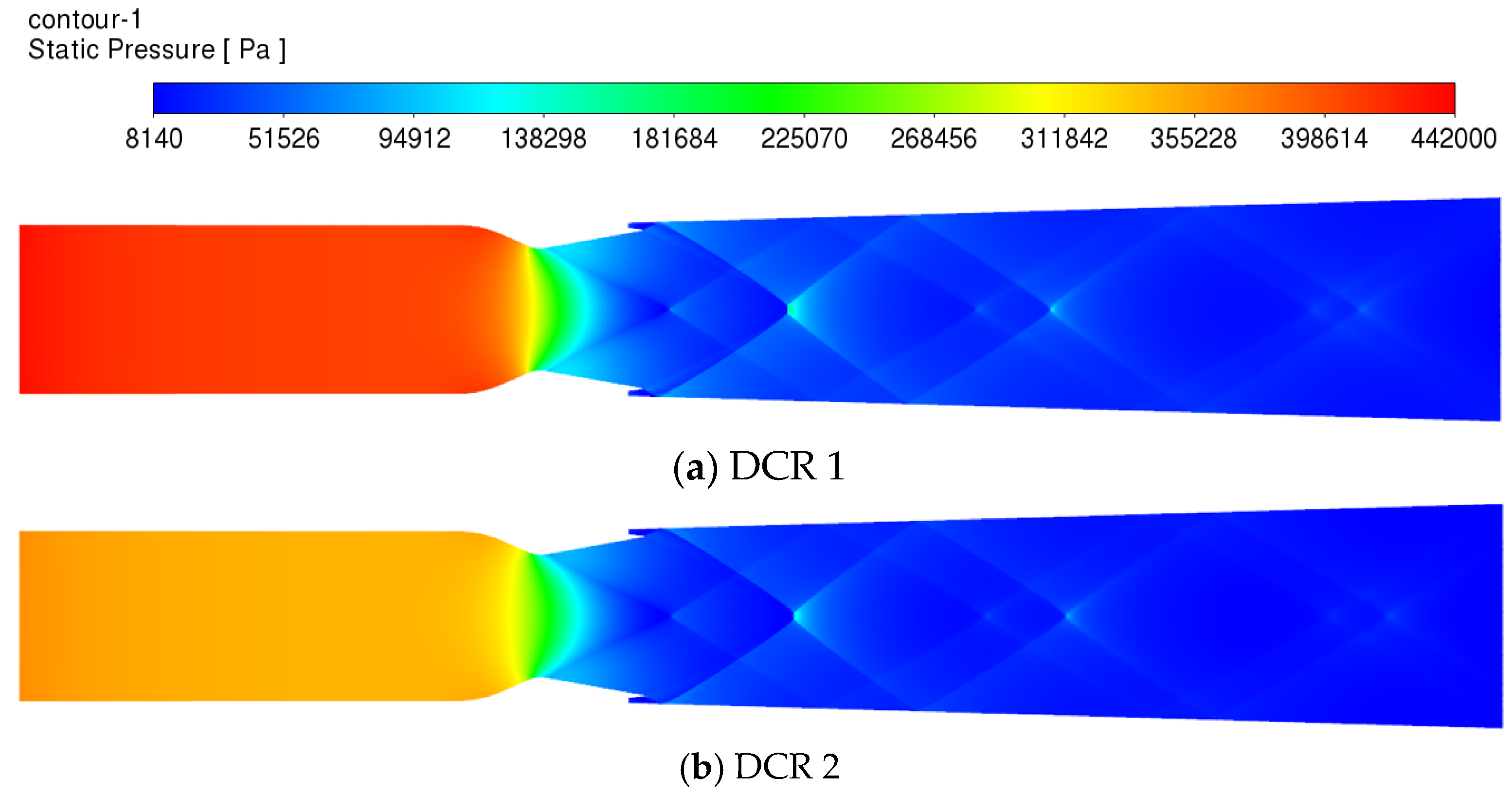
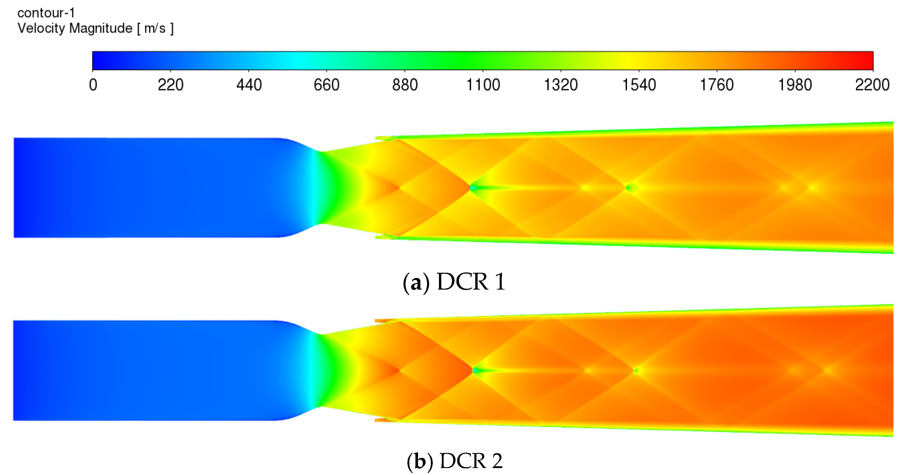
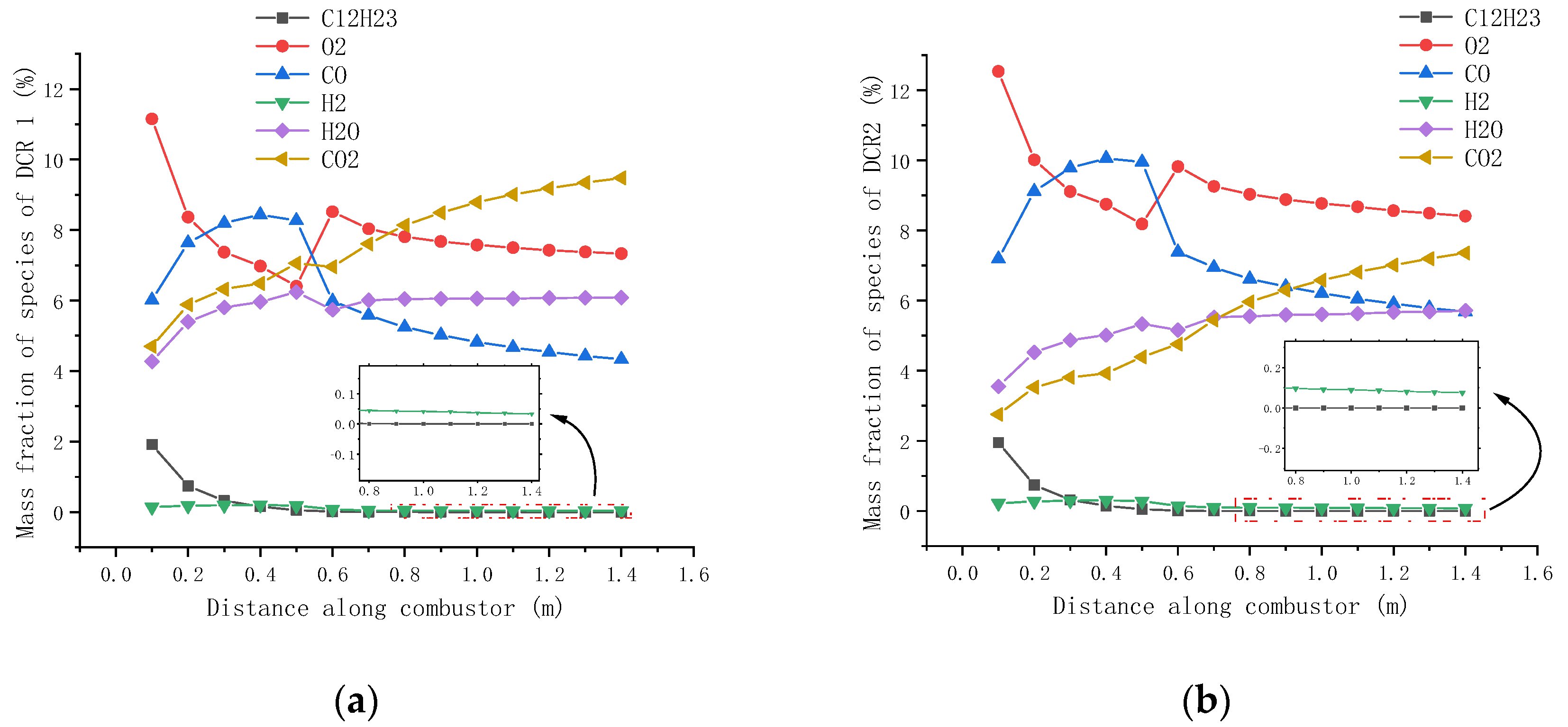
3.2. Combustion Flow Characteristics of DCR

Figure 10, Figure 11 and Figure 12 display the temperature contours, pressure contours, and velocity contours for DCR 1 and DCR 2. The largest difference between the contours of the scramjets and DCRs is in the combustion mode. That is, the scramjet is in near wall combustion mode, while the DCR is in central combustion mode. Moreover, the temperature gradient, pressure gradient, and velocity gradient of DCRs are smaller than those of the scramjets. This shows that, in the combustion mode of DCR, the heat release is relatively uniform.
For DCR 1 and DCR 2, in the subsonic combustor, the flow velocities are basically identical, but their temperatures and pressures vary. For DCR 2, the temperature is higher and the pressure is lower compared to DCR 1. The higher temperature stems from the higher total temperature of the free flow, and the lower pressure stems from the excessive total pressure loss when the free flow reaches the subsonic velocity. In the supersonic combustor, the temperature contours, pressure contours, and velocity contours of DCR 1 and DCR 2 exhibit similar characteristics. As the flow moves to the outlet, the temperature difference between DCR 1 and DCR 2 gradually decreases. This is because when the temperature increases, the chemical reaction equilibrium shifts toward that of an endothermic reaction, resulting in an increase in the degree of dissociation of CO2.
For DCR 1, the static pressures at the inlet and throat of the subsonic combustor are 400 and 330 kPa, respectively; for DCR 2, they are 370 and 270 kPa, respectively. In the supersonic combustor, the static pressure difference between DCR 1 and DCR 2 gradually decreases as the flow gradually flows to the outlet. In the supersonic combustor, the velocity in the central zone of the DCRs is higher than that in the near wall zone. The velocity distribution of DCR is more uniform than that of the scramjet, and its velocity is higher.
The species mass fractions for DCR 1 and DCR 2 are shown in Figure 13a,b, respectively. When the Mach number increased, the mass fraction of CO2 and H2O decreased, while the mass fraction of CO and O2 increased. Both the reduction and increase in DCR are greater than that of scramjet, indicating that the combustion efficiency of DCR decreases more after the Mach number increases. Notably, when the DCR is at position x = 0.5–0.6 m, under both sets of operating conditions, the mass fractions of O2 and CO significantly increase and decrease, respectively. This is because the inlet of the DCR supersonic chamber is located at x = 0.59 m. When the gas enters the supersonic chamber, the mass fraction of O2 increases sharply after being supplemented. On the one hand, the concentration of CO was diluted; on the other hand, the rate of CO reaction to produce CO2 was accelerated, and the combined effect of the two made the mass percentage of CO decrease sharply.
In summary, compared to the scramjet, the DCR has higher combustion efficiency and more uniform heat release. As a result, the DCR has a smaller gradient of temperature, pressure, and velocity than the scramjet. When the Mach number increases, the degree of CO2 dissociation of DCR increases due to increased static temperature, resulting in a more obvious decrease in combustion efficiency.

3.3. Comparison of Overall Performances of the Scramjet and DCR

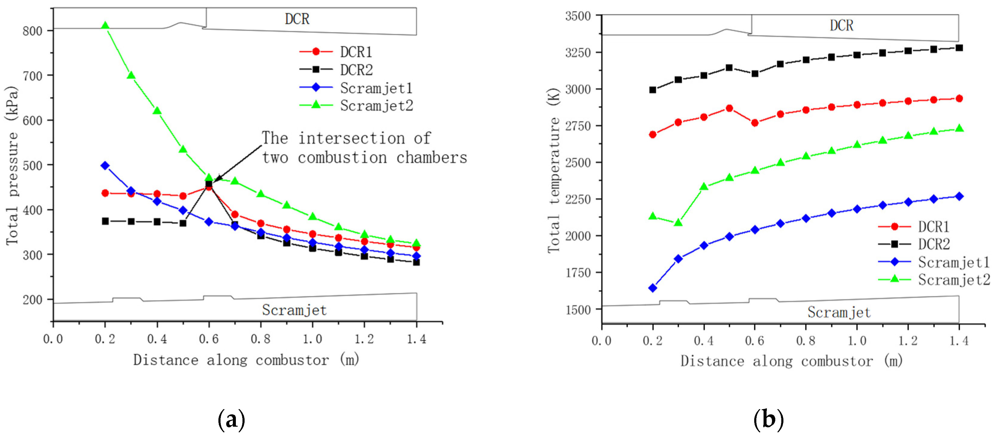
3.3.1. Comparison of Total Pressures, Total Temperatures, and Combustion Efficiencies

Figure 14a shows the total pressure variation curves of scramjet and DCR. At the inlet of the combustor, the total pressure of DCR is significantly lower than that of the scramjet. At the outlet, the total pressure of DCR is 19 kPa higher than that of scramjet under Ma 6, but 42 kPa lower under Ma 7. The total pressure of DCR at x = 0.6 m exhibits a sudden jump, which is caused by the convergence of the supersonic and mainstream gas flows. Although the inlet total pressure of the DCR subsonic combustor is low, the Rayleigh total pressure loss is also relatively low; thus, the total pressure of the subsonic combustor remains almost constant. For example, When Ma = 6, at position x = 0.3 m, the DCR total pressure exceeds the total pressure of scramjet. When Ma = 7, although the total pressure of DCR is always lower than that of the scramjet, the gap between the two decreases as the air gradually flows to the outlet. When Ma = 6, the total pressure recovery coefficient of DCR is higher than that of scramjet. In contrast, when Ma = 7, the total pressure recovery coefficient of scramjet is higher than that of DCR. This shows that when the Mach number increases, the total pressure recovery capability of scramjet is superior to that of DCR.
Figure 14b shows the total temperature variation curves of scramjet and DCR. It shows that the DCR total temperature slightly fluctuates at x = 0.6 m due to the convergence of the supersonic and mainstream gas flows. The total temperature of the scramjet increases with the axial distance, but the increase gradually slows down, indicating that the chemical reaction rate decreases with increasing axial distance. When the Mach number is increased from 6 to 7, the total temperature of DCR increases from 2934 to 3279 K and that of the scramjet increases from 2268 to 2727 K, which are increases of 12% and 20% for DCR and scramjet, respectively. Thus, when the Mach number increases, the total temperature rise of the scramjet is higher than that of DCR.
Figure 15a shows the combustion efficiency variation curves of DCR and scramjet. It shows that the variation curves of combustion efficiency are similar to that of total temperature for the same type of engine under the same operating condition. This is because when the heat transfer with the wall is ignored, the total temperature increases with increasing combustion efficiency. As the Mach number increases from 6 to 7, the scramjet combustion efficiency remains roughly the same, while the DCR combustion efficiency decreases from 80% to 70%. In other words, the DCR combustion efficiency is easier to decrease when the Mach number is increased.

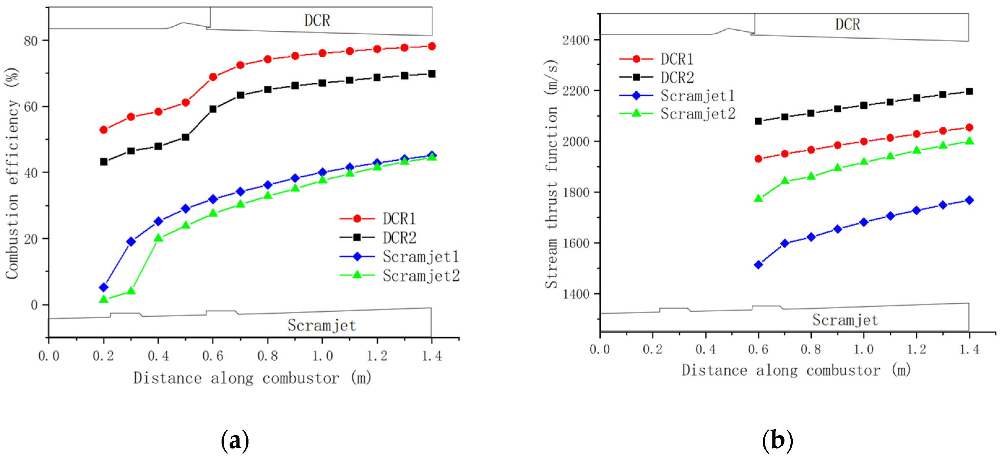
3.3.2. Comparison of Stream Thrust Functions

Equation (24) shows that the stream thrust function is a function of the axial velocity and temperature. Due to the interaction between fuel injection, mixing, combustion, and complex shock waves in the initial combustion stage of scramjet, the average flow velocity and temperature gradient change dramatically, and may even show oscillation phenomena. In order to eliminate the effect of this phenomenon on the stream thrust function, a comparative study has been conducted since x = 0.6, as shown in Figure 15b. At the outlet, when the Mach number increases from 6 to 7, the stream thrust function of both DCR and scramjet increases. DCR increased from 2054 m/s to 2194 m/s with an increase of 6.8%; Scramjet engine increased from 1768 m/s to 1999 m/s with an increase of 13%. Compared to scramjet, the DCR stream thrust function is 16% and 10% higher under Ma6 and Ma7 conditions, respectively. It shown that when the Mach number increases, the advantage of the DCR stream thrust function is weakened.

3.3.3. Comparison of the Overall Performances

To compare the overall performance of DCR and scramjet engines, the combustion efficiency, total pressure recovery coefficient, thrust, specific thrust, and specific impulse at the outlet are summarized as evaluation parameters, as shown in Table 3. The combustion efficiency of DCR 1 is 35.6% higher than that of scramjet 1, and the combustion efficiency of DCR 2 is 25.4% higher than that of scramjet 2. This indicates that the enhanced combustion advantage of DCR decreases with the increase in the Mach number. When the Mach number increases from 6 to 7, the combustion efficiency of DCR decreases because the static temperature increases greatly after the free flow stagnates to the subsonic velocity, and the static temperature will further increase to more than 3200 K due to chemical reaction exothermic heat. With increasing temperature, the dissociation rate of CO2 into CO increases, which ultimately leads to a decrease in combustion efficiency.
The total pressure recovery coefficient of scramjet is 0.9% lower than that of DCR under the Ma6 condition, but 5.6% higher than that of DCR under the Ma7 condition. Therefore, as the Mach number increases, the total pressure recovery performance of the scramjet is higher than that of DCR.
In terms of specific impulse, under Ma6 and Ma7 conditions, the specific impulse of DCR is 2.67 and 1.51 times that of scramjet, respectively, indicating that the performance of DCR is better than that of scramjet under these two conditions. However, with the increase of Mach number, this advantage gradually decreases. The reason is that with the increasing Mach number, the specific impulse of scramjet increases slightly, but the specific impulse of DCR decreases by 30%. The specific thrust is similar and will not be repeated.
Compared to scramjet, the subsonic combustor of DCR provides a low-speed, high-temperature, and high-pressure environment, which is not only conducive to uniform fuel mixing, but also can promote ignition and improve combustion efficiency, and ultimately improve the overall performance of the engine.

4. Conclusions

To provide theoretical guidance for the engine selection of a hypersonic vehicle, the overall performance of DCR and scramjet engine was compared via computational fluid dynamics numerical simulation technology. The scramjet had a single-stage injection and double cavity structure. The length of the DCR was consistent with the scramjet combustor but without the double cavity structure. Kerosene, C12H23, with an equivalence ratio of 0.8, was employed as the fuel, and the reactive flow was modeled using six-species and four-step chemistry. Flight Mach numbers Ma 6 and Ma 7 and an altitude of 30 km were selected as the operating conditions for comparison. The conclusions of the study are as follows.
(1)
The two types of engines had different combustion modes. The scramjet was a near wall combustion mode, while the DCR was a central combustion mode, which had small pressure fluctuation, small temperature gradient, good heat release uniformity, and high combustion stability.
(2)
When the Mach number increased, the total pressure recovery capability of scramjet was superior to that of DCR. Specifically, the total pressure recovery coefficient of scramjet was 0.9% lower than that of DCR under the Ma6 condition, but 5.6% higher than that of DCR under the Ma7 condition.
(3)
The combustion efficiency of DCR was 35.6% and 25.4% higher than that of scramjet under Ma6 and Ma7 conditions, respectively. When the Mach number increased from 6 to 7, the combustion efficiency of the scramjet remained almost unchanged, and that of DCR decreased by 10%. This was because the dissociation rate of CO2 into CO increased with increasing temperature.
(4)
The performance of DCR was better than that of scramjet under both conditions. However, the performance advantage of DCR decreased as the Mach number increased. Specifically, under the conditions of Ma6 and Ma7, the specific impulse or specific thrust of DCR was 2.67 times and 1.51 times of scramjet, respectively.

Author Contributions

Conceptualization, Z.W.; methodology, Z.W.; software, X.W.; validation, X.W.; formal analysis, X.W.; investigation, X.W.; resources, Z.W.; data curation, X.W.; writing—original draft preparation, X.W.; writing—review and editing, Z.W.; visualization, X.W.; supervision, Z.W.; project administration, X.W.; funding acquisition, Z.W. All authors have read and agreed to the published version of the manuscript.

Funding

This study was supported by the National Natural Science Foundation of China (No. U21B2086) and the Taizhou Science and Technology Bureau of China (No. 2002gy07).

Institutional Review Board Statement

Not applicable.

Informed Consent Statement

Not applicable.

Data Availability Statement

Not applicable.

Acknowledgments

Thanks to my father and mother, who are ordinary Chinese farmers and worked hard to pay for my education. I finally became a university teacher after going through many difficulties. This paper is dedicated to my deceased mother, may her spirit rest in heaven. In addition, my wife has given me great support during my study.

Conflicts of Interest

The authors declare no conflict of interest.

Nomenclature

m ˙ Mass of flow per unit time, kg/s.
MMolar mass, kg/mol.
h ¯ f 0 Formation enthalpy, J/mol.
TTemperature, K.
PPressure, kPa.
MaMach number.
η c Combustion efficiency.
KpTotal pressure recovery coefficient.
FThrust, which is the thrust gain in the paper, N.
ISpecific impulse, m/s.
S P Specific thrust, m/s.
S a Stream thrust function, m/s.
u Axial velocity of air flow, m/s.
R The average gas constant of the flow, J/(kg·k).
h b u r n Heat released per unit mass of complete combustion, J/kg.
Subscripts
A_totSum of the air mass of the subsonic combustor and supersonic combustor.
fuelFuel, i.e., kerosene.
hotOperating conditions when the fuel is burned.
coldOperating conditions when the fuel is not burned.
netNet increase value.
c_inInlet of combustor.
0The state of a stagnant air flow.
1Operating condition 1, which is 30 km flight altitude and Mach 6.
2Operating condition 2, which is 30 km flight altitude and Mach 7.

References

  1. Sziroczak, D.; Smith, H. A review of design issues specific to hypersonic flight vehicles. Prog. Aeosp. Sci. 2016, 84, 1–28. [Google Scholar] [CrossRef] [Green Version]
  2. Urzay, J. Supersonic Combustion in Air-Breathing Propulsion Systems for Hypersonic Flight. Annu. Rev. Fluid Mech. 2018, 50, 593–627. [Google Scholar] [CrossRef]
  3. Liu, Q.; Baccarella, D.; Lee, T. Review of combustion stabilization for hypersonic airbreathing propulsion. Prog. Aeosp. Sci. 2020, 119, 100636. [Google Scholar] [CrossRef]
  4. Billig, F.S.; Waltrup, P.J.; Stockbridge, R.D. Integral-Rocket Dual-Combustion Ramjets: A New Propulsion Concept. J. Spacecr. Rockets 1980, 17, 416–424. [Google Scholar] [CrossRef]
  5. Waltrup, P.J. The dual combustor ramjet: A versatile propulsion system for hypersonic tactical missile applications. In AGARD, Airbreathing Propulsion for Missiles and Projectiles 11 p (SEE N93-17607 05-20); AGARD: Villepreux, France, 1992. [Google Scholar]
  6. Tan, J.; Wang, Y. Freejet Experimental Investigation on Performance of Dual-Combustion Ramjet. J. Propul. Power 2015, 31, 478–482. [Google Scholar] [CrossRef]
  7. Segal, C. The Scramjet Engine: Processes and Characteristics; Cambridge University Press: Cambridge, NY, USA, 2009. [Google Scholar]
  8. Choubey, G.; Devarajan, Y.; Huang, W.; Mehar, K.; Tiwari, M.; Pandey, K.M. Recent advances in cavity-based scramjet engine- a brief review. Int. J. Hydrogen Energy 2019, 44, 13895–13909. [Google Scholar] [CrossRef]
  9. Chang, J.; Zhang, J.; Bao, W.; Yu, D. Research progress on strut-equipped supersonic combustors for scramjet application. Prog. Aeosp. Sci. 2018, 103, 1–30. [Google Scholar] [CrossRef]
  10. Gerdroodbary, M.B. Injection and Mixing of Single Fuel Jet in SCRAMJET Engine; Butterworth-Heinemann: Kidlington, UK, 2020. [Google Scholar]
  11. Wadwankar, N.; Kandasamy, G.; Ananthkrishnan, N.; Renganathan, V.S.; Park, I.; Hwang, K. Dual combustor ramjet engine dynamics modeling and simulation for design analysis. Proc. Inst. Mech. Eng. Part G J. Aerosp. Eng. 2019, 233, 1307–1322. [Google Scholar] [CrossRef]
  12. Jiang, Y.; Abu-Hamdeh, N.H.; Bantan, R.A.R.; Moradi, R. Mixing efficiency of hydrogen and air co-flow jets via wedge shock generator in dual-combustor ramjet. Aerosp. Sci. Technol. 2021, 116, 106846. [Google Scholar] [CrossRef]
  13. Fry, R.S. A Century of Ramjet Propulsion Technology Evolution. J. Propul. Power 2004, 20, 27–58. [Google Scholar] [CrossRef]
  14. Yang, Z.; Shan, P.; Guo, D.; Zhao, L.; Jie, K.; Liu, J. Design Improvement and Validation of Subsonic Combustor Pilot Burner for Dual Combustor Ramjet. J. Propuls. Technol. 2013, 34, 69–75. [Google Scholar]
  15. Zhang, L.; Sung, H.; Yang, V. Flow and Flame Dynamics in a Hydrocarbon-fueled Dual-Combustion Ramjet Engine; AIAA SciTech Forum: Orlando, FL, USA, 2020. [Google Scholar]
  16. Stockbridge, R.D.; Schetz, J.A.; Waltrup, P.J.; Billig, F.S. Combustor/Inlet Interactions and Modeling of Hypersonic Dual Combustor Ramjet Engines; Air Force Office of Scientific Research: Washington, WA, USA, 1984. [Google Scholar]
  17. Stockbridge, R.D. Experimental investigation of shock wave/boundary-layer interactionsin an annular duct. J. Propul. Power 1989, 5, 346–352. [Google Scholar] [CrossRef]
  18. Raghavendra Rao, M.; Amba Prasad Rao, G.; Charyulu, B.V.N.; Singh, H. Numerical studies and validation of combustor and annular isolator interactions of hydrocarbon based axisymmetric dual combustion ramjet. Aerosp. Sci. Technol. 2020, 106, 106185. [Google Scholar] [CrossRef]
  19. Situ, M.; Wang, C.; Lu, H. Investigation on supersonic combustion of fuel-rich hot gas as reacting jets in ramjet scramjet combustor. J. Propuls. Technol. 2001, 22, 237–240. [Google Scholar]
  20. Vaught, C.; Witt, M.; Netzer, D.; Gany, A. Investigation of solid-fuel, dual-mode combustion ramjets. J. Propul. Power 1992, 8, 1004–1011. [Google Scholar] [CrossRef]
  21. Raghavendra Rao, M.; Amba Prasad Rao, G.; Kumar, A. Experimental validation of liquid hydrocarbon based fuel rich gas generator for high speed propulsion systems. Acta Astronaut. 2020, 174, 180–188. [Google Scholar] [CrossRef]
  22. Tan, J.; Wu, J.; Wang, Z. Experimental and numerical investigations on flow fields and performance of dual combustion ramjet. Proc. Inst. Mech. Eng. Part G J. Aerosp. Eng. 2014, 228, 920–929. [Google Scholar] [CrossRef]
  23. Menter, F.R. Two-equation eddy-viscosity turbulence models for engineering applications. AIAA J. 1994, 32, 1598–1605. [Google Scholar] [CrossRef] [Green Version]
  24. Cai, G.; Li, C.; Tian, H. Numerical and experimental analysis of heat transfer in injector plate of hydrogen peroxide hybrid rocket motor. Acta Astronaut. 2016, 128, 286–294. [Google Scholar] [CrossRef]
  25. Yan, D.; He, G.; Qin, F.; Zhang, D.; Shi, L. Effect of the heat release on the component coordination in the rocket-based combined cycle engine. Acta Astronaut. 2018, 151, 942–952. [Google Scholar] [CrossRef]
  26. Hjertager, L.K.; Hjertager, B.H.; Solberg, T. CFD modelling of fast chemical reactions in turbulent liquid flows. Comput. Chem. Eng. 2002, 26, 507–515. [Google Scholar] [CrossRef]
  27. Jones, W.P.; Lindstedt, R.P. Global reaction schemes for hydrocarbon combustion. Combust. Flame 1988, 73, 233–249. [Google Scholar] [CrossRef]
  28. Yao, W.; Yuan, Y.; Li, X.; Wang, J.; Wu, K.; Fan, X. Comparative Study of Elliptic and Round Scramjet Combustors Fueled by RP-3. J. Propul. Power 2018, 34, 772–786. [Google Scholar] [CrossRef]
  29. Bonfiglioli, A.; Paciorri, R. Convergence Analysis of Shock-Capturing and Shock-Fitting Solutions on Unstructured Grids. AIAA J. 2014, 52, 1404–1416. [Google Scholar] [CrossRef]
  30. Byun, J.; Park, C.; Kwon, O.J.; Ahn, J. Experimental Study of Combustor-Isolator Interactions in a Dual-Combustion Ramjet. J. Propul. Power 2015, 31, 592–603. [Google Scholar] [CrossRef]
  31. Heiser, W.H. Hypersonic Airbreathing Propulsion; American Institute of Aeronautics and Astronautics: Washington, DC, USA, 1994. [Google Scholar]
  32. Liu, Y.; Gao, Y.; Chai, Z.; Dong, Z.; Hu, C.; Yu, X. Mixing and heat release characteristics in the combustor of solid-fuel rocket scramjet based on DES. Aerosp. Sci. Technol. 2019, 94, 105391. [Google Scholar] [CrossRef]
  33. Wu, K.; Zhang, P.; Fan, X. On jet-wake flame stabilization in scramjet: A LES/RANS study from chemical kinetic and fluid-dynamical perspectives. Aerosp. Sci. Technol. 2022, 120, 107255. [Google Scholar] [CrossRef]
Figure 1. Operating Mach number range for different types of engines.
Applsci 13 00480 g001
Figure 2. Geometric model of (a) the scramjet [28] and (b) the DCR (unit: mm).
Applsci 13 00480 g002
Figure 3. (a) Grid convergence behavior and (b) wall pressure with axial distance.
Applsci 13 00480 g003
Figure 4. Comparison curves of wall pressure under the conditions of equivalence ratio of (a) 0 and (b) 0.71.
Applsci 13 00480 g004
Figure 5. Local mesh of (a) the scramjet and (b) the DCR.
Applsci 13 00480 g005
Figure 6. Static temperature contours for scramjet 1 and scramjet 2. 1—Undisturbed zone, 2—Mainstream zone, and 3—Near wall combustion zone.
Applsci 13 00480 g006
Figure 7. Static pressure contours for scramjet 1 and scramjet 2.
Applsci 13 00480 g007
Figure 8. Velocity magnitude contours for scramjet 1 and scramjet 2.
Applsci 13 00480 g008
Figure 9. Species mass fraction for (a) scramjet 1 and (b) scramjet 2.
Applsci 13 00480 g009
Figure 10. Static temperature contours for DCR 1 and DCR 2.
Applsci 13 00480 g010
Figure 11. Static pressure contours for DCR 1 and DCR 2.
Applsci 13 00480 g011
Figure 12. Velocity magnitude contours for DCR 1 and DCR 2.
Applsci 13 00480 g012
Figure 13. Species mass fraction for (a) DCR 1 and (b) DCR 2.
Applsci 13 00480 g013
Figure 14. Curves for (a) total pressure and (b) total temperature.
Applsci 13 00480 g014
Figure 15. Curves for (a) combustion efficiency and (b) stream thrust function.
Applsci 13 00480 g015
Table 1. Comparison of adiabatic flame temperature and ignition delay with literature.
Initial Temperature, KFlame TemperatureIgnition Delay
2185 Species, K Six-Species, K 2185 Species, s Six-Species, s
Condition 11600278027213 × 1052.6 × 107
Condition 22200294828983.5 × 1064.6 × 108
Table 2. Boundary conditions of DCRs and scramjets.
m ˙ A _ t o t kg/sT0, KP0, kPaMac_in
Scramjet 13.7216948892.4
Scramjet 22.74222412412.8
DCR 13.721694889 (448)2.4 (0.3)
DCR 23.0322241241 (383)2.8 (0.3)
Note: the inlet parameters of DCR subsonic combustor are given in the parentheses.
Table 3. Overall engine performance for DCR and scramjet.
ηcKpF, NSp, m/sI, m/s
Scramjet 144.40.37110192745009
Scramjet 244.60.2987992925338
DCR 1800.38271973113,364
DCR 2700.24213394428087
Disclaimer/Publisher’s Note: The statements, opinions and data contained in all publications are solely those of the individual author(s) and contributor(s) and not of MDPI and/or the editor(s). MDPI and/or the editor(s) disclaim responsibility for any injury to people or property resulting from any ideas, methods, instructions or products referred to in the content.

