Article

Structural Design and Optimization of Separated Air-Rib Tents Based on Response Surface Methodology

1
School of Mechanical-Electronic and Vehicle Engineering, Beijing University of Civil Engineering and Architecture, Beijing 100044, China
2
Beijing Engineering Research Center of Monitoring for Construction Safety, Beijing 100044, China
3
Institute of Defense Engineering, AMS, PLA, Beijing 100850, China
*
Authors to whom correspondence should be addressed.
Appl. Sci. 2023, 13(1), 55; https://doi.org/10.3390/app13010055
Submission received: 10 November 2022 / Revised: 12 December 2022 / Accepted: 13 December 2022 / Published: 21 December 2022

Abstract

:
Air-rib tents are widely used because they are lightweight and site adaptable, but the large deformation of these tents reduces their effective space. It is important to reduce the displacement of the air-rib tent by parameter optimization. The influences of external factors on the tent are studied in this paper. Four parameters of the tent’s wind ropes are the angle of the wind ropes, the number of the wind ropes, and the initial prestress of the wind ropes on the side or end faces. The influence of the angle of the wind ropes and the number of the wind ropes on the displacement is larger than the other two parameters. The closer the wind ropes are to the center of the tarpaulin, the greater the displacement of the tent. Based on an analysis using response surface methodology, the optimal parameters are as follows: the angle of the wind ropes is 41°, the number of the wind ropes on the side is two, the initial prestress of the wind ropes on the end face is 800 Pa, and the initial prestress of the wind ropes on the side is 0 Pa. Under these optimal parameters, the maximum displacement decreases by 10.2%, and the maximum stress barely changes.

1. Introduction

As simple and foldable building structures, inflatable tents are lightweight and site adaptable. Along with the development of generalization, integration, and facilitation [1,2], inflatable tents are widely used in tourism, military, disaster relief, and construction fields. Air-rib tents, which are one kind of inflatable tent, are widely used. These tents are supported by air ribs which are filled with high-pressure air and based on the shape of the ribs, and they include two main types: arched rib tents and broken-line rib tents. They can also be divided into vertical types and curved types by the arrangement of ribs, as shown in Figure 1.
Compared with a tent supported by a metal frame, the displacement of an air-rib tent under external load is larger [5,6]. The main evaluation indexes for the stability of an air-rib tent are stress and displacement. The bearing capacity of an arched-rib tent is better than that of a tent with broken-line ribs in the same arrangement. Tents with curved type ribs can resist more loads than tents with the vertical type [3]; however, a tent of the vertical type has more effective space. The large deformation of the tent reduces the effective space, so it is important to reduce the displacement of air-rib tents by parameter optimization.
To analyze the mechanical properties of structures, there are, mainly, test and finite element simulation methods. Because of the large size of separated air-rib tents, the testing cost is high. Using the finite element method, the calculation time is short, the applicability is strong, and the testing cost is low [7,8]. Therefore, finite element analysis is more suitable for tent mechanical property analysis. The influence of the structural parameters of an air-rib tent on its load bearing capacity has been studied by many scholars. Cui et al. [9] established a finite element model of a long-span skeleton membrane structure by tension-only bar elements. A prestressed cable was added to the membrane structure to meet the strength requirements. Wu et al. [10] set up cables to enhance the stability of a dry coal shed with a long span. The dry coal shed was composed of cable-arch trusses, and the prestressed cable was represented by a bar element in the simulation model. Li et al. [11] established a finite element model of an air-tight inflatable tent, and the rod element Link10 was used to simulate the wind ropes. The effects of parameters such as the internal pressure of the tent, the internal pressure of the ribs, and the structural parameters on the stability were studied. He et al. [12,13] explored the wind pressure distribution of a large stadium by wind tunnel tests and finite element simulation methods. They proposed that a cable can reduce the displacement of the membrane, and showed that the cross-sectional area of the cable has no significant effect on the displacement. To date, most researchers have improved the stability of structures by adding wind ropes, but less research has investigated the influence of wind rope parameters on the tarpaulin displacement. Therefore, it is necessary to optimize the structure of wind ropes by exploring the influence of wind rope parameters on the tent.
Currently, the main optimization methods are the response surface methodology [14,15,16,17], the linear weighting method [18], the coupled genetic algorithm [19], the chaotic water strider algorithm [20], and the primary objective method [21]. The response surface methodology transforms the implicit function relation in the actual model into a direct function relation by mathematical statistics; then, the optimal solution is determined [22,23]. The response surface methodology can reduce the number of experiments effectively, and obtain the relationships of influencing factors. Peng [24] established a finite element model of frame stope with different structural parameters, and optimized the pillar size based on the response surface methodology. Zhan et al. [25] obtained the relationship between the cable force and the maximum displacement (between the two ends of the crossbeam) by the response surface methodology. The particle swarm optimization algorithm was used to optimize the cable force. Zhu et al. [26] optimized the weight of composite perforated plate of ship by the response surface methodology and finite element simulation together.
In this paper, the wind and snow load are applied to the separated air-rib tents, the effects of the wind rope parameters on the Von Misses stress and displacement of the separated air-rib tents are explored by the control variable method, and the value range of each factor is determined. The response value equation, which reflects the relationship between the maximum displacement and wind rope parameters, is established by the response surface methodology, and the optimal values of the wind rope parameters are obtained.

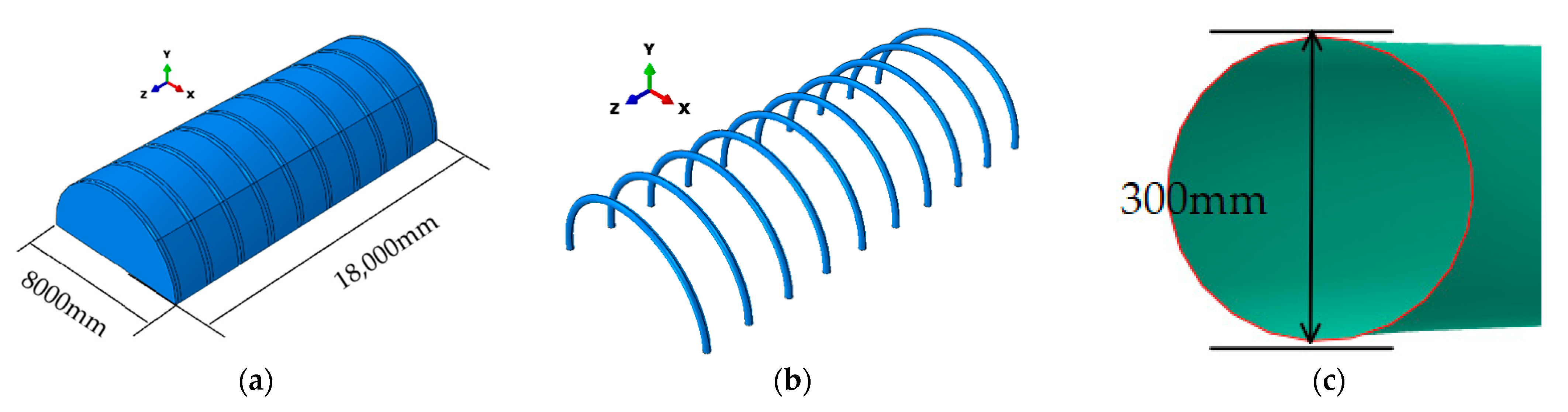
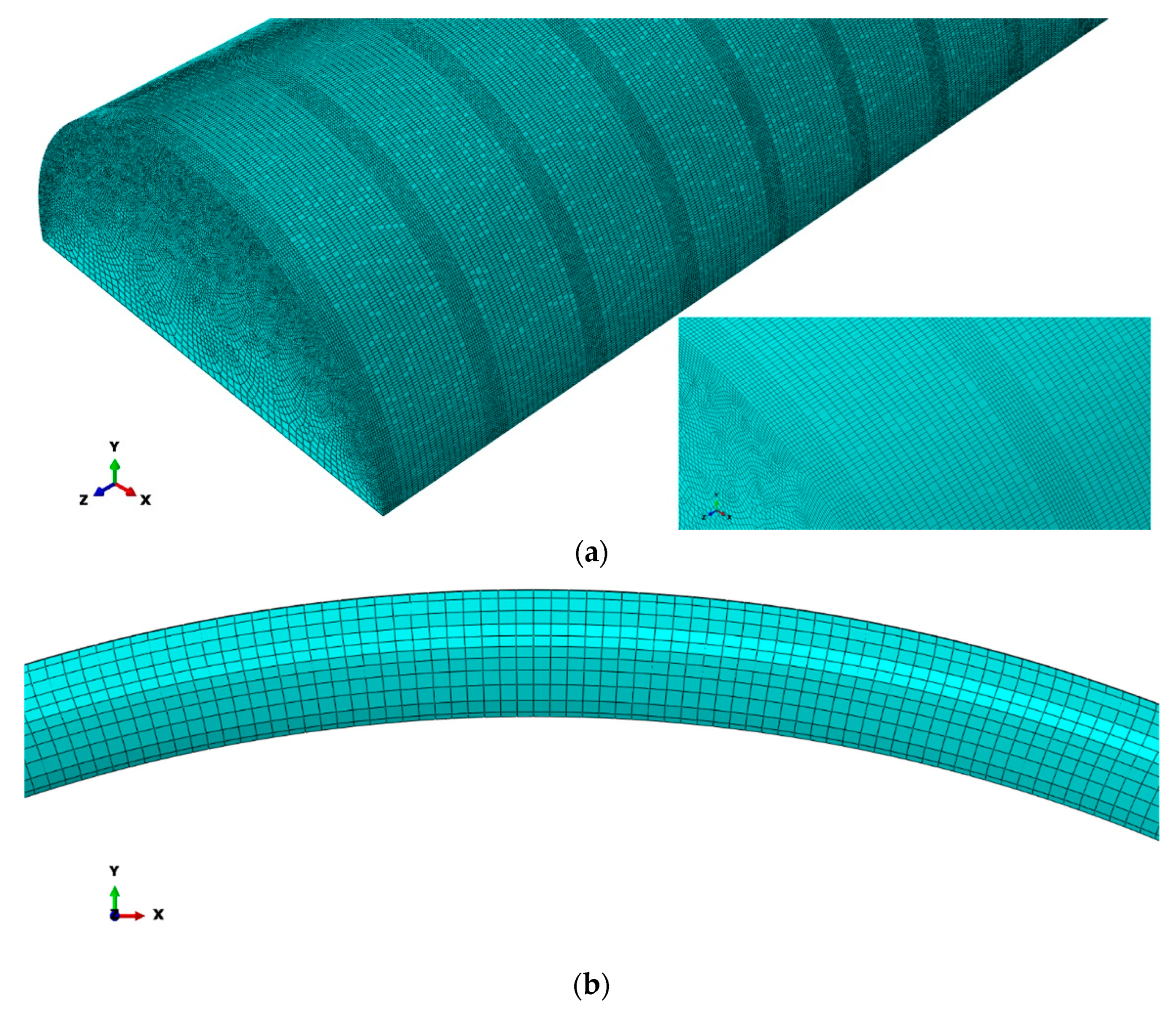
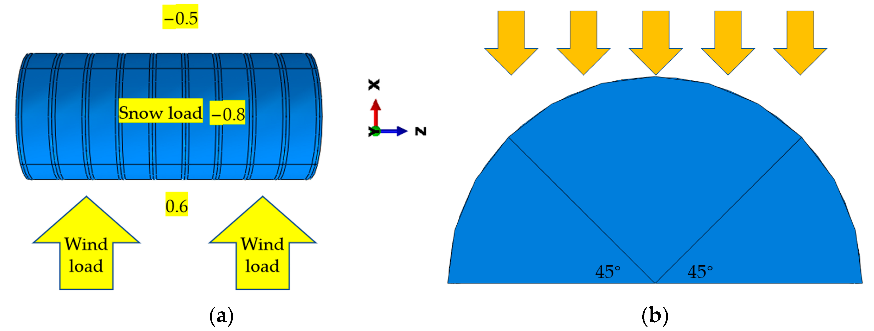
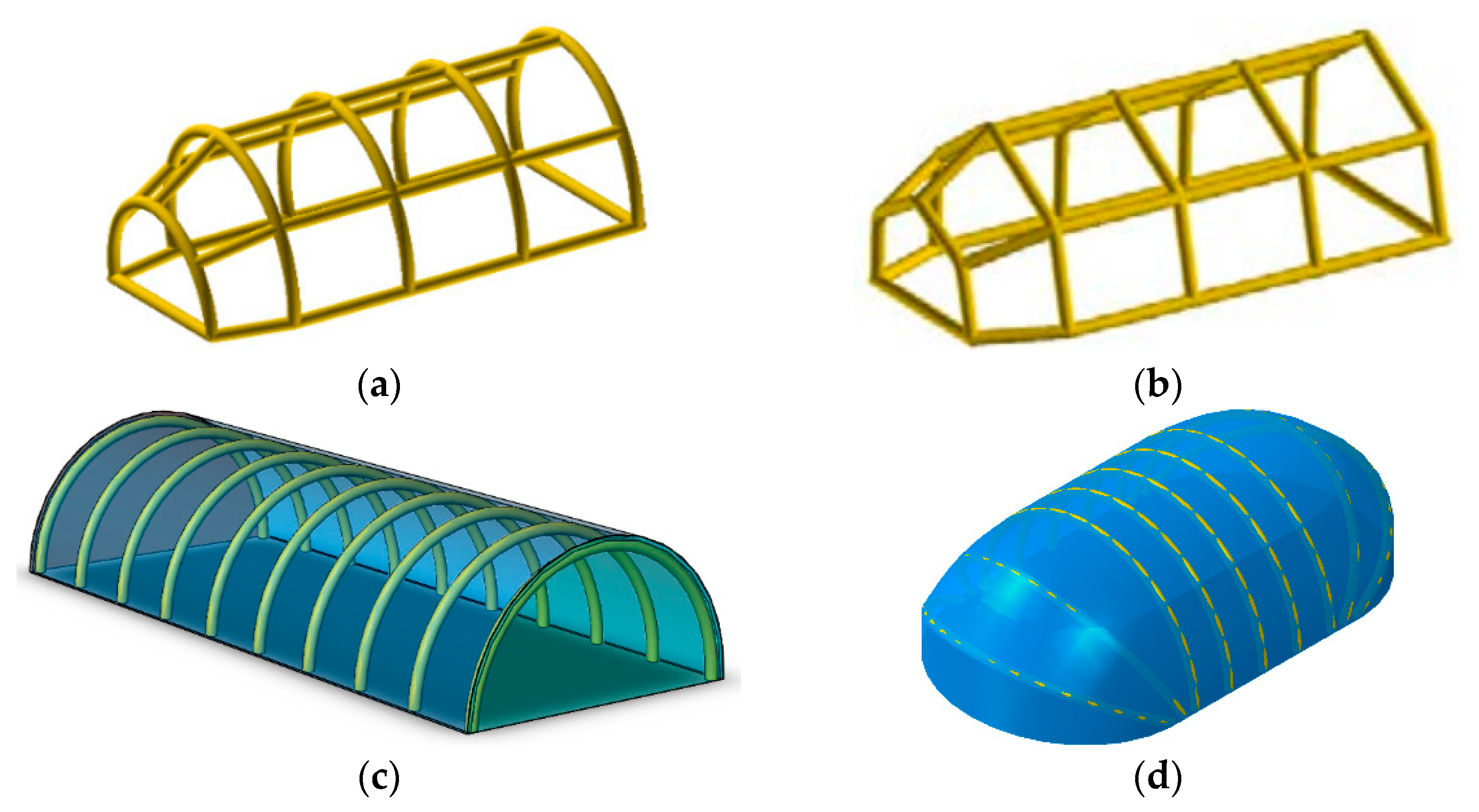
2. Numerical Calculation Model of Separate Air-Ribbed Tent

A numerical model of the separated air-rib tent is established by ABAQUS 6.14 (SIMULIA Company, Providence, RI, USA). The separated air-rib tent consists of separated arch ribs and a tarpaulin, which is shown in Figure 2. The structural dimension parameters are derived from the best-selling product of a tent supplier. The width of the tent is 4 m, and the length is 18 m. For the ribs, the cross-section diameter of a rib is 0.3 m, and the centerline radius of a rib is 4 m. The distance between two ribs is 2 m, and ten ribs are arranged side by side. The tarpaulin and air ribs are made of two new braided materials, and the property parameters of the two materials are shown in Table 1. The inflated air ribs are mainly used to support the tent, and the working pressure of the ribs is 0.2 MPa [9]. The wind ropes are added to strengthen the stability of the separated air-rib tent. The cross-section diameter of the wind ropes is 8.9 mm, and the elastic modulus is 2.82 GPa.
The tarpaulin and the air rib are set as membrane elements (M3D4R) [27], and the wind ropes are set as truss elements (T3D2) [28]. At the beginning of the simulation, the geometric is coarse meshed. To improve the calculation accuracy, the connection position between the tarpaulin and the air rib is divided into finely grid cells. The stress and the displacement change little with further refinement of the grid cells [29]. The grid cells are shown in Figure 3. The model has a total of 148,734 grid cells and 149,017 nodes. The tarpaulin has 69,002 grid cells and 69,025 nodes, and the air ribs have 75,360 grid cells and 75,600 nodes.
In the model, the edge of the tarpaulin and the air ribs are fixed to the ground to restrict the XYZ three direction axial movement and rotating movement. The tarpaulin is tangent to the air rib, and the contact area is narrow to be simplified into line contact. So, the node coordinates on the contact line of the tarpaulin and the air ribs are consistent [30]. One end of a wind rope is fixed to ground, and the other end is fixed to the tarpaulin by binding constraint, and then the initial prestress is added to the wind ropes [31].
According to the extreme condition of the Load Code for the Design of Building Structures (GB50009-2012), standard dead load, wind load, and snow load are applied to the tent. The standard dead load is the gravity, the value is 9.8 m/s2, and load coefficient is 1.3. The coefficients of wind load and snow load are both 1.5. Based on the force eight wind, the essential wind pressure is set to be 0.3 kN/m2, and the combined load coefficient is 0.6. The coefficient is shown in Figure 4, and wind pressure applied on the tent is calculated by the following Formula (1):
w k = β z μ s μ z w 0
In the formula, wk is the standard value of wind load (kN/m2), βz is the wind vibration coefficient at height z, μs is the wind load figure coefficient, μz is the coefficient of variation of wind pressure height, taken as 1.0; w0 is the basic wind pressure (kN/m2).
The pressure of the return period of 100 years in North China is defined as average basic snow, namely 0.5 kN/m2. As shown in Figure 4, the snow load is applied on the top of the tent, and it can be calculated as follows (2):
S k = μ r S 0
In the formula, Sk is the standard snow load value (kN/m2), μr is the roof snow distribution coefficient, and S0 is the basic snow pressure (kN/m2).

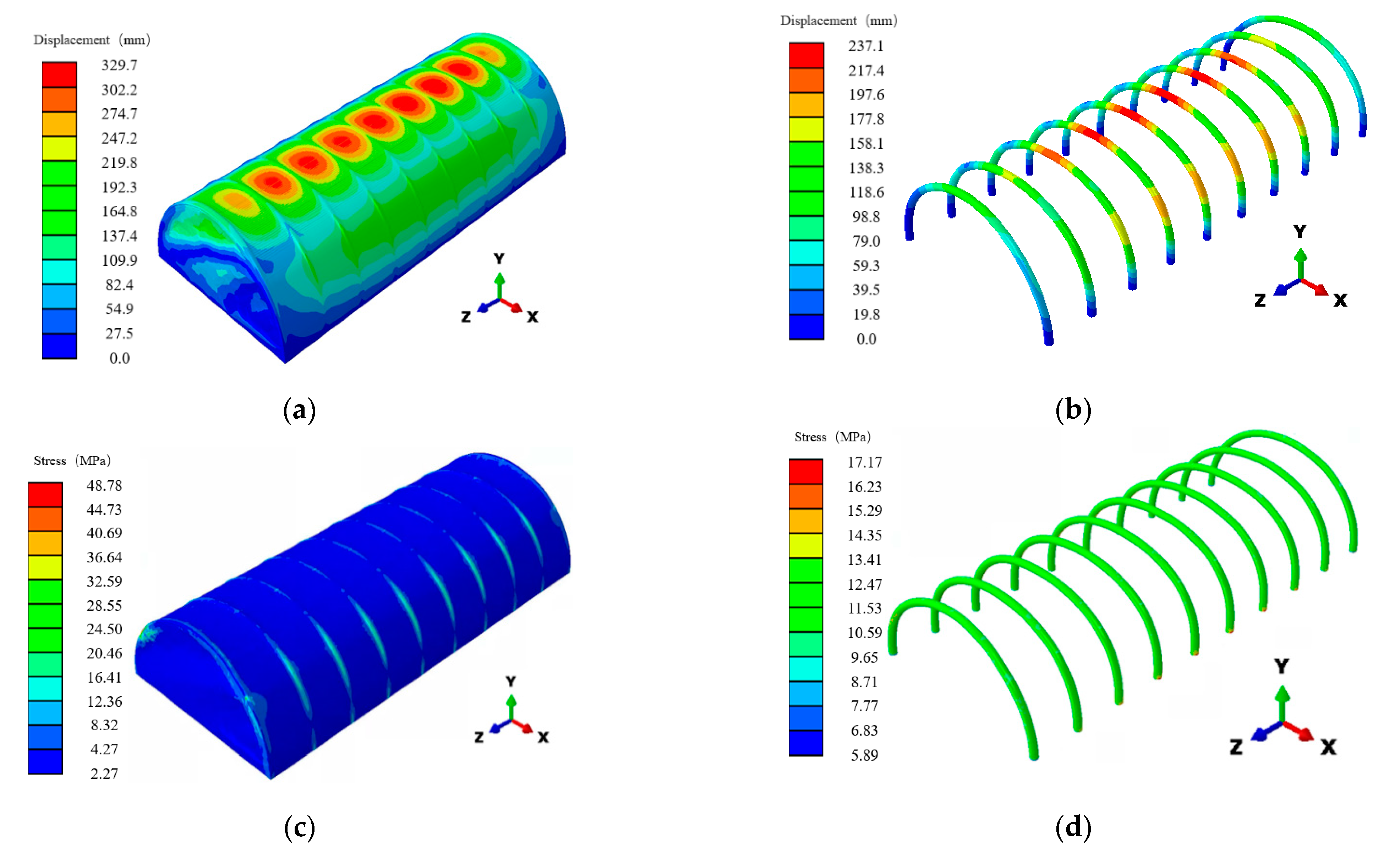
3. A Single Parameter Analysis of Separated Air-Rib Tent

In the simulation of the separated air-rib tent, the angle of the wind ropes, the number of the wind ropes on the side, and the initial prestress of the wind ropes on the end face and the side, are four critical external parameters to be studied. The process flowchart of the proposed methodology is shown in Figure 5. The test scheme by the control variable method is shown in Table 2. The influence of each parameter on the Von Misses stress and displacement of the tent is analyzed.

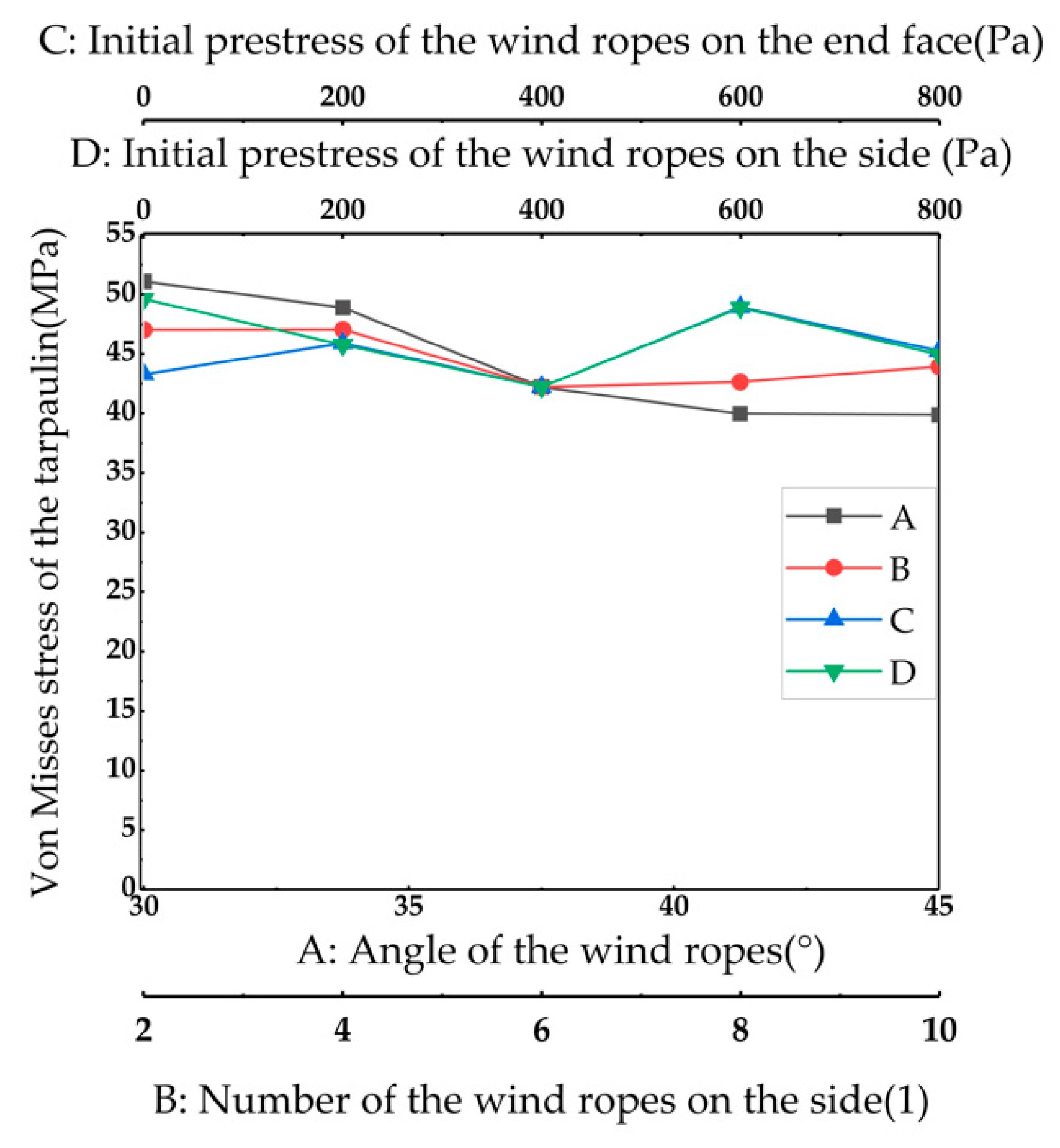
3.1. Analysis of Von Misses Stress Results

The maximum Von Misses stress of the separated air-rib tent, according to the single-factor test scheme, is shown in Figure 6. Because of the synergistic effect of load and the pulling force of the wind ropes, the maximum Von Misses stress of the tent is located at the connection area, between the end face of the tarpaulin and the wind ropes. The maximum Von Misses stress distributes around 39.89–51.10 MPa.
As shown in Figure 7, the maximum Von Misses stress appears when the angle between the wind ropes and the ground is 30°. The maximum Von Misses stress of the tarpaulin appears at the connected area between the +Z direction end face and the wind rope. The maximum Von Misses stress is 51.10 MPa which is less than the fracture strength of the tarpaulin. Under the action of the external load, the maximum Von Misses stress of the air rib appears at the point the angle between where and the ground is 45°. The tension raised from the deformation has the same direction, with the internal pressure on the downward surface of the air rib [32]. The maximum Von Misses stress of the air rib is 18.97 MPa. It can be seen from Figure 6 that the maximum Von Misses stress varies little with the load, and ranges within the fracture strength. So, the effect of the external parameters of the wind ropes on the maximum Von Misses stress of the tent is not taken into consideration.

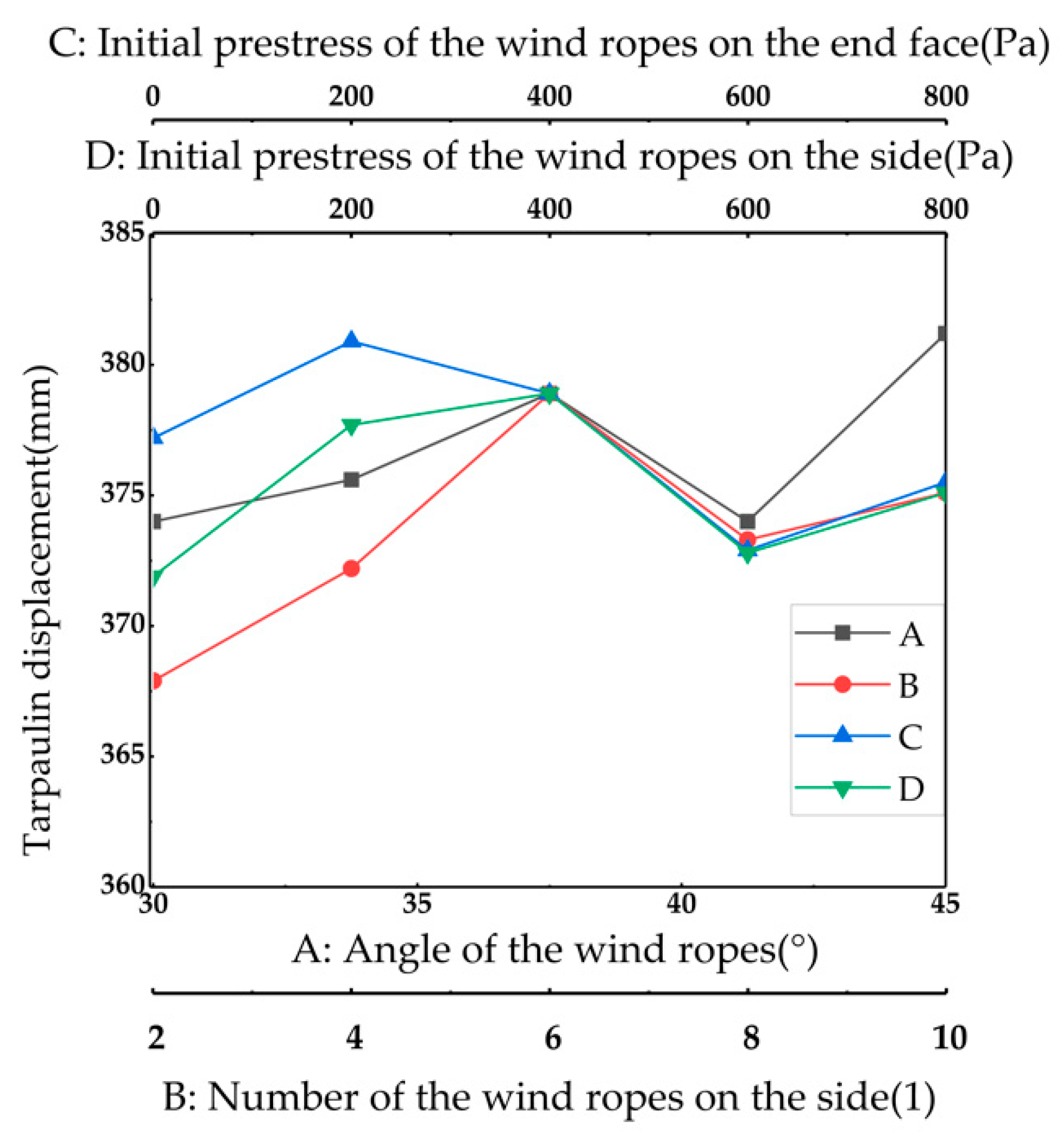
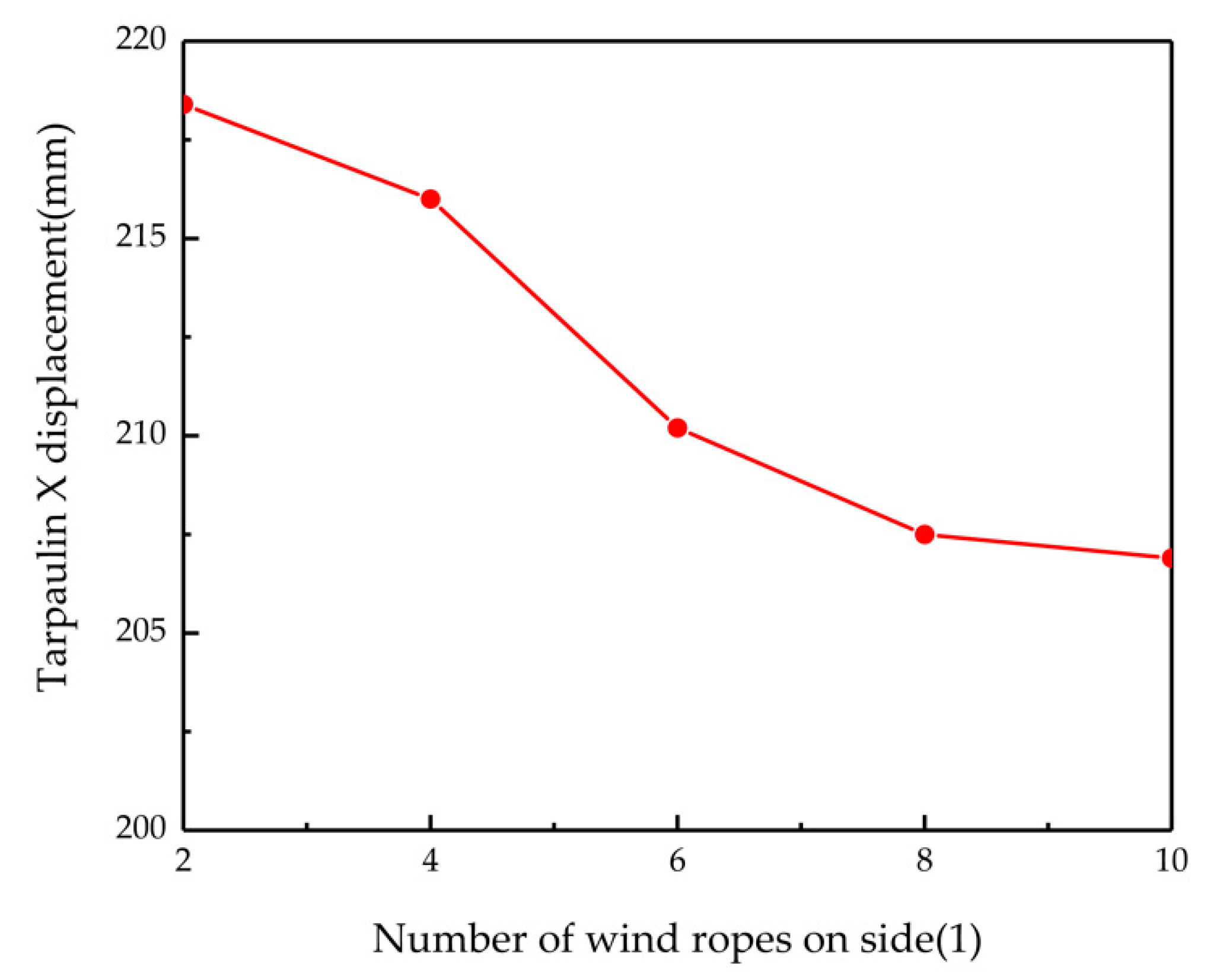
3.2. Analysis of Displacement Results

The curves of displacement of the tent are shown in Figure 8. The maximum displacement occurs at the top of the tarpaulin. Due to the difference between the stiffness of the tarpaulin and the air rib, the pocket effect appears in the middle position of the air rib.
The relationship between the angle of the wind ropes and the total maximum displacement of the tarpaulin is shown in Figure 8 (A). With the increase in the angle, the displacement of the tarpaulin increases at first, and then decreases. The Y direction component of the load on the tent, which is derived from the wind ropes, increases with the angle; however, the X direction component of the load on the tent decreases with the angle. The minimum displacement appears when the angle of the wind ropes is 41.25°. In order to minimize the displacement of the tarpaulin and improve its supporting capacity of the tent, the angles of the wind ropes are comprehensively considered to be 30°, 37.5°, and 45°for the next optimization test.
The relationship between the number of wind ropes on the side and the total maximum displacement of the tarpaulin is shown in Figure 8 (B). It can be seen that the displacement of the tarpaulin increases at first, and decreases with the increase in the number of the wind ropes on the side. When the wind ropes are fixed on the tarpaulin, the load is added to the tarpaulin in the same direction as the snow load. With the increase in the number of wind ropes on the side, the Y direction component of the load applied on the tarpaulin increases, and the displacement of the tarpaulin is larger. The wind ropes are fixed on the end face of the air rib, and when the number is two, they have little influence on the displacement of the middle of the tarpaulin. With the increase in the number of the wind ropes, the wind ropes approach the center position gradually. The displacement of the tent is maximum when six wind ropes are fixed on the tent. The displacement of the tarpaulin in the X direction is shown in Figure 9. It can be seen that the X direction displacement decreases with the increase in the number of wind ropes on the side. When more than six wide ropes are fixed on the tent, the total maximum displacement decreases. The closer the wind ropes are added to the center of the tarpaulin, the greater the displacement of the tarpaulin is. The influence of the number of wind ropes on the side on the maximum displacement under load is nonlinear. The numbers of the wind ropes on the side which are selected for the optimization analyses are 2, 6, and 10.
Figure 8 (C) shows the relationship between the initial prestress of the wind ropes on the end face, and the total maximum displacement of the tarpaulin. When the initial prestress of the wind ropes is less than 600 Pa, the maximum displacement of the tarpaulin decreases with the increase in the initial prestress of the wind ropes. When the initial prestress of the wind ropes on the end face is 600 Pa, the displacement of the tarpaulin is the minimum, and increases slightly with the increase in initial prestress of the wind ropes. Based on careful consideration, the initial prestresses of the wind ropes on the end face are determined to be 400 Pa, 600 Pa, and 800 Pa for the optimization test.
Figure 8 (D) shows the relationship between the initial prestress of the wind ropes on the side, and the total maximum displacement of the tarpaulin. When the initial prestress of the wind ropes is less than 400 Pa, the maximum displacement of the tarpaulin decreases with the increase in the initial prestress of the wind ropes. When the initial prestress of the wind ropes on the side is 600 Pa, the displacement of the tarpaulin is the minimum. The initial prestresses of the wind rope on the side are determined to be 0 Pa, 100 Pa, and 200 Pa for the optimization test.

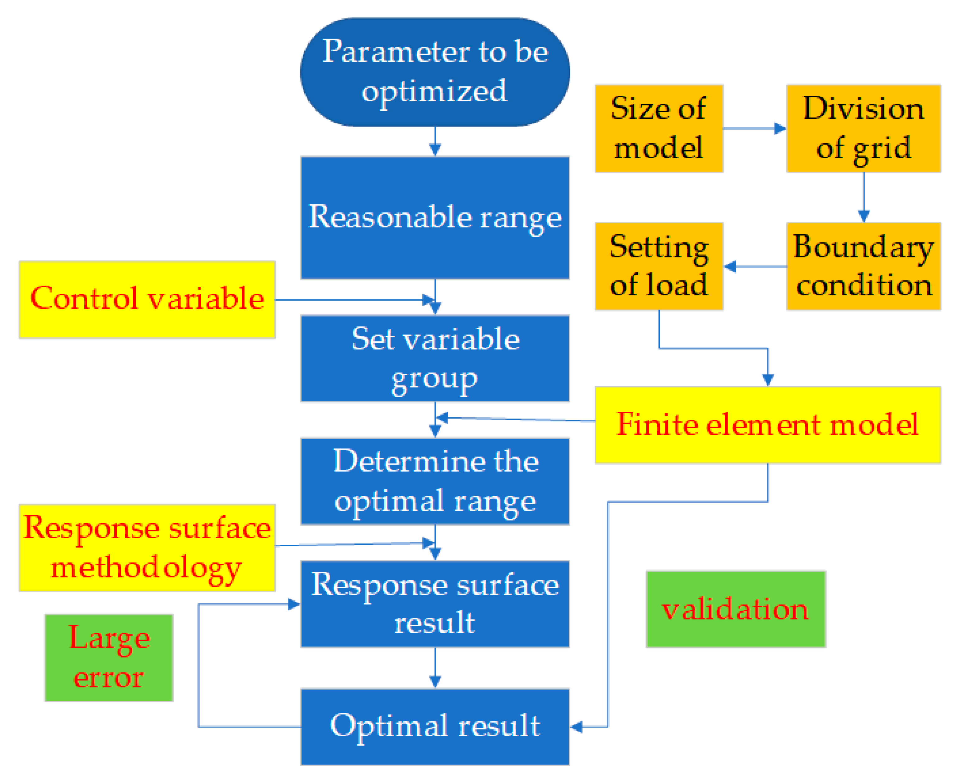
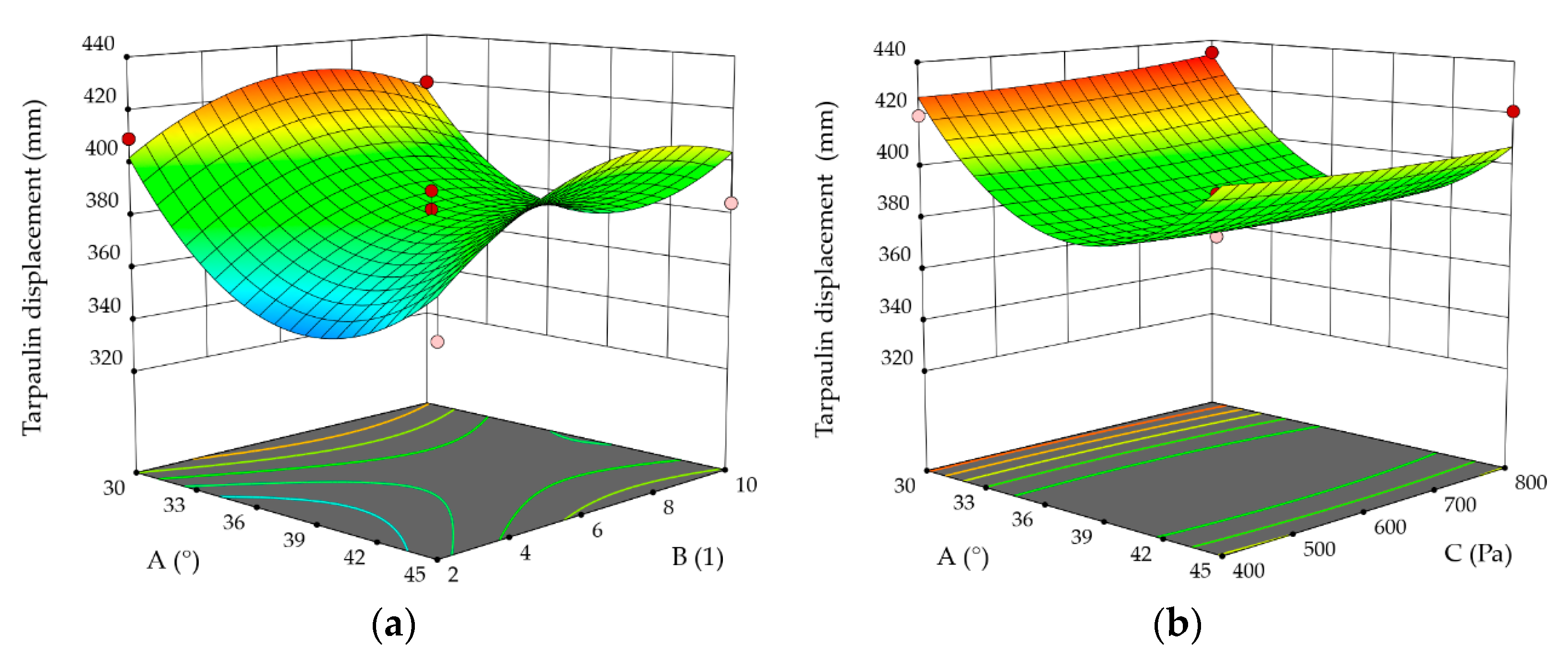
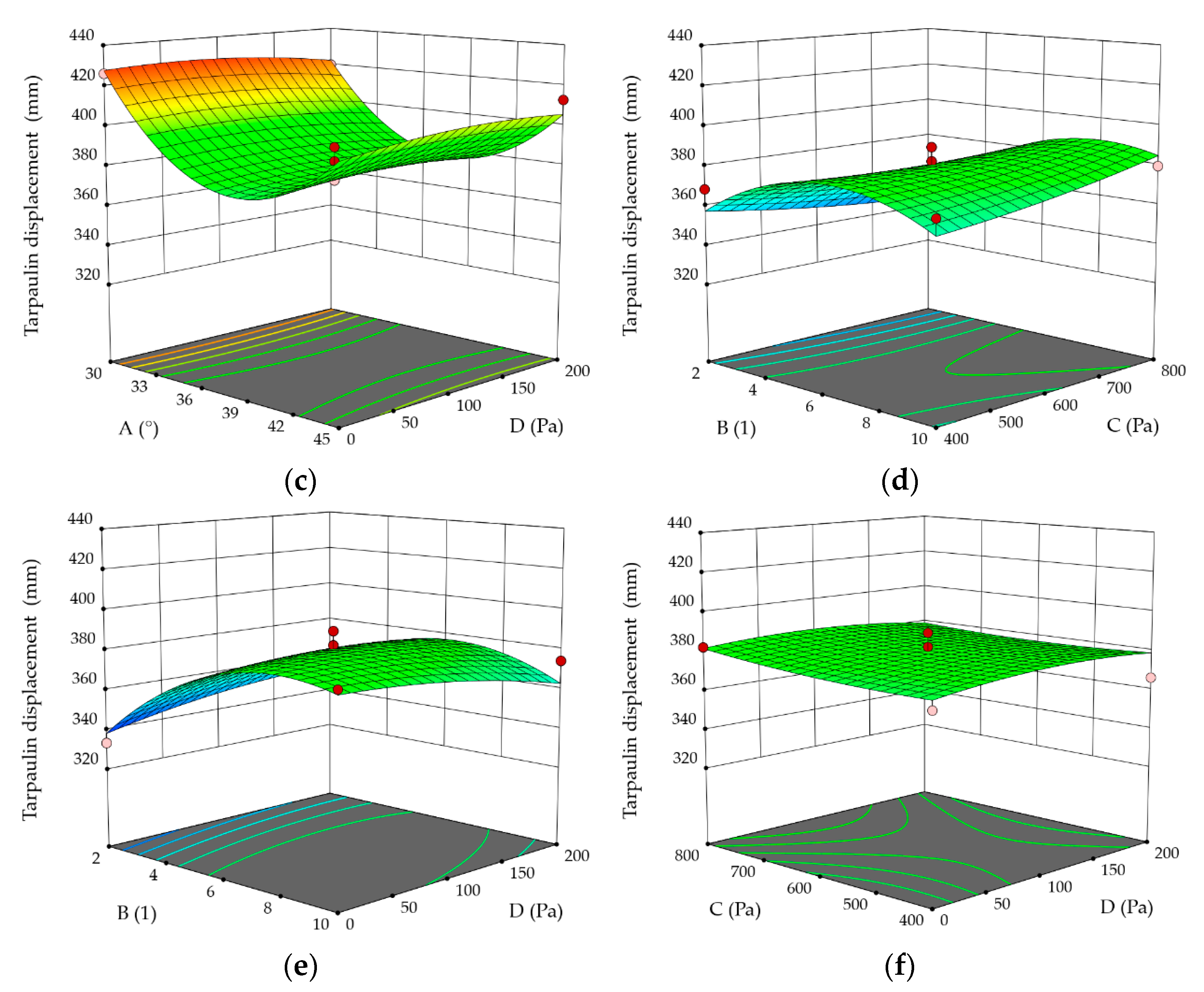
4. Optimized Design of the Wind Ropes Parameters Based on the Response Surface Methodology

The effect of a single factor on the stress and the displacement of the tarpaulin can be obtained by the single-factor analysis method. The results show that the parameters of the wind ropes have little influence on the stress. The decline in displacement can increase the effective space and improve safety. Therefore, the response surface methodology is used to analyze the implicit relationship between the parameters and the maximum displacement by Design-Expert 12 (Stat-Ease Inc., Minneapolis, MN, USA).

4.1. Optimization of Programmed Design

The angle of the wind ropes, the number of the wind ropes on the side, the initial prestress of the wind ropes on the end face, and the initial prestress of the wind ropes on the side have been considered as the most important factors for response surface methodology. The maximum displacement of the tarpaulin is the target parameter. The test plan is defined by the central composite design method (CCD; four factors and three levels; Table 3). Each trial is performed twice. The corresponding results are presented in Table 4 and Figure 10.

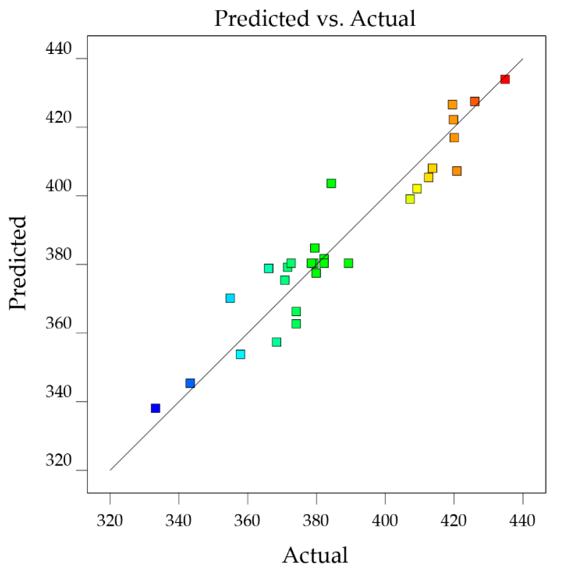
4.2. Analysis of the Results

The simulation results of the CCD are fitted with a second-order polynomial equation. The fitted equation is shown as follows (3):
X = 382.20 − 11.32A + 12.08B + 0.2333C + 1.63D + 4.65AB + 2.90AC − 2.05AD − 7.62BC + 7.62BD − 1.47CD + 35.75A2 −19.75B2 − 4.42C2 + 1.00D2
where X is the maximum displacement of the tent. A, B, C, and D are the values of four parameters, respectively (the angle of the wind ropes, the number of the wind ropes on the side, the initial prestress of the wind ropes on the end face, and the initial prestress of the wind ropes on the side). The coefficient means the influence weight of each parameter on the maximum displacement. Once the values of the four parameters are determined, the value of the maximum displacement can be predicted according to the equation.
As shown in Figure 11, the maximum displacements calculated by the simulation are concentrated on the regression line. The error value between the predicted value and the calculated value is less than 3.5%. For the experimental model, F = 10.21, p < 0.0001, the fitted equation meets good relevancy. It is significant to analyze the variance of the simulation data. From the equation coefficient, it is known that A (the angle of the wind ropes) and B (the number of the wind ropes on the side) have a significant influence on the maximum displacement of the tent. The two parameters’ p-values are less than 0.05.
The two-dimensional contour plots are shown in Figure 12. Figure 12a represents the effect of the angle of the wind ropes and the number of the wind ropes on the side, on the maximum displacement of the tent. It can be seen that the relationship between the angle of the wind ropes and the number of the wind ropes on the side is significant. The effect of the angle on the maximum displacement of the tent decreased with increasing the number of the wind ropes on the side. When two wind ropes are fixed on the end face of the tarpaulin, the angle of the wind ropes has a significant influence on the displacement of the air rib on the end face. With increasing the number of the wind ropes, the wind ropes distribute uniformly, the force which distributes on the air ribs decreases, so the displacement decreases.
Figure 12b,c represent the relationship between the angle of the wind ropes and the initial prestress of the wind ropes on the end face, and the initial prestress of the wind ropes on the side, respectively. When the initial prestress of the wind ropes is fixed, the maximum displacement decreases at first, and increases with the increase in the angle of the wind ropes. The influence trend of the angle of the wind ropes on the maximum displacement changes little with the initial prestress of the wind ropes on the end face and the initial prestress of the wind ropes on the side. It can be seen from Figure 12f that the relationship between the initial prestress of the wind ropes on the end face and the initial prestress of the wind ropes on the side is poor. The slope of the response surface curve is gentle. With the increase in the initial prestress of the wind ropes on the end face, the maximum displacement changes little with the initial prestress of the wind ropes on the side.
Figure 12d,e represent the relationship between the number of the wind ropes on the side and the initial prestress of the wind ropes on the end face, and the initial prestress of the wind ropes on the side, respectively. It can be seen that the relationship between the two parameters is weak.
According to the results of the simulation data, the optimal scheme parameters are determined as follows: the angle of the wind ropes is 41°, the number of the wind ropes on the side is 2, the initial prestress of the wind ropes on the end face is 800 Pa, and the initial prestress of the wind ropes on the side is 0 Pa. To confirm the accuracy of the model in the optimum conditions, an additional experiment is performed in the optimum conditions.

5. Validation of the Results in the Optimum Conditions

The simulation model is established according to the optimal parameters which are determined by the response surface methodology, and the calculation results are shown in Figure 13. The maximum displacement of the tarpaulin is 329.7 mm, and the difference between the result (332.5 mm), which is estimated by the response surface equation, is 0.84%. The difference between the maximum displacement of the tarpaulin which is calculated at the optimum condition, and that which is calculated by the single factor method is 10.2%. The maximum displacement of the air rib is 237.1 mm. The maximum Von Misses stress of the tarpaulin is 48.78 MPa, and the maximum Von Misses stress of the air rib is 17.17 MPa. They are all within the allowable strength of the tarpaulin and the air ribs.

6. Conclusions

The air-rib tents are widely used because they are lightweight and site adaptable, but the large deformation of these tents reduces their effective space. It is significant to reduce the displacement of the air-rib tent by parameter optimization. Four external parameters of the tent’s wind ropes, which are studied in the paper, are the angle of the wind ropes, the number of the wind ropes on the side, and the initial prestress of the wind ropes on the side or end faces. The effect of the wind rope on the Von Misses stress and the displacement under load is studied by the finite element method, and the response surface methodology is used to minimize the displacement of the tent. The results are only applicable to the specific geometry and the size of the tent. The tents of other sizes and structures will be optimized in the future.
The effect of the wind ropes on the maximum displacement of the tent is stronger than that on the Von Misses stress of the tent under the external load. The angle of the wind ropes and the number of the wind ropes on the side are the two most significant parameters which affect the displacement of the tent. With the increase in the angle, the displacement of the tarpaulin increases at first, and then decreases. The minimum displacement appears when the angle of the wind ropes is 41.5°. The closer the wind ropes are added to the center of the tarpaulin, the greater the displacement of the tent is. The influence of the number of the wind ropes on the maximum displacement under load is nonlinear.
Based on the analysis using the response surface methodology, the relationship between the angle of the wind ropes and the number of the wind ropes on the side is significant. The effect of the angle of the wind ropes on the maximum displacement of the tent decreased with increasing the number of the wind ropes on the side. The optimal parameters are as follows: the angle of the wind ropes is 41°, the number of the wind ropes on the side is two, the initial prestress of the wind ropes on the end face is 800 Pa, and the initial prestress of the wind ropes on the side is 0 Pa. In the condition with the optimal parameters, the maximum displacement reduces by 10.2%, and the maximum stress barely changes.
It can be concluded from the results that the external factors have a significant effect on the maximum displacement of the tent. The maximum displacement can be reduced by changing the angle of the wind ropes and the number of the wind ropes on the side, if the structural parameters of the tent are fixed. The best values of the external factors can be used to increase the effective space of the air-rib tents.

Author Contributions

Conceptualization, Y.L. and Y.R.; methodology, J.Z.; software, Y.L. and Y.R.; validation, Y.L. and Y.R.; formal analysis, Y.L. and Y.R.; investigation, L.Z., S.L. and X.C.; resources, F.L. and J.Z.; data curation, Y.R.; writing—original draft preparation, Y.R.; writing—review and editing, Y.L. and S.L.; visualization, Y.R.; supervision, F.L., L.Z., J.Z. and X.C.; project administration, L.Z. and J.Z.; funding acquisition, J.Z. All authors have read and agreed to the published version of the manuscript.

Funding

This research was funded by the Open Research Fund Program of Beijing Engineering Research Center of Monitoring for Construction Safety, grant number BJC2020K011; Young Teachers’ Research Ability Enhancement Program Project of Beijing University of Civil Engineering and Architecture, grant number X21059.

Institutional Review Board Statement

Not applicable.

Informed Consent Statement

Not applicable.

Data Availability Statement

Not applicable.

Conflicts of Interest

The authors declare no conflict of interest.

References

  1. Jiang, C.; Shi, X. “Quick-create” architecture: The research mainly about tent, a kind of quick-build architecture. Huazhong Archit. 2010, 28, 69–72. [Google Scholar]
  2. Zhao, X. Experimental Study and Analysis on the Air-Inflated Arch. Master’s Thesis, Chang’an University, Xi’an, China, 2007. [Google Scholar]
  3. Huang, H.; Li, X.; Xue, S.; He, Y.; Li, J. Study on the structure selection of air-tight tent with air-supported and air-inflated composite structure. Build. Struct. 2021, 51, 577–582. [Google Scholar]
  4. Feng, Y.; Yan, W.; Yin, J.; Yang, F. Mechanical property analysis and test of air-rib inflatable tent. In Proceedings of the Celebrating the 80th Anniversary of Professor Liu Xiliang and the Proceedings of the Eighth National Symposium on Modern Structural Engineering, Beijing, China, 19–22 July 2008. [Google Scholar]
  5. Kaveh, A.; Rezaei, M. Optimum topology design of geometrically nonlinear suspended domes using ECBO. Struct. Eng. Mech. 2015, 56, 667–694. [Google Scholar] [CrossRef]
  6. Guo, X.; Li, Q.; Zhang, D.; Gong, J. Structural behavior of an air-inflated fabric arch frame. J. Struct. Eng. 2016, 142, 4015108.1. [Google Scholar] [CrossRef]
  7. Pilarska, D.; Maleska, T. Numerical analysis of steel geodesic dome under seismic excitations. Materials 2021, 14, 4493. [Google Scholar] [CrossRef] [PubMed]
  8. Nilson, B.; Roberto, D.; Lucas, S.V.; Key, F.L.; Diego, R. Dynamic behavior of the geodesic dome joints. Int. J. Comput. Appl. 2016, 140, 40–44. [Google Scholar]
  9. Cui, J.; Tang, Y.; Long, L. Wind-induced vibration analysis of a long-span framework membrane structure. Build. Struct. 2007, 37, 32–35. [Google Scholar]
  10. Wu, B.; Wu, Y.; Dai, J.; Sun, Y. Design and construction analysis of long-span dry coal shed cable arch truss. Build. Struct. 2021, 51, 546–555. [Google Scholar]
  11. Li, X.; Huang, H.; Xue, S.; He, Y.; Li, J. Study on mechanical behavior of air-tight inflatable tent structures. Spat. Struct. 2021, 27, 50–55+49. [Google Scholar]
  12. He, Z.; Ding, J.; Su, X. Characteristic of wind load and static wind effects analysis of membrane structure canopy roof of large-scale stadium. J. Tongji Univ. Nat. Sci. 2007, 8, 1019–1024. [Google Scholar]
  13. He, Z.; Ding, J.; Chao, S.; Xiao, X. Structural design of large-span pre-stressed truss shell system of Beijing university-table tennis gymnasium for the 2008 Olympic Games. Build. Struct. 2008, 3, 55–60. [Google Scholar]
  14. Wang, L. The Response Surface Method in Structural Optimization Study on the Application. Master’s Thesis, Shanghai Ocean University, Shanghai, China, 2018. [Google Scholar]
  15. Diniz, C.A.; Méndez, Y.; de Almeida, F.A.; da Cunha, S.S., Jr.; Gomes, G.F. Optimum design of composite structures with ply drop-offs using response surface methodology. Eng. Comput. 2021, 38, 3036–3060. [Google Scholar] [CrossRef]
  16. Betül, S.Y. Optimal design of automobile structures using moth-flame optimization algorithm and response surface methodology. Mater. Test. 2020, 62, 371–377. [Google Scholar]
  17. Rahul, N.; Ramachandran, K.I. Design and optimization of automotive energy absorber structure with functionally graded material. Mater. Today Proc. 2018, 5, 25640–25648. [Google Scholar]
  18. Zhao, J.; Li, J.; Huang, C. Multi-objective Optimization Model of Hydrodynamic Sliding Bearing Based on MOPSO with Linear Weighting Method. IAENG Int. J. Comput. Sci. 2021, 3 Pt 3, 48. [Google Scholar]
  19. Saka, M.; Optimum, P. topological design of geometrically nonlinear single layer latticed domes using coupled genetic algorithm. Comput. Struct. 2007, 85, 1635–1646. [Google Scholar] [CrossRef]
  20. Kaveh, A.; Amirsoleimani, P.; Dadras, E.A.; Rahmani, P. Frequency-constrained optimization of large-scale dome-shaped trusses using chaotic water strider algorithm. Structures 2021, 32, 1604–1618. [Google Scholar] [CrossRef]
  21. Holly; Liu, Q. Multi-Objective Optimization Theory and Continuous Method, 1st ed.; Science Press: Beijing, China, 2015. [Google Scholar]
  22. Chen, H.; Peng, C.; Tian, K.; Wang, L. Optimal design for truss structure shape based on response surface method. Chin. J. Eng. Des. 2018, 25, 457–464. [Google Scholar]
  23. Wang, Y.; Wang, C. Theory and application of response surface methodology. J. Minzu Univ. China (Nat. Sci. Ed.) 2005, 14, 236–240. [Google Scholar]
  24. Peng, K.; Li, X.; Peng, S.; Dong, L.; Yao, Y. Optimization of frame stope structure parameters based on response surface method in under-sea mining. J. Cent. South Univ. 2011, 42, 2417–2422. [Google Scholar]
  25. Zhan, Y.; Hou, Z.; Shao, J.; Zhang, Y.; Sun, Y. Cable force optimization of irregular cable-stayed bridge based on response surface method and particle swarm optimization algorithm. Bridge Constr. 2022, 552, 16–23. [Google Scholar]
  26. Zhu, Z.; Li, X.; Li, Z.; Chen, Q.; Cai, Y.; Peng, M. Optimization design of perforated panel for composite ships based on response surface methodology. Ship Sci. Technol. 2022, 44, 48–52. [Google Scholar]
  27. Cheng, D.; Cao, J.; Gao, P. Mechanical performance analysis of special-shaped columns strengthened with CFRP cloth strips. Archit. Sci. 2022, 9, 143–150. [Google Scholar]
  28. Li, Y.; Xie, Q.; Zhang, X.; Zhang, J. Cascading Failure Analysis of Transmission Tower-Line System under Strong Wind. Journal of Southwest Jiaotong University. Available online: http://kns.cnki.net/kcms/detail/51.1277.U.20221110.1233.004.html (accessed on 10 November 2022).
  29. Du, X.; Zhang, K.; Zhang, R.; Ye, T.; Yi, W.; Jiang, J. Dynamic Modeling and Analysis of Space Membrane Structure Based on Constant Strain Element. China Space Science and Technology. Available online: http://kns.cnki.net/kcms/detail/11.1859.V.20220829.1010.002.html (accessed on 29 August 2022).
  30. Li, Y. Study and Applications on Mechanical Properties of Membrane Materials and Structures. Master’s Thesis, Tongji University, Shanghai, China, 2007. [Google Scholar]
  31. Zhuo, X.; Dong, S. Cantilever erection method and analysis of construction internal forces for large-span spherical reticulated shells. J. Zhejiang Univ. (Eng. Sci.) 2002, 2, 36–39. [Google Scholar]
  32. Li, Q. Analysis on Inflation Deployment and Deflation Collapse of Air-Inflated Fabric Arch Structures. Master’s Thesis, Shanghai Jiaotong University, Shanghai, China, 2016. [Google Scholar]
Figure 1. The shape and arrangement of the tents [3,4]: (a) the arched-rib tent; (b) the broken-line rib tent; reprinted with permission from Ref. [3]. 2021, Hang Haonan. (c) The vertical type tent; (d) the curved type tent. Adapted with permission from Ref. [4]. 2008, Feng Yuanhong.
Applsci 13 00055 g001
Figure 2. The finite element model of the separated air-rib tent. (a) The tarpaulin; (b) the air rib; (c) the cross section of an air rib.
Applsci 13 00055 g002
Figure 3. The finite element model of the separated air-rib tent. (a) The tarpaulin grid; (b) the air rib grid.
Applsci 13 00055 g003
Figure 4. The schematic diagram of the coefficient of the wind load and direction of the snow load. (a) The wind load; (b) the snow load.
Applsci 13 00055 g004
Figure 5. The process flowchart of the proposed methodology.
Applsci 13 00055 g005
Figure 6. The influence of a single parameter on the Von Misses stress of the tarpaulin.
Applsci 13 00055 g006
Figure 7. The maximum Von Misses stress of the tent. (a) The Von Misses stress of the tarpaulin; (b) the Von Misses stress of the ribs.
Applsci 13 00055 g007
Figure 8. The influence of a single parameter on the displacement of the tarpaulin.
Applsci 13 00055 g008
Figure 9. The influence of the number of the wind ropes on the displacement of the tarpaulin in X direction.
Applsci 13 00055 g009
Figure 10. The results of the response surface methodology.
Applsci 13 00055 g010
Figure 11. The comparison between the results of the numerical simulation and the predicted results of the response surface methodology. (The color of the points, which are set in the figure, changes from blue to red with the increase in the values).
Applsci 13 00055 g011
Figure 12. The effect of different wind rope parameters on the displacement of the tarpaulin. (a) The angle of the wind ropes and the number of the wind ropes on the side; (b) the angle of the wind ropes and the initial prestress of the wind ropes on the end face; (c) the angle of the wind ropes and the initial prestress of the wind ropes on the side; (d) the number of the wind ropes on the side and the initial prestress of the wind ropes on the end face; (e) the number of the wind ropes on the side and the initial prestress of the wind ropes on the side; (f) the initial prestress of the wind ropes on the end face and the initial prestress of the wind ropes on the side. (In the figure, the red circle means the value of the displacement of the tarpaulin is large, while the pink circle means the value of the displacement of the tarpaulin is small).
Applsci 13 00055 g012aApplsci 13 00055 g012b
Figure 13. The simulation results of the tent in the optimal conditions. (a) The displacement of the tarpaulin; (b) the displacement of the air ribs; (c) the Von Misses stress of the tarpaulin; (d) the Von Misses stress of the air ribs.
Applsci 13 00055 g013
Table 1. The property parameters of two kinds of tent materials.
PartThickness
(mm)
Density
(g/cm3)
Elastic Modulus
(GPa)
Poisson’s RatioFracture Strength
(MPa)
Tarpaulin0.271.0000.9400.35178.33
Air rib2.601.0690.4700.32119.47
Table 2. The test scheme for exploring the influence of a single variable.
ParametersAngle of the
Wind Ropes
(°)
Number of the Wind
Ropes on the Side
(1)
Initial Prestress of the Wind
Ropes on the End Face
(Pa)
Initial Prestress of the Wind
Ropes on the Side
(Pa)
Case 130/33.75/37.5/41.25/456400400
Case 237.52/4/6/8/10400400
Case 337.560/200/400/600/800400
Case 437.564000/200/400/600/800
Table 3. The table of the research parameters.
Factor CodeParameter NameParameter Value
−10+1
AAngle of the wind ropes 30°37.5°45°
BNumber of the wind ropes on the side 2610
CInitial prestress of the wind ropes on the end face400 Pa600 Pa800 Pa
DInitial prestress of the wind ropes on the side 0 Pa100 Pa200 Pa
Table 4. The table of the design values of the test plan.
Serial
Number
A
(°)
B
(1)
C
(Pa)
D
(Pa)
Displacement of the Tarpaulin (mm)
1302600100409.2
2452600100354.9
33010600100420.0
44510600100384.3
537.564000370.8
637.56400200366.1
737.568000382.2
837.56800200371.6
9306400100419.5
10456400100413.7
11306800100434.8
12456800100420.8
1337.526000333.2
1437.5106000379.9
1537.52600200357.9
1637.510600200374.1
173066000426.0
184566000407.2
19306600200419.8
20456600200412.6
2137.52400100368.4
2237.510400100374.1
2337.52800100343.3
2437.510800100379.5
2537.56600100379.2
2637.56600100382.2
2737.56600100378.5
2837.56600100372.6
2937.56600100389.3
Disclaimer/Publisher’s Note: The statements, opinions and data contained in all publications are solely those of the individual author(s) and contributor(s) and not of MDPI and/or the editor(s). MDPI and/or the editor(s) disclaim responsibility for any injury to people or property resulting from any ideas, methods, instructions or products referred to in the content.

