Article

Design and Test of Sowing Depth Measurement and Control System for No-Till Corn Seeder Based on Integrated Electro-Hydraulic Drive

1
College of Mechanical and Electrical Engineering, Qingdao Agricultural University, Qingdao 266109, China
2
National Key Laboratory of Agricultural Equipment Technology, Beijing 100083, China
3
College of Engineering, China Agricultural University, Beijing 100083, China
*
Author to whom correspondence should be addressed.
Appl. Sci. 2023, 13(10), 5823; https://doi.org/10.3390/app13105823
Submission received: 9 April 2023 / Revised: 27 April 2023 / Accepted: 28 April 2023 / Published: 9 May 2023

Abstract

:
An electro-hydraulic profiling mechanism has been gradually applied to provide suitable downforce for a no-till row unit and to ensure the consistency of the seed sowing depth. In order to improve the control effect of the sowing depth system and solve the problems of a complex structure, scattered valve sets and equipment suitability of an existing electro-hydraulic row unit, this paper takes the 2BJ-470B no-till row unit as the carrier and innovatively designs an integrated pressure-reducing cylinder (IPRC) based on electro-hydraulic technology by analyzing the sowing depth control process of an electro-hydraulic seeder. In addition, we develop the integrated electro-hydraulic-driven sowing depth measurement and control system. Combined with the feedforward compensation PID control algorithm, the dynamic regulation of the downforce is realized with the IPRC. The field test shows that under the setting of a sowing depth of 50 mm and a vehicle speed of 9~10 km·h−1, the qualified rate of the sowing depth under the three adjustment methods of self-weight adjustment, spring adjustment and electro-hydraulic adjustment is 89.2%, 96.7% and 98.6%, respectively, and the corresponding maximum coefficient of variation of the sowing depth is 16.7%, 12.9% and 6.4%, respectively. The seed groove environmental qualification rate (SFEQ) is further analyzed in combination with the soil compaction, and the mean values of the qualification rates of the three control methods at different vehicle speeds are 88.3%, 91.6% and 98.6%, respectively. The integrated electro-hydraulic-driven row unit has significant advantages over mechanical and self-weight regulation, and its whole machine integration degree and high adaptability realize the comprehensive control of the sowing depth and soil compaction strength.

1. Introduction

Precision sowing techniques have long been a specific requirement for achieving precision seeding [1,2], and site-specific precision sowing techniques have a key role in promoting maize root development and improving maize yield [3,4]. The sowing depth consistency, as one of the important indicators of the precision sowing level, is influenced by factors including the surface straw cover density, soil texture changes and topographic changes [5,6,7]. Especially since the development of conservation tillage technology, the amount of straw residue cover in the field has increased greatly, resulting in the inability of the seeder to obtain sufficient downforce to ensure a stable groove depth [8,9].
Downforce is the load applied to the row unit, including the self-weight of the unit and the additional load applied by the profiling mechanism, which is vertically downward and plays a vital role in maintaining a stable and consistent sowing depth [10]. The soil compaction force of the row unit is the remaining load after the downforce systems have applied enough force to engage the disk openers to the target sowing depth and is referred to as the gauge wheel load [11].
However, applying more downward pressure than expected will inevitably result in an overload of the soil compaction force, and it can easily cause excessive compaction of the seed groove. This makes it difficult for the seeds to penetrate the wall for rooting and germination and affects the consistency of corn emergence [12,13]. In the face of the complex and variable external soil environment, it is necessary to strengthen the research on the control of the row unit downforce.
In most areas of the country, mechanical profiling row units are still used, and the downforce of these units is limited by the performance of the springs. The number of springs and the pretightening force need to be adjusted manually according to the actual soil conditions before operation [14]. However, the spring mechanism cannot precisely control the value of the downforce in the face of a complex soil environment, nor can it better suppress the vibration of the machine caused by ground heaving, which is likely to cause problems, such as too shallow seed grooves and regional soil compaction. In order to realize the automatic regulation of the downforce, scholars mostly use hydraulic or pneumatic methods to manage the downforce of seeders [15].
Both hydraulics and pneumatics are the application of fluid power. Hydraulic systems use liquids such as oil to transmit power, whereas pneumatic systems use air to transmit power. A pneumatic system has a cleaner energy source, and its structure is relatively simple. The unlimited supply of air and the ease of compression make pneumatics widely used by agricultural machinery [16,17].
Karayel et al. [18,19,20] developed a sowing depth measurement model to adjust the downforce of the row unit by airbag actuation. It is able to maintain a better sowing depth consistency than mechanical downforce regulation. Gao et al. [21] developed the sowing depth quality monitoring and evaluation software based on the pneumatic downforce adjustment device. Tests were conducted at a 6 to 10 km·h−1 vehicle speed and the sowing depth data were measured: the mean, pass rate, standard deviation and coefficient of variation were 50.01 mm, 78.9%, 8.95 mm and 17.9%, respectively.
Air for pneumatic use is easier to obtain, but on seeders, oil for the hydraulic system can be supplied directly from the tractor system. For hydraulic drives, it is equally convenient and easy. Compared to pneumatics, hydraulics can handle higher loads than pneumatics. Moreover, hydraulics are more accurate and stable than pneumatics in controlling the stroke of the seeder profiling mechanism [22]. Therefore, hydraulically driven profiling devices have been widely studied by scholars [23].
Nielsen et al. [24,25,26] designed a sowing depth measurement and electro-hydraulic control system to compare three downforce control algorithms, and the variability in the sowing depth measured in field experiments was reduced from 8 mm to 2 mm.
Fu et al. [27] performed a digital modeling simulation of the electro-hydraulic system to determine the PID controller parameters and investigated the dynamic characteristics of the system. The results of the field static tests of the system performance showed that the system overshoot was ≤29.0% and the control error was ≤5.0%.
Wen et al. [28,29,30] used an electro-hydraulic profiling device to obtain the sowing depth through sensors (e.g., ultrasonic sensors) and established a sowing depth monitoring model. The experiments verified that the electro-hydraulic profiling device can maintain a relatively stable sowing depth.
Bai et al. [31] comprehensively analyzed the control process of the sowing depth and compaction and designed the control system of the downforce and closing force based on hydraulic regulation. The user interface was built to allow the user to adjust and monitor the current downforce and closing force of the system in real time.
Through the above scholars’ studies, it can be found that the row unit downforce control system gradually matured, although there is more progress. However, most of the research is more independent, not yet combining sowing depth and compaction with the analysis, and it lacks comprehensive evaluation criteria of the seed groove environment. Secondly, the current electro-hydraulic profiling device is more scattered, complex and has a poorly integrated structure. Due to the narrow space of the four-bar linkage, the scattered hydraulic components not only affect the structure of the whole machine but also reduce the control effect of the downforce.
Well-known agricultural companies such as Precision sowing, John Deere, AgLeader, Kinze, etc., already have more mature products for seeder downforce control (DeltaForce, SureForce et al.) [32,33,34,35,36,37,38]. These more integrated products are not tailor-made for the seeder we studied due to the different conditions of use (e.g., tractor model, model adaptation, etc.). They suffer from a small number of structural problems as well as performance matching. On the other hand, we currently have less theoretical analyses on designing the electro-hydraulic profiling mechanisms. In addition, an in-depth analysis is also essential for the research on sowing depth–compaction comprehensive control.
For the above problems, through the force and motion analysis of the row unit, we designed the integrated pressure-reducing cylinder (IPRC) based on the model 470B seeder. In this study, we comprehensively analyzed the relationship between the sowing depth and soil compaction and proposed the seed groove environmental qualification rate (SFEQ) for characterizing the effect of the sowing depth and compaction. To achieve a smooth ride as well as a consistent depth, the adaptive PID depth control algorithm was developed based on the CoDeSys V3.5 programming environment. To meet the needs of users, we built an IPRC-driven sowing depth control program and the interactive interface. Through the dynamic adjustment of the IPRC, we aim to realize the real-time regulation and control of the downforce and solve the problem of a scattered profiling structure so as to achieve the purpose of comprehensive control of the sowing depth and compaction.

2. Materials and Methods

2.1. Row Unit Force Analysis

Before designing the sowing depth control system, to ensure the stability of the furrowing operation and the fluency of profiling, it is necessary to conduct a force analysis on the row unit and its key components. The no-till row unit’s ripple disc and double-disc coulter are rigidly connected to the frame, and they are the first to have contact with the soil during tillage. The gauge wheel arm generates the contact force FJC through the depth-limiting block of the sowing depth adjustment mechanism to limit the maximum sowing depth, and the height difference H between the gauge wheel and the coulter is the ideal sowing depth. As shown in Figure 1, for the purpose of force analysis and calculation, the force of the row unit in the vertical direction is taken as the research object, assuming that the sowing row unit uniform linear motion moves forward uniformly and straightly with the same sowing depth on the level ground surface and all the parts work normally under the ideal condition. The downforce is the action force. According to Newton’s third law, ignoring the friction at the hinge of the machine, the theoretical downforce applied to the row unit in the vertical direction at this time is
F X Y = F n y + F Q y G
where the sum of the positive force of the soil-contacting parts F n y is
F n y = F P y + F K y + F S y + F Z y
where FXY is the downforce, the current additional applied force on the ground, N; FQy is the tractor vertical traction force, N; G is the total weight of the current row unit, N; FPy is the ripple disc force reaction force, the support force of the coulter and residue wheels in the vertical direction, N; FKy is the furrow opening reaction force, the support force on the double-disc coulter in the vertical direction, N; FSy is the soil compaction reaction force, the support force on the gauge wheels in the vertical direction, N; and FZy is the furrow reaction force, the support force on the closing wheel in the vertical direction, N.
From Equations (1) and (2), it can be seen that the combined force of the hydraulic force FXY, gravity G and traction force FQy in the vertical direction is equal in size and opposite in direction to the combined forces of FPy, FKy, FSy and FZy. Because the four-bar linkage is floating profiling, the size of FQy is negligible. Among them, the ripple disc support reaction force FPy is related to the physical characteristics of the straw and mulching density, which gradually changes with the difficulty of breaking stubble. The coulter support reaction force FKy is related to the physical characteristics of the soil, which fluctuates up and down with the change in soil hardness and moisture content.
According to the mechanical analysis, it is known that the row unit uses the downforce of the whole machine as the working pressure required for stubble breaking and furrowing during tillage. When the seeder works in hard soil or thick vegetation cover, the required stubble-breaking and furrow-opening resistance rises, and the weight G decreases continuously due to the seed and fertilizer discharge, resulting in the change in the downforce required by the machine. At this time, in order to ensure uniform and consistent furrowing operation, the magnitude of the downforce should be adjusted appropriately to meet the operational requirements of the row unit for the downforce.
In addition, although it can ensure that the gauge wheel is close to the surface and can reach the sowing depth set by the user when providing enough downforce, in actual operation too much downforce will cause the deflection of the gauge wheel arm with a very small angle θb, i.e., the tendency of the gauge wheel to move to state Ⅱ, as shown in Figure 1. This phenomenon will cause excessive soil compaction, i.e., the compaction of the sidewall of the groove will increase, the groove environment will be damaged and it will be difficult for the seed to penetrate the sidewall and germinate.
In this paper, by introducing the hydraulic system as the external pressure source, according to the working principle of the profiling mechanism, as shown in Figure 1, to make the gauge wheel and the coulter maintain the sowing depth H and so there is no soil compaction phenomenon, at this time the hydraulic force FY needs to meet
cos θ a F Y = F X Y L f 1 L f
where FY is the hydraulic force, i.e., the current output hydraulic force of the cylinder, N; Lf1 is the hydraulic force arm, mm; Lf is the effective length of the profiling lower rod, mm; and θa is the cylinder tilt angle, the angle between cylinder axis and plumb line, °.
The above Equations (1)–(3) are combined to obtain the relationship between the output hydraulic force FY of the cylinder and the applied downforce FXY. It can be seen that the hydraulic force FY as the source of external pressure, after the transfer of the mechanical structure, should meet the required downforce FXY changes. In the process of sowing depth control, the downforce FXY changes constantly with internal and external factors. It is necessary to ensure the premise of good contact between the gauge wheel and soil, and to improve the level of downforce as much as possible, so as to avoid the excessive compaction of soil on the sidewall of the seed groove, in order to reduce the influence of the soil resistance and machine weight on the consistency of the sowing depth. From the force analysis, it is known that the contact force FJC indirectly reflects the change in the soil compaction force FSy. Therefore, the sowing depth can be measured and controlled by applying variable hydraulic pressure to the profiling mechanism.

2.2. System Overall Scheme Design

The sowing depth measurement and control system consists of three major parts: mechanical system, electric control system and hydraulic system. During operation, the system ensures a consistent sowing depth by monitoring and regulating the downforce.

2.2.1. System Composition

In this paper, based on the preliminary research, the 2BJ-470B maize no-till precision seeder was selected as the test platform, and the design was optimized and technically improved for the existing spring-like structure.
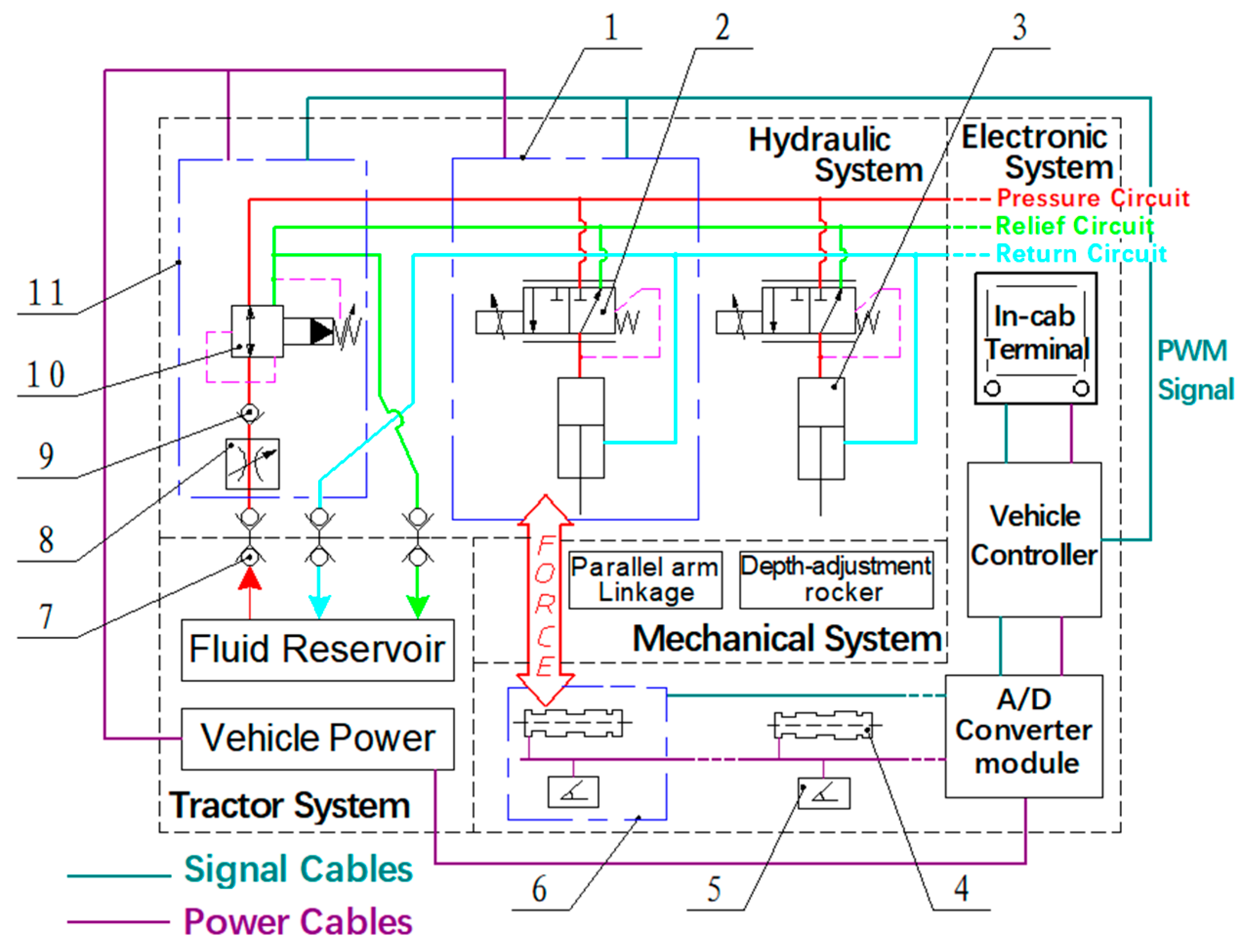
As shown in Figure 2, the whole machine system is divided into three parts: mechanical system, electric control system and hydraulic system. Among them, the mechanical system consists of four-bar linkage, a depth-limiting mechanism, a sowing depth adjustment mechanism, etc.; the electronic control system consists of a load pin, vehicle controller, vehicle display terminal, etc.; the hydraulic system consists of an integrated pressure-reducing cylinder, a main circuit valve group, etc. The tractor system is an external auxiliary system, in which the vehicle power supply provides power for the electronic control system, and the hydraulic oil tank provides the pressure source for the hydraulic system.

2.2.2. Basic Working Principle

The seeder forms a traction connection with the tractor through the crossbeam. During the sowing operation, due to the continuous changes in external factors (soil texture, stubble cover density) and internal factors (reduction in seed or fertilizer weight), the furrowing resistance changes with the plot, which is expressed as the support reaction force (i.e., the sidewall compaction force of seed groove) of the gauge wheel to the ground surface fluctuating up and down, and the consistency of the sowing depth is affected. Therefore, the axle pin and angle sensor are used to monitor the contact force and angle of the gauge wheel arm, respectively, so as to obtain the current sidewall compaction force indirectly. Transmit the monitoring data to the on-board control unit, judge the sowing depth status, compare with the set compaction force and perform the difference calculation at the same time. Run the PID control algorithm by PWM regulation to calculate the input current of the integrated pressure-reducing cylinder (IPRC) and adjust the output pressure in an intermittent way. The hydraulic force is applied to the mechanical system and transmitted to a series of soil-contacting parts so that it can work completely over the current soil resistance and realize the integrated control of the sowing depth and downforce. The tractor system acts as an external auxiliary system, providing power and pressure to the electrical and hydraulic systems of the whole machine.

2.3. Analysis of Sowing Depth Control Process

The sowing depth measurement and control system is based on the 470B unit design, and the control of the sowing depth involves the profiling mechanism and sowing depth adjustment mechanism. Therefore, the key components of the unit need to be analyzed.

2.3.1. Motion Analysis of the Profiling Mechanism

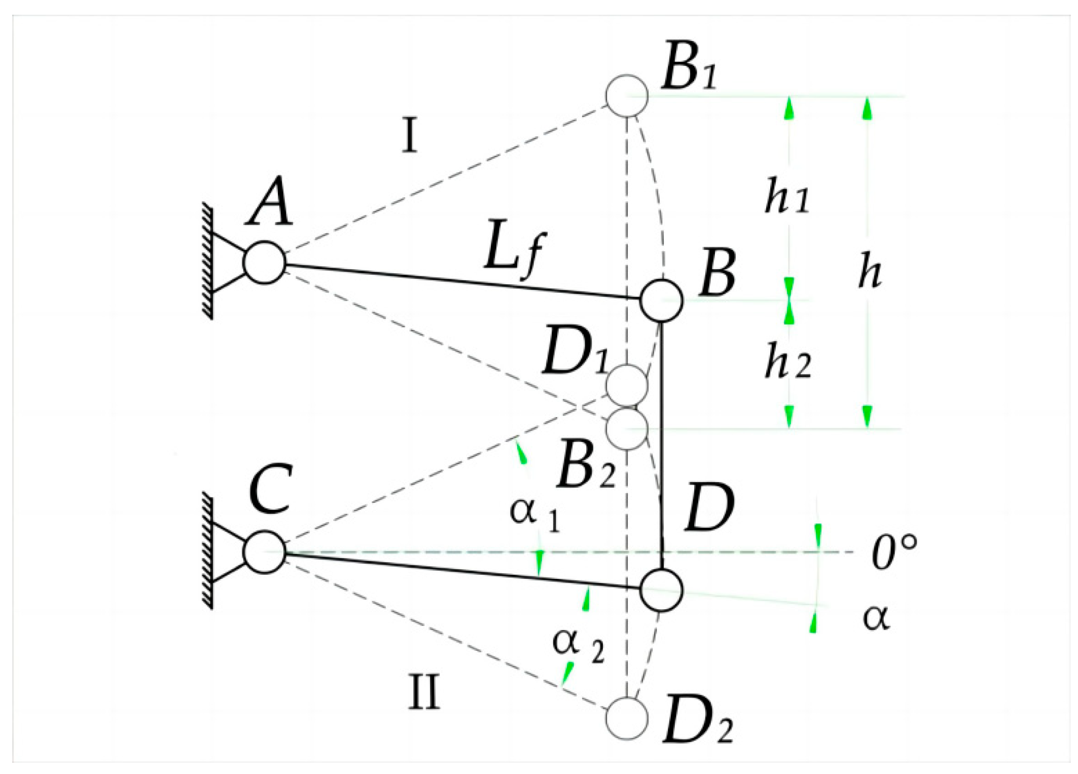
The range of profiling is a key parameter to characterize the profiling performance of the four-bar linkage, and the size of the profiling range determines the maximum range of the up and down floating profiling during the operation of the seeder. The main factors affecting the profiling performance of the four-bar linkage include the linkage length L, the upper profiling angle α1, the lower profiling angle α2, the traction angle α and so on. As shown in Figure 3, state Ⅰ and state Ⅱ correspond to the limit states of the upper and lower profiling angles, respectively.
The four-bar linkage is fixed at points A and C and hinged at points B and D. The AB and CD rods are the upper and lower rods of the profiling mechanism, respectively. When working, the BD rod floats up and down along the ground surface to maintain a consistent wheel stance when riding over uneven ground. The calculation formula of its profiling range is as follows:
h = L f ( sin α 1 + sin α 2 )
h = h 1 + h 2
where h is the total profiling range, mm; h1 is the upper profiling range, mm; h2 is the lower profiling range, mm; Lf is the length of the linkage of the four-bar linkage, mm; α1 is the upper profiling angle, °; α2 is the down profiling angle, °; and α is the traction angle, °.
From Formula (4), it can be seen that when the four-bar linkage moves up and down the same range of the profiling, the longer the length of the linkage, the smaller the range of the profiling angle changes. The change in traction angle depends on the direction of the tractor traction seeder frame. In order to ensure the stable work of the coulter during the sowing operation, the value of the traction angle should be as small as possible. According to the agronomic and other sowing requirements, the up and down profiling angles of the no-till seeder in general range from 6 to 22°, and the total profiling range h is 160 to 200 mm, of which the down profiling angle, as a key indicator for performance in varied terrain, has an actual profiling range of about 100 to 120 mm [39]. The effective length Lf of the 470B seeder linkage is 350 mm. The default size of the upper and lower profiling angles at a traction angle α of 0° is 16° and 20°. Substituting into Equations (4) and (5), we can obtain that the new profiling range h of the four-bar linkage is 215 mm.
The safety stroke Ssafe of the cylinder is the length of the cylinder when the profiling mechanism is in the maximum limit profiling; the safety stroke of the cylinder is generally less than the actual stroke of the cylinder. When designing the installation position of the cylinder, the relationship between the cylinder stroke and the range of profiling should be fully considered. When the four-bar linkage is in the upper and lower limit profiling state (the upper and lower linkages are stuck by the limit plate), the cylinder should be within the safe stroke. So as to avoid the damage of the cylinder when the seeder is transported, turn or limit the action. At the same time, the position of the fixed hole at the top of the cylinder determines the upper limit of the profiling when the cylinder is in the shortest state, and the position of the bottom hole of the cylinder along the lower rod determines the proportion of the profiling of the cylinder within the safe stroke. In other words, the closer the position of the bottom hole is to the top plate, the greater the hydraulic force and the shorter the cylinder stroke. See the cylinder profiling ratio Equation (6). It can be seen that the cylinder safety stroke is influenced by factors such as the force arm Lf1 or linkage length, and it determines the motion relationship between the cylinder and four-bar linkage.
S s a f e h = L f 1 L f
where Ssafe is the safe profiling stroke of the cylinder, mm; and Lf1 is the length of the equal force arm of the cylinder, mm.
According to the design principle of the profiling mechanism and the structure of the 470B row unit, we designed the cylinder bracket and the cylinder press plate. The cylinder bracket is connected with the top plate for clamping the top of the cylinder, and the cylinder press plate is connected with the original spring tie bar through bolts for mounting the bottom hole of the cylinder. The spring tie bar position, i.e., the cylinder iso-effective arm Lf1, is 105 mm, and the profiling ratio Lf1/Lf is 0.3. Due to the profiling of the space structure of the four-bar linkage, the safety stroke Ssafe of the cylinder is initially set to 55 mm in combination with the field conditions and usage scenarios, and the lower limit is used as the design benchmark, and the optimized total profiling range h0 is 183.3 mm, calculated by the profiling ratio Formula (6). As shown in Figure 4, the relative positions of the upper and lower limits of the four-bar linkage are shown. The piston rod of the cylinder is not fully extended when the profiling mechanism reaches the maximum profiling lower limit, and the upper and lower profiling angles α1 and α2 are 10.5° and 20°, respectively, and the upper and lower profiling ranges are 63.6 mm and 119.7 mm, respectively, which meet the design requirements of the profiling mechanism profiling range.
The cylinder platens on both sides apply downforce to the row unit by having contact with the four-bar linkage lower rod. The magnitude of the downforce is determined by the weight of the row unit, the tillage environment, the cylinder performance and other factors. Its extreme value determines the basic parameters, such as the material and size of the workpiece. The weight of the 470B row unit is about 90 kg. Combined with the literature [40,41] and the preliminary experimental study, it was found that the soil reaction force on the row unit was about 4000 N, when the sowing depth was set to 10 cm and the coefficient of variation of the sowing depth was small. Because the cylinder was installed vertically, the amount of variation in the working inclination θa was small. Ignoring the effect of θa on the hydraulic force, the hydraulic force FY at the IPRC is about 10.3 kN according to the conversion of Equation (3).

2.3.2. Mechanical Analysis of Sowing Depth Adjustment Mechanism

To facilitate the acquisition of the soil compressive force FSy, the depth-limiting contact force FJC between the gauge wheel arm and the depth-limiting block is monitored by a load pin.
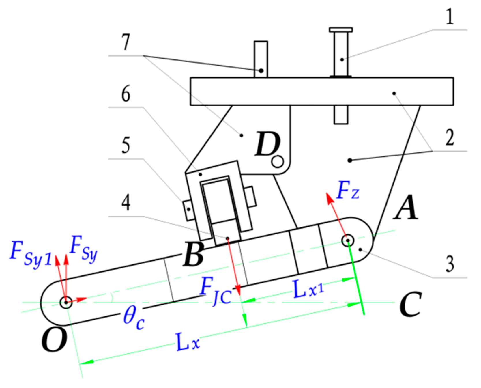
Figure 5 shows the structure of the sowing depth adjusting mechanism. Pulling the sowing depth adjusting handle can make the depth-limiting stopper move back and forth around the rotating axis D to adjust the target sowing depth. The load pin is installed in the contact position of the depth-limiting block and the gauge wheel arm, the periphery is wrapped in the depth-limiting block and fixed by the axle pin support, the gauge wheel arm and the gauge wheel are hinged in OA and the frame, respectively, and the working time of the gauge wheel arm swings around the point A and the contact limit with the depth-limiting block at the point B. The force analysis with point A where the gauge wheel arm is located as the research object shows that
F S y 1 L x + F J C L x 1 = 0
F S y 1 = F S y cos θ c
where FJC is the depth-limiting contact force, the contact force between the depth-limiting block and gauge wheel arm, and the direction is always perpendicular to OA, N; FSy1 is the fractional force of FSy in the vertical OA direction, N; Lx is the effective length of the gauge wheel arm, mm; Lx1 is the length of the force arm of FJC on OA, mm; and θc is the angle between the gauge wheel arm OA and the horizontal plane, °.
The value of the contact force FJC can be measured by the sensor, and its value reflects the degree of compaction of the sidewall of the seed groove by the gauge wheel, and it can also be used as the basis for judging the sowing depth: as shown in Figure 1, the row unit is in state II, the floating of the gauge wheel causes the sowing depth to be too shallow, the value of the contact force FJC is 0 and the compaction force FSy is only the weight of the gauge wheel. Unlike in state Ⅰ, FSy is the effective compressive force, if FSy is maintained at 300 N, and at this time, according to Equations (7) and (8), the greatest value of the contact force FJC is 300 N. To estimate the actual value of this contact force FJC, assuming that the impact force on the row unit due to surface heave is n times the mass of the row unit, the compressive force FSy at the gauge wheel is transformed into
F S y = ( n + 1 ) m max g
where mmax is the full-load mass of the row unit, kg; and g is the gravitational acceleration, take 9.8 m·s−2.
Joining Equations (7)–(9), the contact force FJC is obtained as
F J C = cos θ c ( 1 + n ) m max g L x L x 1
The measured mmax is about 120 kg, the angle θc of the gauge wheel arm in the minimum sowing state is 30° and the force arm action ratio Lx:Lx1 of the contact force FJC is 0.25. When n is taken as 2, the maximum contact force FJC is 8700.5 N when substituted into Equation (10).

2.4. Electro-Hydraulic Integrated Sowing Depth Measurement and Control System Design

The electro-hydraulic integrated sowing depth system is developed based on the 470B seeding unit and the system includes a hardware part and a software part. The IPRC is used as the downforce driver and the sowing depth control algorithm based on feedforward regulation runs on the control unit.

2.4.1. Hardware Design

(a)
Integrated Pressure-Reducing Cylinder (IPRC)
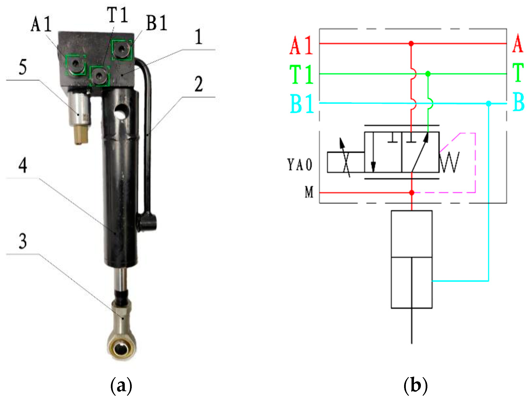
In order to facilitate the multi-row expansion and reduce the wiring and improve the system response speed, the electro-hydraulic IPRC is designed adaptively, which consists of a cartridge-type pressure-reducing valve and a single piston cylinder. As shown in Figure 6, the cylinder rod cavity is directly connected to the return path B, and the piston cavity is directly connected to the proportional pressure-reducing valve and connected to the inlet path A and the overflow path T. In the multi-row connection, each cylinder is interconnected with the oil port in the form of A-A1, B-B1 and C-C1 (Figure 6), eliminating the need for wiring between rows of valve groups and improving the integration of the system. When the IPRC is working, the coil YA0 is energized, and the left position of the solenoid valve is pressurized; when the power is lost, the right position is decompressed, and the spool is dynamically balanced, so that the hydraulic force is stabilized near the target value.
In Section 2.3.1, the theoretical hydraulic force value of at least 10.3 kN needs to be applied at the four-bar linkage. Taking into account the no-till sowing environment, seed and fertilizer consumption and other factors, the design is carried out according to the maximum thrust limit Pn of the cylinder which is 16 kN and the pressure drop ∆FY which is 12~16 kN within the range of the mechanical adjustment of the sowing depth. According to the safe stroke Ssafe of the cylinder which is 55 mm, the permissible stroke of the cylinder is determined as 60 mm and the installation distance is 30 cm. After consulting the work manual of the tractor, the oil supply pressure p of the tractor is selected as 16 MPa and the rated flow rate is 40 L·min−1.
The cylinder speed ratio is the area ratio of the rodless chamber to the rod chamber. Generally speaking, when the cylinder stroke is long and subject to thrust (piston rod extension when there is force), in order to improve the piston rod pressure stability, one should choose a higher cylinder speed ratio. We take the speed ratio factor of 1.38 commonly used in agricultural machinery. According to the design criteria of the hydraulic cylinder [42], the formula for calculating the hydraulic cylinder bore D is
D = 4 P n φ π p
where D is the hydraulic cylinder inner diameter, m; Pn is the hydraulic cylinder theoretical thrust, take 16 kN; p is the system oil supply pressure, take 16 MPa; and φ is the speed ratio coefficient, take 1.38.
The calculation can be obtained D ≈ 0.0419 m, according to the hydraulic cylinder design manual, and the preliminary determination of the hydraulic cylinder bore D is 40 mm.
From the speed ratio formula,
φ = D 2 D 2 d 2
where D is the hydraulic cylinder inner diameter, take 0.04 m; d is the hydraulic cylinder piston rod diameter, m; and φ is the speed ratio coefficient, take 1.38.
The calculation can be obtained d = 20.1 mm, according to the design manual of the hydraulic cylinder piston rod, and the diameter of the piston rod d is 20 mm.
According to Pascal’s principle, the pressure-reducing range of the cylinder is
Δ P = Δ F Y π ( D 2 ) 2
The theoretical downforce drop ∆FY is 4 kN, and the theoretical pressure reduction range is 3.184 MPa by substituting into Equation (13). Take the pressure reduction range as 0~3 MPa and choose the IPRC model ZH0001790 from Zaneda Transmission Control Co., Dalian, China. The 12 V DC proportional solenoid is selected with an operating current range of 0~1500 mA, a typical resistance value of 7.1 ± 5% Ω at 20 °C, a recommended dither frequency of 350 Hz and a PWM frequency of 200 Hz; operating temperature: −40~10 °C.
(b)
Selection of the Pin and Angle Sensor
In Section 2.3.2, the maximum contact force FJC is 8700.5 N. Considering the range accuracy and the safety factor of the pin, the range of the load pin is 10 kN, and the LZ-HZ11-25 load pin is from Hefei Lizhi Sensor System Co., Anhui, China. The range is 1000 kg and the integrated accuracy is 0.5%, which meets the operation requirements (Figure 7a).
The inclination sensor is used to monitor the change in the angle θc between the gauge wheel arm and the horizontal surface in real time. Transmit the monitoring data to the control unit to complete the calculation of the ground compaction force. An SHS-001 (Chinese Academy of Agricultural Mechanization Sciences Group Co., Beijing, China) angle sensor is adopted (Figure 7b). The measuring range is ±45°, the measuring accuracy is ±0.1° and the response frequency is 20 Hz. Using the RS485 output interface, and a 9~36 V power supply, can realize a three-axis stable signal output.

2.4.2. Software Design

(a)
Design of the Control System Structure
At present, although the cost of the PLC controller for vehicle engineering is higher than a micro-controller, it has the characteristics of fast computing speed, large storage capacity, simple and intuitive programming and easy modification, strong anti-interference ability and short development cycle, so it has been widely used in the industrial electrical automation field [43].
This sowing depth measurement and control system adopts the SPC-SFMC-X2214A vehicle controller as the seeder control unit, which complies with the IEC-61131-3 standard, supports CoDeSys programming and is waterproof at the IP67 level. The controller has 2 CAN buses, 1 RS232 serial communication, 7 PWM and 29 IO resource ports. In addition, the port is highly multiplexed and can directly drive the solenoid valve. The controller core is developed and manufactured by STW, Germany, with a built-in PID control algorithm and PWM output function with current feedback, so it can develop an independent proportional control system and can be applied to agricultural machinery under a harsh working environment. During operation, one control unit corresponds to controlling one row unit. The electronic components such as the sensors installed on one row unit share a CAN bus communication network. The control programs are all written, downloaded and debugged in the CODESYS V3.5 SP14 programming environment, using the ST structured text language.
Due to the signal time lag, hydraulic system nonlinear changes and the presence of inertial loads on the machine, we introduced a PID closed-loop control algorithm that can be better adapted to complex field environments. In addition, based on the feedback PID regulation, a feedforward compensation algorithm is introduced to superimpose the fitted F-I model with the PID output, which can converge to the target downforce faster and make the system enter the steady-state quickly. The closed-loop PID depth control system with feedforward compensation is shown in Figure 8.
In PID controllers, the determination of the control parameters directly affects the speed, accuracy and stability of the depth control system. There are various methods to adjust the PID parameters. We use the most commonly used trial method in closed-loop control systems, also called the empirical method. In this method, Kp is used to improve the response speed of the downforce and reduce the deviation in the compressive force; Ki is used to reduce the downforce overload, as the overshoot is difficult to suppress, and a smaller Ki and a larger Kd should be taken to prevent the system from overshoot and reach the target compressive force quickly; Kd is used to regulate the downforce in the future, and a smaller Kd should be taken to avoid the high-frequency oscillation of the downforce. We conducted the tests in the order of Kff, Kp, Ki, Kd accordingly, and the combination of parameters with the fastest response and highest accuracy were as follows: the feedforward control gain constant Kff is 0.1, proportional gain constant Kp is 0.25, integral gain constant Ki is 0.04 and differential gain constant Kd is 130. To improve the real-time performance of the system, the PID control cycle time is set to 5 Hz by default, and the output range of the effective current with the deadband removed is 500~1400 mA.
(b)
F-I Model Establishment
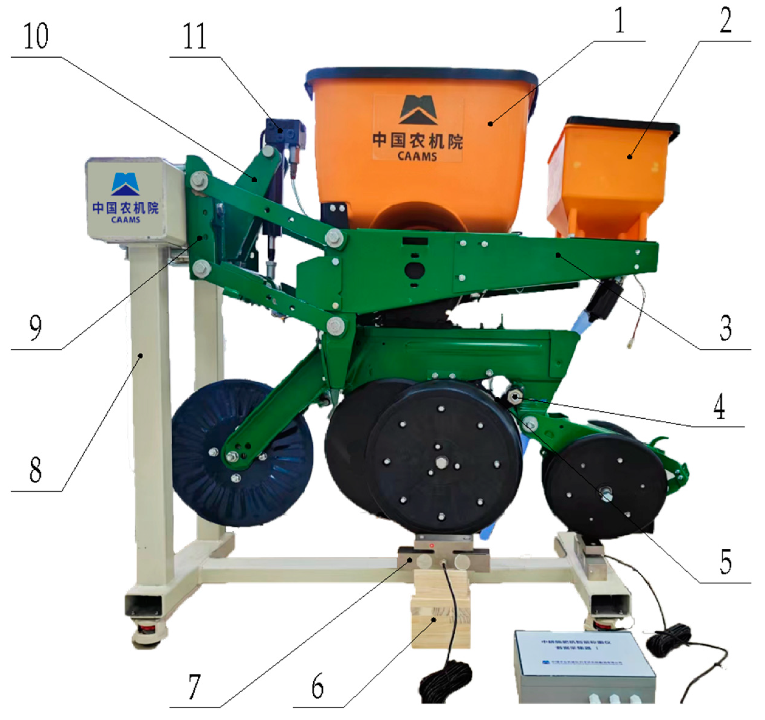
In order to approximate the target value more quickly when generating compressive force, combined with mechanical calculations, we have established the F-I relationship model between the input current of the IPRC and the downforce by field calibration. As shown in Figure 9, after suspending the row unit soil-contacting parts, the force of both sides of the gauge wheel on the ground was measured by using the self-researched intelligent weighing instrument, which is mounted on the gauge wheel support blocks. The input current range was 500~1400 mA (remove deadband), the step size was set to 50 and the number of steps was 18. The weighing instrument readings were recorded and the data were imported into the MATLAB 2018 linear fitting tool, and the relationship between the input current value y of the IPRC and the downforce x was obtained as
y = 1.231 x 614.666   ( 500     x     1400 )  
where y is the measured downforce value, N; and x is the input current value of the pressure-reducing valve, mA.
Take the amount of change of the x, y values of Equation (14), respectively, and transform as
Δ x = 0.8123 × Δ y
After the validation test of the model, Equation (15) was used as the F-I model for the relationship between the current and downforce. This model is used for the feedforward adjustment of the sowing depth control. When the difference in the downforce is measured, the output current can be adjusted according to the F-I model and superimposed with the output of the PID, which is able to reach the target downforce quickly in complex operating conditions.
(c)
Sowing Depth System Control Flow Design
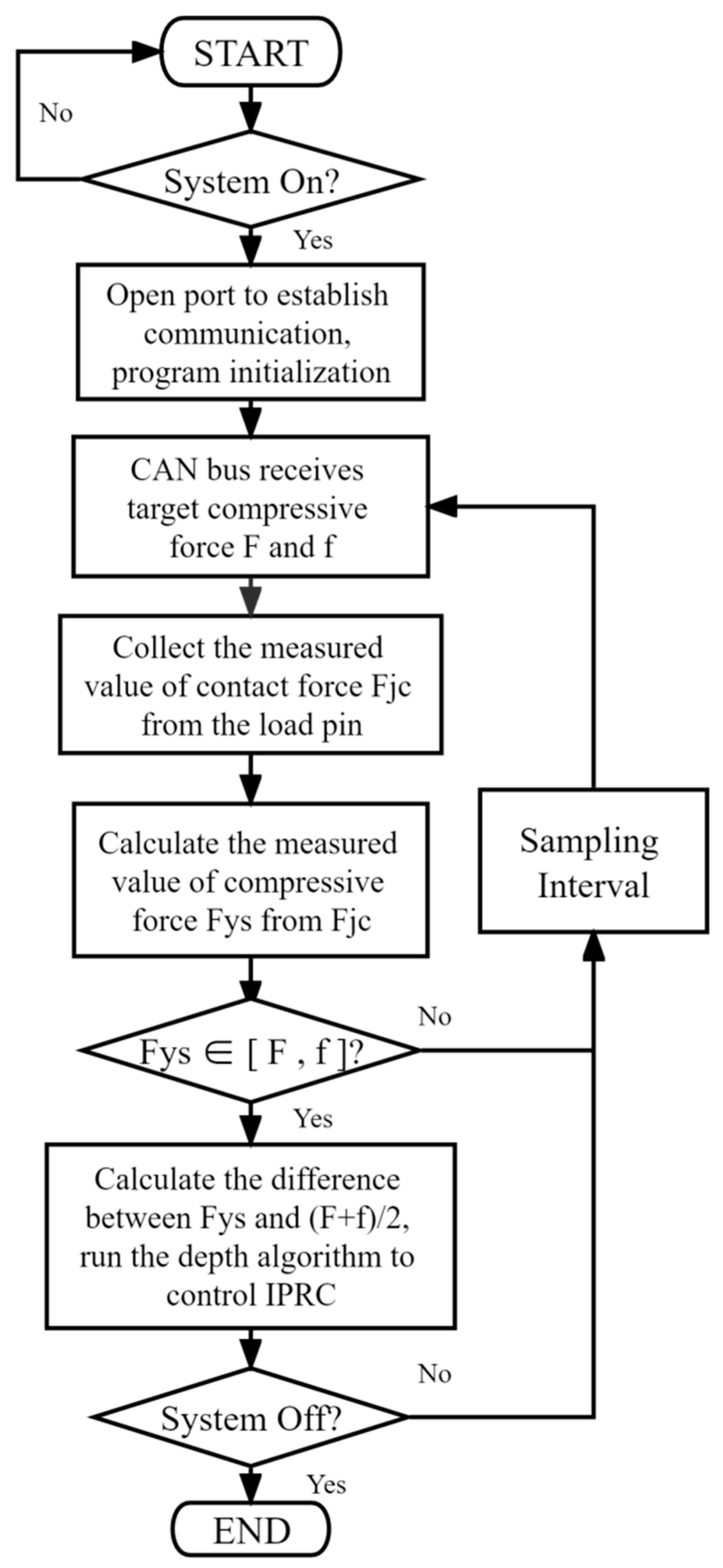
The system compares the actual value of the load pin with the target value of the compaction by collecting the load pin, and then calculates the difference by the control unit, outputs the incremental current according to the F-I model and runs the PID depth algorithm to achieve the target compaction force. All the control steps are shown in Figure 10.
(1)
The program opens the serial port to establish communication and starts initializing each operating parameter when it detects that the system is on;
(2)
The control unit receives the target value of the compaction force Ftarg range [F, f] set by the user on the display through the CAN communication program. By default, the depth control system gives three different compaction levels of “low, medium and high” for different crops. To avoid frequent starting and stopping of the IPRC, the default value range of Ftarg is ±500 N and the CAN communication flag bit is used to determine whether the data are received successfully. FtargT is the average of F and f;
(3)
Collect the analog output signal of the load pin, read the measured contact force actual value FJC, use the first-order low-pass filtering method to process the sensor data, and then replace it by the model for the measured compaction force FYS and send the data to the CAN bus and display it on the screen;
(4)
The system judges whether the FYS measurement is within the regulation range. If not, the system cycle re-monitors after delaying one sampling interval; if yes, the difference ∆F between the FYS measurement and Ftarg is calculated, and the input current of the IPRC is adjusted according to the F-I model. Afterward, the downforce is driven to the target value by a PID closed-loop control algorithm with feedforward compensation;
(5)
Judge whether the system is closed. If yes, end the monitoring cycle; if no, delay the sampling interval and return to the starting point of the cycle.
(d)
HMI Development
The system’s upper computer uses the SPD-070-Ax, a 7-inch display from Shobo Electronics, to communicate with the control unit through the RS-485 serial port, with default communication parameters of baud rate 9600 b/s, 8-bit data and no checksum. The HMI design and programming are written in the same CODESYS V3.5 SP17 programming environment based on the creation of the HMI Project module. The debugging and downloading of the program are performed via Ethernet connection to the PC. The Ftarg for the on-screen parameter setting is sent to the PLC control unit via the CAN bus interface. The design of the HMI is shown in Figure 11, which mainly includes a communication switch, hydraulic switch and compression force range setting. In order to facilitate users to observe the system working condition, the real-time display of the current downforce FXY, the sidewall compaction force FYS and the downforce quality evaluation index are set at the bottom of the interface.
Among them, the sidewall compaction force setting range represents the triggering condition of the sowing depth system; the communication switch configures and initializes the parameters of each interface in the way that the control system turns on and off; the hydraulic switch controls the energization of the reversing valve of the main circuit; the current downforce can display the current downforce level of the single unit in real time, and its principle is the actual value of the downforce derived from the conversion of the feedback signal of the pressure-reducing valve; the sidewall compaction force made the monitoring value of the load pin be displayed in real time after filtering and calculating, and the data indicate the actual value of the comprehensive downforce of the gauge wheel on the soil; and the downforce quality index fluctuates and changes in real time with the operation, which reflects the evaluation index of the control effect of the downforce at that moment, and the downforce quality index W is calculated as follows:
W = n c N c × 100 %
where W is the downforce mass index, %; nc is the number of samples in the set compaction range; and Nc is the total number of samples per unit time of the compaction force.

2.5. Test Equipment and Methods

2.5.1. Experimental Arrangement

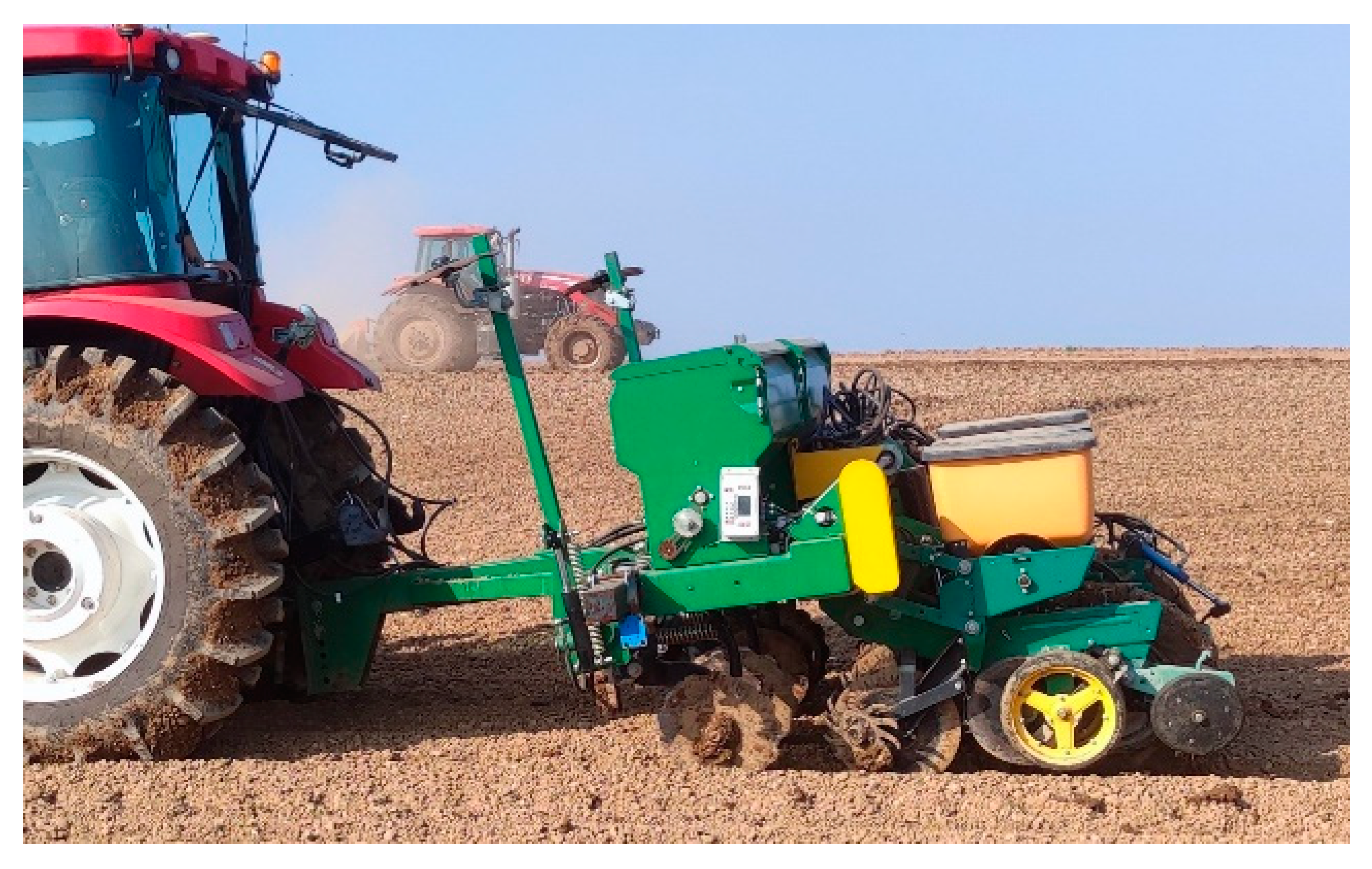
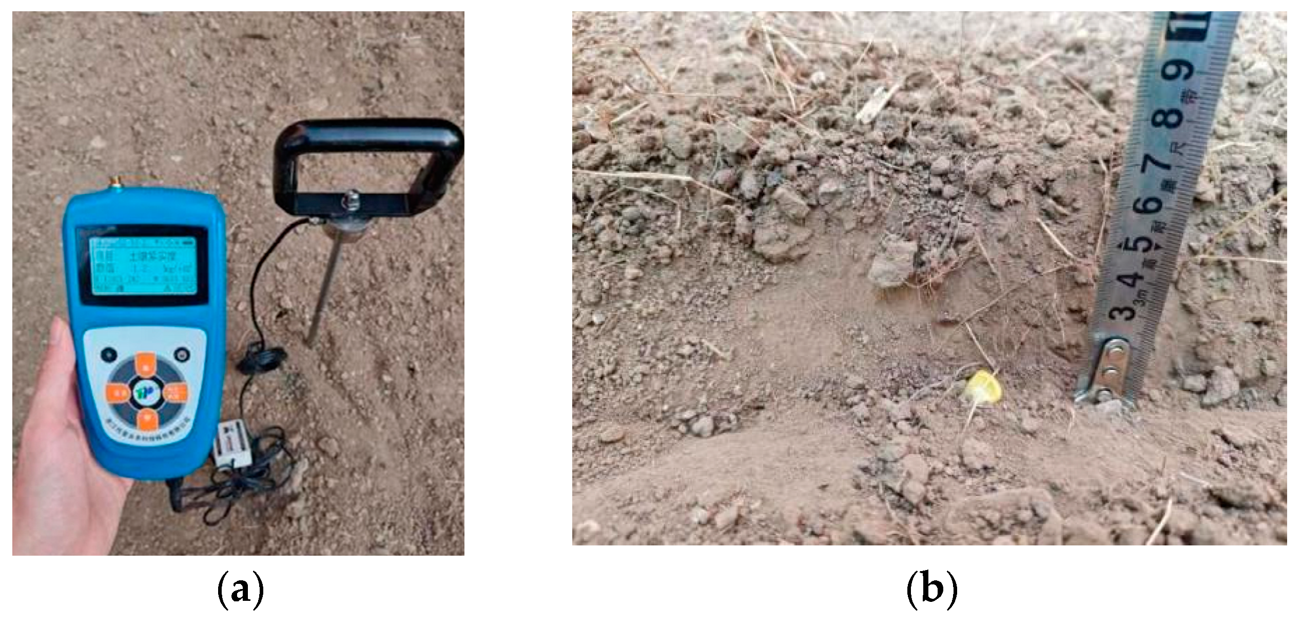
To test the effect of the sowing depth control of the system at different vehicle speeds and to compare the profiling performance of the mechanical adjustment and electro-hydraulic adjustment. The field test was conducted on November 10, 2022, in Hujiazhuang Township, Laishui County, Baoding City, Hebei Province, China. As shown in Figure 12, the test plot was no-till land, divided into an operating area of 150 m long and 25 m wide. The soil temperature of 5 cm below the surface of the test area was 10 °C and the relative humidity was 18.0% using the five-point sampling method (measured by RS-ECH-I20 temperature and humidity meter, Shandong Renke Measurement and Control Technology Co., Ltd., Jinan, China). The resolution of the measurement was 2.5 cm and 35 kPa (TJSD-750-IV soil compactness measuring instrument, Zhejiang Topunnong Technology Co., Hangzhou, China), as shown in Figure 13a. The test device was a 2BJ-470B corn no-till precision seeder (Hyundai Agricultural Equipment Technology Co., Ltd.) equipped with this paper’s sowing depth control system, with an overall mass of 1700 kg, a supporting power of 66.15 kW, an operating width of 2.8~3.2 m and a tractor traction connection, with a working row number of 4 and a row spacing of 0.7 m.
According to the agronomic requirements of the area, the sowing depth of all the row units was uniformly set to 50 mm by the sowing depth adjustment handle before the test, and the test plot was divided into three blocks in order to compare and test the sowing depth effect of different vehicle speeds. Three different speeds of 5~6 km·h−1, 7~8 km·h−1 and 9~10 km·h−1 were used for the test. In order to compare the effect of the sowing depth with different adjustment methods, No.1 and No.2 were set as the mechanical spring adjustment in two pretightened, No.3 as the self-weight adjustment and No.4 as the electro-hydraulic adjustment. Before the test, the target compressive force range was set to [200, 500] N through the display. A total of 4 × 1500 kg counterweights were added to the seed drill to ensure that the downforce can be applied properly.
In order to facilitate visual measurement data, the closing wheel assembly at the end of the row unit was removed, the furrow closing operation of the seeder was cancelled and only the furrowing opening test was conducted. In order to reduce the influence of tractor acceleration and deceleration on the test results when turning around the ground, points were selected in the middle area 25 m away from the ground edge, and one measurement point was selected every four theoretical seed distances. The sowing depth was measured as the vertical distance from the surface plane to the bare seed skin (Figure 13b). Each vehicle speed was divided into 3 areas of the front, middle and back, and each area measured 10 sowing depth data as a group to carry out 3 sets of sowing performance tests under different vehicle speeds. The soil compaction of the seed groove after sowing was also measured using a soil compactness measuring instrument. The compaction measurement method is measure and record the soil compaction data of 2.5 cm, 5 cm, 7.5 cm and 10 cm depth below the ground surface on both sides of the seeds.

2.5.2. Evaluation Indicators

According to the determination standard of the qualified sowing depth range (h ± 10) mm in the agricultural industry standard NY/T 1768-2009 [44], the qualified sowing depth range of this test is set to 40~60 mm, and the calculation formula of each index is as follows:
η 1 = n 1 N 1 × 100 %
h ¯ = h i N
S h = ( h i - h ¯ ) 2 N
V h = S h h × 100 %
where η1 is the qualified rate of the sowing depth, %; n1 is the number of the qualified sowing depth; N1 is the total number of the sowing depth measurement points; h ¯ is the mean value of the sowing depth, mm; hi is the sowing depth measurement value, mm; Sh is the standard deviation of the sowing depth, mm; and Vh is the variation coefficient of the sowing depth, %.
In addition, according to the control principle of the downforce and the sowing depth, the situation in which the sowing depth is qualified but the compaction of the seed groove is too high is likely to occur when the downforce is overloaded. Especially for the no-till, the compactness of the soil before sowing is much higher than the soil condition of the tilled land, and the compaction of the sidewall of the seed groove should be reduced as much as possible during the no-till sowing. In order to comprehensively measure the suitability of the sowing depth and sidewall compaction, combined with the qualified compaction test data of no-till land [45,46], this test set the “seed groove environmental qualification rate” (SFEQ), and the method to determine whether the groove environment is qualified is if the sowing depth of a measurement point is within the set sowing depth (h ± 10) m and the compaction data are within the interval of [c,(1 + 20%)c] of the post-sowing soil compactness. The point is judged as the “seed groove environmental qualification rate” (SFEQ). Where c is the pre-sowing soil compaction/kPa, obtained by measuring the soil compaction data below H (the set sowing depth) at the tire marks of the gauge wheel, and one measurement point corresponds to one pre-sowing soil compaction data.
The seed groove environmental qualification rate (SFEQ) is calculated by the following formula:
η 2 = n 2 N 2 × 100 %
where η2 is the seed groove environmental qualification rate (SFEQ), %; n2 is the number of the qualified seed groove environment; and N2 is the total number of measuring points of the seed groove environment.

3. Results and Discussion

3.1. Dynamic Response Test of the Control System

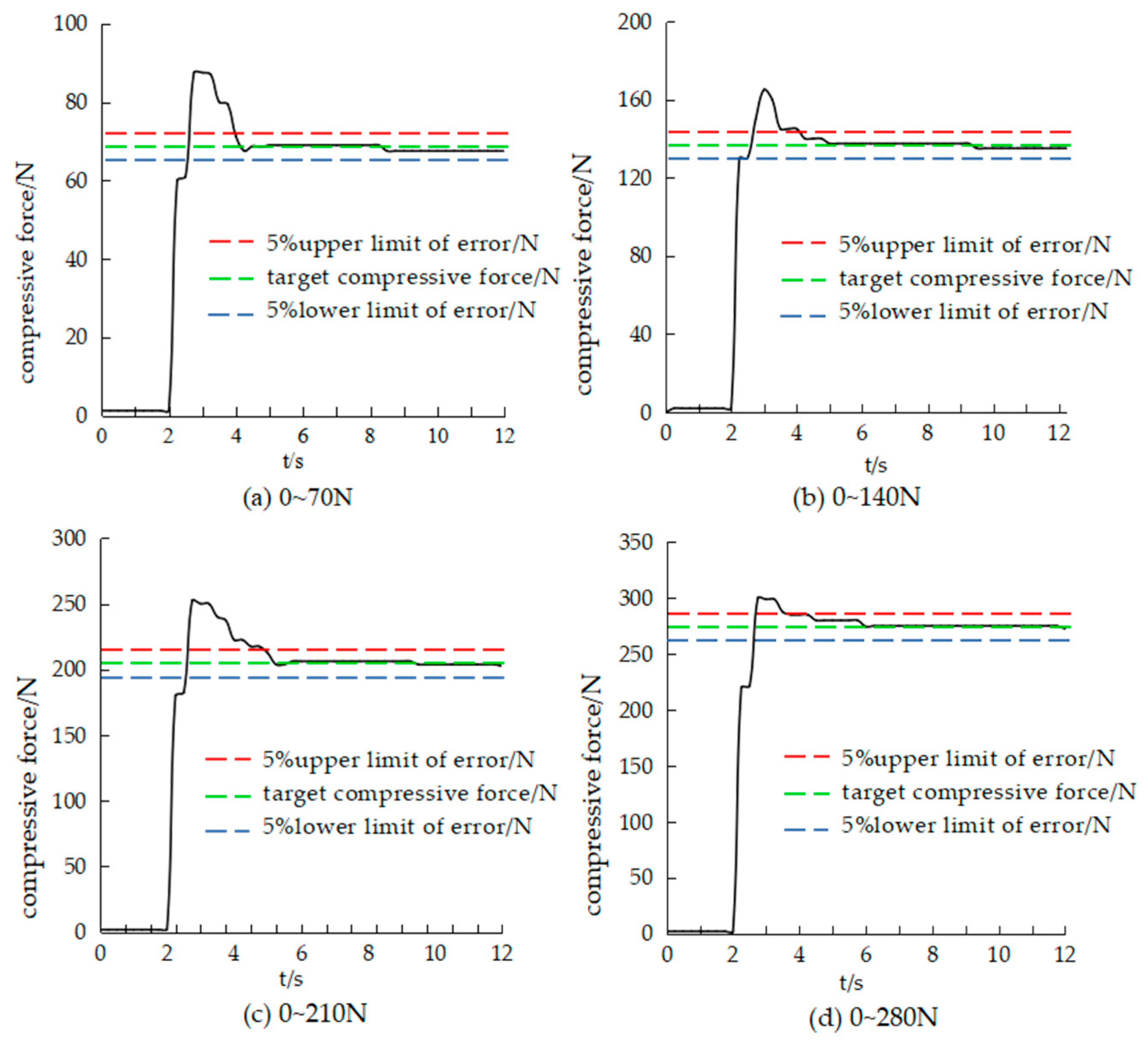
In order to evaluate the actual control effect of the sowing depth measurement and control system, we conducted dynamic tests on the IPRC in the field. The commonly used compaction setting value range of 0~280 N was selected, with a setting interval of 70 N. Four compaction adjustment ranges were selected: 70 N, 140 N, 210 N and 280 N. The data sampling frequency was selected as 10 Hz, the sampling time was 15 s and the test results were obtained, as shown in Figure 14.
The test results show that when the target compressive force is in the range of 0~280 N, the steady-state error of the system response is less than 10. When the target compressive force is 280 N, the adjustment time and rise time are at a maximum, 6.1 s and 0.64 s, respectively. The overshoot range of the four tests is 18.7%~26.6%, and the average value is 21.8%. The range of the steady-state error is 6.2~10.7, the average value is 8.63 and the error is within 10% when the system is stable. Looking at the curve, it can be seen that the pressure at the end of the system response is slightly reduced, the natural leakage of the system pressure is caused and the introduction of feedback regulation not only eliminates the system static difference but also compensates for the hydraulic pressure leakage. The detailed test result data are shown in Table 1.
Compared with other studies on sowing depth control, we provide a more powerful and stable sowing depth measurement and control system for seeders with the help of a tractor hydraulic system. In response testing, for example, Bai Huijuan’s study [31] used a split hydraulic valve group design with common PID control. The response speed measured under a bench test was 2.69 s, steady-state error 91.5 N and overshoot 2.9%. In this paper, we chose to complete the dynamic response test in the field to be able to predict the actual effect of the control system intuitively. Under the field test, the overshoot was reduced by 25.9% on average, and the response accuracy was improved by 90.6%. This is due to the sowing depth measurement and control algorithm which can adjust itself according to the soil environment, so our system has higher response accuracy.

3.2. Analysis of Field Tests Results

3.2.1. Effect of Sowing Depth Control

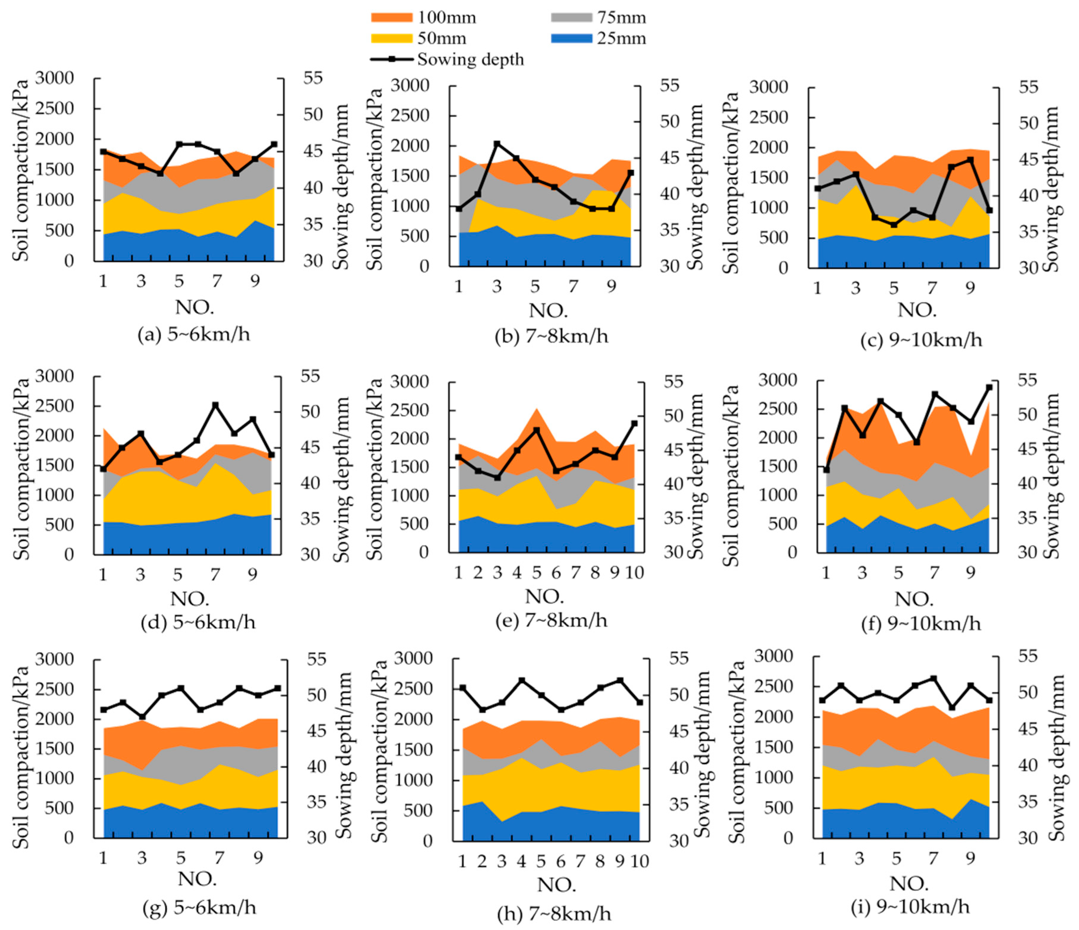
Figure 15 shows the sowing depth measurement data of three vehicle speed levels under three types of downforce regulation. In order to reduce the error, the mid-range measurement data of each vehicle speed were selected. The one with the best sowing depth was selected as the comparison data among the two sets of mechanical spring adjustment data. As shown in Figure 15, the black line is the sowing depth data, and the stacked area graph is the soil compaction data after sowing. Although the test machine has high profiling accuracy for homogeneous profiling, there will be profiling advance and lag due to the terrain, so a small amount of measured sowing depth data will slightly exceed the set sowing depth h.
By comparing the sowing depth data of three kinds of pressure adjustment methods, it can be seen that the sowing depth under electro-hydraulic adjustment is the closest to the set value on the whole, and the sowing depth stability from high to low is electro-hydraulic adjustment, mechanical spring adjustment and self-weight adjustment; by comparing three kinds of vehicle speed levels, it can be seen that with the increase in the operating speed, electro-hydraulic adjustment has the least influence on the sowing depth effect, mechanical adjustment is second and self-weight adjustment is the most influenced by vehicle speed.

3.2.2. Sidewall Compaction Force Control Effect

The compaction was measured at 50 mm (set sowing depth) on the sidewall of the seed groove using a soil compactness meter and the average value was taken. The experimental study found that the mean value of post-sowing soil compaction with electro-hydraulic adjustment was 1100 kPa, which was about 15.8% higher than the mean value of the pre-sowing no-till soil compaction of 950 kPa. The soil compaction under the self-weight adjustment state fluctuated the most due to the vibration of the row unit during operation, caused by the undulation of the ground surface. The peak soil compaction at a depth of 50 mm below the ground surface was 1000 kPa during 5~6 km·h−1 operation, while the peak compaction reached 1500 kPa during fast operation. Compared with the mechanical spring adjustment, the soil compaction degree of the electro-hydraulic adjustment is less affected by the vehicle speed and is more stable. Combined with the analysis of the sowing depth data, it can be found that the shallow sowing depth point is always accompanied by low soil compaction, which shows that the downforce of the row unit is not enough to meet the working pressure required by the coulter, resulting in the gauge wheel being suspended on the surface without pressure, thus causing the sowing depth to be too shallow. This is also consistent with the growth relationship in Figure 15 where the sowing depth is positively related to the compaction.
The total sowing depth measurement data of the front, middle and back sections were compiled and analyzed. The calculation results according to the index calculation method of Equations (17)–(20) are shown in Table 2. It can be seen that the error of the electro-hydraulic regulation in the average value of the sowing depth is the smallest, and the maximum error with the set value (50 mm) is only 0.73 mm, which appears at 9~10 km∙h−1. It can be seen from the qualified rate of the sowing depth that the self-weight regulation is influenced by the vehicle speed, while the mechanical regulation and electro-hydraulic regulation do not change much in value. The reason for the analysis is that the downforce provided when the row unit passes through some of the plots is overloaded, resulting in reaching the upper limit of the sowing depth while causing excessive soil compaction on the sidewalls of the seed groove. A further analysis of the standard deviation of the sowing depth showed that the standard deviation of the self-weight adjustment was 6.72 mm, which occurred at 7–8 km∙h−1. Combined with the analysis in Figure 15, this was due to the shallow sowing caused by the row unit’s inability to provide sufficient downforce when encountering hard plots, while the mechanical and electro-hydraulic adjustments reduced the coefficient of variation of the sowing depth by virtue of sufficient downforce and improved the sowing depth qualification rate.
In this section, the data of Bai huijuan’s study [31] show that the sowing depth qualification rates under electro-hydraulic control conditions are 88%, 82% and 78%. For the same electro-hydraulic-based sowing depth control, the integrated electro-hydraulic drive design has about 10% more of the qualification rate than the split design. In comparison, the coefficient of variation of the depth system using feedforward PID adjustment is reduced by about 53%. At a 5 cm depth setting, our integrated drive system has better suppression of vibration at high speed, which reduces the depth mismatch during high-speed operation.
The coefficient of variation of the sowing depth shows that the difference between the mechanical and electro-hydraulic regulation is not significant, which is presumed to be the reason that the mechanical group data are qualified in sowing depth but over-compacted due to the vibration bounce of the machine. For this reason, the seed groove environmental qualification rate (SFEQ) was established to further analyze the combined effect of the sowing depth and seed groove compaction.

3.2.3. Seed Groove Environmental Qualification Rate (SFEQ)

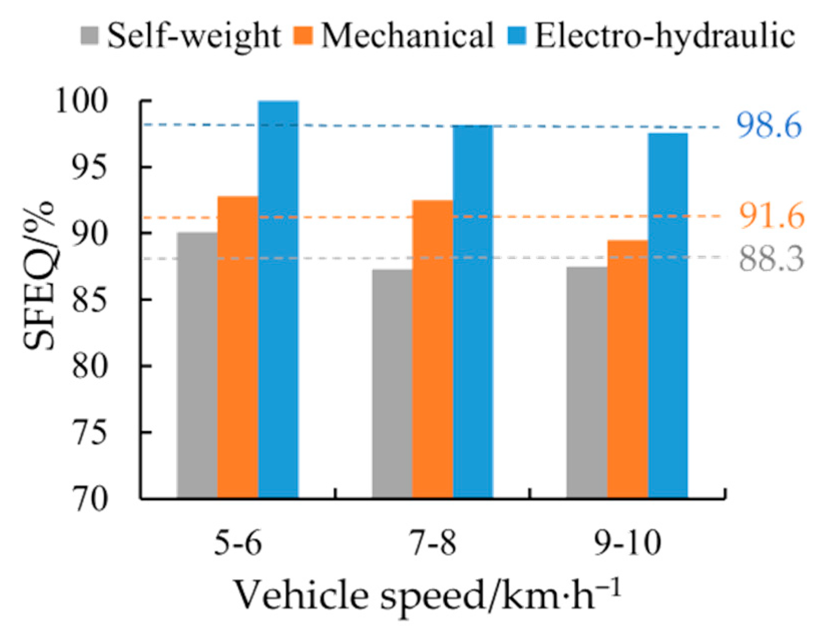
The seed groove environmental qualification rate (SFEQ) reflects the contact effect between the seeds and soil in the seed bed, including two important indexes of the sowing depth and seed groove compaction. According to the criteria for determining the qualified seed groove environment in Section 2.5.1, the data in Figure 15 were extracted and calculated to obtain a comparison chart of the SFEQ under three regulation methods, as shown in Figure 16.
It can be seen that there is a 7% mean difference between the mechanical and electro-hydraulic regulation in the SFEQ. Combining the two sowing depth qualification rates confirms that although mechanical regulation can achieve the ideal sowing depth, excessive downforce will inevitably cause excessive soil compaction. Comparing the pass rate of the self-weight-adjusted seed groove environment, it can be found that the self-weight downforce of the single unit cannot meet the downforce requirement of the no-till soil environment. In the case of setting the sowing depth of 50 mm, the best rate of the SFEQ of the electro-hydraulic regulation was 98.6% with the maximum error of 2.4, the mechanical regulation was 91.6% with the maximum error of 4.29, and the self-weight regulation was 88.3% with the maximum error of 2.8. It confirmed that the control of soil compaction by electro-hydraulic regulation was more stable and reliable than mechanical and self-weight regulation, which further demonstrated the importance of electro-hydraulic regulation in high-speed no-till operation. Electro-hydraulic regulation in high-speed no-till operation is superior.

4. Conclusions

In this paper, we analyzed the process of sowing depth control of a 470B row unit, optimized the profiling mechanism with the IPRC, developed the feedforward adjustment sowing depth control algorithm under the CODESYS environment and designed an integrated electro-hydraulic-driven sowing depth measurement and control system. It solves the problems of the complex structure of the profiling mechanism, improves the stability of the sowing depth and reduces the compaction of the sidewall of the seed groove. The main research conclusions are as follows.
(1)
The step response test results show that when the target compressive force is in the range of 0~280 N, the steady-state error of the system response is less than 10. When the target compressive force is 280 N, the adjustment time and rise time are at a maximum, 6.1 s and 0.64 s, respectively. The overshoot range of the four tests is 18.7%~26.6%, and the average value is 21.8%. The range of the steady-state error is 6.2~10.7, the average value is 8.63 and the error is within 10% when the system is stable.
(2)
The field performance test results show that under the condition that the sowing depth is set at 50 mm and the vehicle speed is 9~10 km∙h−1, the sowing depth qualification rates of the three adjustment methods of self-weight, mechanical and electro-hydraulic adjustment are 89.2%, 96.7% and 98.6%, respectively. The corresponding maximum sowing depth coefficients of variation are 16.7%, 12.9% and 6.4%, respectively. The SFEQ was further analyzed in combination with soil compaction, and the average pass rates under the three adjustment methods are 88.3%, 91.6% and 98.2%, respectively. The test confirms that suitable downforce can effectively reduce the effect of vehicle speed on sowing depth and soil compaction, while electro-hydraulic regulation can avoid over-compaction of seed groove soil while ensuring the sowing depth. It further shows the superiority of electro-hydraulic regulation in high-speed no-till operation and reflects the importance of seeding row unit downforce regulation in building a qualified seed groove environment.
(3)
Seed depth and soil compaction are an opposite problem; when we guarantee 100% seed depth, we necessarily give up some compaction issues. This paper for soil compaction tests only in the same plot, and the soil hardness variation range is small. The compaction effect of the seeder under different degrees of soil hardness was not examined. In the follow-up study, we will test the consistency of seedling emergence in a changing environment, such as different soil types and conditions, tillage practices, etc. In addition, the generally high pass rate of the sowing depth measured in this paper’s experiment is due to the good uniformity of the plots and the lack of a large sample size, and the need to define the criteria more strictly in subsequent experiments. Based on future test data, we aim to optimize the sowing depth measurement and control algorithm and gradually improve the performance of the multi-row seeder.

Author Contributions

Conceptualization, L.Z.; methodology, L.Z. and Y.M.; software, Y.M. and H.Z.; validation, H.Z. and K.N.; formal analysis, K.N. and B.Z.; investigation, B.Z.; resources, L.W.; data curation, L.W; writing—original draft preparation, S.B.; writing—review and editing, S.B.; visualization, Y.Z.; supervision, Y.Z.; project administration, W.Z.; funding acquisition, W.Z. All authors have read and agreed to the published version of the manuscript.

Funding

This work was mainly supported by the National Program on Key Basic Research Project of China (Grant No. 2022YFD2001502).

Data Availability Statement

Data are contained within the article. The data presented in this study can be requested from the authors.

Conflicts of Interest

The authors declare no conflict of interest.

References

  1. Hong, Y. Design of Electronic Control System for Air-Absorbing Plot Seeder Plant Spacing. Ph.D. Thesis, Nanjing University of Information Science and Technology, Nanjing, China, 2021. (In Chinese with English Abstract). [Google Scholar]
  2. Lin, P. Experiment and Analysis of Precisionmetering Device for Rapeseed and Sesame. Ph.D. Thesis, Huazhong Agricultural University, Wuhan, China, 2021. (In Chinese with English Abstract). [Google Scholar]
  3. Liu, M.H. Exploration of Appropriate Groundwater Depth for Water Saving, Salt Suppression and Optimization of Maize Irrigation Schedule in the Hetao Irrigation District. Ph.D. Thesis, Inner Mongolia Agricultural University, Huhehaote, China, 2021. (In Chinese with English Abstract). [Google Scholar]
  4. Wang, M.J. Study on the Effect of Sowing Depth on Grain Yield and Growth Development of High-yield Maize in Xinjiang. Ph.D. Thesis, Shihezi University, Shihezi, China, 2020. (In Chinese with English Abstract). [Google Scholar]
  5. Liu, X.L.; Lin, H.B.; Li, Y.M.; Gong, L.; Miao, Z.H. Analysis on status and development trend on intelligent control technology for agricultural equipment. Trans. Chin. Soc. Agric. Mach. 2020, 51, 1–18. [Google Scholar]
  6. Xiao, J. Discussion on the application of maize precision sowing technology. Seed Technol. 2020, 38, 41–42. [Google Scholar]
  7. Bai, H.C.; Yi, S.J.; Feng, S.H. Development status and prospect of maize precision sowing technology. China South. Agric. Mach. 2021, 52, 74–75. [Google Scholar]
  8. Wang, L.L.; Liang, X.X.; Hu, X.L.; Fan, X.Q.; Zhao, B.; Zhou, L.M. Research progress on measurement and control technology for pneumatic seeder. J. Chin. Agric. Mech. 2021, 42, 15–24. [Google Scholar]
  9. Badua, S.A.; Sharda, A.; Strasser, R.; Ciampitti, I. Ground speed and seeder downforce influence on corn seed spacing and depth. Precis. Agric. 2021, 22, 1154–1170. [Google Scholar] [CrossRef]
  10. Virk, S.S.; Porter, W.M.; Li, C.; Rains, G.C.; Snider, J.L.; Whitaker, J.R. On-farm evaluation of seeder downforce in varying soil textures within grower fields. Precis. Agric. 2021, 22, 777–799. [Google Scholar] [CrossRef]
  11. Conway, L.S. Utilizing Commercial Soil Sensing Technology for Agronomic Decisions. Ph.D. Thesis, University of Missouri-Columbia, Columbia, MO, USA, 2022. [Google Scholar]
  12. Shi, D.J.; Yan, F.Y.; Fan, J.Z.; Zhong, C.S.; Lyu, J.Z. Effects of different sowing depths on seedling characters and yield of maize under no-tillage conditions. Hunan Agric. Sci. 2014, 2014, 19–21. [Google Scholar]
  13. The Keys to Consistent Emergence. Available online: https://www.precisionsowing.com/agronomy/research/the-keys-toconsistent-emergence (accessed on 20 January 2022).
  14. Virk, S.S.; Fulton, J.P.; Porter, W.M.; Pate, G.L. Row-crop seeder performance to support variable-rate seeding of maize. Precis Agric. 2020, 21, 603–619. [Google Scholar] [CrossRef]
  15. Zhao, H.H.; Zhang, D.X.; Yang, L.; Cui, T.; He, X.T.; Xie, C.T.; Du, Z.H.; Qin, Y.; Dong, J.Q.; Liu, W.T. Study on Measurement Method and Control Model for the Seeding Downforce of Seeding Unit Based on Bilateral Depth Limiting. Available at SSRN 4061460. Available online: https://www.semanticscholar.org/paper/Study-on-Measurement-Method-and-Control-Model-for-Zhao-Zhang/898814b92227bfea4281ae0edb18cf7af681fb98 (accessed on 29 April 2023).
  16. Saif, M. 7 difference between hydraulics and pneumatic. Eng. Post 2022, 1, 20. [Google Scholar]
  17. Cheng, X.; Zhou, J.; Zhang, W.Z.; Wang, Q.; Yu, H.F.; Zi, D.Y. Exploration of hydraulic and pneumatic transmission development. Hubei Agricultural. Mech. 2021, 2, 112–113. [Google Scholar]
  18. Karayel, D.; Özmerzi, A. Evaluation of three depth-control components on seed placement accuracy and emergence for a precision seeder. Appl. Eng. Agric. 2008, 24, 271–276. [Google Scholar] [CrossRef]
  19. Poncet, A.M.; Fulton, J.P.; McDonald, T.P. Effect of heterogeneous field conditions on corn seeding depth accuracy and uniformity. Appl. Eng. Agric. 2018, 34, 819–830. [Google Scholar] [CrossRef]
  20. Marchant, B.P. Time-frequency analysis for biosystems engineering. Biosyst. Eng. 2003, 85, 261–281. [Google Scholar] [CrossRef]
  21. Gao, Y.Y.; Wang, X.; Yang, S.; Zhai, C.Y.; Zhao, X.G.; Zhao, C.J. Development of CAN-based sowing depth monitoring and evaluation system. Chin. Soc. Agric. Mach. 2019, 50, 23–32. [Google Scholar]
  22. Papoutsidakis, M.; Chatzopoulos, A.; Papachristos, D.; Drosos, C. Hydraulics and pneumatics: Operational characteristics and control for modern industry applications. Int. J. Comput. Appl. 2019, 178, 31–40. [Google Scholar] [CrossRef]
  23. Wang, C.L.; Li, H.W.; He, J.; Wang, Q.J.; Lu, C.Y.; Chen, L.P. State-of-the-Art and Prospect of Automatic Navigation and Measurement Techniques Application in Conservation Tillage. Smart Agric. 2020, 2, 41–55. [Google Scholar]
  24. Nielsen, S.K.; Nörremark, M.; Green, O. Sensor and control for consistent seed drill coulter depth. Comput. Electron. Agric. 2016, 127, 690–698. [Google Scholar] [CrossRef]
  25. Nielsen, S.K.; Munkholm, L.J.; Lamandҫ, M. Seed drill instrumentation for spatial coulter depth measurements. Comput. Electron. Agric. 2017, 141, 207–214. [Google Scholar] [CrossRef]
  26. Nielsen, S.K.; Munkholm, L.J.; Lamandҫ, M. Seed drill depth control system for precision seeding. Comput. Electron. Agric. 2018, 144, 174–180. [Google Scholar] [CrossRef]
  27. Fu, W.Q. Study on Key Technology of Quality Control for Maize No-tillage Drilling Machinery. Ph.D. Thesis, China Agricultural University, Beijing, China, 2018. [Google Scholar]
  28. Wen, L.; Fan, X.; Liu, Z. The design and development of the precision seeder sowing depth control system. Sens. Transducers 2014, 162, 53–58. [Google Scholar]
  29. Suomi, P.; Oksanen, T. Automatic working depth control for seed drill using ISO 11783 remote control messages. Comput. Electron. Agric. 2015, 116, 30–35. [Google Scholar] [CrossRef]
  30. Weatherly, E.T.; Bowers, C.G. Automatic depth control of a seed seeder based on soil drying front sensing. Trans. ASAE 1997, 40, 295–305. [Google Scholar] [CrossRef]
  31. Bai, H.J.; Fang, X.F.; Wang, D.C.; Yuan, Y.W.; Zhou, L.M.; Niu, K. Design and Test of Control System for Seeding Depth and Compaction of Corn Precision seeder. Chin. Soc. Agric. Mach. 2020, 51, 61–72. [Google Scholar]
  32. Ag Leader Technology. Hydraulic Down Force Installation Incompatibilities. Available online: https://www.agleader.com (accessed on 8 February 2022).
  33. Ag Leader Technology. ISOBUS Hydraulic Down Force Row Module Detection. Available online: https://www.agleader.com (accessed on 8 February 2022).
  34. Dawn Equipment Company. Rfx Hydraulic Seeder Row Unit Down-Pressure. Available online: http://www.Dawnequipment.com/Dawn_Reflex.html (accessed on 19 December 2022).
  35. Deere & Company. Seeder Parts. Depth Control. John Deere US. Available online: https://www.deere.com/en_US/parts/parts_by_industry/ag/seeding/depth-control/depth-control.page (accessed on 19 December 2021).
  36. Precision Sowing LLC. Deltaforce System Operation. Available online: https//www.precisionsowing.com (accessed on 19 December 2022).
  37. Precision Sowing Inc.20/20 Airforce Owner’s Manualsion. Available online: https://support.precisionsowing.com/pubs/?file=0BwSYzyFHvNvUdUJPdjlRdWlIWjA (accessed on 12 January 2023).
  38. Kinze. Retrofit Kits. Available online: https://www.kinze.com/owners/retrofit-kits (accessed on 12 January 2023).
  39. Ma, H.Y.; Wang, W.B.; Wang, K.; Zhai, Q.Z.; Guo, D.Q. Parallel four-bar profiling mechanism design and motion simulation. Mech. Eng. 2014, 7, 121–123. [Google Scholar]
  40. Geng, X.Q. Research on Precision Hydraulic Sowing Machine Unit Depth Control. Master’s Thesis, Northeastern University, Shengyang, China, 2017. [Google Scholar]
  41. The Ohio State University. Seeder Downforce Information. Available online: https://digitalag.osu.edu/precision-ag/research-focuses/precision-seeding (accessed on 20 January 2023).
  42. Tang, Y.D. Handbook of Hydraulic Cylinder; China Machine Press: Beijing, China, 2021; pp. 117–125. [Google Scholar]
  43. Yang, F.; Gao, S.Q. Introduction to the development history and trends of microcontrollers. Technol. Pioneers 2013, 14, 9–59. [Google Scholar]
  44. NY/T 1768-2009; Technical Specifications of Quality Evaluation for No-Tillage Drilling Machinery. Agricultural Industry Standards of the People’s Republic of China: Beijing, China, 2009.
  45. Zhang, R. Study on Precision Depth-Control Mechanism of Corn No-Till Seeder in Double-Cropping Area. Ph.D. Thesis, China Agricultural University, Beijing, China, 2016. [Google Scholar]
  46. Jing, H.R.; Zhang, D.X.; Wang, Y.X.; Yang, L.; Fan, C.L.; Zhao, H.H.; Wu, H.L. Development and performance evaluation of an electro-hydraulic downforce control system for seeder row unit. Comput. Electron. Agric. 2020, 172, 105073. [Google Scholar] [CrossRef]
Figure 1. Row unit force diagram: (1) integrated pressure-reducing cylinder (IPRC), (2) four-bar linkage, (3) seed box, (4) closing wheel, (5) sowing depth adjustment mechanism, (6) state II position of gauge wheel, (7) state I position of gauge wheel, (8) double-disc coulter, (9) ripple disc.
Applsci 13 05823 g001
Figure 2. Schematic diagram of the sowing depth measurement and control system: (1) integrated pressure reducing cylinder (IPRC), (2) pressure-reducing relief valve, (3) hydraulic cylinder, (4) load sensor, (5) angle sensor, (6) sensor unit, (7) hydraulic quick coupling, (8) throttle speed control valve, (9) check valve, (10) main pressure-reducing valve, (11) main valve set.
Applsci 13 05823 g002
Figure 3. Schematic diagram of profiling range of profiling mechanism.
Applsci 13 05823 g003
Figure 4. Schematic diagram of the upper and lower limits of the four-bar linkage: (1) integrated pressure-reducing cylinder (IPRC), (2) upper rod, (3) limit plate, (4) lower rod, (5) spring tie rod, (6) cylinder pressure plate, (7) top plate, (8) cylinder bracket.
Applsci 13 05823 g004
Figure 5. Diagram of the force of the sowing depth adjustment mechanism: (1) sowing depth adjustment handle, (2) frame, (3) gauge wheel arm, (4) depth-limiting block, (5) axle pin sensing, (6) axle pin fixing support, (7) depth-limiting stopper.
Applsci 13 05823 g005
Figure 6. (a) Diagram of the IPRC, (b) IPRC schematic: (1) valve block, (2) return pipe, (3) piston rod, (4) cylinder, (5) cartridge-type pressure-reducing valve.
Applsci 13 05823 g006
Figure 7. (a) Load pin, (b) tilt angle sensor.
Applsci 13 05823 g007
Figure 8. Closed-loop PID depth control system with feedforward compensation.
Applsci 13 05823 g008
Figure 9. Row unit bench test: (1) seed box, (2) fertilizer box, (3) frame, (4) load pin, (5) angle sensor, (6) gauge wheel support blocks, (7) weighing instrument, (8) test stand, (9) four-bar linkage, (10) cylinder bracket, (11) IPRC.
Applsci 13 05823 g009
Figure 10. Sowing depth control flow chart.
Applsci 13 05823 g010
Figure 11. System display interface design.
Applsci 13 05823 g011
Figure 12. Field tests.
Applsci 13 05823 g012
Figure 13. Field tests. (a) Soil compaction measurement; (b) sowing depth measurement.
Applsci 13 05823 g013
Figure 14. Step response test results of the depth system at different compressive force settings. (a) 0~70 N; (b) 0~140 N; (c) 0~210 N; (d) 0~280 N.
Applsci 13 05823 g014
Figure 15. Sowing depth and compaction data of three adjustment methods at different vehicle speeds: (ac) self-weight adjustment; (df) mechanical adjustment; (gi) electro-hydraulic adjustment.
Applsci 13 05823 g015
Figure 16. The seed groove environmental qualification rate (SFEQ).
Applsci 13 05823 g016
Table 1. Sowing depth system dynamic test results.
NumberTarget Compressive Force/NSteady-State Value/NPeak/NOvershoot/%Steady-State Error/NAdjustment Time/s
17073.188.10 20.52 3.13.9
2140144.25164.83 14.26 4.255.2
3210204.18252.13 23.48 5.825.7
4280272.83299.28 9.69 7.176.1
avg 16.99 8.635.23
Table 2. Field test results of sowing depth control.
Plotting ParametersAdjust Method Vehicle Speed
/(km∙h−1)
5~67~89~10
Average sowing depth/mmSelf-weight44.3942.1841.20
Mechanical49.5246.8745.03
Electro-hydraulic49.6349.4049.27
Sowing depth qualification rate/%Self-weight95.8194.8389.21
Mechanical98.5498.2396.72
Electro-hydraulic100.00100.0098.62
Standard deviation of sowing depth/mmSelf-weight5.236.726.91
Mechanical3.265.135.83
Electro-hydraulic3.802.973.17
Coefficient of variation of sowing depth/%Self-weight11.7815.9316.77
Mechanical6.5810.9512.95
Electro-hydraulic7.666.016.43
Disclaimer/Publisher’s Note: The statements, opinions and data contained in all publications are solely those of the individual author(s) and contributor(s) and not of MDPI and/or the editor(s). MDPI and/or the editor(s) disclaim responsibility for any injury to people or property resulting from any ideas, methods, instructions or products referred to in the content.