
A Weakly-Coupled Double Bow-Tie Multi-Ring Elliptical Core Multi-Mode Fiber for Mode Division Multiplexing across C+L+U Band

Abstract
:1. Introduction
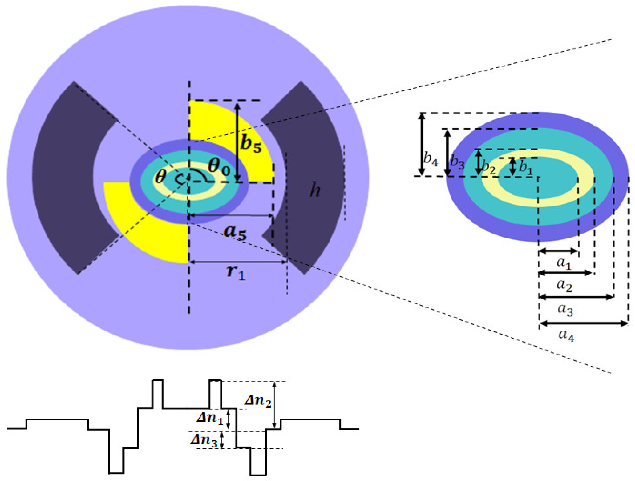
2. Fiber Design
3. Results Simulation Analysis and Optimization
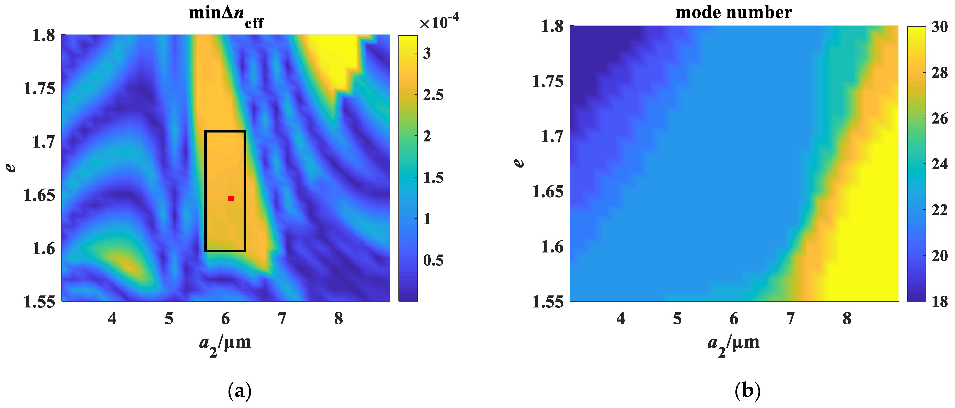
3.1. Optimization of Multi-Ring Elliptical Core Parameters
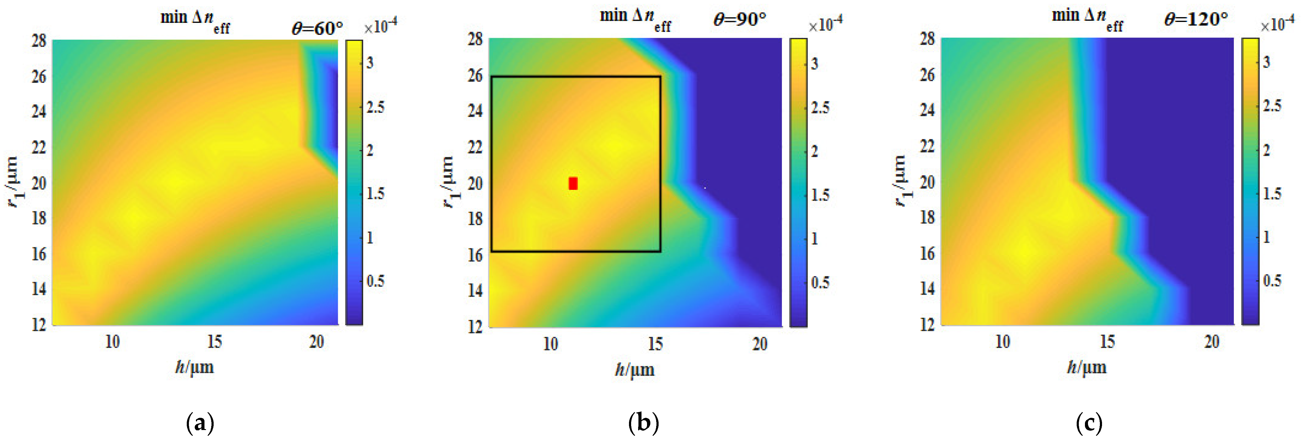
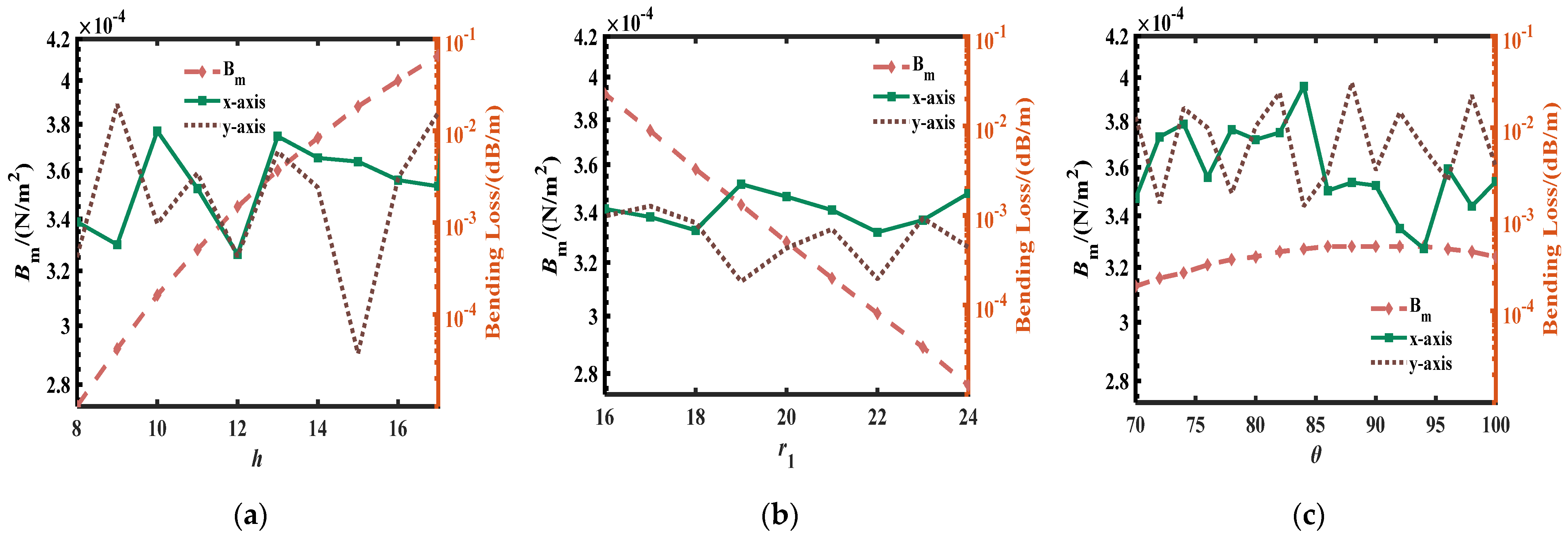
3.2. Optimization of Stress-Applying Parameters
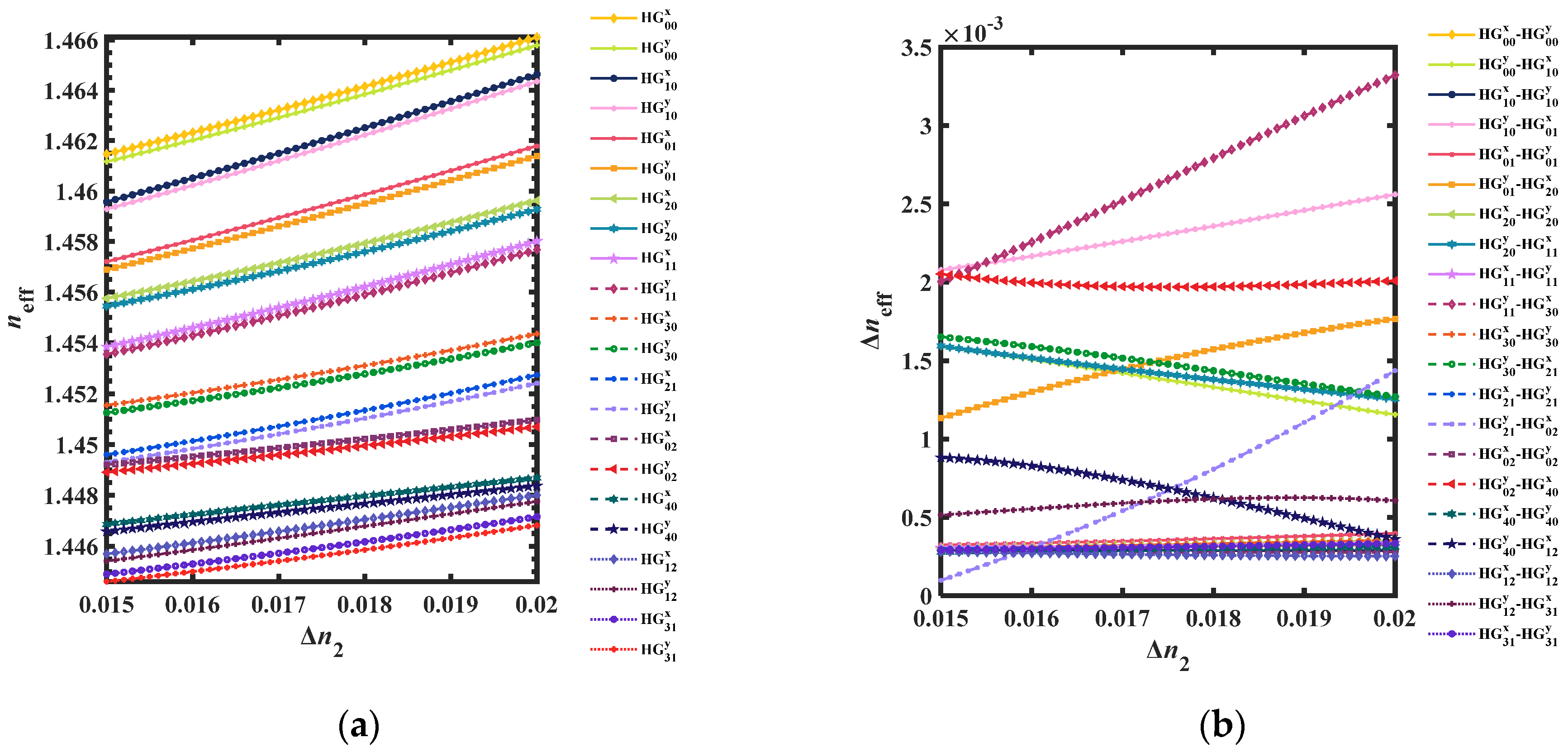
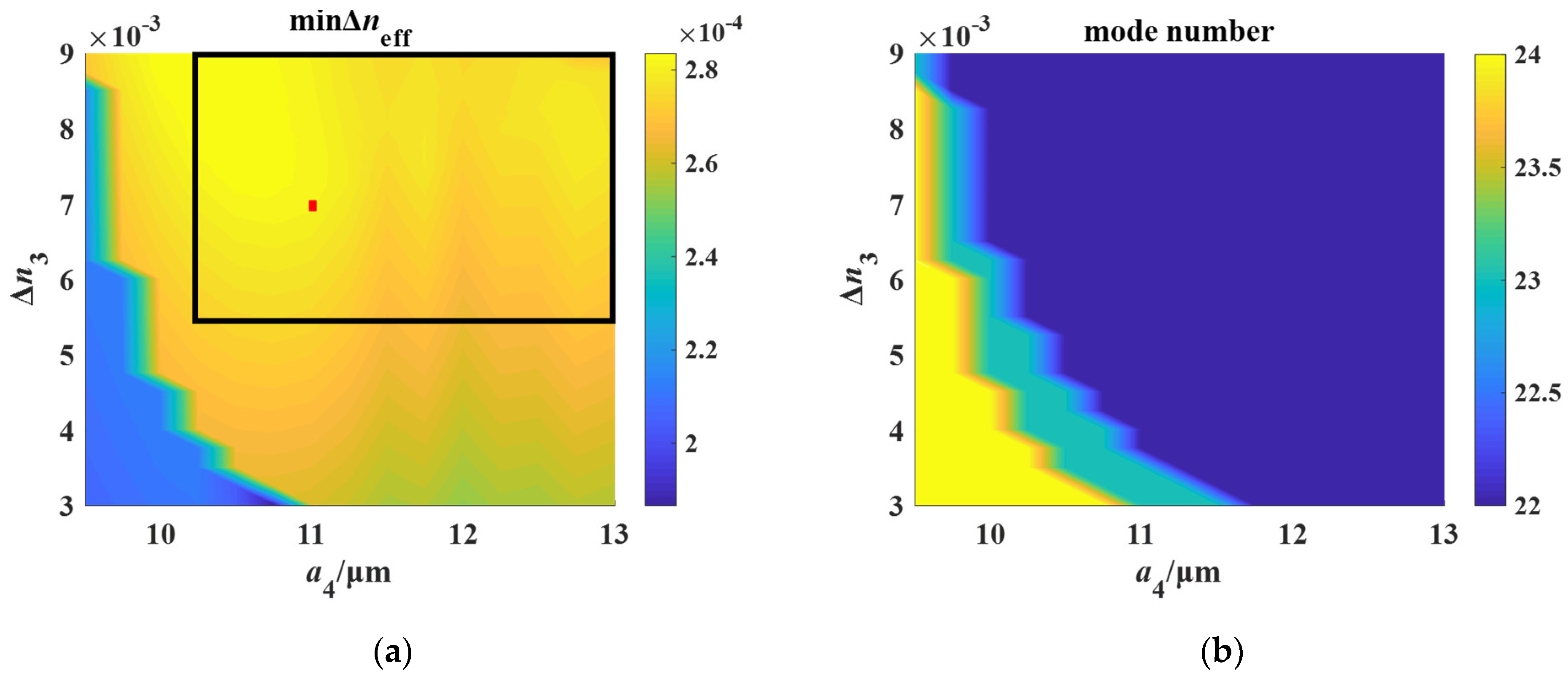
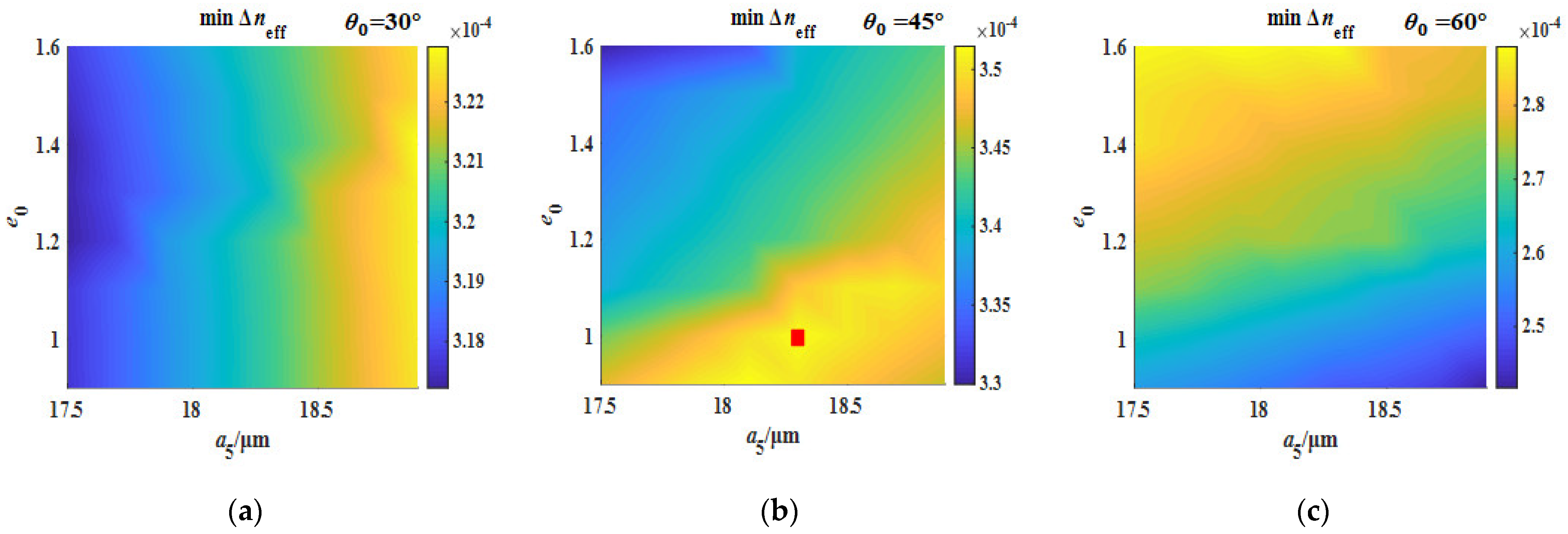
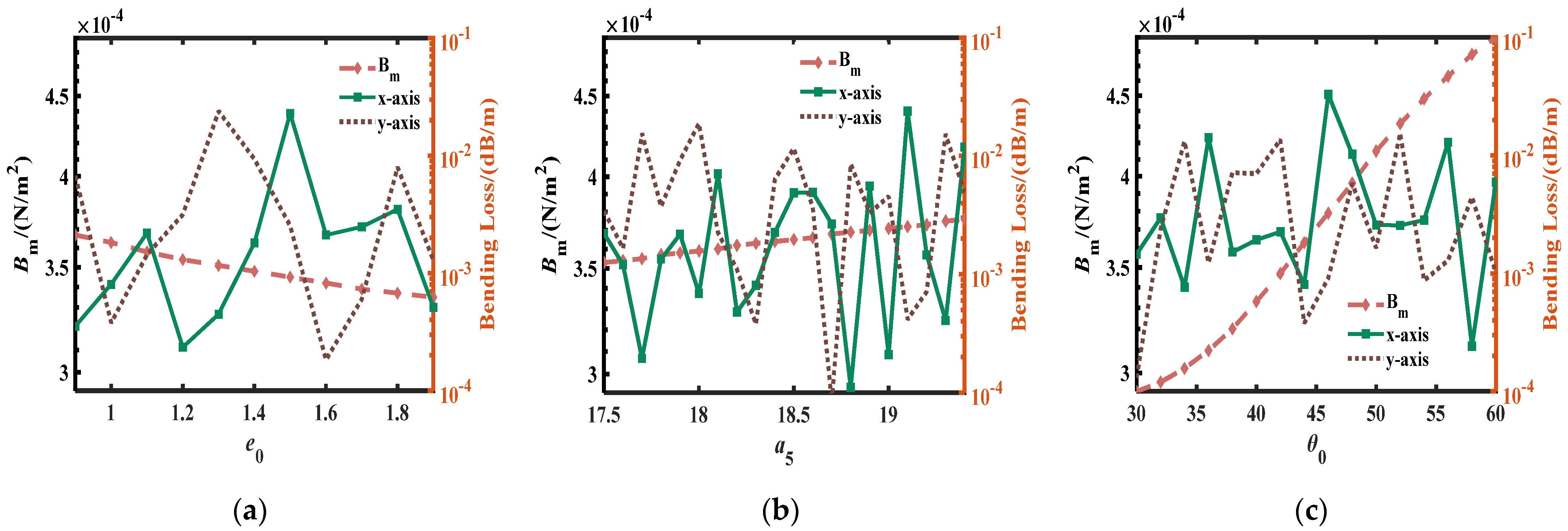
3.3. Optimization of Bow-Tie Air Holes Parameters
4. Mode Properties and Broadband Characteristics
4.1. Birefringence
4.2. Bending Loss
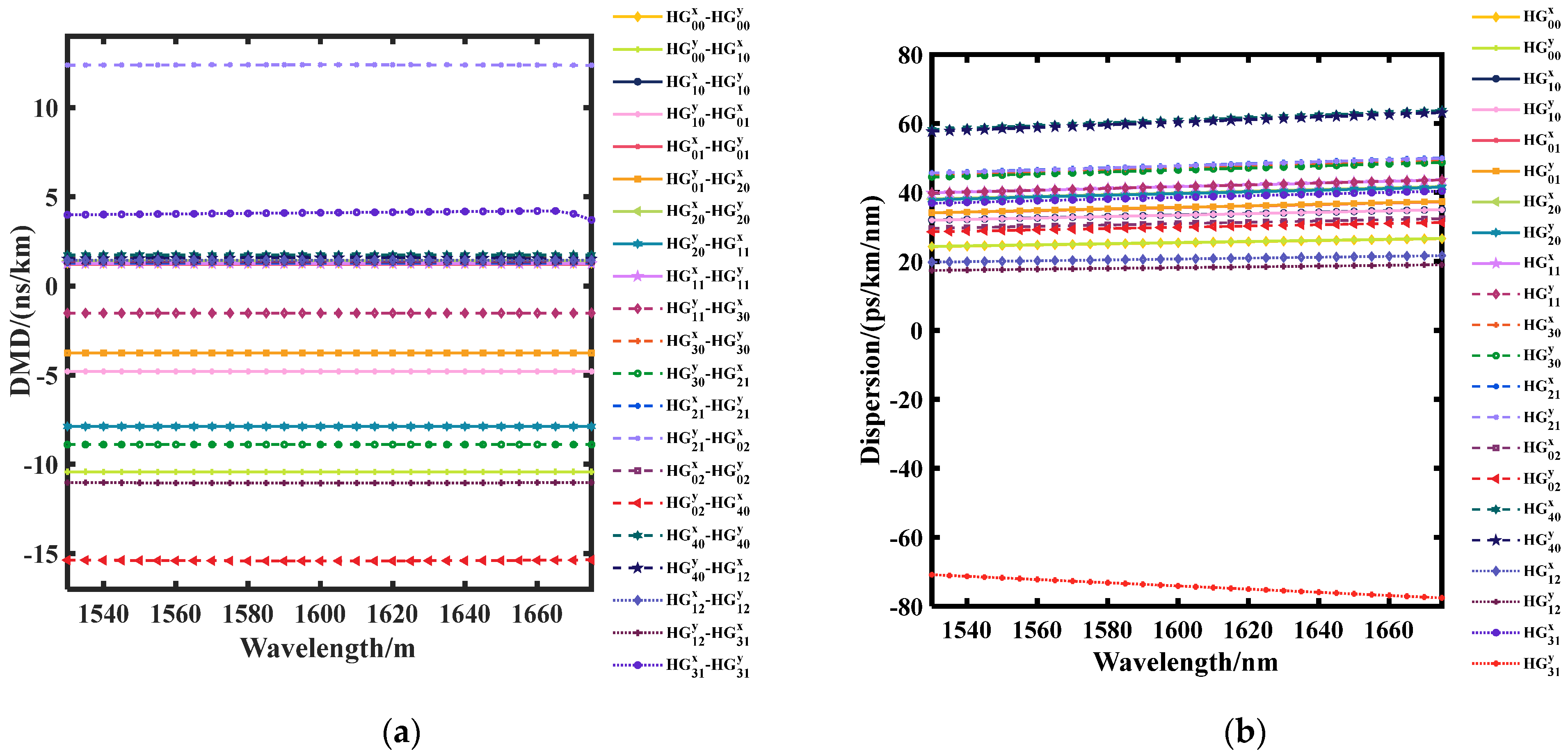
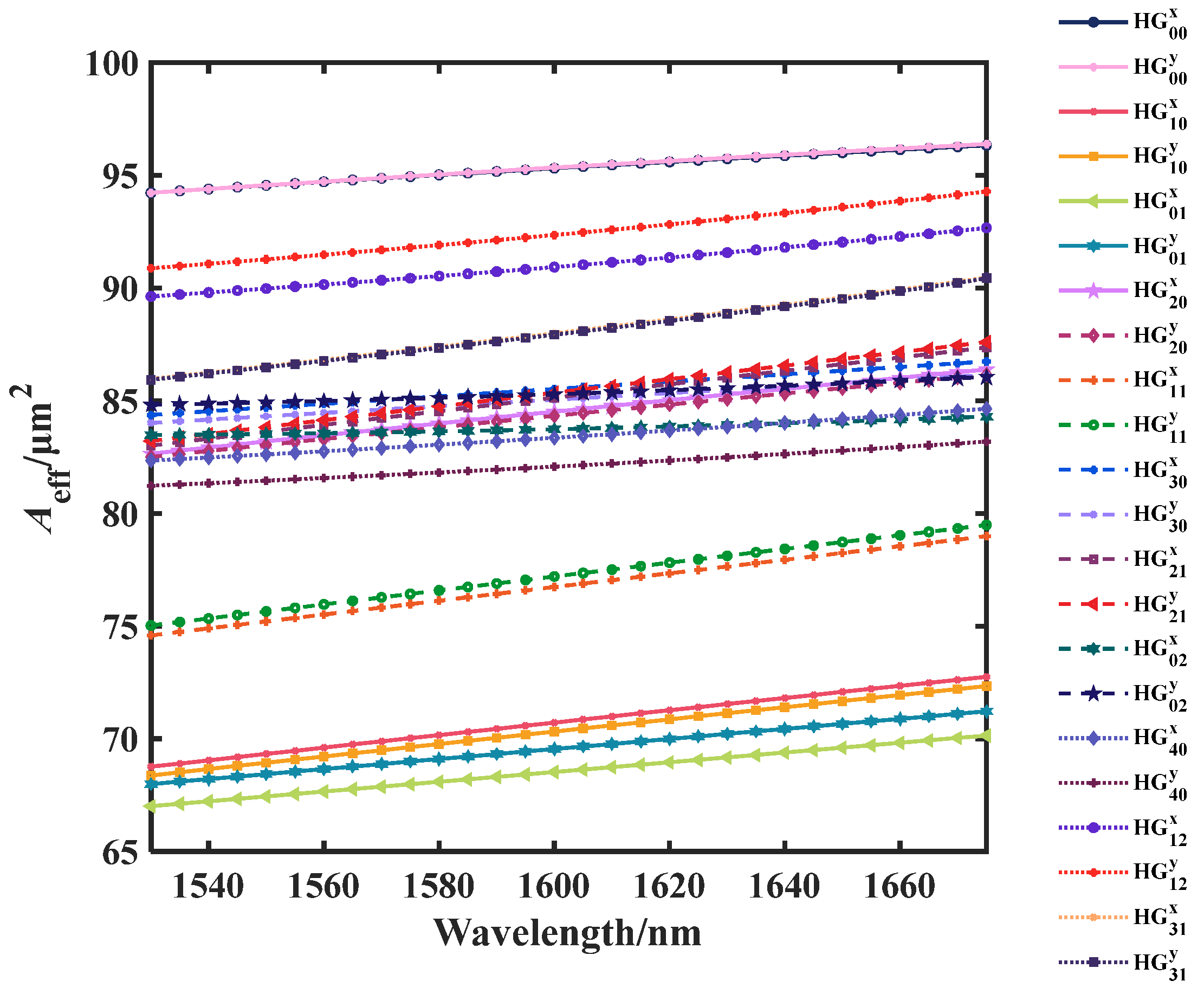
4.3. Broadband Performances
5. Fabrication Method and Tolerance
6. Conclusions
Author Contributions
Funding
Institutional Review Board Statement
Informed Consent Statement
Data Availability Statement
Conflicts of Interest
References
- Zhong, K.; Zhou, X.; Huo, J.; Yu, C.; Lu, C.; Lau, A.P.T. Digital Signal Processing for Short-Reach Optical Communications: A Review of Current Technologies and Future Trends. J. Light. Technol. 2018, 36, 377–400. [Google Scholar] [CrossRef]
- Gao, Y.; Li, Y.; Li, X.; Zheng, H.; Bai, C.; Hu, W.; Xu, H.; Dong, Q.; Xing, H.; Su, Y.; et al. An Elliptical-Core Few-Mode Fiber with Low Loss and Low Crosstalk for the MIMO-FREE Applications. Front. Phys. 2022, 9, 845. [Google Scholar] [CrossRef]
- Schares, L.; Lee, B.G.; Checconi, F.; Budd, R.; Rylyakov, A.; Dupuis, N.; Petrini, F.; Schow, C.L.; Fuentes, P.; Mattes, O.; et al. A Throughput-Optimized Optical Network for Data-Intensive Computing. IEEE Micro 2014, 34, 52–63. [Google Scholar] [CrossRef]
- Huang, M.-F.; Tanaka, A.; Ip, E.; Huang, Y.-K.; Qian, D.; Zhang, Y.; Zhang, S.; Ji, P.N.; Djordjevic, I.B.; Wang, T.; et al. Terabit/s Nyquist Superchannels in High Capacity Fiber Field Trials Using DP-16QAM and DP-8QAM Modulation Formats. J. Light. Technol. 2014, 32, 776–782. [Google Scholar] [CrossRef]
- Essiambre, R.-J.; Kramer, G.; Winzer, P.J.; Foschini, G.J.; Goebel, B. Capacity Limits of Optical Fiber Networks. J. Light. Technol. 2010, 28, 662–701. [Google Scholar] [CrossRef]
- Richardson, D.J.; Fini, J.M.; Nelson, L.E. Space-division multiplexing in optical fibres. Nat. Photonics 2013, 7, 354–362. [Google Scholar] [CrossRef]
- Yu, S. Potentials and challenges of using orbital angular momentum communications in optical interconnects. Opt. Express 2015, 23, 3075–3087. [Google Scholar] [CrossRef]
- Yang, Y.; Gao, J.; Fu, S.; Zhang, X.; Tang, M.; Tong, W.; Liu, D. PANDA Type Four-Core Fiber with the Efficient Use of Stress Rods. IEEE Photonics J. 2019, 11, 1–9. [Google Scholar] [CrossRef]
- Corsi, A.; Chang, J.H.; Wang, R.H.; Wang, L.X.; Rusch, L.A.; LaRochelle, S. Highly elliptical core fiber with stress-induced birefringence for mode multiplexing. Opt. Lett. 2020, 45, 2822–2825. [Google Scholar] [CrossRef]
- Wang, L.; Nejad, R.M.; Corsi, A.; Lin, J.; Messaddeq, Y.; Rusch, L.A.; LaRochelle, S. MIMO-Free transmission over six vector modes in a polarization maintaining elliptical ring core fiber. In Proceedings of the Optical Fiber Communication Conference and Exhibition, Los Angeles, CA, USA, 19–23 March 2017. [Google Scholar]
- Xia, C.; Bai, N.; Ozdur, I.; Zhou, X.; Li, G.F. Supermodes for optical transmission. Opt. Express 2011, 19, 16653–16664. [Google Scholar] [CrossRef]
- Arik, S.O.; Kahn, J.M.; Ho, K.-P. MIMO Signal Processing for Mode-Division Multiplexing: An Overview of Channel Models and Signal Processing Architectures. IEEE Signal Process. Mag. 2014, 31, 25–34. [Google Scholar] [CrossRef]
- Wang, L.; Nejad, R.M.; Corsi, A.; Lin, J.; Larochelle, S. Linearly polarized vector modes: Enabling mimo-free mode-division multiplexing. Opt. Exp. 2017, 25, 11736–11749. [Google Scholar] [CrossRef]
- Chen, S.; Tong, Y.; Tian, H.P. Eight-mode ring-core few-mode fiber using cross-arranged different-material-filling side holes. Appl. Opt. 2020, 59, 4634–4641. [Google Scholar]
- Corsi, A.; Chang, J.H.; Rusch, L.A.; LaRochelle, S. Design of a ten-mode polarization-maintaining few-mode fiber for MIMO-less data transmission. In Proceedings of the European Conference on Optical Communication, Rome, Italy, 23–27 September 2018. [Google Scholar]
- Zhang, X.Q.; Jiang, Y.; Xu, Y.; Chen, R.S.; Wang, A.T.; Ming, H.; Zhao, W.S. Polarization-maintaining fiber composed of an elliptical ring core and two circular air holes. Appl. Opt. 2019, 58, 8865–8870. [Google Scholar] [CrossRef]
- Zhao, J.; Tang, M.; Kyunghwan, O.H.; Feng, Z.; Zhao, C.; Liao, R.; Fu, S.; Shum, P.; Liu, D. Polarization-maintaining few mode fiber composed of a central circular-hole and an elliptical-ring core. Photonics Res. 2017, 5, 261–266. [Google Scholar] [CrossRef]
- Vigneswaran, D.; Mani Rajan, M.S.; Ayyanar, N.; Patel, S.K. Numerical investigation of dual guided elliptical ring core few-mode fiber for space division multiplexing applications. Optik 2021, 228, 166111. [Google Scholar] [CrossRef]
- Yan, H.; Li, S.; Xie, Z.; Zheng, X.; Zhang, H.; Zhou, B. Design of PANDA ring-core fiber with 10 polarization-maintaining modes. Photonics Res. 2016, 5, 1–5. [Google Scholar] [CrossRef]
- Zhang, J.; Ren, F.; Niu, J.; Lei, X.; Zhang, Y.; Cui, F.; Wang, J. Design of weakly coupled 20-eigenmode bow-tie rectangular dual-step fiber for short-haul communication in O band. Opt. Eng. 2021, 60, 126107. [Google Scholar] [CrossRef]
- Li, H.S.; Xiao, H.; Ren, G.B. Polarization-maintaining few-mode optical fibers with air-hole structures. In Proceedings of the Asia Commun Photon, Hangzhou, China, 26–29 October 2018. [Google Scholar]
- Li, H.; Wang, C.; An, H. Numerical simulation of the heavily Ge-doped polarization-maintaining fiber with normal dispersion. Optoelectron. Lett. 2022, 18, 35–42. [Google Scholar] [CrossRef]
- Wang, C.; Li, H.; Qiao, Y.; An, H.; Bache, M. Normal-dispersion CS2-filled silica fiber with broadband single-polarization property. Opt. Fiber Technol. 2021, 66, 102665. [Google Scholar] [CrossRef]
- Zhang, J.; Chen, Y.K.; Wu, Z.C.; Feng, S.J.; Shum, P.; Huang, T.Y. Panda type separated-circles-formed elliptical ring core few-mode fiber. Opt. Fiber Technol. 2022, 73, 103067. [Google Scholar] [CrossRef]
- Du, Z.Y.; Wang, C.C.; Li, P.X.; Li, P.; Zheng, J.J.; Ning, T.G. Fully degeneracy-lifted PANDA few-mode fiber based on the segmented ring-core. Optik 2022, 255, 168710. [Google Scholar] [CrossRef]
- Yang, T.X.; Zhang, H.; Xi, L.X.; Yang, J.X.; Chen, Z.; Wang, X.Q.; Zhang, X.G. Design of a novel bow-tie polarization ring-core few-mode fiber for MIMO-free MDM system. In Proceedings of the 26th Optoelectronics and Communications Conference, Hong Kong, China, 3–7 July 2021. [Google Scholar]
- Behera, B.; Varshney, S.K.; Mohanty, M.N. Design of ultra-dispersion flattened M-type few-mode fiber for weakly-coupled mode division multiplexing transmission. Optik 2022, 260, 169040. [Google Scholar] [CrossRef]
- Han, J.; Zhang, J. Design of cladding rods-assisted depressed-core few-mode fibers with improved modal spacing. Opt. Fiber Technol. 2018, 41, 131–138. [Google Scholar] [CrossRef]
- Fleming, J.W. Dispersion in GeO2-SiO2 glasses. Appl. Opt. 1984, 24, 4486–4493. [Google Scholar] [CrossRef]
- Wemple, S.H.; Pinnow, D.A.; Rich, T.C.; Jaeger, R.E.; Van Uitert, L.G. Binary SiO2–B2O3 glass system: Refractive index behavior and energy gap considerations. J. Appl. Phys. 1973, 44, 5432–5437. [Google Scholar] [CrossRef]
- Guan, R.; Zhu, F.; Gan, Z.; Huang, D.; Liu, S. Stress birefringence analysis of polarization maintaining optical fibers. Opt. Fiber Technol. 2005, 11, 240–254. [Google Scholar] [CrossRef]
- Molin, D.; Bigot-Astruc, M.; de Jongh, K.; Sillard, P. Trench-assisted bend-resistant OM4 multi-mode fibers. In Proceedings of the 36th European Conference and Exhibition on Optical Communication, Turin, Italy, 19–23 September 2010. [Google Scholar]
- Saitoh, K.; Koshiba, M. Leakage loss and group velocity dispersion in air-core photonic bandgap fibers. Opt. Express 2003, 11, 3100–3109. [Google Scholar] [CrossRef]
- Kasahara, M.; Saitoh, K.; Sakamoto, T.; Hanzawa, N.; Matsui, T.; Tsujikawa, K.; Yamamoto, F. Design of Three-Spatial-Mode Ring-Core Fiber. J. Light. Technol. 2014, 32, 1337–1343. [Google Scholar] [CrossRef]
- Doran, N.J.; Sugden, K.; Bennion, I.; Williams, J.A.R. Fibre dispersion compensation using a chirped in-fibre Bragg grating. Electron. Lett. 1994, 3420, 985–987. [Google Scholar]
- Li, R.D.; Kumar, P.; Kath, W.L. Dispersion compensation with phase-sensitive optical amplifiers. J. Light. Technol. 1994, 12, 541–549. [Google Scholar]
- Noe, R.; Sandel, D.; Yoshida-Dierolf, M.; Hinz, S.; Mirvoda, V.; Schopflin, A.; Gungener, C.; Gottwald, E.; Scheerer, C.; Fischer, G. Polarization mode dispersion compensation at 10, 20, and 40 gb/s with various optical equalizers. J. Light. Technol. 1999, 17, 1602–1616. [Google Scholar] [CrossRef]
- Wang, X.; Lou, S.; Lu, W.; Sheng, X.; Zhao, T.; Hua, P. Bend Resistant Large Mode Area Fiber with Multi-Trench in the Core. IEEE J. Sel. Top. Quantum Electron. 2016, 22, 117–124. [Google Scholar] [CrossRef]
- Brunet, C.; Vaity, P.; Ung, B.; Messaddeq, Y.; LaRochelle, S.; Rusch, L.A. Design of a family of ring-core fiber for OAM. In Proceedings of the Optical Fiber Communications Conference and Exhibition, Los Angeles, CA, USA, 22–26 March 2015. [Google Scholar]
- Jung, Y.; Kang, Q.; Zhou, H.; Rui, Z.; Su, C.; Wang, H.; Yang, Y.; Jin, X.; Payne, F.P.; Alam, S.; et al. Low-loss 25.3 km few-mode ring-core fibre for mode-division multiplexed transmission. J. Light. Technol. 2017, 35, 1363–1368. [Google Scholar] [CrossRef]
- Yu, Q.R.; Bao, X.Y.; Chen, L. Temperature dependence of Brillouin frequency, power, and bandwidth in panda, bow-tie, and tiger polarization-maintaining fibers. Opt. Let. 2004, 29, 17–19. [Google Scholar] [CrossRef]
- Zhang, K.; Chang, D.Y.; Fu, Y.J.; Wei, H.; Wei, Y.; Yan, F.P.; Lou, S.Q.; Ning, T.G.; Jian, W.; Jian, S.S. Design and fabrication of Panda-type erbium-doped polarization-maintaining fibres. Chin. Phys. 2007, 16, 478–484. [Google Scholar]
- Ziolowicz, A.; Szymanski, M.; Ostrowski, L.; Napierala, M.; Poturaj, K.; Makara, M.; Mergo, P.; Nasilowski, T. Bend insensitive hole-assisted multicore fibre for next generation transmission systems. In Proceedings of the European Conference on Lasers and Electro-Optics-European Quantum Electronics Conference, Munich, Germany, 21–25 June 2015. [Google Scholar]
- Ma, L.; Tsujikawa, K.; Hanzawa, N.; Aozasa, S.; Nozoe, S.; Yamamoto, F. Design and Fabrication of Low Loss Hole-Assisted Few-Mode Fibers with Consideration of Surface Imperfection of Air Holes. J. Light. Technol. 2016, 34, 5164–5169. [Google Scholar] [CrossRef]


| Tolerance Range | Target Value | Tolerance Range | Target Value | Tolerance Range | Target Value | |||
|---|---|---|---|---|---|---|---|---|
| a2/μm | 5.7~6.3 | 6.1 | e | 1.6~1.71 | 1.65 | Δn2 | 0.016~0.02 | 1.78 |
| a1/μm | 2.5~3.6 | 3.3 | a3/μm | 8.4~9.2 | 9 | Δn1 | 0.01~0.0148 | 0.013 |
| a4/μm | 10.25~13 | 11 | Δn3 | 0.0055~0.009 | 0.007 | h/μm | 7–15 | 11 |
| r1/μm | 16~26 | 20 | θ | 70~100 | 90 | e0 | 0.9~1.9 | 1 |
| a5/μm | 17.5~20.5 | 18.5 | θ0 | 30~60 | 45 |
Disclaimer/Publisher’s Note: The statements, opinions and data contained in all publications are solely those of the individual author(s) and contributor(s) and not of MDPI and/or the editor(s). MDPI and/or the editor(s) disclaim responsibility for any injury to people or property resulting from any ideas, methods, instructions or products referred to in the content. |
© 2023 by the authors. Licensee MDPI, Basel, Switzerland. This article is an open access article distributed under the terms and conditions of the Creative Commons Attribution (CC BY) license (https://creativecommons.org/licenses/by/4.0/).
Share and Cite
Ci, Y.; Ren, F.; Lei, X.; Li, Y.; Zhou, D.; Wang, J. A Weakly-Coupled Double Bow-Tie Multi-Ring Elliptical Core Multi-Mode Fiber for Mode Division Multiplexing across C+L+U Band. Appl. Sci. 2023, 13, 5855. https://doi.org/10.3390/app13105855
Ci Y, Ren F, Lei X, Li Y, Zhou D, Wang J. A Weakly-Coupled Double Bow-Tie Multi-Ring Elliptical Core Multi-Mode Fiber for Mode Division Multiplexing across C+L+U Band. Applied Sciences. 2023; 13(10):5855. https://doi.org/10.3390/app13105855
Chicago/Turabian StyleCi, Yingjuan, Fang Ren, Xiao Lei, Yidan Li, Deyang Zhou, and Jianping Wang. 2023. "A Weakly-Coupled Double Bow-Tie Multi-Ring Elliptical Core Multi-Mode Fiber for Mode Division Multiplexing across C+L+U Band" Applied Sciences 13, no. 10: 5855. https://doi.org/10.3390/app13105855