Article

Adaptive PI + VPI Harmonic Current Compensation Strategy under Weak Grid Conditions

1
The Higher Educational Key Laboratory for Measuring & Control Technology and Instrumentation of Heilongjiang Province, Harbin University of Science and Technology, Harbin 150080, China
2
College of Engineering, Inner Mongolia Minzu University, Tongliao 028000, China
*
Author to whom correspondence should be addressed.
Appl. Sci. 2023, 13(10), 5983; https://doi.org/10.3390/app13105983
Submission received: 6 April 2023 / Revised: 5 May 2023 / Accepted: 9 May 2023 / Published: 12 May 2023

Abstract

:
With the increase of the penetration rate of renewable energy power generation in the power system, the power grid gradually tends to be weak. Under the scenario of nonlinear load connecting to weak power grid, the grid-side voltage will produce unbalance, distortion and frequency deviation due to the influence of large internal impedance, insufficient inertia, three-phase current unbalance and harmonics of weak power grid. The operation of active power filters (APF) under above conditions can lead to significant degradation in harmonic compensation performance. An adaptive proportional integral (PI) + vector PI (VPI) harmonic compensation strategy for a three-phase APF is proposed for use in complex conditions of weak grid. The strategy consists of an adaptive notch filter based synchronous phase-locked loop (ANF-PLL) and an adaptive PI + VPI current control method. In this strategy, a series of adaptive lattice notch filters are introduced to improve the accuracy of grid phase and frequency estimation under the condition of voltage unbalance, distortion and a large range of frequency deviation. Then the phase and frequency information are used in the Park transformation of harmonic detection and current compensation control and the update of PI + VPI current control law parameters. A VPI current tracking controller with adaptive resonant frequency is constructed, which can improve the gain of the resonant frequency point and ensure that the APF can maintain the best compensation performance under the above weak grid conditions. Finally, the simulation and experimental results indicate that the ANF-PLL shows a better phase and frequency estimation performance under complex conditions of weak grid than the conventional and notch filter based methods, and the harmonic compensation strategy presented in this paper achieves a significant performance improvement under complex conditions of weak grid compared with Fixed VPI/SRF-PLL strategy and adaptive VPI/NF-PLL strategy.

1. Introduction

The new energy distributed generation system has been widely expanded under the guidance of the goal of “carbon dioxide emission peak” and “carbon neutrality”, along with the scattered location of distributed generation systems, long-distance transmission lines and multiple transformers often used for interconnection. The connection of distributed generation systems to the public power grid leads to an increase in grid impedance that cannot be ignored, making the public power grid exhibit weak grid characteristics with a low short circuit ratio (SCR) [1,2,3]. According to IEEE standard 1204-1997, the grid is a weak one when the SCR < 3. In addition, an increasing number of power electronic devices and other nonlinear loads inject a large amount of harmonic and reactive current into the power grid, resulting in distortion, unbalance [4,5] and frequency deviation of the voltage at the point of common coupling (PCC) of the weak grid, and may even cause large frequency deviation [6]. This phenomenon usually does not appear in the strong power grid. With the increasing penetration of new energy distributed systems, the power quality problem under weak grid conditions has become a research hotspot in recent years, especially the detection accuracy of grid frequency and phase under weak grid conditions [7,8].
Grid synchronous phase-locked technology is used to accurately extract the phase, frequency and other information of the positive sequence fundamental component of the grid from the collected grid signals. When the grid voltage is unbalanced and distorted and the frequency deviates, the conventional phase-locked loop based on the Fourier transform algorithm has the problem of spectrum leakage and reduces the accuracy of phase frequency estimation [9]. Although the introduction of a low-pass filter can improve harmonic suppression, it leads to a decrease in the phase-locked loop bandwidth and cannot quickly track the change in grid frequency and phase [10]. Rodriguez introduced a multiple second-order generalized integrator into the grid synchronization frequency-locked loop and proposed a multi-resonant frequency adaptive synchronization method. This method has strong detection capability under severe distortion and unbalanced conditions of the grid-side voltage [11]. Hadjidemetriou introduced a decoupling network to achieve better phase estimation under the conditions of grid voltage distortion, phase unbalance and frequency transients and to reduce the impact of grid distortion on PLL performance. Both of the above methods require extraordinary calculation [12]. Yunlu Li combined the complex variable notch filter and the moving average filter in series to form a hybrid filtering link for the PLL algorithm, which eliminated the influence of voltage distortion. When the frequency deviation is small, it has a small frequency overshoot, can quickly track the phase jump and has a fast transient response. The disadvantage is that it cannot adaptively adjust the notch frequency according to the estimated value of the grid frequency, and the implementation form is too complicated to be easily implemented in engineering [13]. Yunlu Li used an improved delayed signal cancellation (DSC) filter unit to form a phase-locked loop. The phase-locked loop can accurately estimate the phase and frequency of the power grid, has fast dynamic response performance and can respond to frequency deviation, but there is no analysis or research on the realization form of frequency adaptation [14]. Lee proposed a phase-locked strategy based on a low-pass notch filter PLL (LPN-PLL), which has good robustness to grid voltage unbalance and distortion, and still has good adaptability under the conditions of voltage drop, phase jump and frequency deviate [15]. However, the mechanism of frequency adaptability and the convergence characteristics of adaptive parameters are not discussed in detail. In the above paper, the frequency deviation is basically limited to a small range, and there is little discussion on the case of reaching ±4 Hz. With the development of weak grid systems, large frequency deviations may become a real problem. Therefore, it is of great practical significance to discuss how to effectively estimate the grid frequency and phase under the condition of grid frequency deviation from the perspective of the working mechanism.
One of the key factors in determining the performance of harmonic compensation is the tracking control of the harmonic reference current [16,17], which has always been a hot topic for scholars. Repetitive control, proportional resonance (PR) control and vector proportional integral (VPI) control are all based on the internal model principle and have good steady-state tracking performance. APF system with a traditional repetitive controller has drawbacks in terms of poor dynamic performance. The disturbance begins to work after a fundamental period, and the system takes a long time to reach a new steady state [18,19]. Proportional resonant (PR) control has a poor effect on high-frequency harmonic compensation [20], and the compensation performance will decrease significantly when the grid frequency fluctuates [21,22]. To pursue better compensation performance, scholars at home and abroad have introduced vector proportional integral (VPI) current tracking control. VPI control can eliminate the peak delay of the PR controller in the closed-loop response [23,24]. However, VPI control is also very sensitive changes in grid-side frequency. When the frequency deviation occurs, the amplitude gain will decrease sharply, which will reduce the accuracy of harmonic compensation. To enhance the frequency adaptation performance of the VPI controller, the effective bandwidth of the control frequency can be appropriately increased, and good robustness can be achieved for a small range of frequency deviations [25,26]. Using the real-time grid frequency provided by the adaptive PLL to dynamically update the fundamental frequency parameters in the VPI controller is a potentially effective method [27,28].
Fran González-Espín proposed a proportional + lattice controller (PL controller) for grid-connected control of voltage source photovoltaic inverters. The controller is an adaptive resonant controller. Based on the analysis of its stability, it is proven by experiments that the controller keeps the grid-connected current THDi below 4% when the grid voltage is unbalanced, distorted and +5 Hz frequency deviation occurs, showing good frequency adaptability. The key link of the proposed algorithm is that an enhanced adaptive lattice filter three-phase synchronous PLL (ALSRF-PLL) can provide accurate phase and frequency estimation [27]. The research results have good enlightenment for the adaptive control of APF harmonic compensation systems under complex conditions of weak grid. Hogan proposed an adaptive digital control strategy for APF with grid voltage distortion and frequency deviation. The strategy consists of a frequency adaptive resonant current controller and an enhanced three-phase synchronous PLL. The control strategy shows good harmonic current compensation performance under the conditions of a grid-side voltage THDv of 5.4% and a frequency deviation range of 50 ± 2 Hz. However, the convergence performance of the adaptive lattice filter is not analyzed [28].
This paper proposes a frequency adaptive PI + VPI resonant current tracking control strategy. The core of the control strategy is to introduce a high-performance adaptive SRF-PLL considering the ±4 Hz frequency deviation range to form a PI + VPI resonant current controller with adjustable resonant frequency parameters. The proposed adaptive notch filter based three-phase synchronous phase-locked loop (ANF-PLL) introduces a series of adaptive lattice notch filters to improve the grid phase and frequency estimation under the conditions of voltage unbalance, distortion and frequency deviation. The paper also analyzes and discusses the working mechanism of the adaptive lattice notch filter. Finally, the simulation and experimental results indicate that ANF-PLL can maintain high phase and frequency tracking performance under complex conditions of a weak grid. The proposed adaptive PI + VPI resonant current tracking control strategy can maintain high steady-state compensation performance and dynamic compensation performance and has high frequency adaptability.

2. Influence of Weak Grid Conditions on the APF System

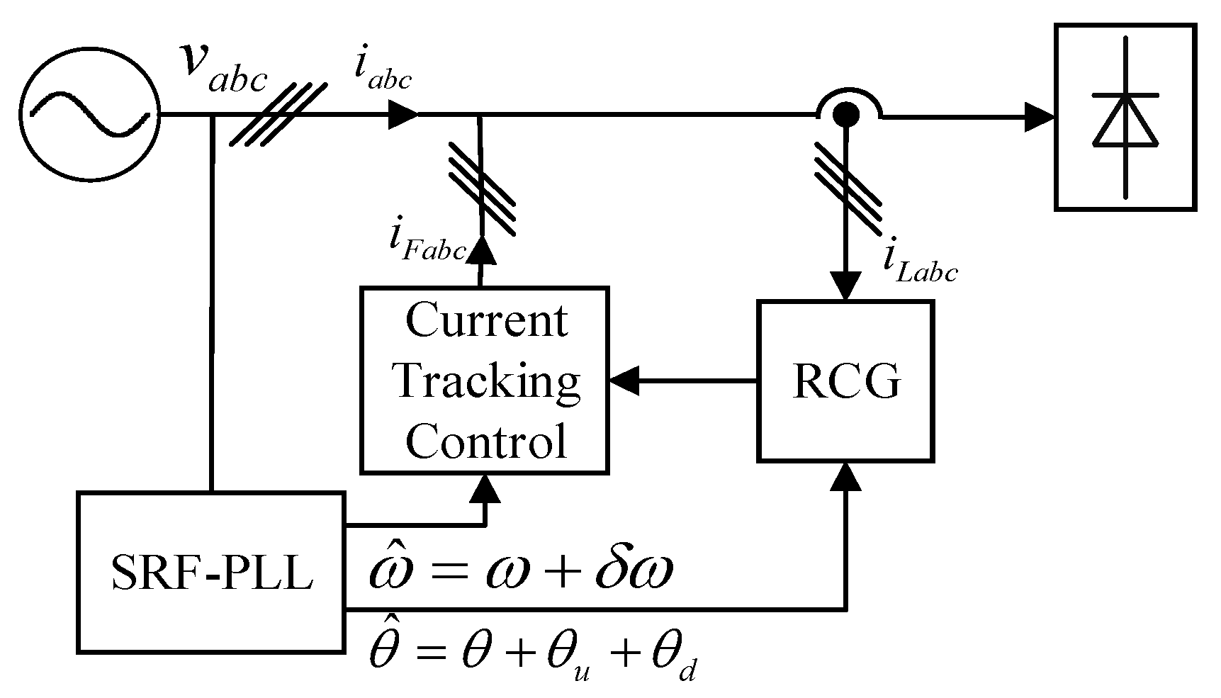
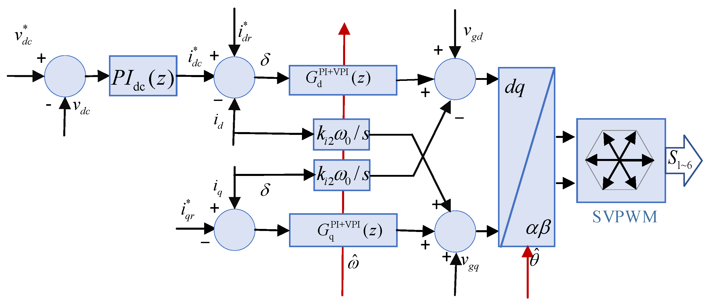
2.1. Three-Phase SRF-PLL and APF Control System

Figure 1 presents the control structure of a typical APF. The main circuit of the APF is composed of a voltage source three-phase conversion circuit. The AC side is connected to the common connection point by the output filter inductance, and the DC side is a capacitor, which can maintain the voltage of the DC side by storing the electric field energy. The control loop mainly includes a synchronous reference coordinate phase-locked loop module, DC side voltage regulation module, reference current generation module, current tracking control module and SVPWM module.
The three-phase SRF-PLL is responsible for locking the phase and frequency of the three-phase grid voltage at the point of common coupling. The above information is provided to the harmonic reference current generation (RCG) module and the current tracking control module. The DC-side voltage regulation module is responsible for generating the active current reference value that maintains the DC-side voltage. The reference value plus the harmonic reference current detected by the instantaneous power theory is used to obtain the reference current to be compensated. The accuracy of the above reference current depends on the accuracy of the phase angle estimation provided by the three-phase SRF-PLL.
According to the difference between the actual output current and the reference current of the APF, the current tracking control calculates the reference voltage of the AC side of the converter and further realizes the drive of inverter switching devices through the SVPWM module, controls the harmonic and reactive power compensation current required for the APF output and nonlinear load operation and realizes the compensation of harmonic and reactive power. It is worth noting that the phase angle information accuracy of the phase-locked loop module output will directly affect the current tracking control algorithm in the rotating coordinate system, and the frequency information accuracy of the phase-locked loop module output will affect the resonant current tracking control algorithm, such as PR control and VPI control.
The accuracy of the phase angle and frequency of the grid-side voltage of the three-phase SRF-PLL can directly affect the performance of the harmonic current detection and current tracking control algorithm in the rotating coordinate system, especially the performance of the resonant current control, thus affecting the harmonic compensation performance of the APF system.

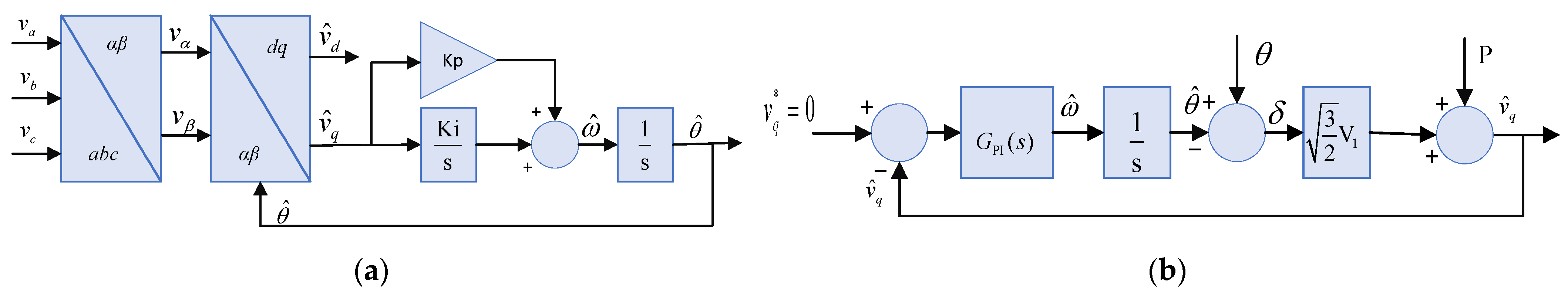
2.2. Structure and Modeling of the Synchronous Phase-Locked Loop

A Synchronous phase-locked loop is one of the most important modules in an APF system. It is not only used in the estimation of power fundamental parameters (phase, frequency and amplitude) but also in the measurement of power quality indicators, such as harmonics and inter-harmonics. The synchronous phase-locked loop ensures that the equipment connected to the grid is synchronized with the grid by accurately estimating the grid phase. The advantage of the three-phase SRF-PLL is that the measured three-phase grid voltage is transformed, and the control law is designed to make the q-axis voltage component equal to 0 to realize the synchronous tracking of the d-axis voltage to the voltage vector and then realize the tracking of the output estimation phase and frequency to the grid voltage phase and frequency. The structure and small signal model are shown in Figure 2.
The mathematical model of the three-phase balanced grid can be described as
v a = V 1 cos ( ω t ) v b = V 1 cos ( ω t 2 π / 3 ) v c = V 1 cos ( ω t + 2 π / 3 )
where θ = ωt is the grid voltage phase; then the Clarke transform is as shown in Equations (2) and (3).
v α v β = T 3 s 2 s v a v b v c
T 3 s 2 s = 2 3 1 1 / 2 1 / 2 0 3 / 2 3 / 2
When the phase-locked loop tracks the grid phase synchronously, the expression of the transformed grid-side voltage in the d-q coordinate system is shown in (4).
v d v q = cos θ sin θ sin θ cos θ v α v β = T 2 s 2 r v α v β
T 2 s 2 r = cos θ sin θ sin θ cos θ
where T2s-2r is the transformation matrix. When the d-q coordinate system rotates with V ˙ at the synchronous speed ω, the phase difference between V ˙ and d is fixed. Assuming that the phase estimation of the d-axis is θ ^ and the phase difference is δ, it can be expressed as (6), and the projection of V ˙ in the d-q coordinate system can be expressed as (7).
δ = θ θ ^
v d = 3 2 V 1 cos δ v q = 3 2 V 1 sin δ
When δ = 0, when the d-axis coincides with V ˙ , v d = V ˙ , v q = 0 . At this time, the phase between the d axis and the α axis (or the a axis) is ωt, which is the phase of V ˙ , denoted by θ = ω t . The estimated phase of the PLL output is θ ^ , as shown in Figure 2b. When tracking in steady state, δ = θ θ ^ , as
v ^ q = 3 2 V 1 sin δ 3 2 V 1 δ = 3 2 V 1 ( θ θ ^ )
In steady-state tracking, v ^ q is proportional to the deviation of phase tracking, and the proportional coefficient is 3 / 2 V 1 . In this way, the problem of accurately estimating the phase angle of the grid voltage is transformed into the problem of adjusting the output voltage component v ^ q of the q-axis to 0 under the estimated phase angle. The PI controller is used, and the transfer function is recorded as G PI ( s ) . The structure of the above synchronous phase-locked loop is shown in Figure 2a, and the linearized small-signal model under steady-state operation is shown in Figure 2b.

2.3. Influence of Grid Voltage Distortion and Unbalance

Considering the unbalanced grid-side voltage, the three-phase grid-side voltage can be written as
v a = V 1 cos ( ω t ) v b = ( 1 + γ ) V 1 cos ( ω t 2 π / 3 ) v c = ( 1 + μ ) V 1 cos ( ω t + 2 π / 3 )
where γ and μ are constants, indicating a three-phase unbalance. If ω t = θ is defined as the phase of the grid voltage and θ ^ θ in the steady state, then
θ + θ ^ 2 θ
Bring into (2), (3), (4), (5) and (6) to sort out.
v q u = 3 2 V 1 δ ( 3 + γ + μ 3 ) + 3 2 V 1 k p u cos ( 2 θ φ p u )
k p u = μ γ 2 3 2 + μ + γ 6 2
ϕ p u = arctan μ + γ 3 ( μ γ )
P q u = 3 2 V 1 k p u cos ( 2 θ ϕ p u )
Equation (14) represents the equivalent disturbance caused by the grid-side voltage unbalance. Because the q-axis voltage is adjusted to zero by the PI controller, the phase tracking error caused by the phase unbalance is:
δ u = ˜ 3 3 + μ + β k p u cos ( 2 θ ϕ p u )
The phase tracking error caused by the three-phase unbalance is twice the fundamental frequency signal.
Considering the voltage distortion, the grid voltage expression is shown in Equation (16).
v a v b v c = V 1 cos ( θ ) V 5 cos ( 5 θ ) + V 7 cos ( 7 θ ) V 11 cos ( 11 θ ) + V 1 cos ( θ 2 π 3 ) V 5 cos ( 5 ( θ 2 π 3 ) ) + V 7 cos ( 7 ( θ 2 π 3 ) ) + V 1 cos ( θ + 2 π 3 ) V 5 cos ( 5 ( θ + 2 π 3 ) ) + V 7 cos ( 7 ( θ + 2 π 3 ) ) +
Bring into (2), (3), (4), (5) and (6) to sort out:
v q d = 3 2 V 1 δ + 3 2 ( V 5 + V 7 ) sin ( 6 θ ) + 3 2 ( V 11 + V 13 ) sin ( 12 θ ) +
p q d = 3 2 ( V 5 + V 7 ) sin ( 6 θ ) + 3 2 ( V 11 + V 13 ) sin ( 12 θ ) +
Equation (18) represents the equivalent disturbance caused by the grid voltage distortion. The phase tracking error caused by the grid voltage distortion is:
δ d = ( V 5 + V 7 V 1 ) sin ( 6 θ ) + ( V 11 + V 13 V 1 ) sin ( 12 θ ) +
The tracking error caused by distortion is 6 times and 12 times the fundamental frequency signal. That is, 6 n (n = 1, 2, 3) times the fundamental frequency signal.
In summary, under the dual effects of grid voltage unbalance and distortion, when the v q steady state of the contaminated phase estimation signal satisfies v q = v q = 0 , the steady-state error of the phase angle estimation obtained by expressions (15) and (19) is shown in (20).
θ ^ = θ + 3 3 + μ + β k p u cos ( 2 θ φ p u ) + ( V 5 + V 7 V 1 ) sin ( 6 θ ) + ( V 11 + V 13 V 1 ) sin ( 12 θ ) +
According to (20), if the grid-side voltage is unbalanced and distorted and the SRF-PLL design cannot filter out undesired harmonic disturbances, the output phase estimation will have a significant disturbance error of the 2nd and 6nth (n = 1, 2, 3) harmonic frequencies. The output frequency estimation is the derivative of the output phase estimation so that it also contains the disturbance error of the same frequency.
In the APF system for harmonic compensation, the phase estimation error will lead to the given error of the harmonic current reference signal, which affects the accurate calculation of the d and q control channels, as shown in Figure 3. Obviously, improving phase and frequency estimation is important for accurate control performance.

2.4. SRF-PLL Based on the Notch Filter

Through the above analysis and derivation, it can be concluded that under the condition of unbalanced and distorted grid voltage, the conventional SRF-PLL cannot suppress each v q harmonic pollution item well. Although the bandwidth of the system can be reduced by increasing the low-pass filter to obtain better harmonic suppression, the dynamic response characteristics of the SRF-PLL will deteriorate.
For a specific number of harmonic pollution items, the interference items can be selectively removed, that is, the notch filter is used to form a notch filter-based SRF-PLL (NF-PLL), as shown in Figure 4. Each notch filter removes an unwanted harmonic disturbance item. The second-order notch filter structure is commonly expressed in two forms: (21) and (22), which are the direct form and lattice form, respectively.
N k ( z ) = 1 + a k z 1 + z 2 1 + r k a k z 1 + r k 2 z 2 1 < a k < 1
where the notch frequency is ω 0 k = arccos ( a k / 2 ) and r k determines the notch bandwidth. The relationship between r k and bandwidth satisfies B k = π ( 1 r k ) .
N k ( z ) = 1 + sin θ 2 k 2 1 + 2 sin θ 1 k z 1 + z 2 1 + sin θ 1 k ( 1 + sin θ 2 k ) z 1 + sin θ 2 k z 2
where θ 1 k < π / 2 , ω 0 k = θ 1 k + π / 2 . If taken −3 dB bandwidth is B, then B is only related to satisfy
sin θ 2 k = 1 tan ( B k / 2 ) 1 + tan ( B k / 2 )
Taking the second-order notch filter with lattice structure as an example, when the notch frequency parameters and bandwidth control parameters of the notch filter constructed by (22) are selected differently, the frequency response is shown in Figure 5. Figure 5a presents the frequency characteristics of three notch filters in series with a fixed bandwidth of 20 Hz determined by θ 2 k and notch center frequencies of 100 Hz, 300 Hz and 600 Hz determined by θ 1 k . Figure 5b presents the frequency characteristics of four notch filters with different bandwidths of 10 Hz, 20 Hz, 40 Hz and 60 Hz determined by θ 2 k and fixed center frequencies of 100 Hz determined by θ 1 k .
Based on the above transfer function of the notch filters, the open-loop transfer function of the PLL system can be expressed as:
G ( z ) = 3 2 V 1 G PI ( z ) I n t ( z ) N 1 ( z ) N n ( z )
At this time, the equivalent disturbance p = p q u + p q d , caused by Equations (14) and (18) to the estimator θ ^ transfer function, can be expressed as:
ϕ θ p ( z ) = 2 3 V 1 G ( z ) 1 + G ( z )
When the notch frequency ω 0 k of N k ( z ) in the system shown in (24) is taken as 2 ω 0 , 6 ω 0 and 12 ω 0 , the Bode diagram of disturbance to output shown in (25) is shown in Figure 6. The notch filter ensures that the NF-PLL can well suppress the 2nd, 6th and 12th harmonic interference signals caused by unbalance and voltage distortion in the control loop and can provide nearly −130 dB attenuation at the notch center frequency.

2.5. Influence of Grid-Side Voltage Frequency Deviation

Under weak grid conditions, when the voltage frequency has a large range of deviation, the attenuation of the equivalent disturbance by the above NF-PLL will be greatly reduced. As shown in Figure 6, the grid-side voltage frequency ± 4 Hz deviation will cause the attenuation of the 2nd, 6th and 12th harmonic interference to increase to −6.85 dB, −14.8 dB and −20.7 dB, respectively. The decrease in attenuation will greatly weaken the ability of the phase-locked loop to suppress interference and reduce the accuracy of phase and frequency estimation. Furthermore, it has an indirect influence on the harmonic current given link and the current tracking control link.
In theory, VPI current control can achieve zero steady-state errors in tracking the signal corresponding to its resonant frequency [29]. However, it relies on an accurate grid frequency estimation, and its transfer function is:
G VPI ( s ) = h H 2 k p h s 2 + k r h s s 2 + h ω 0 2
where k p h is the proportional gain, k r h is the resonant gain, ω 0 is the grid frequency and H is the compensated harmonic set. At the resonant frequency of the VPI controller, there is an infinite open-loop gain in theory. According to reference [29], when k p h in (26) is smaller, the frequency selectivity of the VPI controller is stronger, and for the reference current component of the corresponding resonant frequency, the VPI control can achieve better steady-state performance. Of course, considering the requirements of the dynamic performance of APF, k p h should not be too small. However, the stronger the frequency selectivity of the VPI controller, the worse the adaptability to frequency deviation. When the grid-side frequency deviation occurs, the steady-state compensation performance will decrease significantly.
Therefore, the fixed-frequency notch filter in the phase-locked loop is replaced by an adaptive notch filter with an adaptive adjustment notch frequency. On the one hand, PLL can effectively suppress the influence of 2nd, 6th and 12th harmonic interference signals under complex conditions of weak grid and obtain the phase angle and frequency information of the three-phase power grid more accurately. On the other hand, the phase angle and frequency information are used for Park transformation in VPI control and frequency parameters in VPI control law, respectively, to improve the performance of current tracking control.

3. Adaptive SRF-PLL Based on a Lattice Notch Filter

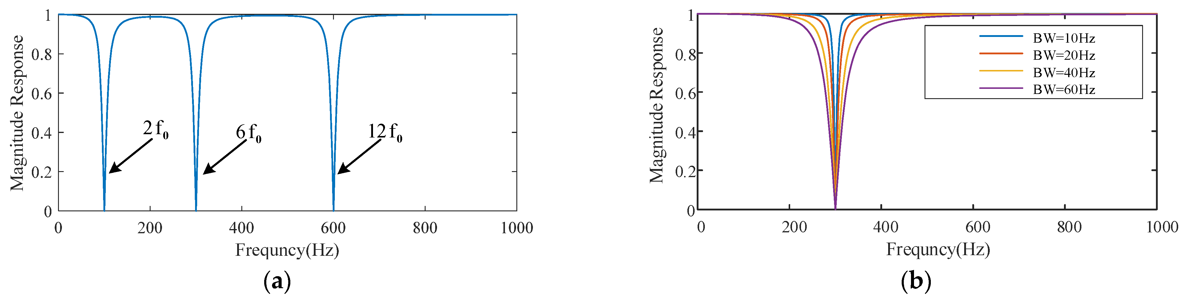
3.1. Lattice Notch Filter

Considering the problem of the limit cycle in the adaptive process of the direct form digital filter, a lattice filter is selected in this paper. Lattice filters are constructed around second-order all-pass functions.
V ( z ) = sin θ 2 + sin θ 1 ( 1 + sin θ 2 ) z 1 + z 2 1 + sin θ 1 ( 1 + sin θ 2 ) z 1 + sin θ 2 z 2
The above all-pass function satisfies V 1 ( e j ω ) = 1 for all ω , which can be written as V ( e j ω ) = e j ϕ ( ω ) , where ϕ ( ω ) is the phase-frequency characteristic function of V ( e j ω ) , is a ω monotonically increasing function and satisfies the boundary constraint ϕ ( 0 ) = 0 , ϕ ( π ) = 2 π . Then the following two functions are defined as:
N ( z ) = ( 1 + V ( z ) ) / 2
P ( z ) = ( 1 V ( z ) ) / 2
Then N ( z ) and P ( z ) are a pair of filters with complementary co-frequency characteristics, where N ( z ) is a notch filter and P ( z ) is a bandpass filter. The transfer functions are:
N ( z ) = 1 + sin θ 2 2 1 + 2 sin θ 1 z 1 + z 2 1 + sin θ 1 ( 1 + sin θ 2 ) z 1 + sin θ 2 z 2
P ( z ) = 1 sin θ 2 2 1 z 2 1 + sin θ 1 ( 1 + sin θ 2 ) z 1 + sin θ 2 z 2
It is not difficult to find that Equation (30) is the realization form of Equation (22), and the two Equations have the same frequency characteristics. The realization of the notch filter N ( z ) is shown in Figure 7b. The inner part of the inner dashed box is the structure of the lattice second-order all-pass filter. Figure 7a shows the structure of the lattice unit.

3.2. Adaptive Lattice Notch Filter

To maintain the high attenuation ability of the notch filter in the case of voltage unbalance, distortion and frequency deviation under weak grid conditions, this paper proposes an adaptive lattice notch filter based on the recursive gradient descent algorithm (RGDA). The main structure adopts the lattice structure shown in Figure 7. The parameter θ 2 that determines the notch bandwidth is fixed, and the parameter θ 1 that determines the notch frequency is dynamically adjusted by the adaptive algorithm. The goal of the adaptive algorithm is to filter out a frequency signal determined by θ 1 in y ( n ) as much as possible. Therefore, the energy of the filtered output signal can be used as an indicator function, as shown in (32), and tends to be minimized.
y ( n ) = N ( z ) u ( n )
J = E [ y 2 ( n ) ]
In this paper, the fixed θ 2 bandwidth control parameters are used, and the adaptive parameters are only θ 1 . The recursive gradient descent algorithm is used. Assuming that the adaptive step size is μ, the adaptive process is shown in (34). The last item contains the negative gradient term θ 1 ( n ) .
θ 1 ( n + 1 ) = θ 1 ( n ) + μ y ( n ) ( y ( n ) θ 1 ) θ 1 ( n )
The partial derivative of θ1 is obtained in Equation (32).
y ( n ) θ 1 = 1 + sin θ 2 cos θ 2 1 sin θ 2 2 1 z 2 D ( z ) P ( z ) x 1 ( n )
x 1 ( n ) = cos θ 1 cos θ 2 z 1 D ( z ) u ( n )
D ( z ) = 1 + sin θ 1 ( 1 + sin θ 2 ) z 1 + sin θ 2 z 2
The intermediate variable defined in (36) is the signal after the forward output delay of the θ 1 unit of the lattice filter, and (37) is the characteristic polynomial of the lattice filter. The adaptive lattice notch filter structure based on the recursive gradient descent algorithm is shown in Figure 8. The index function is a nonquadratic function of the notch frequency parameter. However, as the bandwidth determined by the parameter θ 2 decreases, the gradient E [ y 2 ( n ) ] / θ 1 will make the convergence very “dull”. If the initial frequency is far away from the notch frequency, the convergence speed will be very slow. To improve the convergence speed, the recursive gradient descent adaptive iterative expression (34) is rewritten as Equation (38). It can be proven that Equation (38) has a stronger driving ability and smaller calculation amount of the iterative algorithm, which can be called the simplified recursive gradient descent algorithm.
θ 1 ( n + 1 ) = θ 1 ( n ) μ y ( n ) x 1 ( n )
The derivation analysis of the driving terms of Equations (34) and (38) is as follows:
θ 1 E [ y ( n ) y ( n ) θ 1 ] = θ 1 E [ y ( n ) x 1 ( n ) ] , θ 1 = ω 0 π 2
E [ y ( n ) y ( n ) θ 1 ] < E [ y ( n ) x 1 ( n ) ] , θ 1 ω 0 π 2
Equation (39) indicates that the simplified gradient algorithm and the gradient algorithm can finally converge to the notch signal frequency with the same local linearization convergence model. Equation (40) indicates that in the process of frequency adaptation, the driving term of the simplified gradient algorithm is always stronger than that of the gradient algorithm, so it can ensure faster convergence speed.
Figure 9 presents the value θ 1 of the driving term when the notch frequency converges to ω 0 = 0.5 π when the notch bandwidth parameter θ 2 is 0.2 π and 0.4 π . The curve verifies the above analysis. The driving characteristics of the two adaptive algorithms overlap in the local range of the convergence frequency, and the driving term of the simplified gradient algorithm at other frequencies has a greater convergence speed. Table 1 shows the calculation process of the simplified gradient algorithm.

3.3. SRF-PLL Based on Adaptive Notch Filter

SRF-PLL based on an adaptive notch filter has been successfully applied in photovoltaic inverters and APFs [27,28]. The algorithm structure diagram is shown in Figure 10a. Three adaptive notch filters, N2(z), N6(z) and N12(z), are used to suppress the influence of the three-phase grid voltage unbalance and distortion caused by the 5th, 7th, 11th and 13th harmonics on phase or frequency tracking. According to the previous analysis, the corresponding frequency components of the above disturbance signal in the rotating coordinate system after Park transformation are the 2nd, 6th and 12th harmonic disturbances, so the above three notch filters are set. If the grid frequency deviates, the center frequency of the notch filter will be adjusted adaptively, which can fundamentally ensure that the phase-locked loop can effectively suppress the above harmonic interference when the grid frequency deviates over a wide range. To further study the stability and interference suppression capability of the phase-locked loop, a linearized small-signal model of the system is given as shown in Figure 10b. On the one hand, GPI(z) is a digital PI controller; Int(z) is a digital integrator; and V1 is the amplitude of the fundamental positive sequence grid voltage. N2(z), N6(z) and N12(z) are lattice adaptive notch filters with center frequencies set at the 2nd, 6th and 12th harmonic frequencies, respectively. The open-loop transfer function of the system can be expressed as Equation (41). The transfer function of the perturbation p to the estimator θ ^ can be obtained by Equation (25).
G ( z ) = 3 2 V 1 G PI ( z ) I n t ( z ) N 2 ( z ) N 6 ( z ) N 12 ( z )
In the case of grid voltage distortion and unbalance, the corresponding parameters of ANF-PLL shown in Table 2 are selected, where fs is the sampling frequency. At this time, the system disturbance transmission characteristics are at the rated frequency and ± 4 Hz frequency deviation, and the Bode diagram of the disturbance p to the open-loop transfer function of the estimator θ ^ is shown in Figure 11. In the case of the rated grid frequency and ±4 Hz frequency deviation, the open-loop system Bode diagram of the PLL after the adaptive steady-state can stabilize the system. The shear frequency fc is maintained at approximately 44 Hz, and the phase margin PM is maintained above 70° so that the system maintains good relative stability. In addition, it can be clearly seen that the adaptive notch filter suppresses the interference of unbalance, distortion and frequency deviation at the same time. The frequency of the grid voltage is offset, and the notch filter is effectively suppressed by adjusting the center frequency. It can provide nearly −130 dB attenuation, and its attenuation degree satisfies (42).
φ θ p ( e j 2 π f ) 130 dB f = { 2 f g , 6 f g , 12 f g ; 46 < f g < 54 } Hz

4. Adaptive VPI Current Tracking Control System

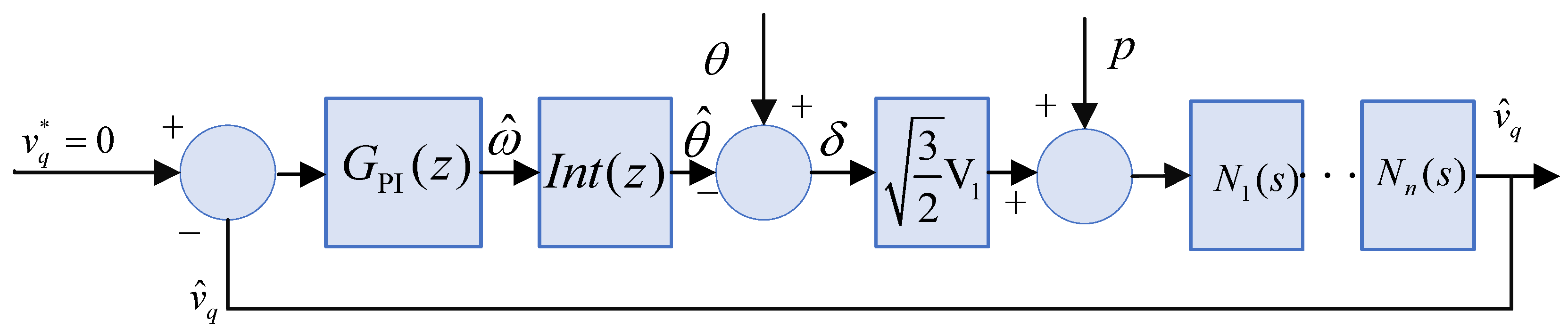
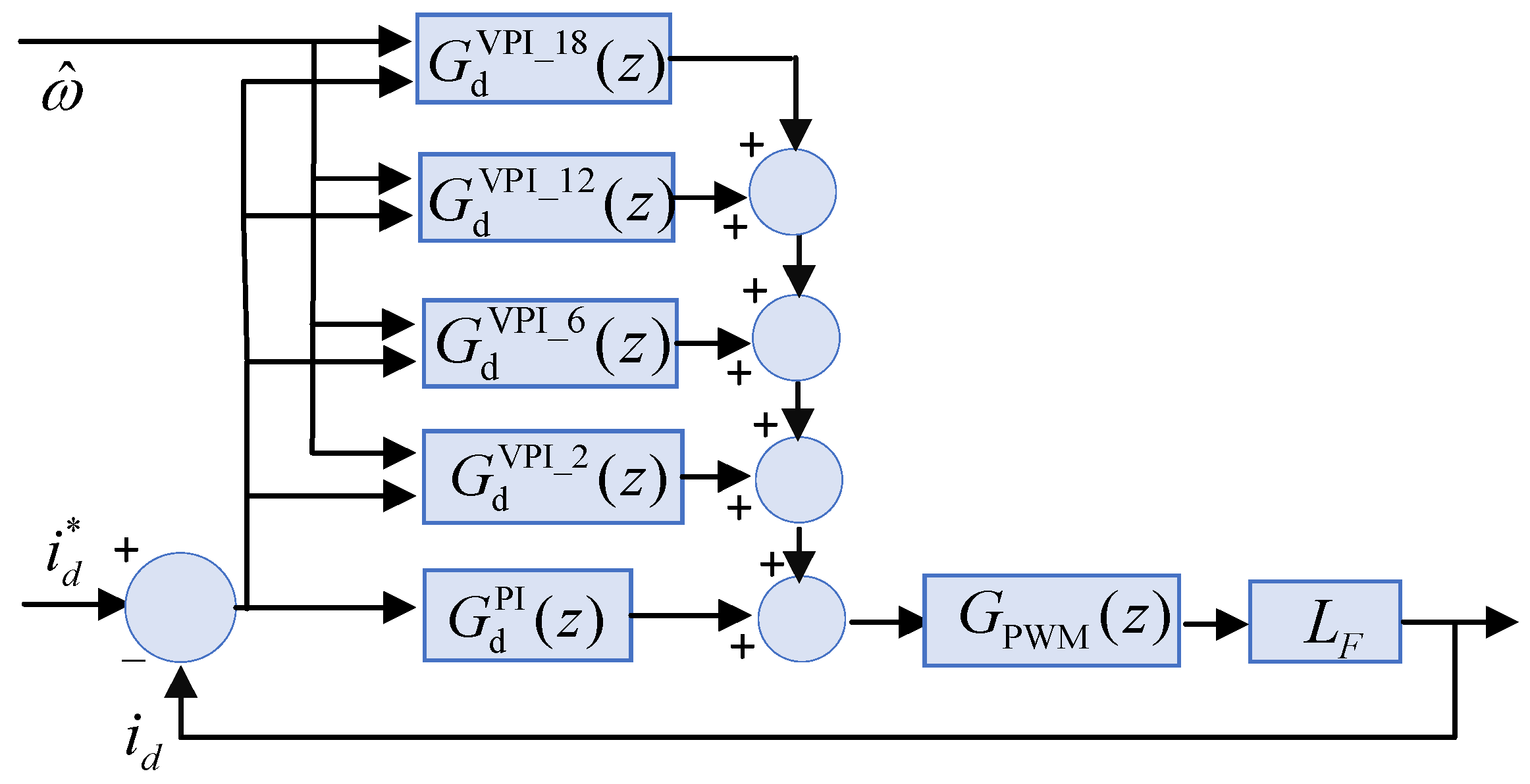
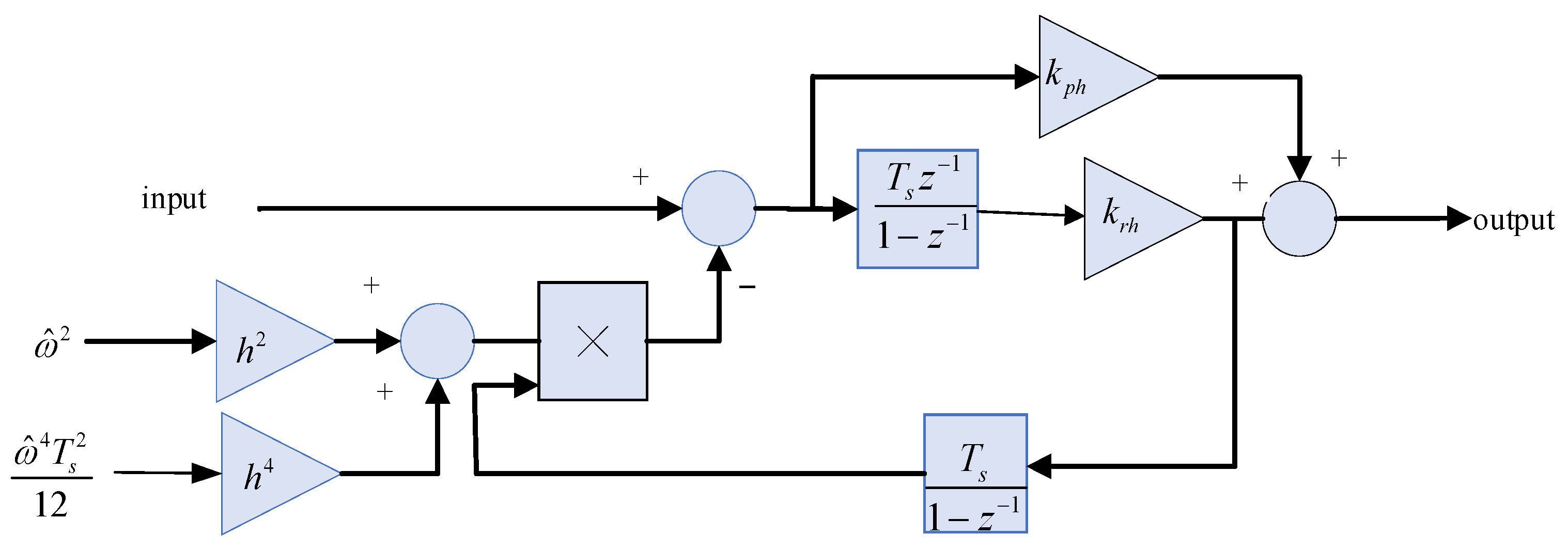
4.1. Mathematical Modeling of Digital Frequency Adaptive VPI Current Tracking Controller

As an extension and improvement of PR control, VPI control has the advantage of eliminating the peak of the closed-loop response and compensating for the delay in the system. The combination of the PI controller and VPI controller can achieve a better compensation effect [18]. The proposed frequency adaptive VPI current control scheme in this paper is shown in Figure 12. The PI controller is used to adjust the DC side voltage; the tracking output of the harmonic reference current is realized; and the harmonic compensation current is output from the PCC point. The DC side voltage regulator adopts a discrete PI integral controller, and the transfer function is P I dc ( z ) . k pdc and k idc are the proportional and integral gain of the controller, respectively. After bilinear transformation, the digital transfer function can be expressed as Equation (43).
P I dc ( z ) = k pdc ( 1 + k idc T s 2 1 + z 1 1 z 1 )
The current tracking control adopts the adaptive PI + VPI control method, and the transfer functions are G d PI + VPI ( z ) and G q PI + VPI ( z ) , respectively. The decoupled d-axis small signal current control loop is shown in Figure 13. The q-axis current control is equivalent to the d-axis in the small signal model and analysis design. Taking the d-axis as an example, G d PI + VPI ( z ) = G d PI ( z ) + G d VPI ( z ) , where the structure and parameters of the G d PI ( z ) controller are consistent with Equation (43). The transfer function of the continuous VPI controller is shown in Equation (26). Equation (44) gives the transfer function after discretization by forward Euler and backward Euler transformation. Ts is the sampling frequency of the digital controller, H = {2, 6, 12, 18}. The above discretization is a nonlinear mapping relationship for frequency, which will lead to the offset of the resonant pole of the controller and reduce the harmonic compensation ability of the resonant controller. Therefore, the cosine function term is introduced to replace the z 1 term coefficient to readjust the resonance pole position of the VPI transfer function to obtain the expected harmonic tracking performance [30]. The adjusted transfer function is shown in Equation (45). At this time, accurate mapping of the resonant frequency can be achieved. However, digitization contains a cosine function term, and online calculation means large resource consumption. Therefore, through the fourth-order Taylor series approximation, as shown in Equation (46), the maximum error of the frequency mapping generated at this time can be calculated in the 12th harmonic VPI control link. The relative error is less than 1.9 × 10 4 , and its digital implementation frame is shown in Figure 14.
G d VPI ( z ) = h H k p h + ( k r h T s 2 k p h ) z 1 ( k r h T s k p h ) z 2 1 ( 1 h 2 ω ^ 2 T s 2 / 2 ) z 1 + z 2
G d VPI ( z ) = h H k p h + ( k r h T s 2 k p h ) z 1 ( k r h T s k p h ) z 2 1 2 cos   (   h ω ^ T s   )   z 1 + z 2
G d VPI ( z ) = h H k p h + ( k r h T s 2 k p h ) z 1 ( k r h T s k p h ) z 2 1 ( 1 h 2 ω ^ 2 T s 2 / 2 + h 4 ω ^ 4 T s 4 / 24 ) z 1 + z 2

4.2. Analysis and Design of Controller

The analysis and design of the control system are based on the open-loop transfer function of the system. Through the discussion of the discrete transfer function of the controller, the controlled object is the VSC-type circuit with the output filter as the inductor. The transfer function is shown in Equation (47), and it is discretized by adding an equivalent zero-order holder [31], as shown in Equation (48). G P W M ( z ) = z 1 is the single beat delay caused by the calculation and PWM drive [16,32].
G VSC ( s ) = v d c L F s + R
G VSC ( z ) = Z T [ 1 e s T s s v d c L F s + R ]
According to Figure 14, the d-axis open-loop transfer function is:
G i d ( s ) = G d PI + VPI ( z ) G PWM ( z ) G VSC ( z )
The open-loop Bode diagram analysis method is used to analyze the stability of the current loop controller. The d-axis bandwidth is approximately 180 Hz, and the phase angle margin is approximately 70°. At the same time, the high gain of VPI control remains accurately adjusted until the 18th harmonic.

5. Simulation Analysis and Experiment

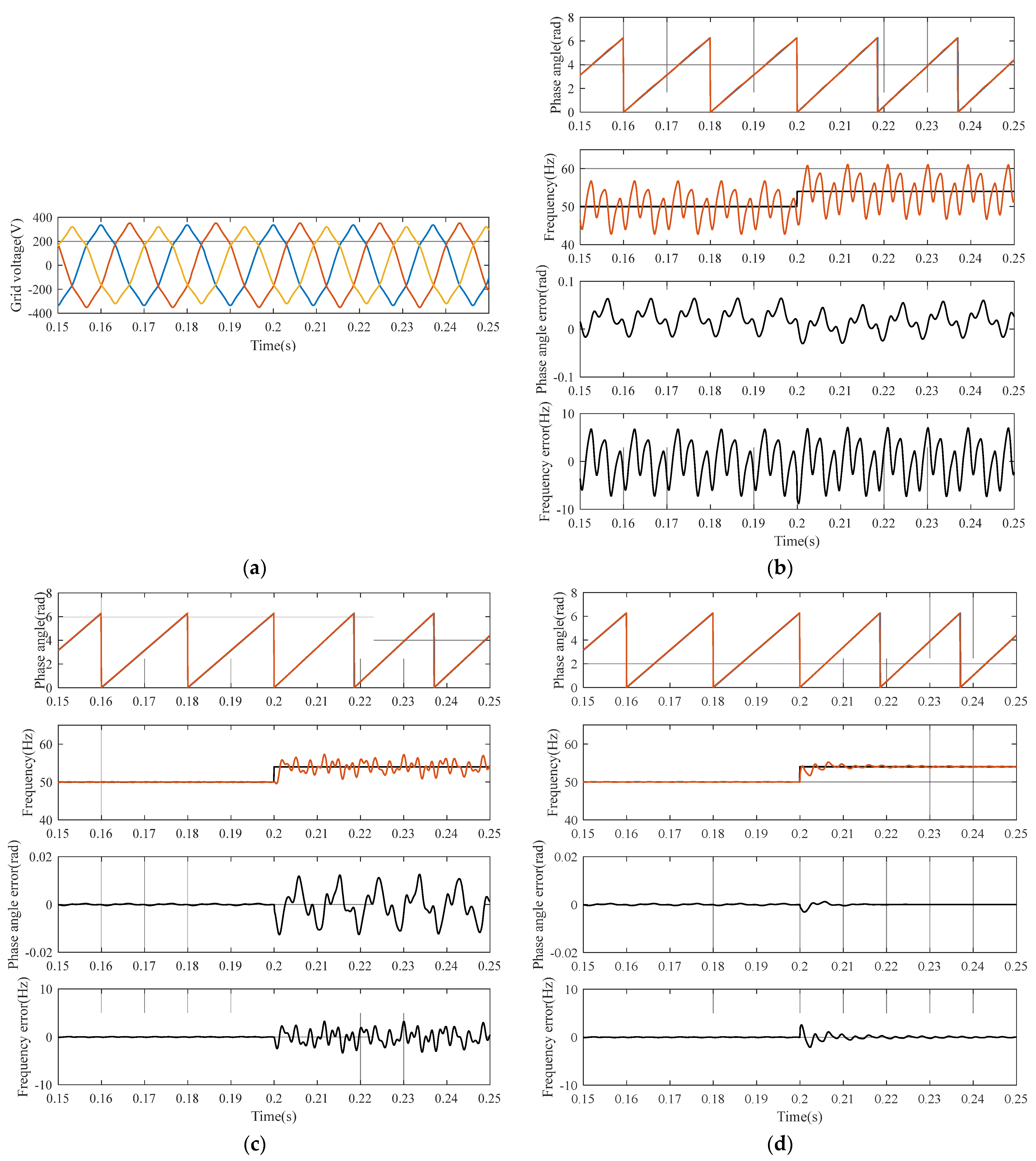
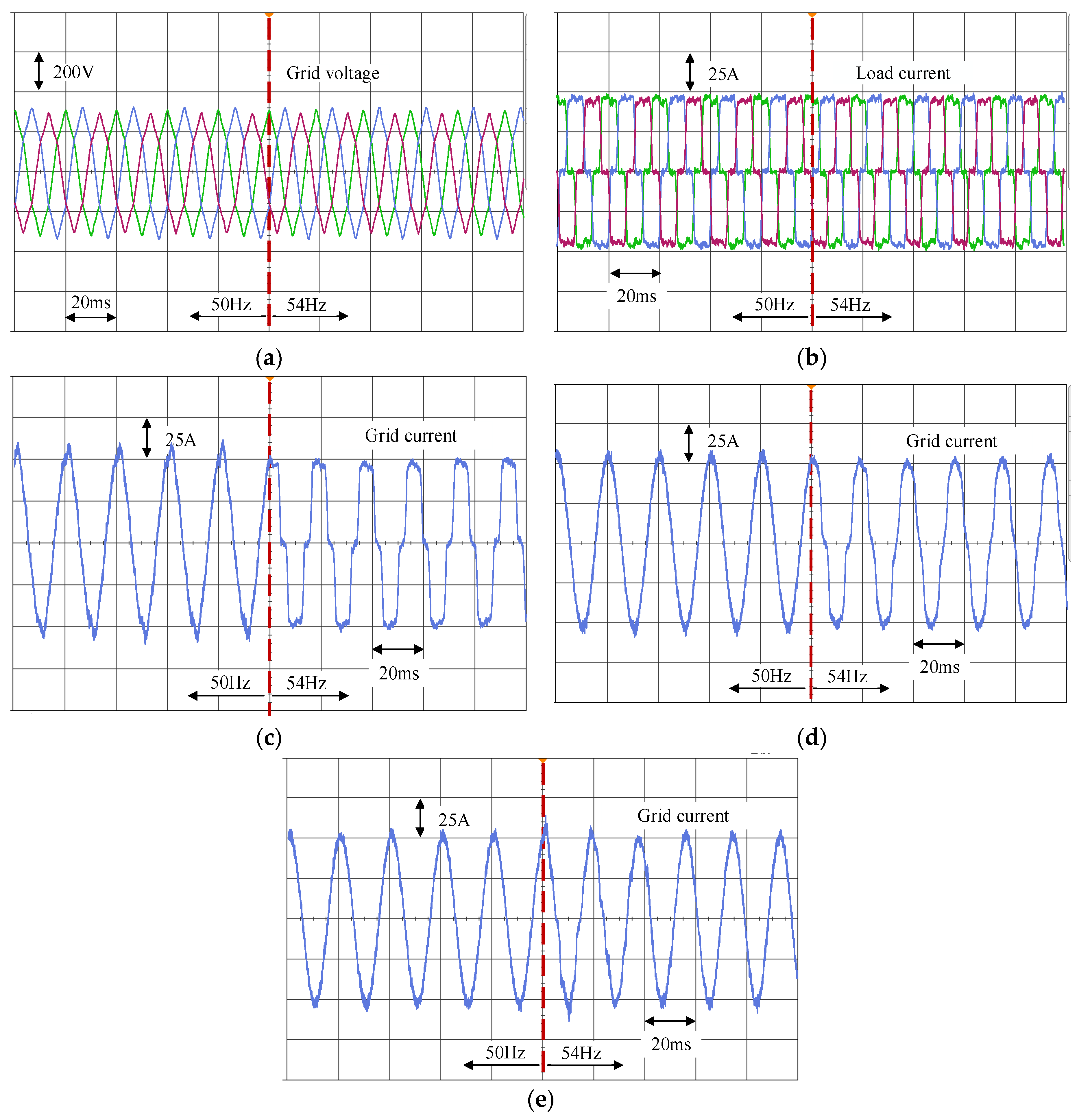
5.1. Phase-Locked Performance Verification under Various Grid Voltage Conditions

To verify the correctness and effectiveness of the proposed PLL algorithm, a simulation system based on Simulink is established. The three-phase grid voltage is unbalanced and distorted. To verify the tracking characteristics of the frequency deviation, the step frequency deviation is simulated at 0.2 s, from 50 Hz to 54 Hz. The grid-side voltage unbalance and distortion-related parameters are shown in Table 3, and the proposed synchronous phase-locked loop parameters are selected according to Table 2.
The simulation results are shown in Figure 15.
Figure 15a presents the three-phase grid voltage, the red, blue and yellow lines represent the abc three-phase of the three-phase voltage, respectively; the total harmonic distortion rate is 5.86%; and the waveform is obviously unbalanced. Figure 15b–d is the waveforms of the phase and frequency estimation and tracking error when using the three-phase conventional synchronous phase-locked loop (SRF-PLL), notch filter-based synchronous phase-locked loop (NF-PLL) and adaptive notch filter-based synchronous phase-locked loop (ANF-PLL), respectively. The following conclusions can be drawn from Figure 15b: In the case of unsatisfactory grid voltage, SRF-PLL cannot track the phase angle and frequency of the grid well regardless of whether the frequency is at the rated frequency. The phase tracking error contains obvious 2nd and 6th harmonic fluctuation components, and the maximum deviation reaches 0.06 rad. The frequency tracking error is more obvious. Before and after the frequency mutation, the maximum deviation value of the tracking error reaches approximately 7 Hz.
Through Figure 15c, it can be concluded that the NF-PLL method can better estimate the phase and frequency of the power grid even if the three-phase power supply has unbalance and distortion, and the tracking error of the two is very small. However, when the power grid changes suddenly, the tracking accuracy is reduced; the tracking error of the frequency reaches ± 4 Hz; and the tracking error of the phase angle reaches ± 0.012 rad. Nevertheless, the phase and frequency errors are much smaller than those of SRF-PLL.
Figure 15d shows that under the condition of an unbalanced and distorted three-phase power supply, the ANF-PLL method can better estimate the phase angle and frequency at the rated frequency. When the frequency changes abruptly, after nearly one fundamental cycle adjustment, the frequency can be estimated again with higher accuracy. The phase and frequency estimation errors can be maintained below 0.0005 rad and 0.2 Hz. The ANF-PLL method has the highest adaptability among the three phase-locked loops and maintains high phase and frequency tracking performance under typical weak grid conditions. High-precision phase and frequency estimation will be beneficial to support the harmonic current given link and current tracking control link, especially the VPI controller to achieve higher performance.

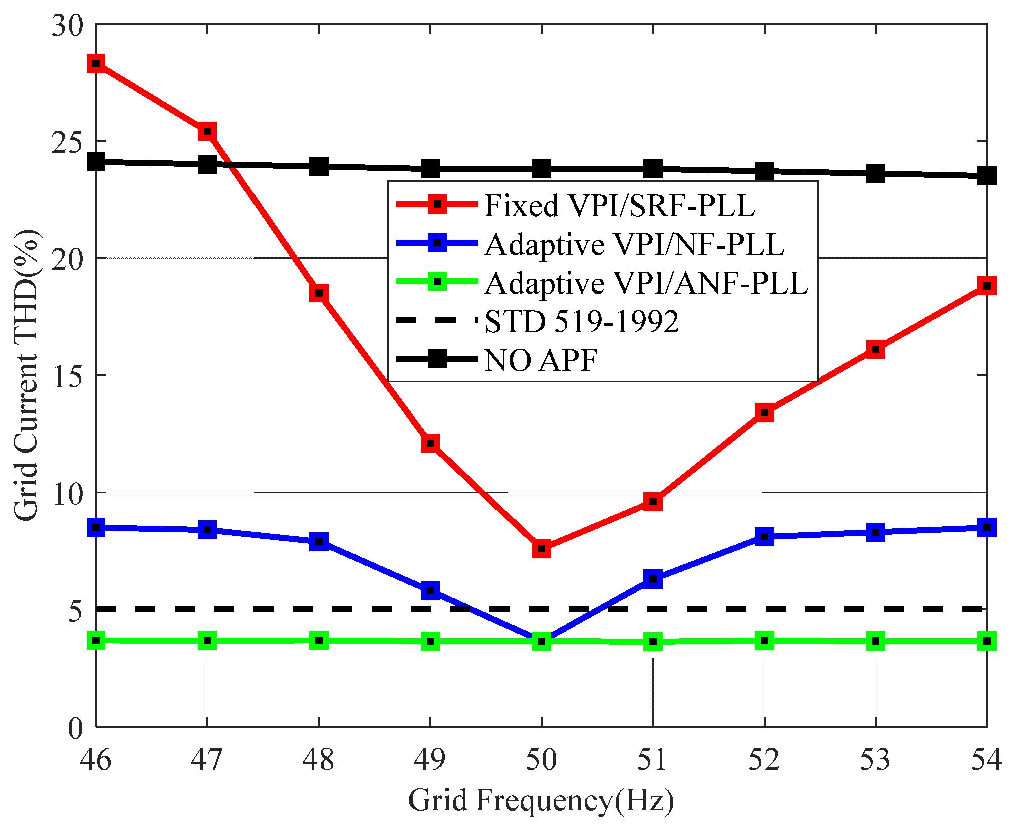
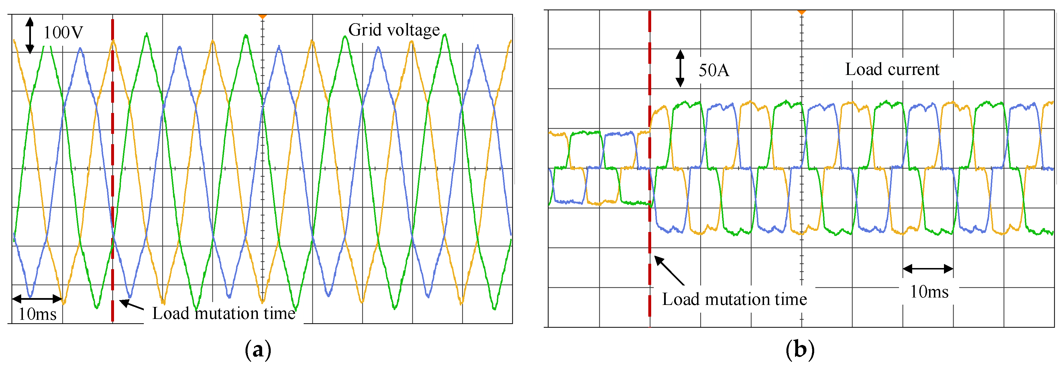
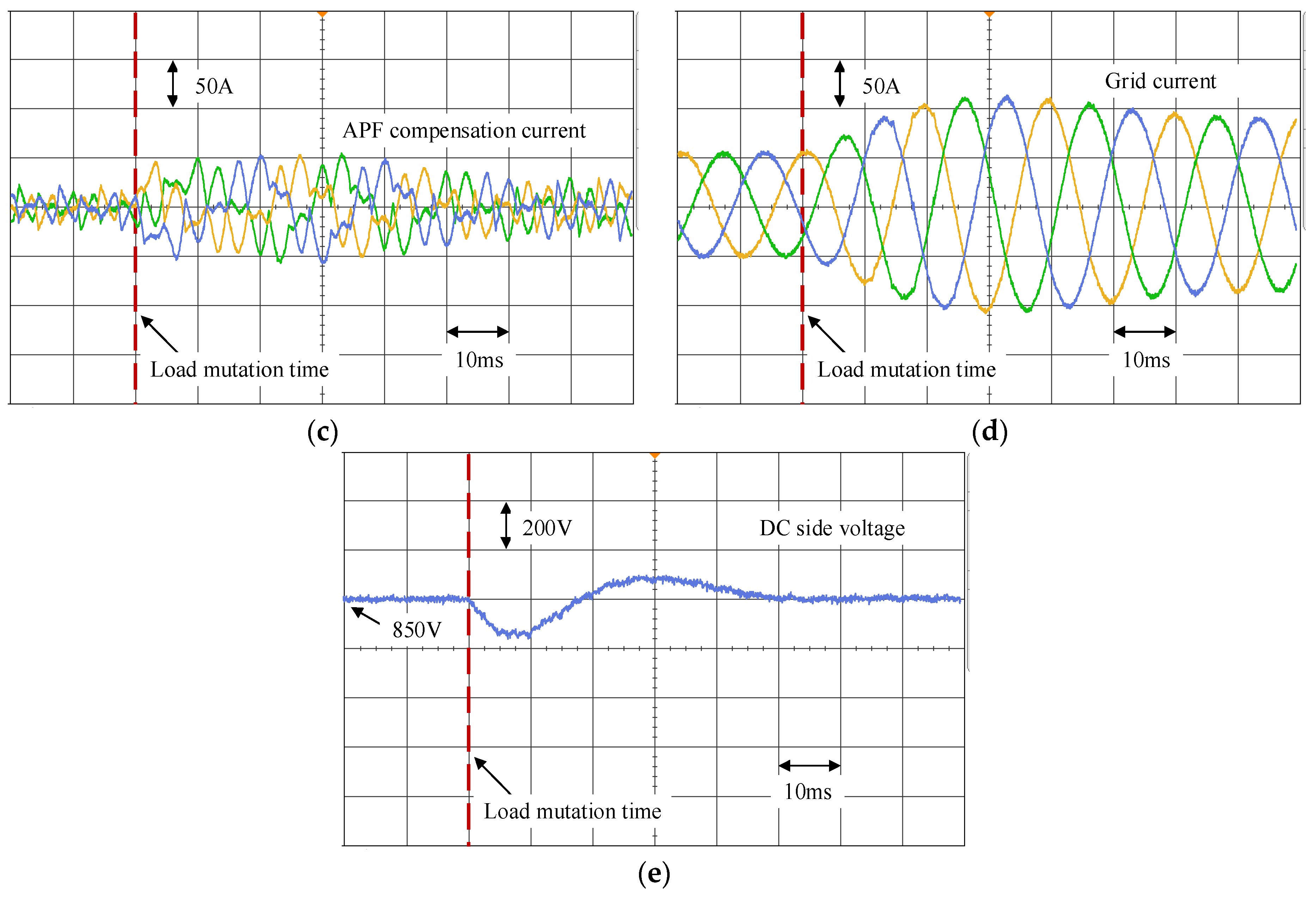
5.2. Verification of APF Compensation Performance under Weak Grid Conditions

To verify the effectiveness of the control system, a 60 kVA L-type shunt APF prototype machine is constructed (Figure 16), including the following components: (1) StarSim RCP real-time control simulation module; (2) main circuit and interface circuit part; (3) transfer board; and (4) host. The StarSim RCP real-time control simulation module is configured with Kintex-7 325T FPGA @ Xilinx and 16 analog I/O channels, with a transmission rate of 1 MB/s. The device is used to run the proposed controller and to realize real-time operation of the control code. (2) The main circuit and interface circuit part mainly include a three-phase programmable AC power supply, a voltage-source three-phase inverter circuit with output filter inductance, nonlinear load circuit, Hall-effect current and voltage transducers and an IGBT switch drive circuit. The Hall-effect current and voltage transducers sense the AC voltage and current signal of the power source, current signal of the inverter circuit and DC-side voltage signal and transmit them to the RCP circuit through an adapter plate. The IGBT switch drive module circuit receives the switching logic signal from the adapter plate and generates the switching signal to control the three-phase inverter circuit to output the harmonic compensation current. The programmable AC power supply is responsible for generating a three-phase unbalanced and distorted grid voltage with frequency mutation. Nonlinear loads are used to generate harmonic currents and to perform sudden loading operations when needed. (3) The transfer board is used to realize the signal connection between the two parts of components (1) and (2) to the component observation signals. (4) The host is used to download the control algorithm implemented in Simulink to the rapid control prototype using a code generation function and to receive and process signals of interest in the RCP module using special application software.
Table 4 provides the parameter settings of the experimental system. The measurement equipment used in the experiment mainly includes a CA8334 power quality analyzer and a DSO-X2024A digital oscilloscope, both of which can easily display the signal waveforms and their frequency spectrum.
To verify the compensation effect when the grid voltage is unbalanced, distorted and has a large frequency deviation, we compare and study the harmonic compensation performance of the APF system under three control strategies: fixed frequency VPI control plus SRF-PLL (Fixed VPI/SRF-PLL), frequency adaptive VPI control plus NF-PLL (Adaptive VPI/NF-PLL) and frequency adaptive VPI control plus ANF-PLL (Adaptive VPI/ANF-PLL).
Figure 17 presents the compensation effect comparison of the three control strategies in the case of +4 Hz frequency deviation under non-ideal grid voltage conditions. Figure 17a is the waveform of the three-phase power supply voltage, with obvious unbalance and distortion. The red, blue and green lines represent the abc three-phase of the three-phase voltage, respectively. At the time of the red dotted line, the frequency changes from 50 Hz to 54 Hz. Figure 17b is the three-phase load current; the waveform is seriously distorted; and the THD of the three-phase current reaches approximately 23.8%. If the harmonic components are not compensated, they will be injected into the grid. To more easily observe the performance of compensation, the next compensation results are shown and analyzed with the a-phase as an example. Figure 17c presents the a-phase grid current after harmonic compensation using the Fixed VPI/SRF-PLL strategy. The THD at the rated frequency is 7.6%. When the frequency changes abruptly, the compensated THD is 18.8%. Due to the unbalance and distortion of the voltage, the phase angle detection accuracy of the SRF-PLL is affected, which further affects the performance of the harmonic current reference link and the VPI controller link so that the THD after compensation at the rated frequency is higher than 5%. After the frequency mutation, the compensation performance is further reduced to 18.8% because the VPI current control link does not have frequency adaptability. At this time, the APF harmonic compensation system basically cannot play a compensation role.
Figure 17d presents the a-phase current compensated by the adaptive VPI/NF-PLL compensation strategy. It can be seen from the figure that, at the rated frequency, the notch link in the NF-PLL suppresses the disturbance caused by voltage unbalance and distortion and improves the accuracy of phase angle prediction. Therefore, the steady-state compensation performance is better, and the THD after compensation reaches 3.65%. However, when the frequency changes abruptly, the frequency non-adaptive phase angle prediction accuracy of the NF-PLL is greatly reduced, which affects the harmonic current setting and VPI tracking control link so that the THD of the compensated grid-side current reaches 8.5%. The compensation effect is poor.
Figure 17e presents the a-phase grid-side current waveform when the adaptive VPI/ANF-PLL compensation strategy is adopted. After the rated frequency and frequency deviation occur, the system can better achieve harmonic current compensation, and the compensated grid-side current THD can be maintained at approximately 3.65%. It is proven that the proposed phase-locked loop can accurately estimate the phase angle and grid frequency under unbalanced, distorted and frequency deviation conditions. The adaptive VPI link adaptively adjusts the control law parameters according to the above information and finally achieves high steady-state compensation performance before and after the frequency deviation occurs.
The steady-state harmonic compensation results of the above various non-ideal and ideal conditions are given in Table 5. By comparing the THD of the grid-side current after steady-state compensation, it can be concluded as follows. The Fixed VPI/SRF-PLL compensation strategy can effectively compensate the harmonic current under ideal conditions; however, when the grid-side voltage is unbalanced and distorted, the compensation performance decreases, and the compensation result does not reach the standard in IEEE STD 519-1992. When the grid-side voltage further occurs +4 Hz frequency deviation, the compensation result decreases significantly, and the effective compensation of harmonics cannot be realized. The Adaptive VPI/NF-PLL compensation strategy can achieve good harmonic compensation performance both under ideal condition and conditions of unbalanced and distorted grid-side voltage; however, when the grid-side voltage further occurs +4 Hz frequency deviation, it can’t achieve effective harmonic compensation results. The VPI/ANF-PLL compensation strategy proposed in this paper can achieve relatively stable and high harmonic compensation performance under the above three working conditions and has obvious advantages in the compensation performance under the complex working conditions of the proposed weak grid.
The key to ensuring the harmonic compensation performance of APF is to maintain the resonant gain of PI + VPI control through the frequency estimation given by ANF-PLL. The steady-state compensation performance depends on the THD of the grid current after compensation. For this reason, this paper measures the compensated grid-side current THD under three harmonic compensation strategies when the grid-side voltage frequency changes from 46 Hz to 54 Hz with 1 Hz as the step size. The full-load current THD is basically maintained at approximately 23.8%, and the experimental results are shown in Figure 18.
Experiments indicate that the proposed adaptive VPI/ANF-PLL can maintain a harmonic distortion rate of less than 3.68% within the frequency deviation range considered, which meets the requirements of THD less than 5% in IEEE STD 519-1992. The adaptive VPI/NF-PLL strategy can achieve a better compensation effect at the rated frequency of 50 Hz, and the harmonic distortion rate after compensation is 3.65%. However, when the frequency deviation is further increased, the THD after compensation continues to increase and finally increases to approximately 8.5%. The THD of the grid-side current after compensation of the Fixed VPI/SRF-PLL strategy at the rated frequency of 50 Hz is 7.6%, which does not meet the relevant standards. When the frequency is offset, the THD shows an upward trend with the degree of offset, reaching the maximum at 46 Hz and 54 Hz, reaching 28.3% and 18.8%, respectively, which is much higher than the standard of 5%. At this time, the APF system basically cannot achieve harmonic current compensation or even inject harmonic current into the grid side.
Based on the compensation strategy proposed in this paper, the dynamic performance of APF system harmonic compensation is verified by a load mutation experiment. The relevant experimental waveforms are shown in Figure 19. When another load with the same parameter is suddenly connected at a certain moment, the power supply voltage is unbalanced and distorted, but the frequency remains unchanged, and the current doubles when the load is connected.
Figure 19a shows a three-phase grid voltage waveform, and the green, blue and yellow lines represent the abc three-phase of the three-phase voltage, respectively. Figure 19b shows a three-phase load current waveform. After another load with the same parameter is cut in at the virtual line moment, the load current dynamically increases to 2 times the original. Figure 19c shows the APF output compensation current waveform. After the load is doubled, it enters the steady state again after approximately 2.5 fundamental cycles. The amplitude of the compensation current in the steady-state compensation reaches 2 times the original. The amplitude of the current in the dynamic transition process is larger, mainly because the sudden load causes the DC side voltage to drop. The system needs to charge the DC side through the active current. Figure 19d shows the compensated grid-side current waveform, which can maintain a good sine waveform before and after the dynamic change of the load. Figure 19e shows the waveform of the APF DC side voltage. After the load side is suddenly loaded, the voltage decreases, but it returns to the set value again after approximately 2.5 fundamental cycles. The above experimental data show that the APF system based on the proposed compensation strategy has better dynamic harmonic compensation performance.

6. Conclusions

This paper proposes an adaptive PI + VPI harmonic current compensation strategy for the complex working conditions, which can maintain the optimal operation of the APF when the grid-side voltage is unbalanced, distorted and frequency deviation occurs of a weak grid. The analysis shows that the SRF-PLL with adaptive harmonic suppression characteristics can improve the estimation accuracy of phase and frequency. The ANF-PLL adaptive parameters proposed in this paper are fewer, only one, and the simplified gradient algorithm used in the adaptive law has better convergence characteristics. The simulation results show that ANF-PLL can maintain high phase and frequency tracking performance under the conditions of grid-side voltage unbalance, distortion and frequency deviation. Before and after the frequency deviate of +4 Hz, the phase and frequency estimation errors can be maintained below 0.0005 rad and 0.2 Hz.
The adaptive PI + VPI harmonic current compensation strategy applies the grid-side frequency and phase estimation information output by ANF-PLL to the real-time VPI resonant current control link, can compensate for the 19th harmonics generated by the three-phase nonlinear load and show good harmonic current tracking performance under distortion conditions. However, when the specific harmonic content is high, an additional VPI regulator can be added to extend the APF harmonic current compensation strategy.
Compared with the fixed VPI/SRF-PLL strategy and the adaptive VPI/NF-PLL strategy, the experimental results show that the adaptive VPI/ANF-PLL harmonic compensation strategy proposed in this paper is better than the above two schemes. When the frequency deviation occurs in the frequency range of ±4 Hz, the APF system can maintain the THD of the compensated network side at approximately 3.65%, which is much higher than the requirements of the IEEE standard, and has a good dynamic transition process. When the load changes, after approximately 2.5 fundamental cycles, a new steady-state compensation is achieved.

Author Contributions

Methodology, L.Z., Z.Z. and W.H.; validation, L.Z. and W.H.; writing—original draft preparation, L.Z. and W.H.; writing—review and editing, J.Q. and W.H.; supervision, Z.Z.; project administration, L.Z. and W.H. All authors have read and agreed to the published version of the manuscript.

Funding

This work was supported in part by the National Natural Science Foundation of China under Grant 51467017, in part by the Inner Mongolia Natural Science Foundation of China under Grant 2018MS05026 and Inner Mongolia Autonomous Region Talent Development Project Foundation of China under Grant RC201701.

Institutional Review Board Statement

Not applicable.

Informed Consent Statement

Not applicable.

Data Availability Statement

The data presented in this study are available on request from the corresponding author.

Acknowledgments

The authors would like to thank the reviewers and editors for their reviews of this research.

Conflicts of Interest

The authors declare no conflict of interest.

References

  1. Fang, J.; Li, H.; Tang, Y.; Blaabjerg, F. On the inertia of future more-electronics power systems. IEEE J. Emerg. Sel. Top. Power Electron. 2018, 7, 2130–2146. [Google Scholar] [CrossRef]
  2. Chen, X.; Zhang, Y.; Wang, S.; Chen, J.; Gong, C. Impedance-phased dynamic control method for grid-connected inverters in a weak grid. IEEE Trans. Power Electron. 2016, 32, 274–283. [Google Scholar] [CrossRef]
  3. Yoon, S.J.; Tran, T.V.; Kim, K.H. Stability assessment of current controller with harmonic compensator for LCL-filtered grid-connected inverter under distorted weak grid. Appl. Sci. 2020, 11, 212. [Google Scholar] [CrossRef]
  4. Lin, P.; Shi, Y.; Sun, X.M. A Class of Nonlinear Active Disturbance Rejection Loop Filters for Phase-Locked Loop. IEEE Trans. Ind. Electron. 2021, 69, 1920–1928. [Google Scholar] [CrossRef]
  5. Pan, H.; Li, Z.; Wei, T. A Novel Phase-Locked Loop with Improved-Dual Adaptive Notch Filter and Multi-Variable Filter. IEEE Access 2019, 7, 176578–176586. [Google Scholar] [CrossRef]
  6. Mellouli, M.S.; Hamouda, M.; Slama, J.B.H.; Al-Haddad, K. A Third-order MAF Based QT1-PLL That is Robust against Harmonically Distorted Grid Voltage with Frequency Deviation. IEEE Trans. Energy Conver. 2021, 36, 1600–1613. [Google Scholar] [CrossRef]
  7. Asadi, Y.; Eskandari, M.; Mansouri, M.; Chaharmahali, S.; Moradi, M.H.; Tahriri, M.S. Adaptive Neural Network for a Stabilizing Shunt Active Power Filter in Distorted Weak Grids. Appl. Sci. 2022, 12, 8060. [Google Scholar] [CrossRef]
  8. Reza, M.S.; Hossain, M.M. Integrator-Less Method for Phase Angle Estimation of Fundamental Frequency Positive-Sequence Component under Adverse Condition. IEEE Trans. Instrum. Meas. 2021, 70, 9003010. [Google Scholar] [CrossRef]
  9. Hung, G.K.; Chang, C.C.; Chen, C.L. Automatic phase-shift method for islanding detection of grid-connected photovoltaic inverters. IEEE Power Eng. Rev. 2007, 22, 55. [Google Scholar] [CrossRef]
  10. Han, Y.; Young, P.M.; Jain, A.; Zimmerle, D. Robust Control for Microgrid Frequency Deviation Reduction with Attached Storage System. IEEE Trans. Smart Grid 2014, 6, 557–565. [Google Scholar] [CrossRef]
  11. Rodriguez, P.; Luna, A.; Candela, I.; Mujal, R.; Teodorescu, R.; Blaabjerg, F. Multiresonant Frequency-Locked Loop for Grid Synchronization of Power Converters under Distorted Grid Conditions. IEEE Trans. Ind. Electron. 2010, 58, 127–138. [Google Scholar] [CrossRef] [Green Version]
  12. Hadjidemetriou, L.; Kyriakides, E.; Blaabjerg, F. A Robust Synchronization to Enhance the Power Quality of Renewable Energy Systems. IEEE Trans. Ind. Electron. 2015, 62, 4858–4868. [Google Scholar] [CrossRef]
  13. Li, Y.; Wang, D.; Han, W.; Tan, S.; Guo, X. Performance improvement of quasi-type-1 PLL by using a complex notch filter. IEEE Access 2016, 4, 6272–6282. [Google Scholar] [CrossRef]
  14. Li, Y.; Wang, D.; Han, W.; Sun, Z.; Yuan, T. A Hybrid Filtering Stage Based Quasi-type-1 PLL under Distorted Grid Conditions. J. Power Electron. 2017, 17, 704–715. [Google Scholar] [CrossRef] [Green Version]
  15. Lee, K.-J.; Lee, J.P.; Shin, D.; Yoo, D.W.; Kim, H.J. A Novel Grid Synchronization PLL Method Based on Adaptive Low-Pass Notch Filter for Grid-Connected PCS. IEEE Trans. Ind. Electron. 2013, 61, 292–301. [Google Scholar] [CrossRef]
  16. Lascu, C.; Asiminoaei, L.; Boldea, I.; Blaabjerg, F. High Performance Current Controller for Selective Harmonic Compensation in Active Power Filters. IEEE Trans. Power Electron. 2007, 22, 1826–1835. [Google Scholar] [CrossRef]
  17. Lascu, C.; Asiminoaei, L.; Boldea, I.; Blaabjerg, F. Frequency Response Analysis of Current Controllers for Selective Harmonic Compensation in Active Power Filters. IEEE Trans. Ind. Electron. 2008, 56, 337–347. [Google Scholar] [CrossRef]
  18. Chen, J.; Shao, H.; Liu, C. An Improved Deadbeat Control Strategy Based on Repetitive Prediction Against Grid Frequency Fluctuation for Active Power Filter. IEEE Access 2021, 9, 24646–24657. [Google Scholar] [CrossRef]
  19. Yang, S.; Wang, P.; Tang, Y.; Zhang, L. Explicit Phase Lead Filter Design in Repetitive Control for Voltage Harmonic Mitigation of VSI-Based Islanded Microgrids. IEEE Trans. Ind. Electron. 2016, 64, 817–826. [Google Scholar] [CrossRef]
  20. Cao, Y.; Xu, Y.; Li, Y.; Yu, J.; Yu, J. A Lyapunov Stability Theory-Based Control Strategy for Three-Level Shunt Active Power Filter. Energies 2017, 10, 112. [Google Scholar] [CrossRef] [Green Version]
  21. Geng, H.; Zheng, Z.; Zou, T.; Chu, B.; Chandra, A. Fast repetitive control with harmonic correction loops for shunt active power filter applied in weak grid. IEEE Trans. Ind. Appl. 2019, 61, 3198–3206. [Google Scholar] [CrossRef]
  22. Shen, Y.Y.; Tsai, M.J.; Liou, Y.F.; Cheng, P.T. Active Power Filtering with A Low Switching Frequency Converter. IEEE J. Emerg. Sel. Top. Power Electron. 2021, 10, 1457–1465. [Google Scholar] [CrossRef]
  23. Wang, Y.F.; Sun, X.P.; Wang, Y.P.; Liu, C.G. Application of VPI resonance controller in SAPF. J. Liaoning Tech. Univ. 2017, 36, 96–102. (In Chinese) [Google Scholar]
  24. Liu, D.D.; Zhou, L.; Sai, X.Y. Vector-proportional-integral control of inductor-capacitor-inductor active power filter under the alpha-beta stationary coordinate system. EJEE 2020, 22, 79–86. [Google Scholar] [CrossRef]
  25. Trinh, Q.N.; Peng, W.; Choo, F.H. An Improved Control Strategy of Three-Phase PWM Rectifiers under Input Voltage Distortions and DC-Offset Measurement Errors. IEEE J. Emerg. Sel. Topics Power Electron. 2017, 5, 1164–1176. [Google Scholar] [CrossRef]
  26. Gong, C.; Sou, W.K.; Lam, C.S. Design and analysis of vector proportional–integral current controller for LC-coupling hybrid active power filter with minimum dc-link voltage. IEEE Trans. Power Electron. 2021, 36, 9041–9056. [Google Scholar] [CrossRef]
  27. González-Espín, F. An Adaptive Control System for Three-Phase Photovoltaic Inverters Working in a Polluted and Variable Frequency Electric Grid. IEEE Trans. Power Electron. 2012, 27, 4248–4261. [Google Scholar] [CrossRef] [Green Version]
  28. Hogan, D.J.; Gonzalez-Espin, F.J.; Hayes, J.G.; Lightbody, G.; Foley, R. An adaptive digital-control scheme for improved active power filtering under distorted grid conditions. IEEE Trans. Ind. Electron. 2017, 65, 988–999. [Google Scholar] [CrossRef]
  29. Trinh, Q.N.; Lee, H.H. An advanced current control strategy for three-phase shunt active power filters. IEEE Trans. Ind. Electron. 2013, 60, 5400–5410. [Google Scholar] [CrossRef]
  30. Yepes, A.G.; Freijedo, F.D.; Lopez, O.; Doval-Gandoy, J. High performance digital resonant controllers implemented with two integrators. IEEE Trans. Power Electron. 2011, 26, 563–576. [Google Scholar] [CrossRef]
  31. Dannehl, J.; Fuchs, F.W.; Hansen, S.; Thøgersen, P.B. Investigation of active damping approaches for PI-based current control of grid-connected pulse width modulation converters with LCL filters. IEEE Trans. Ind. Appl. 2010, 46, 1509–1517. [Google Scholar] [CrossRef]
  32. Figueres, E.; Garcera, G.; Sandia, J.; Gonzalez-Espin, F.; Rubio, J.C. Sensitivity study of the dynamics of three-phase photovoltaic inverters with an LCL grid filter. IEEE Trans. Ind. Electron. 2009, 56, 706–717. [Google Scholar] [CrossRef] [Green Version]
Figure 1. The control structure of a typical APF.
Applsci 13 05983 g001
Figure 2. SRF-PLL structure diagram and small-signal model: (a) SRF-PLL structure diagram; (b) SRF-PLL small-signal model.
Applsci 13 05983 g002
Figure 3. Influence of the frequency and phase angle estimation error on the APF system.
Applsci 13 05983 g003
Figure 4. The small signal block diagram of NF-PLL.
Applsci 13 05983 g004
Figure 5. Frequency response of lattice notch filters (a) under different notch frequency parameters and (b) under different bandwidth parameters.
Applsci 13 05983 g005
Figure 6. Bode diagram of PLL system disturbance to output.
Applsci 13 05983 g006
Figure 7. The structure of the lattice notch filter: (a) The structure of the lattice unit; (b) the notch filter N ( z ) .
Applsci 13 05983 g007
Figure 8. Adaptive lattice notch filter based on the recursive gradient descent algorithm.
Applsci 13 05983 g008
Figure 9. Comparison of the gradient algorithm and simplified gradient algorithm driver: (a) Wide bandwidth ( θ 2 = 0.2 π ); (b) narrow bandwidth ( θ 2 = 0.4 π ).
Applsci 13 05983 g009
Figure 10. (a) Adaptive SRF-PLL algorithm structure diagram; (b) adaptive SRF-PLL algorithm small signal model structure diagram.
Applsci 13 05983 g010
Figure 11. Bode plot of the open-loop transfer function from disturbance p to estimator θ ^ .
Applsci 13 05983 g011
Figure 12. Adaptive PI + VPI harmonic current tracking controller.
Applsci 13 05983 g012
Figure 13. Small signal block diagram of the d-axis current tracking control loop.
Applsci 13 05983 g013
Figure 14. Frequency adaptive VPI controller block diagram.
Applsci 13 05983 g014
Figure 15. Comparative study of three PLL phase frequency tracking. (a) Three-phase unbalanced and distorted grid voltage (b) wave forms for SRF-PLL, (c) wave forms for NF-PLL, (d) wave forms for ANF-PLL.
Applsci 13 05983 g015
Figure 16. Laboratory prototype of the shunt APF.
Applsci 13 05983 g016
Figure 17. Comparative experiment of the harmonic compensation performance under frequency deviation. (a) The waveform of the three-phase power supply voltage; (b) the three-phase load current; (c) the fixed frequency VPI control plus SRF-PLL (Fixed VPI/SRF-PLL); (d) the frequency adaptive VPI control plus NF-PLL (Adaptive VPI/NF-PLL); (e) the frequency adaptive VPI control plus ANF-PLL (Adaptive VPI/ANF-PLL).
Applsci 13 05983 g017
Figure 18. Comparison of THD of grid side current after compensation by three strategies.
Applsci 13 05983 g018
Figure 19. Load mutation experiment of the proposed compensation strategy: (a) A three-phase grid voltage waveform; (b) a three-phase load current waveform; (c) the APF output compensation current waveform; (d) the compensated grid-side current waveform; (e) APF DC side voltage waveform.
Applsci 13 05983 g019aApplsci 13 05983 g019b
Table 1. Simplified gradient algorithm.
Variables Known at Time nAdaptive Calculation Formula
Notch filter frequency parameters θ 1 ( n ) g 1 w = cos θ 2 sin θ 2 sin θ 2 cos θ 2 u ( n ) x 2 ( n )
Filter state parameters x 1 ( n ) and x 2 ( n ) y ^ ( n ) = 1 2 [ u ( n ) + w ]
θ 1 ( n + 1 ) = θ 1 ( n ) μ y ^ ( n ) x 1 ( n )
Input signal u ( n ) x 1 ( n + 1 ) x 2 ( n + 1 ) = cos θ 1 ( n + 1 ) sin θ 1 ( n + 1 ) sin θ 1 ( n + 1 ) cos θ 1 ( n + 1 ) g 1 x 1 ( n )
Table 2. The parameters of SRF-PLL based on adaptive notch filters.
ParametersValuesParametersValues
Kp5.364 θ 1 _ 2 ( initial ) −1.5217
Ki289.30 θ 1 _ 6 ( initial ) −1.4235
V1311 V θ 1 _ 12 ( initial ) −1.2763
fS12,800 Hz θ 2 _ 2 , θ 2 _ 6 , θ 2 _ 12 1.4309
fcApproximately 44 Hz ω 0 _ 2 2 π 100 rad/s
PMAbove 72° ω 0 _ 6 2 π 300 rad/s
μ _ 2 0.0001 ω 0 _ 12 2 π 600 rad/s
μ _ 6 0.0001BW_2, BW_6, BW_1220 Hz
μ _ 12 0.001
Table 3. Parameters of unbalance and distortion of the grid voltage.
ParametersValuesParametersValues
V 1 311 V V 5 = 0.05 V 1 15.55 V
γ 0.05 V 7 = 0.02 V 1 6.22 V
μ −0.05 V 11 = 0.008 V 1 2.49 V
THD5.86% V 13 = 0.002 V 1 0.62 V
Table 4. Parameters of the experimental systems.
ParametersValuesParametersValues
Rated voltage/frequencyThree-phase
380 V/50 Hz
Sampling frequency (equal to switching frequency)12.8 kHz
Dc-link capacitorCdc = 2000 µFDC side voltage PI regulator parameterskpdc = 1.1, kidc = 105
DC side voltage setting valueV*dc = 850 VCurrent PI controller parameterskpi = 0.75, kii = 123.8
APF output filter inductanceLF = 1 mHCurrent VPI controller parameterskph = 0.82, krh = 0.82
APF output equivalent resistanceR = 0.5 ΩPLL algorithm parametersTable 2
Dead time2.5 µsGrid-side voltage parametersTable 3
Resistive-inductive nonlinear load parametersL = 5 mH
R = 10 Ω
Table 5. Comparison of compensation results under various working conditions.
THD after Compensation for 3
Control Strategies under Various Working Conditions
under Ideal Condition (No Unbalance and
Distortion of the Grid-Side Voltage, No
Frequency Deviation)
under the Condition of
Unbalanced and Distorted
Grid-Side Voltage
under the Condition of
Unbalanced, Distorted and +4 Hz Frequency Deviated
Grid-Side Voltage
Fixed VPI/SRF-PLL3.6%7.6%18.8%
Adaptive VPI/NF-PLL3.6%3.65%8.5%
Adaptive VPI/ANF-PLL3.62%3.65%3.68%
Disclaimer/Publisher’s Note: The statements, opinions and data contained in all publications are solely those of the individual author(s) and contributor(s) and not of MDPI and/or the editor(s). MDPI and/or the editor(s) disclaim responsibility for any injury to people or property resulting from any ideas, methods, instructions or products referred to in the content.

