Article

Research on Magnetic Coupling Flywheel Energy Storage Device for Vehicles

School of Mechanical and Equipment Engineering, Hebei University of Engineering, Handan 056038, China
*
Author to whom correspondence should be addressed.
Appl. Sci. 2023, 13(10), 6036; https://doi.org/10.3390/app13106036
Submission received: 18 March 2023 / Revised: 11 May 2023 / Accepted: 12 May 2023 / Published: 14 May 2023
(This article belongs to the Section Energy Science and Technology)

Abstract

:
With the increasing pressure on energy and the environment, vehicle brake energy recovery technology is increasingly focused on reducing energy consumption effectively. Based on the magnetization effect of permanent magnets, this paper presents a novel type of magnetic coupling flywheel energy storage device by combining flywheel energy storage with magnetic coupling technology. As a high-efficiency energy storage device, it has the advantages of low energy consumption, low vibration, low noise and easy maintenance. In this paper, firstly, the structural characteristics and working process of vehicle brake energy recovery systems are analyzed, and experiments regarding the transmission and efficiency performance are carried out for key components; then a reasonable control strategy is formulated according to the principle of energy recovery; finally, the speed, acceleration, recovery energy and other parameters are analyzed based on the New European Driving Cycle (NEDC) working conditions. The results show that the energy recovery efficiency reaches 35.59%, which verifies the usability of the device.

1. Introduction

As a green energy storage method, flywheel energy storage has attracted widespread attention and has been explored and applied in many fields, such as electric vehicles, wind power generation, uninterruptible power supply (UPS), aerospace and rail transit [1,2,3].
Li Zhongrui et al. [4] used the working characteristics of flywheel energy storage to propose an optimized charging control strategy, which effectively suppressed the influence of motor loss power and load power. Li Bin et al. [5] proposed a microgrid coordinated control strategy based on a battery/flywheel electromechanical hybrid energy storage system, which adjusts the charging and discharging currents of the flywheel and battery according to the remaining capacity of the flywheel and battery, so as to reduce the power fluctuation in the microgrid caused by new energy access. Hong Yuanyuan et al. [6] used a flywheel energy storage system to realize AC-DC-AC conversion by using the internal frequency converter, which can urgently meet the power supply demand of the shock load, thereby preventing the ship’s power grid from large frequency fluctuations and accelerating fault self-healing. Chen Sizhe et al. [7] proposed a two-stage flywheel energy storage system, and the feasibility of the flywheel energy storage system for electric vehicles was verified after simulation and analysis of flywheel parameters. Fu Li et al. [8] proposed the application of flywheel energy storage technology in the field of electric vehicle braking energy recovery and increased energy utilization efficiency by storing vehicle braking energy recovery in the energy storage flywheel to provide auxiliary power when the car starts, climbs and accelerates. Studies in recent years have shown that flywheel energy storage systems have great potential for the application of electric vehicles.
Automotive brake energy recovery devices are mainly divided into electrochemical energy storage and mechanical energy storage [9]. Electrochemical energy storage converts kinetic energy into electrical energy in brake recovery and stores it. Shiwei Xu et al. [10] optimized the braking force by hierarchical control of braking energy regeneration under the premise of considering braking intent and braking compensation. Shenqin li et al. [11] proposed a distribution strategy for the braking force of the front and rear axles after considering the regenerative braking torque as limited by the charging power of the battery. Hao Lei et al. [12] coordinated the motor feedback braking force and hydraulic braking force to meet the control requirements of the braking process. Wang Weiqiang et al. [13] proposed a regenerative braking force distribution strategy based on a composite power supply system after combining the operating conditions of pure electric buses. However, due to the bottleneck in the development of batteries at this stage, this braking energy recovery strategy was limited by the material requirements of the vehicle. Considering mechanical energy storage devices is an effective way to improve the efficiency of braking energy recovery.
Vehicle braking energy recovery technology seeks to add a set of energy storage devices to the vehicle transmission system [14,15,16,17]. When the vehicle brakes, the braking energy can be recovered and stored; when the vehicle starts or accelerates, the energy stored is released, thereby improving the energy utilization efficiency.
Flywheel energy storage is a common method of mechanical energy storage. The vehicle flywheel energy storage system proposed achieves the recovery and release of vehicle braking energy through the combination and separation of clutches; however, the belt drive used has the disadvantages of high wear rate, short life and large energy loss [18]. The electromagnetically coupled flywheel energy storage system proposed achieves the recovery and release of automotive braking energy through no passage of current in the electromagnetic differential clutch; however, the energy transfer path is complex, which increases energy loss [19]. The proposed two-stage flywheel energy storage device has a larger moment of inertia under the same mass, but the flywheel meshing with the flywheel shaft through the teeth will be limited by the influence of internal stress [20]. The proposed non-high-speed planetary gear hybrid device reduces the influence of the instantaneous peak power of the car on the battery current change and efficiency by quickly outputting and recovering energy; however, the use of the planetary gear mechanism increases its structural complexity [21].
Combining flywheel energy storage and magnetic coupling transmission technology, this paper innovatively proposes a new type of magnetic coupling flywheel energy storage device for vehicles. The device controls the state of the energy storage flywheel by controlling the movement of the magnetic ring, so as to realize the conversion of the flywheel energy charging when braking and energy releasing when starting, to achieve energy recovery. It has the characteristics of simple structure, convenient maintenance and environmental friendliness and can realize the functions of heavy load starting, overload protection and energy recovery. When used in automobiles, it will greatly improve the energy utilization efficiency, increase the driving range, and play a positive role in reducing automobile carbon emissions to achieve green and sustainable development, thus promoting the realization of the dual carbon goals.

2. The Structure and Function of the Device

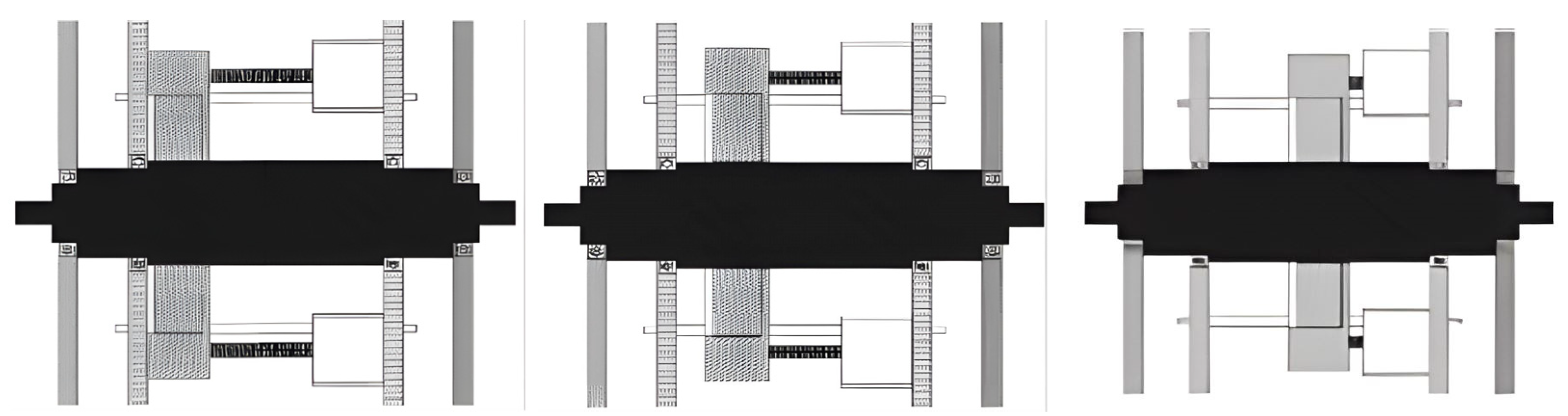
2.1. Structural Features of the Device

The magnetic coupling flywheel energy storage device fully considers the limited space inside the vehicle, adopts the compact design concept, and realizes the advantages of simple structure as well as convenient disassembly and maintenance. Using the magnetic effect, without any external energy, the device belongs to a kind of green energy-saving environmental protection equipment [22]. The schematic diagram of the layout is shown in Figure 1.
The magnetic coupling mechanism is the core component of the device; it is mainly composed of three parts: driving shaft, driven shaft, and magnetic ring. The structure is shown in Figure 2.
Driving shaft and driven shaft axis have similar installation, with both shafts comprising magnetic materials [23]. The magnetic ring is hollowly sleeved between the two shafts and can be moved axially under a pushing device. As the magnetic ring moves, the magnetization position of two shafts changes to realize the adjustment of the transferred torque and speed.

2.2. The Working Process of the Device

The magnetic ring can be adjusted to realize the combination and separation of the two shafts. The three working positions of the magnetic ring are shown in Figure 3.
When the vehicle has just started or is in a steady state, the magnetic ring is at the left end of the driving shaft. In this condition, only the driving shaft is magnetized, and the driving shaft and the driven shaft are separated. The flywheel energy storage device has no energy exchange with the vehicle.
When the vehicle starts to brake, the magnetic ring begins to move to the right, and the driven shaft is gradually magnetized with the change of the position of the magnetic ring. The braking energy is transmitted to the flywheel through the vehicle’s transmission shaft as well as the magnetic coupling device’s driven shaft and driving shaft, and then drives the flywheel to rotate and realize energy storage. When the driven shaft and the driving shaft rotate at the same speed, the energy storage ends, and then the magnetic ring returns to the left end.
After braking, when the car starts again or accelerates, the magnetic ring begins to move to the right, and the driven shaft is gradually magnetized with the change of the position of the magnetic ring. The power of the flywheel is transmitted to the wheels through the magnetic coupling device’s driving shaft and driven shaft and the vehicle’s transmission shaft, resulting in energy release. Until the two shafts rotate at the same speed, the energy release ends, and the magnetic ring returns to the left end.
When the magnetic ring is in the contact position of two shafts, the transfer torque is the largest. So, the moving range of the magnetic ring is between the left end of the driving shaft and the contact position of two shafts. The closer the magnetic ring is to the contact position of two shafts, the greater the transfer torque. The farther the magnetic ring is from the contact position of two shafts, the smaller the transfer torque.

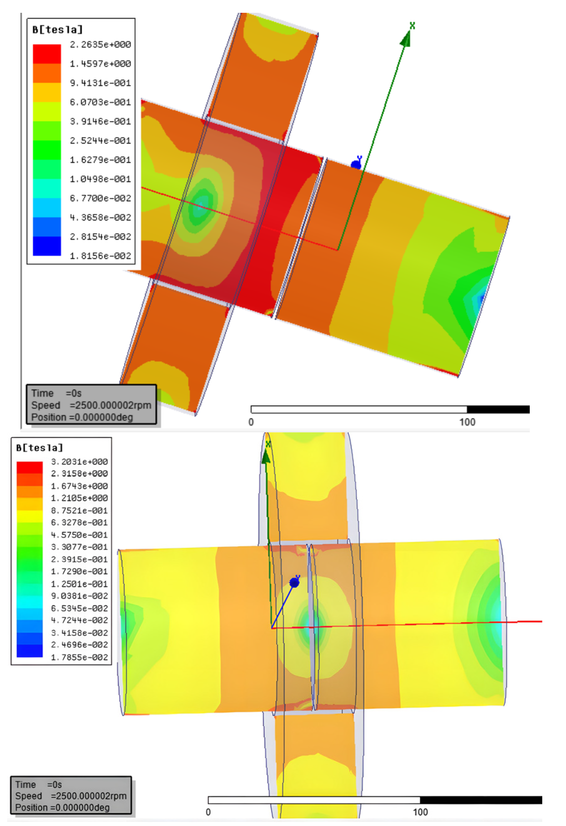
2.3. Simulation Analysis

We used Ansys Maxwell to simulate the separation state and combination state of the magnetic coupling flywheel energy storage device, as shown in Figure 4.
When the magnetic ring is in the middle of the driving shaft, the device is in a separate state, and the driven shaft is gradually magnetized, resulting in low transfer efficiency. When the magnetic ring is in the middle of the driving and driven shafts, the device is in the combined state, the driven shaft is fully magnetized, and the driving and driven shafts start to rotate synchronously.

3. Core Component Performance Test

The test platform of the magnetic coupling mechanism is built as shown in Figure 5. The platform provides the corresponding driving torque and load through the drive motor and the magnetic powder brakes, respectively, and changes the magnitude of the driving torque and load by the drive motor controller and the magnetic powder brake controller, so as to test different working conditions. Through the slide motor controller, the magnetic ring moves under the action of the slide motor, so that the driven and driving shafts are separated and coupled, thereby changing the torque transmission relationship of the driven and driving shafts.
The rotational speed, torque of the driven–driving shafts, and the load of the driven shaft are read by torque indicator and magnetic powder brake controller.
Through the working condition test, the transmission characteristics and efficiency characteristics of the mechanism are studied. The technical support for its application in the braking energy recovery system is provided.

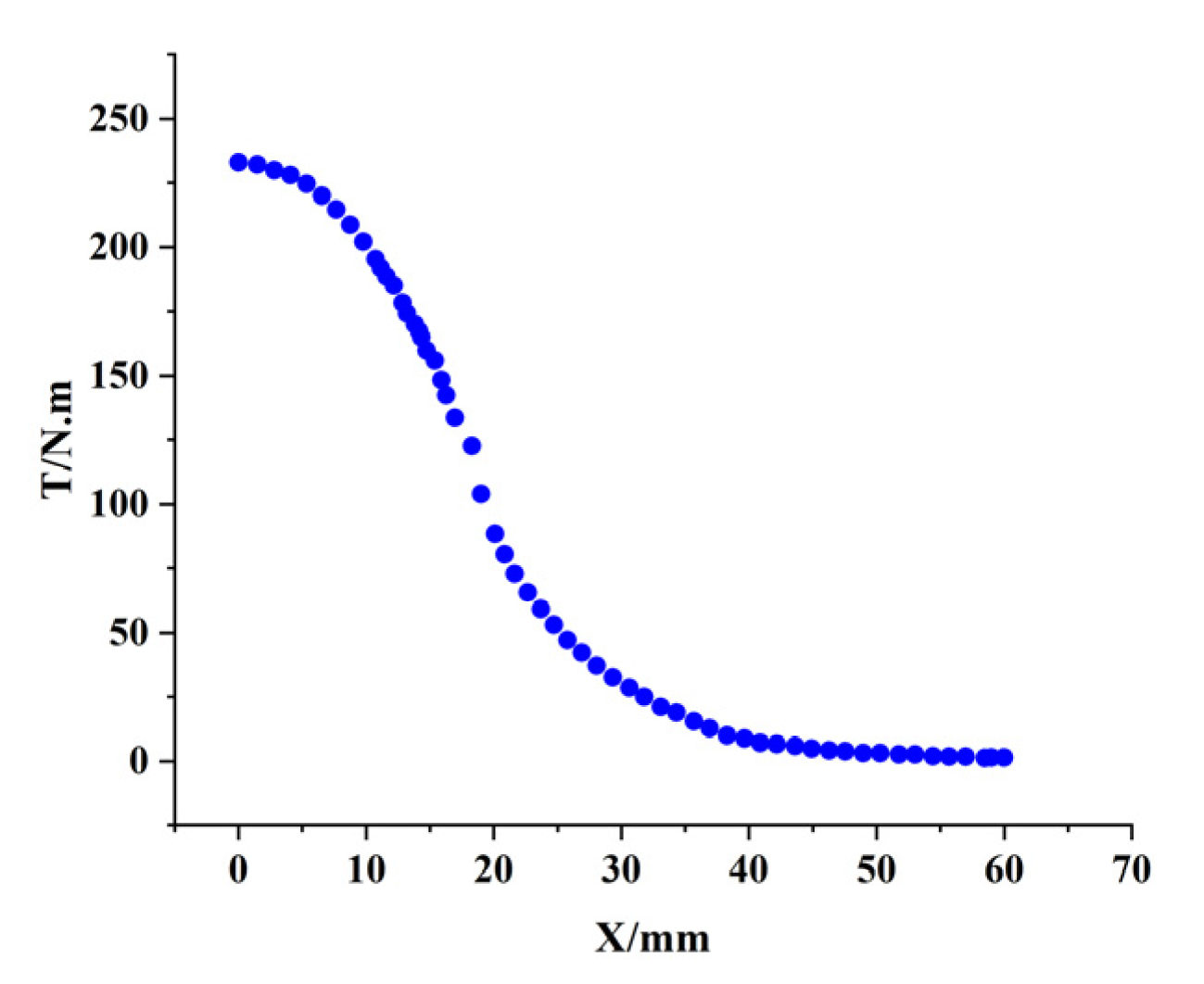
3.1. Transmission Characteristics

As shown in Figure 6, we adjusted the speed of the driving shaft to 350 r/min for testing the transmission relationship of the driving and driven shafts.
It can be seen from the test data that, with the movement of the magnetic ring, the driving shaft drives the load to start slowly through the driven shaft, and the speed of the two shafts is gradually the same. In this way, the impact and vibration in the starting process is reduced, and the damage of the motor by a large load is avoided.
The magnitude of the torque transmitted by the magnetic ring at different moving positions is tested, and the results are presented in Figure 7.
It can be seen from the test data that the movement distance of the magnetic ring is 60 mm, and the two shafts’ contact position of the magnetic ring is set as the origin. When the magnetic ring is at the origin position, the maximum transmission torque is 240 N·m; when the magnetic ring is at the left end of the shaft, the transmission torque is the smallest. With the movement of the magnetic ring, the transmission torque gradually decreases. The change of the transfer torque in the stage after 30 mm is relatively gentle.

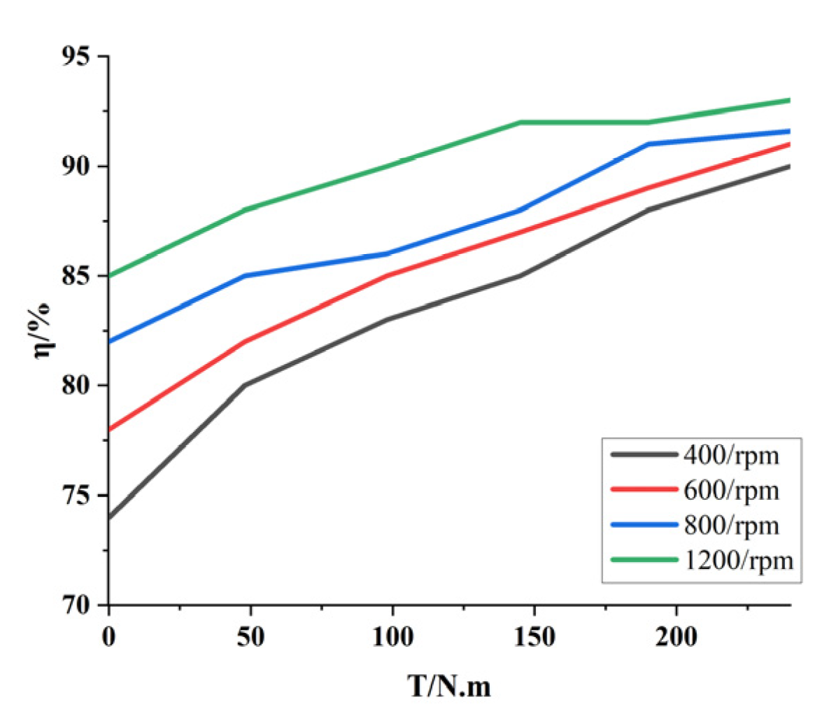
3.2. Efficiency Characteristics

According to the working principle of common permanent magnet couplers, the loss of energy is caused by the difference in rotational speed between the input and output [24]. In the magnetic coupling device proposed in this paper, the magnetic ring transmits torque and adjusts the rotational speed by moving in the axial direction. When the magnetic ring moves, there is a rotational speed difference between the main and driven shafts, which will cause energy consumption.
For a constant torque load, the power calculation formula of the drive motor is as follows:
P = T · n η
In the formula, η is the total efficiency of the transmission system.
The transmission efficiency of the magnetic coupling mechanism is defined as follows:
η = P o u t P i n = P o u t P o u t + P 0
In the formula, Pout is the output power, Pin is the input power, and P0 is the power loss.
As shown in Figure 8, we adjusted the driving shaft at four rotational speeds of 400 rpm, 600 rpm, 800 rpm and 1200 rpm to obtain different transmission torques through axial movement and tested the operating efficiency under the corresponding working conditions.
It can be seen from the experimental data that at a certain speed, the efficiency of the mechanism is positively related to the transmission torque. When the magnetic ring is in the middle of the two shafts, the transmission torque is the largest, and the transmission efficiency is the highest at this time. Similarly, when the transmission torque is certain, the efficiency is also positively related to the rotational speed. When the transmission torque is 240 N·m and the speed is 1200 rpm, the transmission efficiency can reach up to 93%, and the energy saving effect is obvious.

3.3. Error Analysis

Because there is a gap between the driving and driven shafts, and the gap is small, when the two shafts are magnetized and combined at the same time, the two shafts will squeeze the non-magnetic objects in the middle and generate friction.
At the same time, if the axiality of the two shafts does not meet the standard, it will also cause friction.

4. Principles and Strategies of Energy Recovery

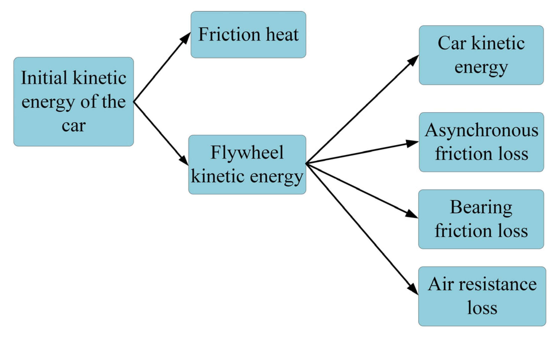
4.1. The Principle of Energy Recovery

The vehicle dynamics model with the magnetic coupling flywheel energy storage device is simplified to obtain an equivalent dynamic model, as shown in Figure 9. The main reducer and the gear train are simplified to the driven half shaft in the magnetic coupling mechanism, and a simplified model with the equivalent moment of inertia Jb is obtained. According to the states of the magnetic coupling mechanism of the car under different driving conditions, the relevant mechanical equations are derived from the three stages of starting, braking and acceleration for the equivalent model, and the mechanical analysis is carried out to obtain the energy recovery of the driving conditions.
The establishment of the equivalent mechanical model involves the following formulas [25]:
M = i = 1 k F i v i cos θ i ω + i = 1 k + M i ω i ω
J = Σ i = 1 k m i ( v s i ω ) 2 + Σ i = 1 k J s i ( ω i ω ) 2
The state of the magnetic coupling mechanism of the car based on different driving conditions is shown in Table 1:
(1) Initial stage
When the car starts, the magnetic coupling flywheel energy storage device does not work, and the magnetic ring is at the leftmost end of the driving shaft.
At this time, the two half shafts are in a separated state, and there is no torque transmission. The angular velocity of the energy storage flywheel is 0. Since the driven half shaft is connected to the vehicle through the gear train, the device and the vehicle transmission system, the following can be obtained:
ω a = 0 ω b = v a i 0 i m 3.6 r J b = δ m r 2 i 0 i m δ = 1 + I W m r 2 + I f i g 2 i 0 2 η T m r 2
where Jb is the equivalent moment of inertia of the right drive axle; ωa is the flywheel angular velocity; ωb is the left drive axle angular velocity; va is the vehicle speed; i0 is the main reducer gear ratio; ig is the transmission gear ratio; ηT is the automobile transmission efficiency; im is the energy storage flywheel gear ratio (gear train transmission ratio); IW is the moment of inertia of the wheel; m is the mass of the vehicle; r is the radius of the wheel; δ is the conversion factor of the rotating mass of the vehicle.
(2) Braking phase
Figure 10 is a schematic diagram of the mechanical model under the braking state of the vehicle:
Among them, Tm is the friction torque of the rolling bearing; Tb is the vehicle braking torque equivalent to the right drive axle; Tf is the friction torque; Tr is the vehicle resistance torque equivalent to the right drive axle; Tn is the energy storage flywheel air friction torque.
The formula for calculating the equivalent moment in the above figure is as follows:
T b = T b 1 + T b 2 i 0 i m T r = F m r i 0 i m + M m i m
where Tb1 and Tb2 is the braking torque of the two driving wheels; Mm is the motor anti-drag torque; Fm is the driving resistance of the vehicle.
According to reference [26], the calculation formula is as follows:
T m = 1 2 μ d P
where P is the bearing load; μ is the friction coefficient; d is the bearing inner diameter.
According to reference [27], the air friction torque of the energy storage flywheel is calculated by the following formula:
T n = 1 2 τ π D 2 l τ = 1 2 C f ρ υ C f = 0.664 ( Re ) 0.5 Re = ρ N D 2 μ
where τ is the surface shear stress of the energy storage flywheel; D is the diameter of the energy storage flywheel; l is the thickness of the energy storage flywheel; Cf is the local friction coefficient; v is the linear velocity of the cylinder surface; N is the rotating speed; μ is the fluid dynamic viscosity; ρ is the fluid density; D is the cylinder diameter.
When braking, the car speed is v0, the driven half-shaft angular velocity is ωb, and the driving half-shaft angular velocity is ωa.
According to the position change of the magnetic ring in the magnetic coupling mechanism, the vehicle braking deceleration is divided into two stages:
The first stage: combining stage (t1~t2)
When the car starts to brake, the magnetic ring immediately moves to the right from the left end of the driving shaft, that is, it is immediately combined, the driven shaft decelerates under the action of Mm, Fm and Tr, and the energy-storage flywheel accelerates to t2 under the action of Tr. The angular velocities of the driving shaft and the driven shaft are equal at this time. Its mechanical equation is
0 ω a t 2 J a d ω = t 1 t 2 T f T m T n d t ω b t 1 ω b t 2 J b d ω = t 1 t 2 T f T r T b d t ω a t 2 = ω b t 2 w b t 1 = v t 1 i 0 i m 3.6 r
Assuming that the road surface is flat, the tires are in normal condition, and the deceleration of the car is a1, there is no lock-up phenomenon during the braking process. The research object is the whole vehicle, and it can be known from Newton’s second law:
T r T b T f η 0 i 0 i m r = δ m a
where η0 is the mechanical transmission efficiency from the right transmission half shaft to the wheel.
Thus,
ω a t 2 = ω b t 2 = T f T m T n Δ t 1 J a Δ t 1 = t 2 t 1
During the process from asynchronous to synchronous, the main and driven shafts will be accompanied by asynchronous friction, which will generate sliding and grinding work. The calculation formula of sliding and grinding work is as follows:
W = t 1 t 2 T f ( ω a ω b ) d t
The second stage: separation stage (t2~t3)
When the angular velocity of the driving shaft and the driven shaft is equal, the energy storage ends, and the magnetic ring moves to the left immediately. The driven shaft is connected to the whole vehicle and will continue until the deceleration is completed under the action of braking torque and vehicle resistance torque. At the same time, the energy storage flywheel rotates freely due to the friction force and air resistance of the rolling bearing. In this process, the mechanics equation is
ω a t 2 ω b t 3 J a d t = t 2 t 3 T m T n d t ω b t 2 ω b t 3 J b d t = t 2 t 3 T b T r d t
Thus,
ω a t 3 = ω b t 3 = T m + T n t 3 t 2 J a
(3) Acceleration stage
The acceleration time of the car is t3~t4, the motor provides torque, the magnetic ring moves to the right, the driving and driven shafts begin to combine, the driven shaft gradually accelerates, and the kinetic energy of the flywheel is released. The mechanical model of the car during acceleration is shown in Figure 11.
Te is the motor equivalent to the output torque of the right drive half shaft, and Tr is the vehicle resistance torque equivalent to the driven shaft.
The equivalent relationship is as follows:
T e = T i m T r = F m r i 0 i m
According to the position change of the magnetic ring in the magnetic coupling mechanism, the acceleration of the car is divided into two stages:
The first stage: combining stage (t3~t4)
When the car starts to accelerate, the magnetic ring immediately moves to the right, the driving shaft is engaged with the driven shaft, and the energy storage flywheel begins to release energy. At this stage, the energy storage flywheel provides power to the vehicle, and the driven shaft accelerates. The driving shaft decelerates until the angular velocity of the driving shaft and the driven shaft are equal. Its mechanical equation is as follows:
ω a t 3 ω a t 4 J a d ω = t 3 t 4 T f T m T n d t ω b t 3 ω b t 4 J b d ω = t 3 t 4 T e T r + T f d t ω a t 4 = ω b t 4 ω b t 3 = v t 3 i 0 i m 3.6 r
If the road surface is flat, the wheels do not slip during the acceleration period, the acceleration of the vehicle is a2, and the research object is the whole vehicle. According to Newton’s second law of motion, it can be known that
T e η T T r + T f η 0 i 0 i m r = δ m a
Thus,
ω a t 4 = ω b t 4 = ω a t 3 T f + T m + T n η 0 Δ t 2 J a Δ t 2 = t 4 t 3
The second stage: separation stage (t4~t5)
When the angular velocity of the driving shaft and the driven shaft are equal, the energy release ends, the magnetic ring moves to the left immediately, the driven shaft rotates with the whole vehicle, and the energy storage flywheel decelerates under the action of Tm, Tn and Tf until the next deceleration. The mechanical equation at this stage is
ω a t 4 ω a t J a d ω = t 4 t ( T m T n ) d t

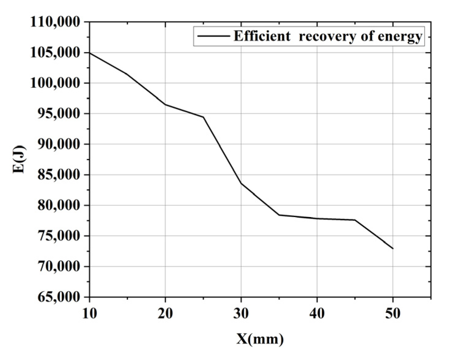
4.2. Efficient Recovery of Energy

In the interval (t1,t5), the car decelerates from braking to acceleration, and the kinetic energy of the car is converted into heat energy generated by friction and kinetic energy of the flywheel after braking and deceleration. When the car finishes braking and starts to accelerate, the kinetic energy of the energy storage flywheel will be converted into air resistance, bearing friction, energy lost by asynchronous friction, and energy fed back to the vehicle. This part of the energy is the effective recovery energy Eb, and Figure 12 is a schematic diagram of the energy flow.
The calculation formula for the effective energy recovery of the energy storage flywheel is
E b = 1 2 J a ω a t 3 2 1 2 J a ω a t 4 2 t 3 t 4 T m T n ω a d t W

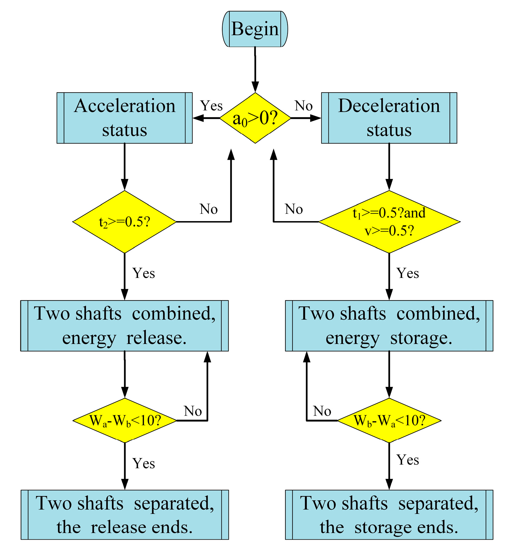
4.3. Energy Recovery Strategies

The magnetic ring of the magnetic coupling flywheel energy storage device needs to be moved to the optimal position according to the different driving conditions of the car, so that the energy storage flywheel can store more energy.
When the acceleration is equal to 0, the duration is greater than or equal to 0.5 s, and the vehicle speed is not less than 5 m/s, the vehicle is in a deceleration state. At this time, the magnetic ring moves to the right and the two shafts are combined, and the flywheel stores energy. When the angular velocities of the two shafts are equal, the magnetic ring moves to the left, the two shafts are separated, and the energy storage ends. When the acceleration is greater than 0 and the duration is greater than 0.5 s, the vehicle is in an accelerated state, the magnetic ring moves to the left, the two shafts are combined, and the flywheel releases energy. When the angular velocities of the two shafts are equal, the magnetic ring moves to the left, the two shafts are separated, and the energy release ends. When the difference in angular velocity between the two shafts is less than 10 rad/s, the two shafts are synchronized (Figure 13).
In Figure 14, a0 is the acceleration of the vehicle, v is the speed of the vehicle, t1 is the duration of deceleration, t2 is the duration of acceleration, ωa is the angular velocity of the driving shaft (also the angular velocity of the flywheel), and ωb is the angular velocity of the driven shaft.

5. Analysis of the Effect of Energy Recovery
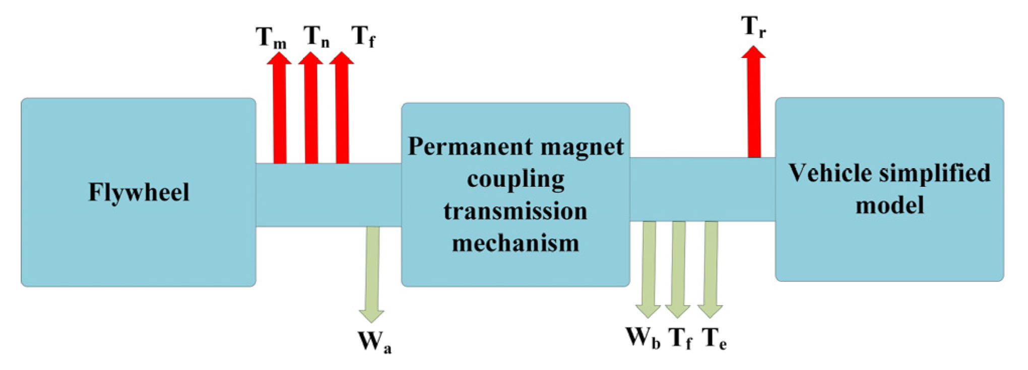
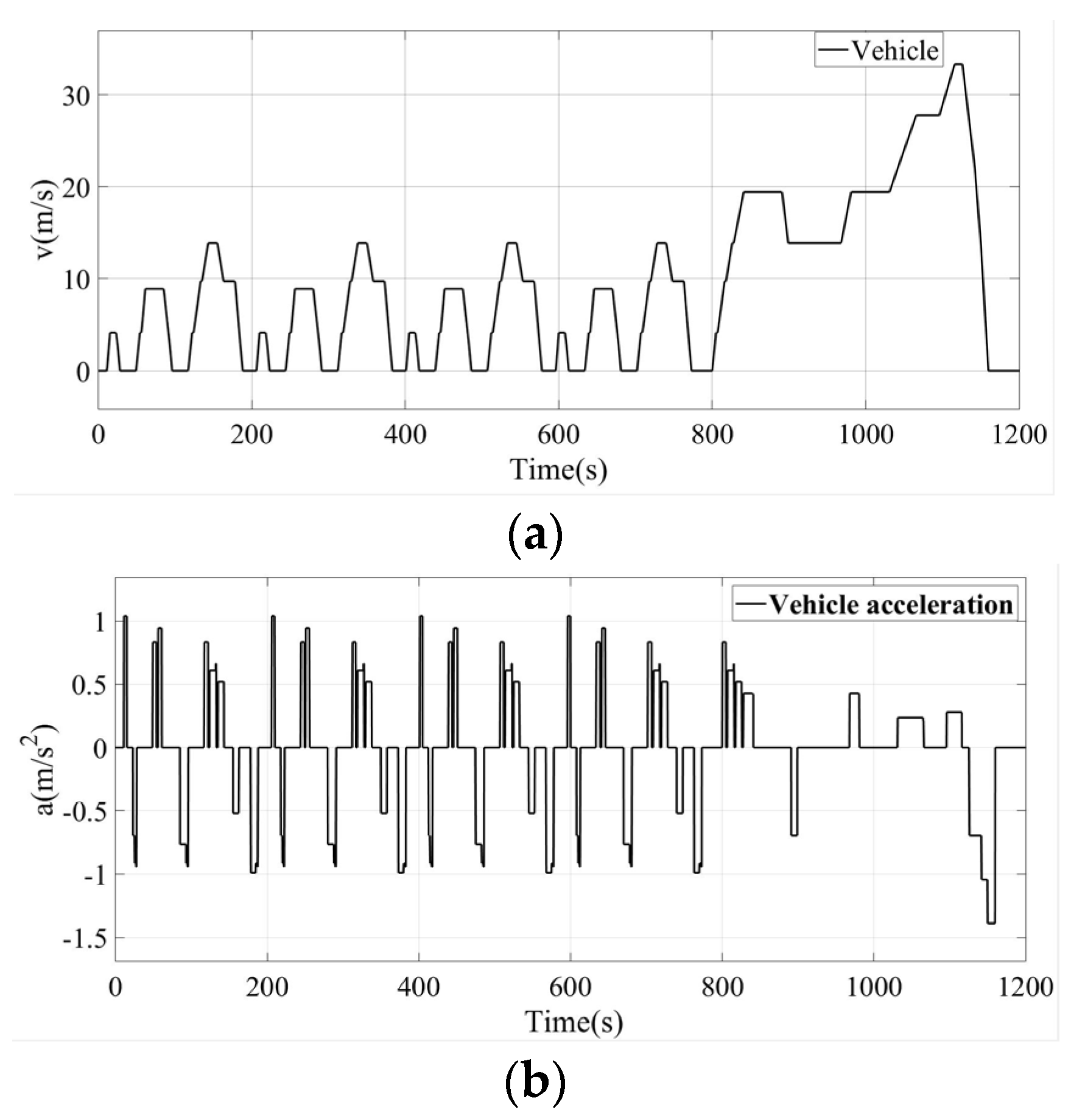
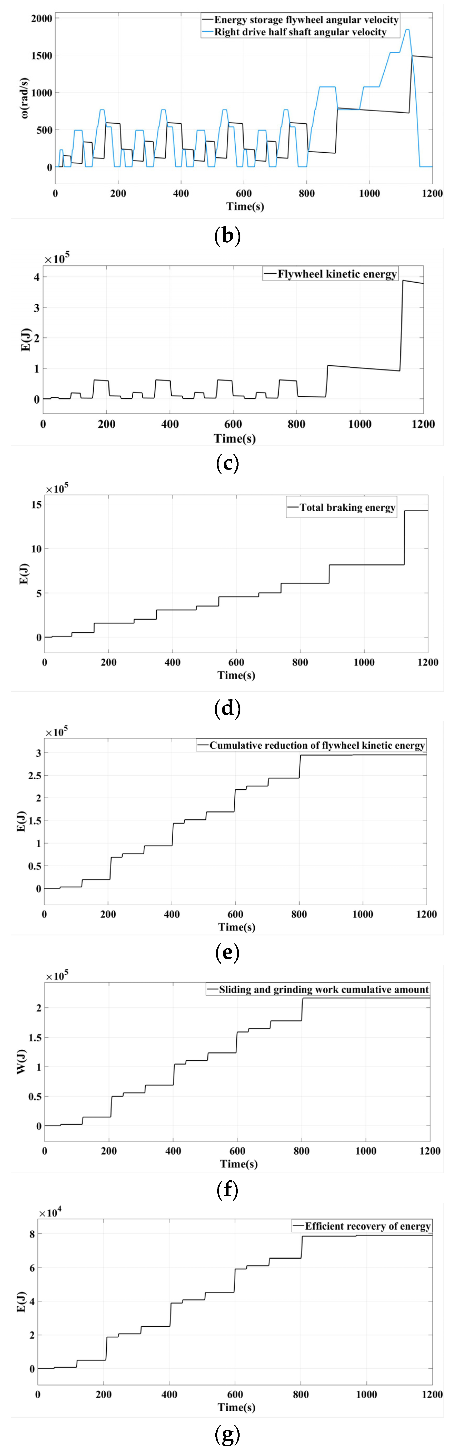
5.1. Model Building

The simulation parameters are shown in Table 2.
The recovery effect of braking energy is affected by many aspects, including the initial speed of the vehicle when braking, vehicle acceleration, and the duration of vehicle acceleration and deceleration. In this paper, the NEDC cycle condition (Figure 14) is selected for the objective evaluation of the braking energy recovery effect [28].
The time-dependent changes of parameters such as vehicle speed, vehicle acceleration, vehicle acceleration/deceleration duration, and driven shaft angular velocity are shown in Figure 15.
The model can output two states of 0, 1 or 0, −1 after logical judgment. The state of 0 and 1 means that the energy storage flywheel is in the state of accelerating energy storage, 0 means that the magnetic coupling device is in the separation state, and 1 means the vehicle decelerates; the state of 0 and −1 means that the energy storage flywheel is in the state of decelerating and releasing energy, 0 means that the magnetic coupling device is in the disengaged state, and −1 means the vehicle accelerates.

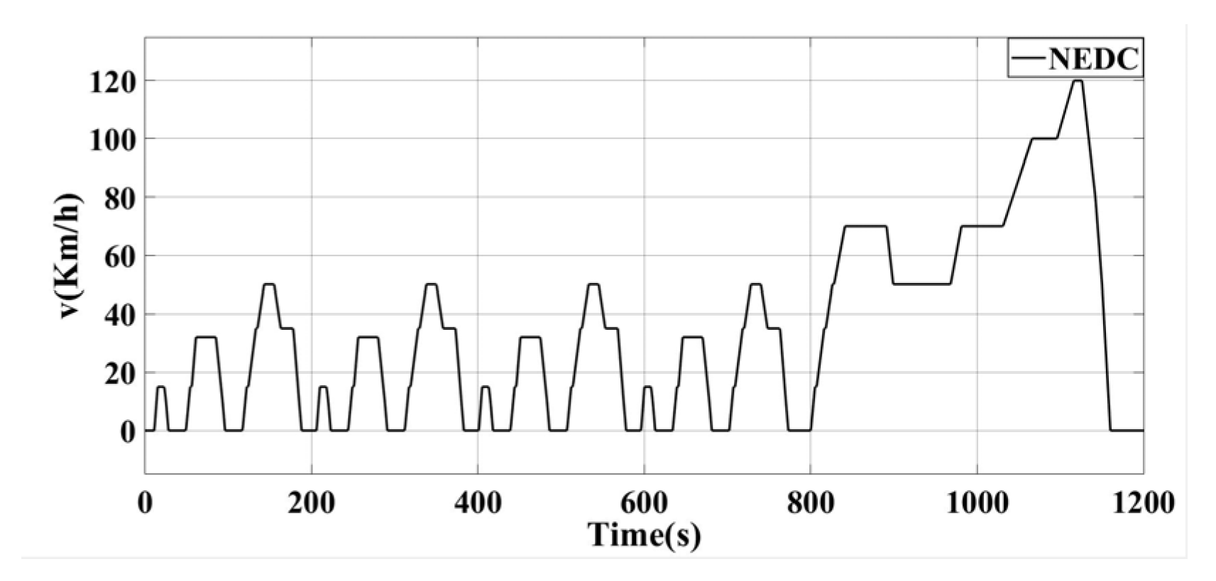
5.2. Simulation Results

During the whole simulation process, the calculation relationship of the kinetic energy reduction E when the flywheel releases energy, the sliding and grinding work W of the left and right transmission half shafts when the flywheel releases energy, and the effective recovery energy Eb is as follows:
Eb = E − W
The simulation results are shown in Figure 16.
It can be seen from the simulation results that based on the NEDC working condition, the magnetic coupling transmission mechanism combines 11 times during deceleration and 13 times during acceleration; which also means that the flywheel has 11 times the energy storage and 13 times the energy release. The braking energy of the vehicle is 1,430,000 J; when the car accelerates, the total kinetic energy reduction of the energy storage flywheel is 295,000 J; the total sliding and grinding work is 216,000 J; the effective recovery energy can reach 79,000 J.
The magnetic ring is moved from 10 mm to 50 mm, with an interval of 5 mm, and the influence of the magnetic ring on the braking energy recovery effect at different positions is further analyzed. The results are shown in Figure 17.
It can be seen from the simulation results that as the position of the magnetic ring is farther away from the middle position of the two shafts, that is, the smaller the magnetic torque, the lower the effective recovered energy. The energy is between 73,000 J and 105,000 J, and the energy recovery efficiency is up to 35.59%. For the energy recovery strategy based on fuzzy control proposed by Ma Xiaonan et al. [29], the braking energy recovery efficiency of the car is only 25.18%, and for the braking energy recovery strategy proposed by Wang Yongding et al. [30] under the same NEDC working conditions, the energy recovery rate is only 18.71%. In contrast, the energy recovery effect of this device is more obvious, which verifies the feasibility of using permanent magnet drive technology in this project.

6. Conclusions

In this paper, we combine flywheel energy storage and permanent magnet coupling transmission technology and propose a vehicle permanent magnet coupling flywheel energy storage device.
(1) Experiments show that when the speed is constant, the efficiency of the device is positively correlated with the transmitted torque. Similarly, when the transmitted torque is fixed, the efficiency is positively correlated with the rotational speed. When the transmission torque is 240 N·m and the speed is 1200 rpm, the transmission efficiency can reach up to 93%, and the energy-saving effect is obvious.
(2) The energy recovery effect of the device is simulated and analyzed based on the NEDC working condition. The simulation results show that the highest energy recovery efficiency of the device can reach 35.59%, and the recovery effect is obvious.
(3) The research results put forward a new realization scheme for the development of an automobile braking energy recovery system, which has certain theoretical research and engineering application value. In the next step, appropriate prototypes will be produced according to the selected vehicles, and real vehicle tests will be carried out to further verify the effect of the device. The effect of energy recovery shall be explored under various working conditions.

Author Contributions

Conceptualization, P.J.; Software, W.-W.N.; Formal analysis, J.-L.L.; Writing—original draft, W.-W.N. and J.-L.L.; Writing—review & editing, W.-W.N.; Visualization, W.-W.N.; Project administration, P.J.; Funding acquisition, P.J. All authors have read and agreed to the published version of the manuscript.

Funding

This work was supported by the Education Department of Hebei Province, grant Nos. CL201704 and ZD2019023.

Institutional Review Board Statement

Not applicable.

Informed Consent Statement

Not applicable.

Data Availability Statement

Not applicable.

Conflicts of Interest

The authors declare no conflict of interest.

References

  1. Hong, Z.-F. Design of High-Speed Permanent Magnet Brushless DC Motor for Flywheel Energy Storage; Zhejiang University: Hangzhou, China, 2021. [Google Scholar]
  2. Xu, F.-F. Study on Brake Energy Recycling in Subway Vehicles; Southeast University: Nanjing, China, 2017. [Google Scholar]
  3. Hu, Y.-K. High-Power Energy Storage Flywheel Control and Application in Thermal Power Systems; North China Electric Power University: Beijing, China, 2021. [Google Scholar]
  4. Li, Z.; Nie, Z.; Ai, S.; Xu, J.; Cao, M. An Optimized Charging Control Strategy for Flywheel Energy Storage System Based on Nonlinear Disturbance Observer. Trans. China Electrotech. Soc. 2023, 38, 1506–1518. [Google Scholar]
  5. Li, B.; Ye, J.-L.; Zhang, Y.; Shi, S.-S.; Wang, H.-J.; Liu, L.-L.; Li, M.-Z. Research on microgrid coordinated control strategy with distributed new energy and electro-mechanical hybrid energy storage. Energy Storage Sci. Technol. 2023, 1–7. [Google Scholar]
  6. Hong, Y.-Y.; Shi, W.-F. Impulse Load Energy Supply Strategy of Ship Regional Distribution Power System Based on Flywheel Energy Storage Technology. Ship Eng. 2023, 45, 103–109. [Google Scholar]
  7. Chen, S.-Z.; Wang, Y.-J.; Jiang, X.-Z.; Liu, Z.-L.; Lu, X.-Q. Two-stage flywheel energy storage system based on hybrid vehicle energy recovery. Technol. Innov. Appl. 2021, 11, 10–13+17. [Google Scholar]
  8. Fu, L.; Sun, S.-F.; Yang, J. Control Strategy of EV Flywheel Energy Storage System. Mach. Des. Manuf. 2019, 7, 258–262. [Google Scholar]
  9. Wang, S.-Y.; Guo, P.; Xu, Z.-N.; An, L.-C. A review of automotive braking energy recovery system research. Auto Time 2023, 402, 105–108+156. [Google Scholar]
  10. Xu, S.; Zhao, X.; Yang, N.; Bai, Z. Control Strategy of Braking Energy Recovery for Range-Extended Electric Commercial Vehicles by Considering Braking Intention Recognition and Electropneumatic Braking Compensation. Energy Technol. 2020, 8, 2000407. [Google Scholar] [CrossRef]
  11. Li, S.; Yu, B.; Feng, X. Research on braking energy recovery strategy of electric vehicle based on ECE regulation and I curve. Sci. Prog. 2019, 103, 1–17. [Google Scholar] [CrossRef]
  12. Hao, L.; Li, F.; Li, H.-J.; Zhang, X.-L. Regenerative Braking Strategy and Energy Recovery Analysis of Electric Vehicle Based on ESC. Mach. Des. Manuf. 2023, 1–5. [Google Scholar] [CrossRef]
  13. Wang, W.-Q.; Yu, T.-C.; Yan, Y.-B. Research on Regeneration Braking Energy Recovery Strategy of Electric Bus. Mach. Des. Manuf. 2023, 384, 127–131. [Google Scholar]
  14. Xiong, H.-Y.; Liu, Z.-W.; He, S. Research on Braking Energy Recovery Strategy of Double axle Drive Pure Electric Vehicle. Comput. Integr. Manuf. Syst. 2019, 36, 6. [Google Scholar]
  15. Zhou, S.; Xu, C.-L. Research on Brake Energy Recovery Strategy of Pure Electric Vehicle Based on Amesim. Manuf. Upgrad. Today 2021, 132, 56–58. [Google Scholar]
  16. Zhu, Q.-M.; Yang, J.-X.; Zhu, B.-Q.; Duan, C.-D. Research on Brake Energy Recovery System of Hydrostatic Loader. Constr. Mach. Equip. 2021, 52, 93–99+12. [Google Scholar]
  17. Jiang, G.-H. Research on braking energy recovery and storage strategy of pure electric vehicle. Energy Conserv. Environ. Prot. Transp. 2021, 17, 18–20. [Google Scholar]
  18. Li, H.-L.; Chu, J.-W.; Li, H.-G. Energy recovery characteristics of vehicle flywheel energy storage systems. J. Huazhong Univ. Sci. Technol. 2017, 45, 7. [Google Scholar]
  19. Li, H.; Chu, J.-W.; Yuan, S.-K. Performance of electromagnetic coupling flywheel energy storage devices for vehicles. J. South China Univ. Technol. 2020, 48, 8. [Google Scholar]
  20. Zhao, X.-T.; Chu, J.-W.; Yuan, S.-K. Analysis of a two-stage flywheel unit for automobile braking energy recovery. Energy Storage Sci. Technol. 2019, 8, 567–574. [Google Scholar]
  21. Sun, B.-B.; Gu, T.-Q.; Li, B.; Wang, P.-W.; Gao, S.; Wei, S.-B. Design and application of electromechanical flywheel hybrid device for electric vehicle. Energy Rep. 2022, 8, 12570–12582. [Google Scholar] [CrossRef]
  22. Li, J.-G. Study of Magnetic Force and Magnetic Moment between Permanent Magnets; Jilin University: Changchun, China, 2015. [Google Scholar]
  23. Ji, P.; Liu, J.-L. Design and research of magnetized reversing transmission device. Coal Mine Mach. 2021, 42, 12–14. [Google Scholar]
  24. Shu, H.-W. Performance Analysis of Permanent Magnet Eddy Current Couplings; Jilin University: Changchun, China, 2013. [Google Scholar]
  25. Pan, Y.-S. Mechanical Principles; Chongqing University Press: Chongqing, China, 2016. [Google Scholar]
  26. Wang, T.-F.; Li, H.-J. The bearing stress field finite factor calculation of high-power direct drive wind turbine. Small Spec. Electr. Mach. 2021, 49, 24–27. [Google Scholar]
  27. Huang, J.-H.; Wang, F.-Z.; Yang, J.-P. Research on the brake energy recovery system of flywheel vehicles. J. Syst. Simul. 2016, 28, 1197–1205. [Google Scholar]
  28. Yuan, L.-H.; Zhong, R.-M.; Huang, Z.-P. Research on energy feedback calibration of pure electric vehicles based on NEDC. Intern. Combust. Engine Parts 2021, 342, 182–183. [Google Scholar]
  29. Ma, X.-N.; Ji, C.-Y.; Xu, E.-Y.; Zheng, W.-G. Research on Brake Energy Recovery Strategy of Rear-drive Pure Electric Vehicle. Mach. Des. Manuf. 2023, 1–4. [Google Scholar] [CrossRef]
  30. Wang, Y.-D.; Pei, K.-Y. Research on Optimization of Braking Energy Recovery Strategy for Pure Electric Vehicles. Mech. Sci. Technol. Aerosp. Eng. 2022, 41, 1436–1441. [Google Scholar]
Figure 1. Layout diagram.
Applsci 13 06036 g001
Figure 2. Structural model diagram.
Applsci 13 06036 g002
Figure 3. Three working positions of the magnetic ring.
Applsci 13 06036 g003
Figure 4. The magnetic induction intensity of the device in the separated and combined states.
Applsci 13 06036 g004
Figure 5. The test platform.
Applsci 13 06036 g005
Figure 6. Diagram of speed and time.
Applsci 13 06036 g006
Figure 7. Relation between ring position and torque.
Applsci 13 06036 g007
Figure 8. Efficiency changes with torque and speed.
Applsci 13 06036 g008
Figure 9. Simplified model diagram.
Applsci 13 06036 g009
Figure 10. Schematic diagram of mechanical model during braking.
Applsci 13 06036 g010
Figure 11. Schematic diagram of mechanical model during acceleration.
Applsci 13 06036 g011
Figure 12. Schematic diagram of energy flow.
Applsci 13 06036 g012
Figure 13. Control flow.
Applsci 13 06036 g013
Figure 14. NEDC cycle.
Applsci 13 06036 g014
Figure 15. Parameter plot over time. (a) Vehicle speed, (b) Vehicle acceleration, (c) Deceleration duration, (d) Acceleration duration, (e) Angular speed of right drive half shaft.
Applsci 13 06036 g015aApplsci 13 06036 g015b
Figure 16. Simulation result graph. (a) State diagram of magnetic coupling transmission mechanism, (b) Angular velocity diagram of energy storage flywheel and right transmission half shaft, (c) Kinetic energy variation diagram of energy storage flywheel, (d) Vehicle braking energy accumulation diagram, (e) Accumulation diagram of kinetic energy reduction of energy storage flywheel, (f) Sliding wear work accumulation diagram, (g) Effective energy recovery.
Applsci 13 06036 g016aApplsci 13 06036 g016b
Figure 17. Effective energy recovery at different locations of magnetic ring.
Applsci 13 06036 g017
Table 1. State diagram.
Vehicle StatusStartBrake DecelerationAccelerate after
Deceleration
Permanent magnet coupling transmission mechanism statusDisconnectionCombine and then disconnectCombine and then disconnect
Energy storage
Flywheel status
There is damping for free rotationStorage energyRelease energy
Drive modeMotorNoMotor and flywheel
Time division(0,t1)(t1,t2) and (t2,t3)(t3,t4) and (t4,t5)
Table 2. Simulation parameters.
Parameter NameValue
Tire roll radius (r/mm)0.362
Vehicle mass (/kg)1100
Main deceleration ratio4
Transmission efficiency92
Pavement slope ( α )0
Air resistance coefficient ©0.32
Windward area (A/m2)2
Pavement adhesion coefficient0.75~0.9
Magnetic ring position (a/mm)35
Friction torque ( T f / N m )30
Gear train reduction ratio5
The moment of inertia of the flywheel ( J a / k g m 2 )0.35
Energy storage flywheel quality (/kg)40.14
Disclaimer/Publisher’s Note: The statements, opinions and data contained in all publications are solely those of the individual author(s) and contributor(s) and not of MDPI and/or the editor(s). MDPI and/or the editor(s) disclaim responsibility for any injury to people or property resulting from any ideas, methods, instructions or products referred to in the content.

