Article

Free Vibration Characteristics Analysis of Metal-Rubber Cylindrical Shells Based on Viscoelastic Theory

School of Mechanical Engineering and Automation, Northeastern University, Shenyang 110819, China
*
Author to whom correspondence should be addressed.
Appl. Sci. 2023, 13(10), 6085; https://doi.org/10.3390/app13106085
Submission received: 24 March 2023 / Revised: 20 April 2023 / Accepted: 25 April 2023 / Published: 16 May 2023
(This article belongs to the Section Mechanical Engineering)

Abstract

:
The cylindrical shell made of metal rubber has a strong ability to reduce and absorb vibration, which widens its application in the industrial field. Therefore, it is of great significance to study the vibration characteristics of metal-rubber cylindrical shells (MRCSs). However, there is relatively little research on this aspect. Based on this, the dynamic properties of MRCS are investigated in this paper based on viscoelastic theory, the Rayleigh–Ritz method, and the Gram–Schmidt orthogonal polynomials. The correctness of the proposed model was verified by comparison with the literature and experimental verification. The results show that the preloading state and boundary conditions have significant effects on the natural frequency and modal loss factor of MRCS. The effect of the Pasternak elastic foundation on the natural frequency and modal loss factor of MRCS varies with the change of the axial half wave number m. The effect of the Pasternak elastic foundation on higher-order vibrations is similar to that of the artificial spring technique.

1. Introduction

Metal rubber (MR) is a type of porous material made by helix wire braiding and molding. MR is named for its similarities to rubber materials in terms of mechanical properties, although some researchers refer to it as entangled metallic wire material [1,2], metal wire mesh [3], or pseudo-rubber [4]. MR is known for its high stiffness and damping properties, as well as its resistance to high and low temperatures [5], aging [6], corrosion [7], and impact [8,9,10]. Given these properties, MRCSs are widely used in practical engineering applications. However, to avoid resonance-induced inefficiencies and structural damage, it is important to perform a vibration analysis of these shells. Therefore, there is significant technical significance to conducting such analyses.
Due to the uncontrollable change of metal wire during the die-pressing process, MR exhibits strong randomness in its internal structure. As a result, the focus of most research has been on developing a constitutive model of MR and conducting experimental research on its mechanical properties. Several models have been proposed to predict various properties of MR with high accuracy. Chegodaev et al. [11] proposed the helix cell model to predict its static properties. Ma et al. [12] developed the inclined helix pyramid (IHP) model to predict the nonlinear stiffness and temperature dependence of MR. Xue et al. [13] used an enhanced constitutive model to accurately predict the hysteresis curve of MR and discussed the dynamic characteristics of stiffness and energy consumption. Ren et al. [14] predicted the spatial distribution of wire turns and the interior of MR using the micro spring element with the adaptive deformation (MSEAD) model and the evolution of contact friction. Ma et al. [15] discovered the existence of a boundary layer in MR using X-ray tomography. Zhang et al. [16] conducted experiments to study the influence of relative density on the tangential modulus and loss factor of MR. Among these models, the IHP model stands out due to its high accuracy and consideration of the influence of process parameters. Hence, in this paper, the IHP model is used to calculate the mechanical properties of MR.
Apart from MR, research on composite shell structures has become increasingly in-depth due to their widespread use. Specifically, the analysis of the vibration characteristics of shells made of functionally graded materials has attracted attention in recent years, and many researchers have devoted significant efforts to it [17,18,19]. Do et al. [19] analyzed the vibration and static buckling behavior of variable thickness flexible nano-plates based on the shear deformation theory of hyperbolic sinusoidal functions. Wang et al. [20] studied the effect of the functional gradient of the material on the free vibration characteristics of porous metal cylindrical shells. Miao et al. [21] investigated the effect of dimensional parameters and volume fraction of the material on the free vibration characteristics of dual-functional graded nano-composite laminated shells. Chen et al. [22] studied the free vibration behavior of laminated composite shells with different shapes based on the first-order shear deformation theory (FSDT). Li et al. [23] investigated the effect of the power law index of the material, pore volume fraction, and temperature variation on the free vibration, steady state, and transient response of functionally graded porous-stepped cylindrical shells based on higher-order shear deformation theory (HSDT). Rachid et al. [24] studied the effect of geometric parameters, volume fraction, and base stiffness on the free vibration of functionally graded double-curved shells concerning bending and free vibration. Qin et al. [25] studied the effect of the boundary conditions, elastic foundation, and pore coefficient on the vibration characteristics of functionally graded porous graphene platelet reinforced composite (FGP-GPLRC) based on the third-order shear deformation theory (TSDT) cylindrical shells. There are two types of theories used in composite shell theory: classical shell theory and shear deformation theory. The classical shell theory is based on Kirchhoff’s hypothesis, and it has high computational accuracy in thin shells. However, its applicability gradually decreases with the increase of shear deformation in medium and thick shells. The shear deformation theory is based on the Reissner–Mindlin displacement hypothesis, which fully considers the effect of shear deformation and has high accuracy in the calculation of medium and thick shells. Shear deformation theory includes first-order shear deformation theory (FSDT) and higher-order shear deformation theory (HSDT). Compared to FSDT, HSDT has a higher computational accuracy but requires relatively more computational cost. On the other hand, FSDT has a more simplified computational process but requires the introduction of correction factors. The advantage of HSDT over FSDT is that it effectively avoids the frequent changes of the shear correction factor when analyzing multi-layered compressed shells. However, for single-layer medium-thick composite shells, this often incurs a huge computational consumption, and in such cases, the first-order shear deformation theory is used to formulate the theoretical model.
Despite the increasing maturity of research on the damping and damping characteristics of metal rubber, there are still relatively few studies that examine the dynamics of composite structures composed of or dominated by metal rubber. Furthermore, only a limited number of articles consider the boundary layer effect of metal rubber. In this paper, the effects of various preload states and boundary conditions on the dynamic properties of MRCSs are analyzed using the classical cylindrical shell structure as the basis of the study.
The paper is organized as follows: in the second part, admissible functions are constructed using the Gram–Schmidt orthogonal polynomial to enhance the Rayleigh–Ritz method. The kinetic equation of MRCSs is established based on the linear theory of FSDT and viscoelastic materials. Additionally, the IHP model is introduced to predict the mechanical property parameters of MR, and polynomials are utilized to describe the functional gradient of MR, taking into account the computational cost. Section 3 verifies the convergence and validity of MRCSs’ dynamic model, and discusses the effects of the boundary conditions, preload state, and Pasternak elastic foundation on the vibration characteristics of MRCSs. In the fourth part, the accuracy of the calculation is verified through experimental methods. Finally, in Section 5, some important conclusions are summarized.

2. Shell Dynamics

2.1. Energy Equation of the Shell

Considering an MRCS with a length of L, a thickness of h, and a radius of R, as shown in Figure 1, the u, v, and w represent the displacement functions of the three orthogonal directions in the MRCS, and their directions correspond to the coordinate axes x, θ, and z of the orthogonal curve, respectively.
The cylindrical shell is supported by a Pasternak elastic foundation, which is described by the following equation [26]:
q = k i w k j ( ψ x + ψ θ )
where q represents the stress per unit area, ki represents the stiffness of the Winkler foundation, and kj represents the shear subgrade modulus. The lower corner label i = 1, j = 2 indicates the external support, while i = 3, j = 4 represents the internal support. To determine the material properties at any point along the thickness direction of the MRCS, the following expression can be used:
P = ( P a P b )   V ( z ) + P b
where Pa and Pb are the maximum and minimum values of the material properties, respectively. V(z) represents the volume fraction, and its expression as a polynomial is as follows:
V ( z ) = i = 0 N v a i x i
where ai and Nv represent the coefficient and order of the polynomial, respectively. According to the elastic shell theory, the normal and shear strains of the MRCS can be expressed as:
ε i = ξ i ( s i A i ) + 1 A i k = 1 3 s k A k A i ξ k γ i j = 1 A i A j [ A i 2 ξ j ( s i A i ) + A j 2 ξ i ( s j A j ) ] ( i j )
where the subscripts i, j = 1, 2, 3 represent three different directions along the coordinate axis curves. For example, ξ1 = x, ξ2 = θ, ξ3 = z, represent x, θ, z directions on the coordinate axis curve, respectively. Additionally, s1 = u, s2 = v, and s3 = w represent mutually orthogonal displacement functions. The Lamé coefficient Ai (i = 1, 2, 3) can be expressed as follows:
A 1 = a 1 ( 1 + z R 1 ) , A 2 = a 2 ( 1 + z R 2 ) , A 3 = 1
where the Lamé coefficient is a1 = 1 and a2 = R2. Based on the FSDT, the displacement functions can be obtained as follows:
u ( x , θ , z ) = u 0 ( x , θ , t ) + z ψ x ( x , θ ) v ( x , θ , z ) = v 0 ( x , θ , t ) + z ψ θ ( x , θ ) w ( x , θ , z ) = w 0 ( x , θ , t )
where u0, v0, and w0 represent the displacements in the middle plane along the x, θ, and z directions, respectively. Moreover, the correlation between the strain and displacement at any point within MRCS can be calculated using the following expression:
ε x = R 1 R 1 + z ( ε x 0 + z κ x ) ,   ε θ = R 2 R 2 + z ( ε θ 0 + z κ θ ) γ x θ = R 1 R 1 + z ( γ x θ 10 + z κ x θ 1 ) + R 2 R 2 + z ( γ x θ 20 + z κ x θ 2 ) γ θ z = R 2 γ θ z 0 R 2 + z ,   γ x z = R 1 γ x z 0 R 1 + z
where
ε x 0 = 1 a 1 ( x u 0 + θ a 1 a 2 v 0 + a 1 R 1 w 0 ) ,   ε θ 0 = 1 a 2 ( θ v 0 + x a 2 a 1 u 0 + a 2 R 2 w 0 ) γ θ z 0 = 1 a 2 ( θ w 0 + a 2 ψ θ a 2 R 2 v 0 ) ,   γ x z 0 = 1 a 1 ( x w 0 + a 1 ψ x a 1 R 1 u 0 ) γ x θ 10 = 1 a 1 ( x v 0 θ a 1 a 2 u 0 ) ,   γ x θ 20 = 1 a 2 ( θ u 0 x a 2 a 1 v 0 ) κ x = 1 a 1 ( x ψ x + θ a 1 a 2 ψ θ ) ,   κ θ = 1 a 2 ( θ ψ θ + x a 2 a 2 ψ x ) κ x θ 1 = 1 a 1 ( x ψ θ θ a 1 a 2 ψ x ) ,   κ x θ 2 = 1 a 2 ( θ ψ x x a 2 a 1 ψ θ )
According to Hooke’s law, the stress–strain relationship of the MRCS can be expressed as follows:
{ σ x x σ θ θ τ x θ τ θ z τ x z } = [ Q 11 Q 12 0 0 0 Q 21 Q 22 0 0 0 0 0 Q 66 0 0 0 0 0 Q 44 0 0 0 0 0 Q 55 ] { ε x ε θ γ x θ γ θ z γ x z }
where
Q 11 = Q 22 = E   ( 1 + i η 1 ) 1 μ 2 ,   Q 12 = Q 21 = μ Q 11 Q 44 = Q 55 = Q 66 = G ( 1 + i η 2 )
Equation (10) introduces the complex Young’s modulus E (1 + 1) and the complex shear modulus G (1 + 2), following the MSE [27,28] and MSKE [29] methods. Here, η1 and η2 represent the loss factors of MRCS in normal and shear strains, respectively. In addition, the resultant force and resultant moment in the MRCS can be defined as follows:
N s = h 2 h 2 { σ x ( 1 + z / R 2 ) σ θ ( 1 + z / R 1 ) τ x θ ( 1 + z / R 2 ) τ x θ ( 1 + z / R 1 ) } d z ,   M s = h 2 h 2 { σ x ( 1 + z / R 2 ) σ θ ( 1 + z / R 1 ) τ x θ ( 1 + z / R 2 ) τ x θ ( 1 + z / R 1 ) } z d z Q s = K s h 2 h 2 { σ x z ( 1 + z / R 2 ) σ θ z ( 1 + z / R 1 ) } d z
where Ks = 5/6. In addition, the normal strain and shear strain in the midface of MRCS can be expressed as follows:
ε 0 = { ε x 0 ε θ 0 γ x θ 10 γ x θ 20 } κ = { κ x κ θ κ x θ 1 κ x θ 2 } γ 0 = { γ θ z 0 γ x z 0 }
Based on Equations (8) and (9), the strain energy of the MRCS can be obtained as follows:
U e = 1 2 0 L 0 2 π N ˜ ε d θ d x
where
N ˜ = { N s M s Q s } , ε = { ε 0 κ γ 0 }
Furthermore, the kinetic energy of the MRCS and the potential energy of the Pasternak elastic foundation can be expressed as:
T e = 1 2 0 L 0 2 π - h 2 h 2 ρ ( z ) ( u ˙ 2 + v ˙ 2 + w ˙ 2 ) A 1 A 2 d z d θ d x
U P = 1 2 i = 1 2 0 2 π 0 L [ k 2 i - 1 w 2 + k 2 i ( ψ x 2 + ψ θ 2 ) ] A 1 A 2 d x d θ

2.2. The Motion Equation of the Shell

The motion equation of the MRCS based on Hamilton’s principle can be described by the following expression:
t 1 t 2 ( δ U e + δ U P - δ K e ) d t = 0
Substituting Equation (6) into Equation (13) and taking the first-order variation of the strain energy for the MRCS, the expression can be obtained as follows:
δ U e = 1 2 0 L 0 2 π - h 2 h 2 N ˜ δ ε A 1 A 2 d z d θ d x = a 1 a 2 2 0 L 0 2 π - h 2 h 2 ( σ x δ ε x + σ θ δ ε θ + τ x θ δ γ x θ + τ θ z σ δ γ θ z + τ x z δ γ x z ) ( 1 + z R 1 ) ( 1 + z R 2 ) d z d θ d x = a 1 a 2 2 0 L 0 2 π ( N x δ ε x 0 + M x x δ κ x + N θ δ ε θ 0 + M θ δ κ θ + N x θ δ γ x θ 10 + M x θ δ κ x θ 1 + N θ x δ γ x θ 20 + M θ x δ κ x θ 2 + Q θ z δ γ θ z 0 + Q x z δ γ x z 0 ) d z d θ d x
Similarly, by substituting Equation (6) into Equation (15) and taking the first-order variation of the kinetic energy of MRCS, the expression can be obtained as follows:
δ T e = a 1 a 2 2 0 L 0 2 π h 2 h 2 ρ ( w ˙   δ w ˙ + u ˙   δ u ˙ + v ˙   δ v ˙ ) ( 1 + z R 1 ) ( 1 + z R 2 ) d z d θ d x
Substituting Equations (16), (18), and (19) into Equation (17) yields the expression of
t 1 t 2 0 L 0 2 π [ ( 2 h ρ 2 u 0 t 2 + 1 6 h 3 ρ 2 ψ x t 2 - N θ x θ - R N x x ) δ u 0 + ( 2 h R ρ 2 v 0 t 2 + 1 6 h 3 ρ 2 ψ θ v t 2 + Q θ z - N θ θ - R N x θ x ) δ v 0 + ( - N θ + 2 h R ρ 2 w 0 t 2 - Q z θ - R Q x z x ) δ w 0 + ( 1 6 h 3 ρ 2 u 0 t 2 + 1 6 h 3 R ρ 2 ψ x t 2 - R Q x z - M θ x θ - R M x x ) δ ψ x + ( 1 6 h 3 ρ 2 v 0 t 2 + 1 6 h 3 R ρ 2 ψ θ t 2 - R Q θ z - v M θ θ - R M x θ x ) δ ψ θ ] d θ d x d t + t 1 t 2 0 2 π Γ 1 d θ d t + t 1 t 2 Γ 2 d x d t = 0
where
{ Γ 1 = [ R N x δ u 0 + R N x θ δ v 0 + R Q x z δ w 0 + R M x δ ψ x + R M x θ δ ψ θ ] 0 L Γ 2 = [ N θ x δ u 0 + N θ δ v 0 + Q θ z δ w 0 + M θ x δ ψ x + M θ δ ψ θ ] 0 2 π
The paper calculates the natural frequency and the modal loss factor of the MRCS through the Rayleigh–Ritz method. The accuracy of the calculation results is closely linked to the choice of admissible functions. The Chebyshev polynomial, Legendre polynomial, and Gram–Schmidt orthogonal polynomial are the commonly used admissible functions [30,31]. However, since the boundary conditions of the MRCS are determined by boundary functions at both ends, the Chebyshev and Legendre polynomials are not suitable. Thus, this paper adopts the Gram–Schmidt orthogonal polynomials to construct admissible functions. Then, the displacement field function is expressed as follows:
{ u 0 ( x , θ , z , t ) = e j ω t cos ( n θ ) U ( x ) v 0 ( x , θ , z , t ) = e j ω t sin ( n θ ) V ( x ) w 0 ( x , θ , z , t ) = e j ω t cos ( n θ ) W ( x ) ψ x ( x , θ , z , t ) = e j ω t cos ( n θ ) Ψ x ( x ) ψ θ ( x , θ , z , t ) = e j ω t sin ( n θ ) Ψ θ ( x )
where, U(x), V(x), W(x), Ψx(x), and Ψθ(x) are expressed as vibration shape functions, and their expressions can be shown as follows:
U ( x ) = m = 1 N a m φ m u ( x ) , V ( x ) = m = 1 N b m φ m v ( x ) , W ( x ) = m = 1 N c m φ m w ( x ) Ψ x ( x ) = m = 1 N d m φ m φ x ( x ) , Ψ θ ( x ) = m = 1 N e m φ m φ θ ( x )
where am, bm, cm, dm, and em are the coefficients of the vibration shape functions. In addition, φmi(x) (i = u, v, w, φx, φθ) are the m-th order Gram–Schmidt orthogonal polynomials. The expression for the Gram–Schmidt orthogonal polynomials can be obtained using the following recursive formula:
η 2 p ( x ) = ( x L B 2 ) η 1 p ( x L ) η m p ( x ) = ( x L B m ) η m 1 p ( x L ) C m η m 2 p ( x L ) , m 2
where
B m = L 0 1 x ( η m 1 p ) 2 d x 0 1 ( η m 1 p ) 2 d x , C m = L 0 1 x η m 1 p η m 2 p d x 0 1 ( η m 2 p ) 2 d x
In addition, the calculation parameter ηkp(x) can be obtained by the following expression:
η k p ( x L ) 2 = 0 1 [ η k p ( x L ) ] 2 d x
where the upper corners p = u, v, w, φx, and φθ represent orthogonal polynomials for different vibration shape functions. Then, the normalized vibration shape functions can be obtained as follows:
φ k p ( x L ) = η k p ( x L ) η k p ( x L ) ( p = u , v , w )
The vibration shape function has the additional following properties:
0 1 φ k p ( x L ) φ l p ( x L ) d x = δ k l L , ( p = u , v , w , φ x , φ θ )
This paper considers three types of boundary conditions: clamped boundary conditions, simply-diaphragm boundary conditions, and free boundary conditions. The first term of the Gram–Schmidt orthogonal polynomials is determined by the boundary function. The boundary functions expressing the different types of boundary conditions are as follows [22,32,33]:
For the clamped edge:
U = V = W = Ψ x = Ψ θ = 0 :   φ 0 i = ( x L ) 2 ( x L ) ,   ( i = u , v , w , φ x , φ θ )
For the simply-diaphragm edge:
V = W = 0 :   { φ 0 i = ( x L ) 2 ( x L ) ,   ( i = v , w ) φ 0 i = 1 ,   ( i = u , φ x , φ θ )
For the free edge:
No   constraints : φ 0 i = 1 ,   ( i = u , v , w , φ x , φ θ )
Equation (23) can be written in vector product form, and its expression can be expressed as follows:
U ( x ) = A φ u ,   V ( x ) = B φ v ,   W ( x ) = C φ w Ψ x ( x ) = D φ φ x ,   Ψ θ ( x ) = E φ φ θ
where A, B, C, D, and E as well as φu, φv, φw, φφθ, and φφx represent the coefficient vector and function vector, respectively. Their expressions can be expressed as follows:
A = { a 1 , a 2 , , a M } T φ u = { φ 1 u , φ 2 u , , φ N u } T B = { b 1 , b 2 , , b M } T φ v = { φ 1 v , φ 2 v , , φ M v } T C = { c 1 , c 2 , , c M } T φ w = { φ 1 w , φ 2 w , , φ M w } T D = { d 1 , d 2 , , d M } T φ φ x = { φ 1 φ x , φ 2 φ x , , φ M φ x } T E = { e 1 , e 2 , , e M } T φ φ θ = { φ 1 φ θ , φ 2 φ θ , , φ M φ θ } T
When substituting Equation (32) into Equation (17), the following expressions can be obtained:
δ S T ( K s s + K s s + K s s + K s s + K s p r ) S + δ S T M s s S = 0
where S = {AT, BT, CT, DT, ET}T represents the coefficient vector, and δS = {δAT, δBT, δCT, δDT, δET}T represents the first-order variant of the coefficient vector S. In addition, for the sake of concise presentation, the matrices Kss, Kss, Kss, Kss, Kspr, and Mss are listed in Appendix A. Based on Equation (34), the motion equation of the MRCS can be derived as follows:
( i K Im + K Re ω 2 M ) S = 0
where KIm and KRe are the real and imaginary parts of the stiffness matrix, respectively. By assigning nontrivial solutions to Equation (35), the following results can be obtained:
Det ( i K Im + K Re ω 2 M ) = 0
The solution of Equation (36) can be obtained as follows:
ω 2 = ( 2 π f ) 2 ( 1 + i η )
where f is the natural frequency, η is the modal loss factor, and its expression can be expressed as follows:
f = Re ( ω 2 ) 2 π , η = Im ( ω 2 ) Re ( ω 2 )

2.3. Estimation of the Characteristic Properties of MR

This section introduces the IHP model. The FSDT used in this paper assumes small strains, and previous research by Cao et al. [34] has demonstrated that the mechanical properties of MR are approximately linear under such conditions. Therefore, this paper does not consider the effect of strain state on the mechanical properties of MR. The IHP model combines the internal structure of MR reduced to the inclined helix unit with the friction pyramid model, as illustrated in Figure 2.
The equivalent Young’s modulus of MR in the IHP model can be calculated using the following expression [12]:
E U / L = = N A l n N L A ( k U / L e μ U / L s )
where the subscript U/L represents the unloading process and the loading process, respectively. After experimental verification, NA and NL satisfy the following expression:
N A l n N L A = ( ρ m ρ ¯ ) λ ( ε )
where ρ ¯ 0.16 represents the relative density of the MR blanks; n represents the number of screws of the equivalent spring unit, and usually n = 1. Furthermore, λ(ε) represents the strain influence factor, which has the following expressions:
λ ( ε ) = { a ε ˙ > 0 1.25 × 10 4 [ b b 1 1 + exp ( 4 ( ε ε c r U ) / ε a ) ] ε ˙ > 0
In Equation (39), keU/L represents the equivalent stiffness of the elasto-plastic unit in various contact states, which can be expressed as follows:
k U / L e = 0 2 π [ sin β + μ U / L s cos β cos ( φ β ) + μ U / L s sin ( φ β ) sin φ K V + + cos β μ U / L s sin β cos ( φ β ) + μ U / L s sin ( φ β ) cos φ K T ] 1 3 φ ¯ 2 π exp [ 1 2 ( φ φ ¯ φ ¯ / 3 ) 2 ] d φ
where β = arctan(d/2/D) represents the half cone angle of the equivalent elastic unit as shown in Figure 2a. In addition, φ ¯ represents the mean tilting angle of the equivalent elastic unit, usually given as φ ¯ = arctan ( 1 / r ) , and the molding ratio r is usually given as r = 3. Furthermore, KV and KT represent the axial and tangential stiffness of the equivalent elastic unit, respectively, and their expressions are as follows:
K T = E m d cos α 8 n C 3 [ 4 ( 2 + μ ) n l 2 π 2 + 3 μ / 2 3 tan 2 α + 1 ] K V = E m d cos α 16 n C 3 ( 1 + cos 2 α )
where α = arctan(d/π/D) is the guide angle. In addition, in Equation (39), μsU/L represents the friction coefficient between the wires which have different expressions in the loading and unloading processes, and they can be expressed as follows:
μ L s = { ε 2 ε c r L μ c r s ε < ε c r L ( 1 ε c r L 2 ε ) μ c r s ε ε c r L μ L s = { ( 1 1 2 ε c r U ε a ε ε a ) μ c r s ε ε c r U 1 2 ε ε a ε c r U ε a μ c r s ε > ε c r U
Based on the previous description, the loss factor of MR can also be calculated as follows:
η = 2 ( W L W U ) π ( W L + W U )
where WU and WL represent the mechanical work in loading and unloading, respectively, and their expression is as follows:
W U / L = ( ρ ρ ¯ ) 0 ε 0 ε λ ( ε ) k U / L e μ U / L s d ε d ε

3. Numerical Calculation and Discussion of Results

3.1. Analysis of the Convergence and Validity of the Model

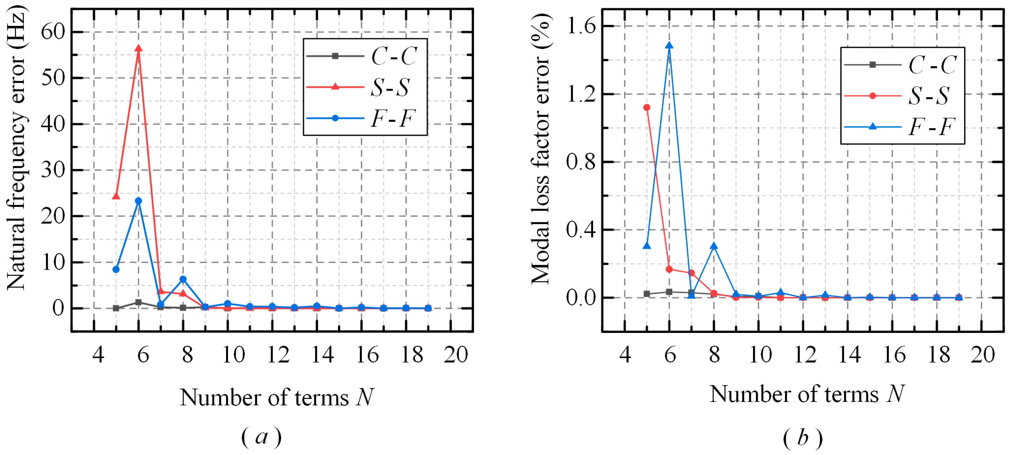
The purpose of this section is to verify the convergence and validity of the model. According to Ilanko et al.’s research [35], achieving convergence using the Gram–Schmidt orthogonal polynomial and artificial spring methods necessitates a high error truncation. To overcome this issue, a boundary function is used to determine the boundary conditions and reduce the value of N. In this paper, the convergence of the vibrational shape function is evaluated by calculating the error of the first N terms of the vibrational shape function. The results are presented in Figure 3. The computational results demonstrate that the natural frequency and modal loss factor gradually converge as the truncation number N increases. Specifically, when N = 10, the errors of both the natural frequency and the modal loss factor are less than 10−5, meeting the accuracy requirements of this paper. Hence, in subsequent work, a truncation number of N = 10 will be employed. The error of the natural frequency and modal loss factor is calculated in the following equation:
e f = | f m , k f m , k 1 | , e η = | η m , k η m , k 1 |
This paper employs F-F boundary conditions and sets ki = 0 (i = 1, 2, 3, 4) to ensure effective validation. The proposed method is verified by comparing the calculated parameters R = 0.0635 m, L= 0.502 m, h = 0.0635 m, E = 2.1 × 10¹¹ Pa, and μ = 0.28 with the results obtained by Zhang et al. [36] and the finite element method (FEM), respectively. The natural frequencies of the MRCS are obtained by substituting the calculated parameters into Equation (34), and the comparative verification results are presented in Table 1. The errors produced by all three methods are less than 5%, indicating that the proposed model is valid. Furthermore, the proposed method has a low computational cost as only the integration results need to be calculated in advance, and the integral calculation is separable. Hence, it can significantly reduce computational resource consumption and prevent the waste of resources. This saves much computation time, especially in the case of the high term number N.

3.2. Effect of the Preload State and Axial Boundary Conditions

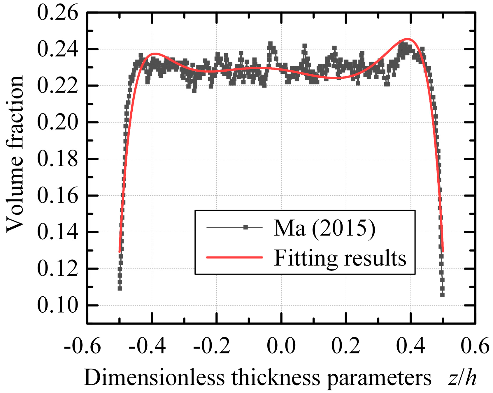
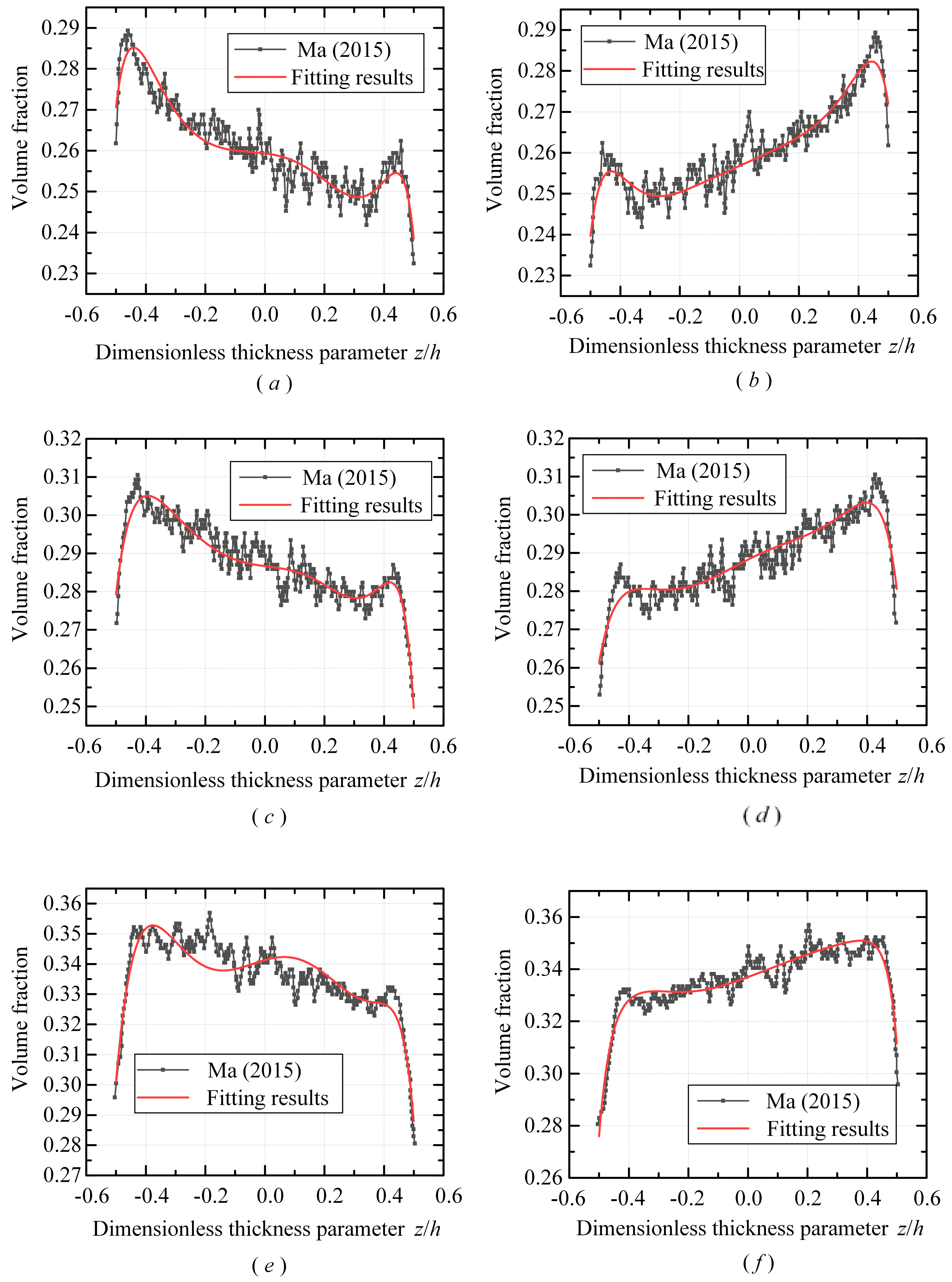
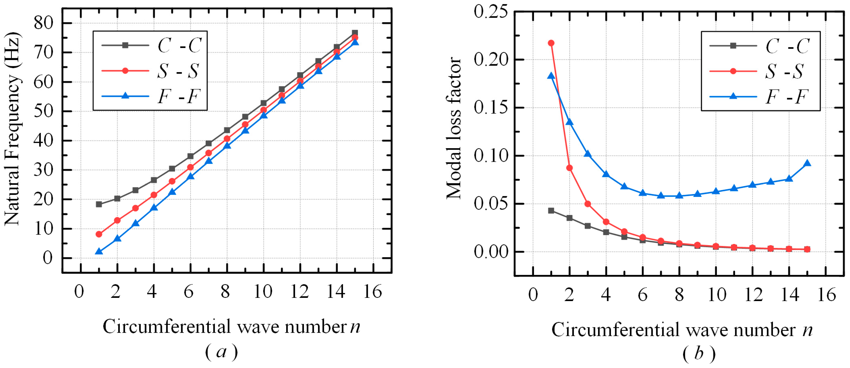
The proposed model is used in this section to calculate the intrinsic frequency and modal loss factor of the MRCS under different boundary conditions at both ends. The volume fractions utilized in the calculations were obtained from X-ray tomography tests conducted by Ma et al. [15], who provided volume fractions for different preload states. Pre-strain δ/h0 = 0, 0.8%, 1.6%, and 2.5% were used in this study to describe the pre-stressed state, where h0 is the thickness of the shell before deformation. The IHP model is demonstrated to be valid within the range of strain ε ≤ 2.5% by Ma et al., and all calculations in this paper fall within this valid range. The volume fraction fitting results for different pre-strain states are summarized in Table 2, and the fits obtained in this research are compared to the experimental results of Ma et al. [15], illustrated in Figure 4 and Figure 5. The resulting root mean square error has a mean value of 5 × 10⁻³, satisfying the requirements of this study. The material parameters of the MRCS are determined using the IHP model [12]: Ea = 4.437 MPa, Eb = 2.2069 Mpa, μ = 0.088, Ga = 1.1042 Mpa, Gb = 2.3617 Mpa, L = 20 R, h = 0.05 R, and k1 = k2 = 0. Since MR has a small Poisson’s ratio, which is close to zero with or without pre-compression [16], this paper ignores the variation of Poisson’s ratio and sets it to μ = 0.088. Finally, Figure 6 illustrates the intrinsic frequencies and modal loss factors of the MRCS without pre-compression under different boundary conditions at both ends.
In Figure 6, the intrinsic frequencies and modal loss factors of the MRCS with different boundary conditions are presented. Specifically, at low circumferential wave numbers, the inherent frequencies for different two-end boundary conditions vary. As the circumferential wave number increases, the inherent frequencies converge, indicating a weakening influence of two-end boundary conditions on the inherent frequencies. In contrast, the modal loss factor converges to different values based on the boundary conditions at both ends. With the increase of n, the damping and damping capacity of the MRCS under the C-C and S-S boundary conditions tend to be the same, while the MRCS under the F-F boundary conditions exhibits a different damping and damping capacity. Figure 7 demonstrates the effects of different pre-strain states for the same two-end boundary conditions on the natural frequency and modal loss factor of the MRCS. The findings reveal increasing pre-strain results in an increase in the natural frequency of the MRCS, while the modal loss factor exhibits a decreasing trend. This aligns with the expectation that the number of contact points of the wire inside the MRCS increases with a pre-strain, leading to a higher stiffness and natural frequency. Additionally, the percentage of dissipated energy within the MRCS decreases, contributing to a lower modal loss factor. Notably, the peak point of the modal loss factor under the F-F boundary condition shifts gradually to higher-order vibrations as the pre-displacement increases.
This paper presents a comparison between the natural frequencies and modal loss factors of the MRCS that have undergone internal and external pre-tensioning. Both types of shells were subjected to the same boundary conditions at both ends, and the comparison is presented in Table 3. The calculated results demonstrate that the volume fractions of the MRCS are different after internal and external pre-tensioning. Nevertheless, the natural frequencies and modal loss factors of MRCS are found to be nearly identical. This suggests that the radial preload force applied does not impact the natural frequency and modal loss factor of the MRCS.

3.3. Effect of the Pasternak Elastic Foundation

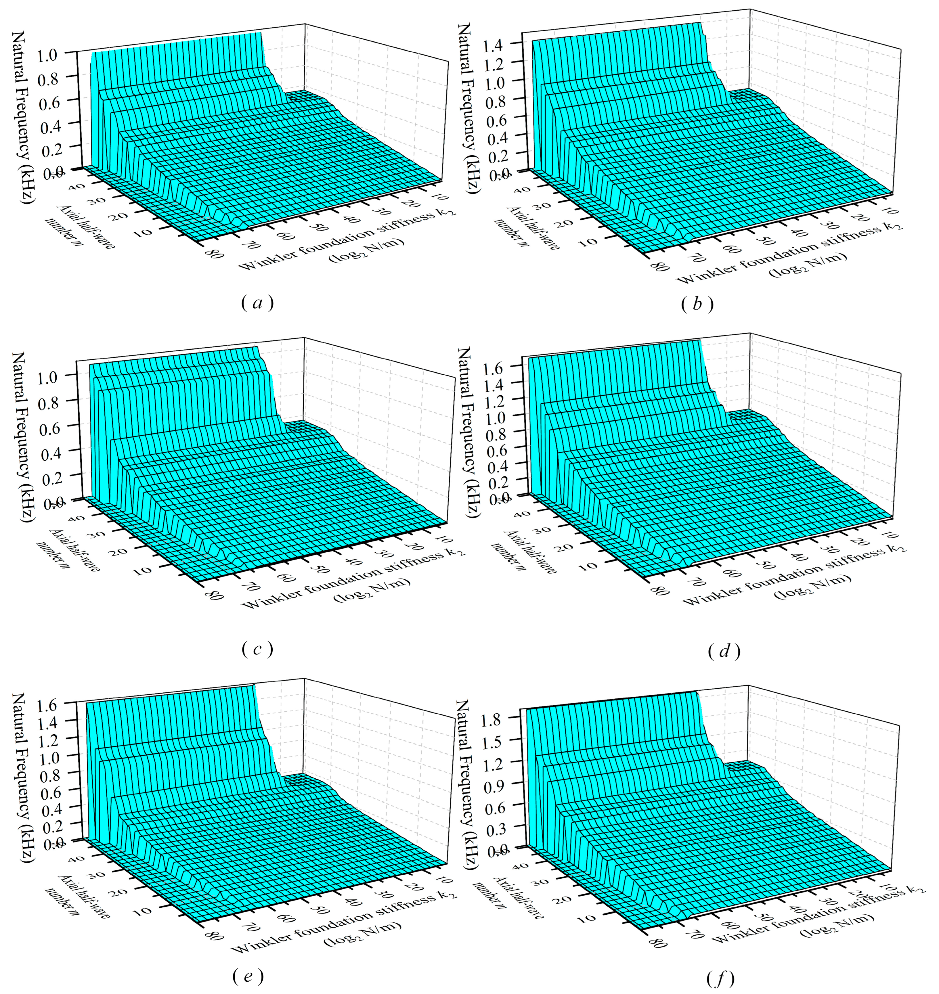
This section discusses the influence of the Winkler foundation stiffness ki (i = 1, 3) and Shear subgrade modulus kj (j = 2, 4) on the natural frequency and modal loss factor. The Pasternak elastic foundation is applied to the interior of the MRCS, resulting in k1 = k2 = 0, and the MRCS is in an internal pretension state. Conversely, when the Pasternak elastic foundation is applied externally to the MRCS, k3 = k4 = 0, and the MRCS is in an externally preloaded state. Figure 8 and Figure 9 illustrate the impact of k1 and k2 on the natural frequency of MRCS in the external support state. The results indicate that the natural frequency of MRCS increases with an increase in k1, with a more pronounced effect when k1 < 109 N/m. However, the effect of k2 on the natural frequency of MRCS is relatively weak. When m < 30, an increase in k2 leads to an increase in natural frequency, while when 30 < m < 35, the effect of k2 is similar to that of artificial spring technology. When k2 < 106, the shear deformation of the MRCS can be regarded as unconstrained. Conversely, when k2 > 109, the shear deformation of the MRCS is fixed. When 106 < k2 < 109, the Pasternak elastic foundation can be regarded as imposing arbitrary radial boundary conditions on the MRCS. It is worth noting that both k1 and k2 have effective ranges, and numerical instability will occur in the calculation if k1 and k2 are too high. Figure 10 compares the natural frequency and modal loss factors of the MRCS in internal and external bracing states. The results indicate that k1 and k3 have the same effect on the natural frequency and modal loss factor of the MRCS, while k2 and k4 have the same effect on the natural frequency and modal loss factor of the MRCS. With an increase in ki (i = 1, 2, 3, 4), the natural frequency increases, while the modal loss factor decreases and tends to be stable.

4. Validation and Discussion of the Results

In order to demonstrate the correctness and validity of the proposed model, a numerical simulation and experimental measurement of the vibration characteristics of the MRCS are carried out in this paper. The MR samples are manufactured from stainless steel alloy wires with a diameter of 0.12 mm. The mechanical properties of 304 stainless steel are shown in Table 4.
In the experiments in this paper, MRCSs are suspended by a soft rubber band in order to simulate the free boundary conditions at both ends of the MRCS, as shown in Figure 11a. Due to how the MRCS is almost free of forces in the horizontal direction, its boundary conditions can be approximately considered free in this direction. The force signal and the acceleration signal generated by the force hammer hitting the MRCS are collected by the force sensor and acceleration sensor and transmitted to the B&K data processing terminal for modal analysis. Finally, the natural frequency and the damping ratio of the MRCS are obtained by analyzing the obtained data through the B&K signal processing system.
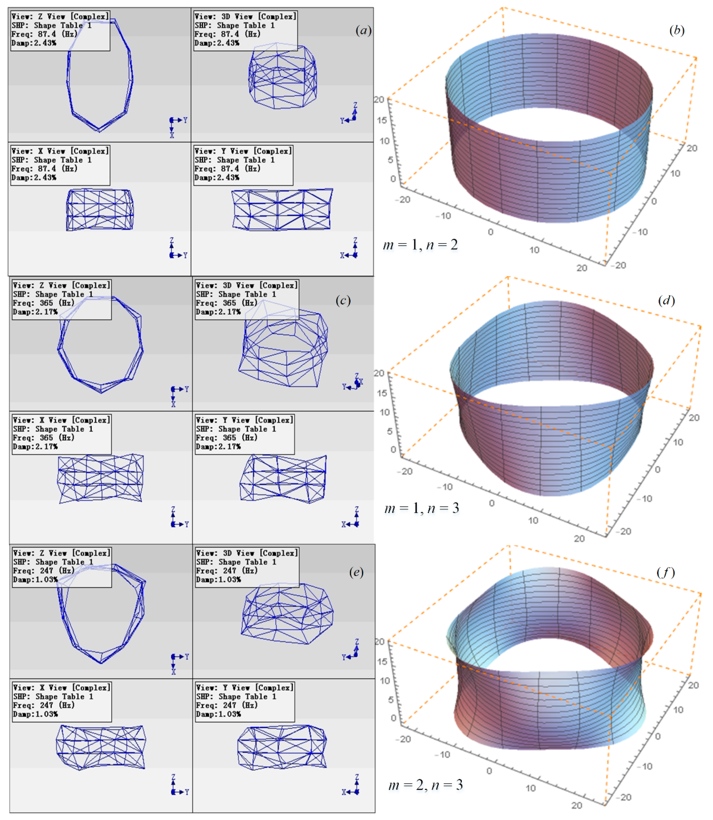
The experimental modeling work in this paper was carried out by the B&K data acquisition system, and the MRCSs were discretized into a polyhedral shell structure, as shown in Figure 11c. The characteristic parameters of the MRCSs are shown in Table 5. MRCSs are divided into nine groups of nodes in the circumferential direction and nine groups of nodes in the length direction. Table 6 shows the comparison between the theoretical values and the experimental results which were consistent, indicating that the calculated results are correct. The comparison of their modes is shown in Figure 12.

5. Conclusions

This paper analyzes the vibration characteristics of the MRCS using the Rayleigh–Ritz method and Gram–Schmidt orthogonal polynomials. The study discusses the effects of boundary conditions and preload states on the natural frequency and modal loss factor and verifies the convergence and validity of the model. The results of the study are as follows:
  • The boundary conditions at both ends have a significant impact on the natural frequency and modal loss factor of the MRCS. The C-C boundary condition has the highest natural frequency and damping ratio, while the F-F boundary condition has the lowest.
  • The Pasternak elastic foundation has a significant effect on the natural frequency and modal loss factor of the MRCS. In low-order modes, the natural frequency increases with increasing ki (i = 1, 2, 3, 4), and the modal loss factor decreases with increasing ki (i = 1, 2, 3, 4). In higher-order modes, the effect of ki (i = 1, 2, 3, 4) on the natural frequency and modal loss factor is the same as that of the artificial spring. Additionally, the radially applied position of the Pasternak elastic foundation does not affect the natural frequency and modal loss factor.
  • The preload displacement has a significant effect on the natural frequency and modal loss factor of the MRCS. The natural frequency increases with an increasing preload displacement, and the modal loss factor decreases with an increasing displacement. Furthermore, the effects of internal and external preload on the natural frequency and modal loss factor are the same.

Author Contributions

Conceptualization, methodology, investigation, software, formal analysis, and visualization, as well as writing the original draft, Y.B.; Providing resources, reviewing and editing the manuscript, and validating the data, P.D.; Managing data curation and assisting with investigation, K.F.; Supervising the project and managing resources, H.L. All authors have read and agreed to the published version of the manuscript.

Funding

This research received no external funding.

Conflicts of Interest

The authors declare no conflict of interest.

Nomenclature

hThe thickness of MRCS (m)δVariable Score Symbols (-)
RThe radius of the middle surface of MRCS (m)t, t1, t2Times, Starting moment, Ending moment (s)
LCylindrical shell length (m)ωRound Frequency(rad)
u, v, wDisplacement of the shell along x, θ, z direction (m)nCircumferential wave number (-)
ψx, ψθRotation angles normal to the direction of the x and θ axis (rad)maxial half-wave number (-)
a1, a2Lamé coefficient in the x, θ direction in the middle surface (-)δklKronecker constant (-)
R1,R2The radius of curvature in the x, θ direction in the middle surface (m)fNatural frequency of MRCS (Hz)
A1, A2Lamé coefficient along x, θ direction in cylindrical shell (-)ηThe modal loss factor of MRCS
nmNumber of screws of equivalent spring unit (-)βHalf cone angle of equivalent spring unit (rad)
EU/LEquivalent modulus of elasticity (MPa)η1, η2Normal strain loss factor and shear strain loss factor of MR
εx, εθNormal strain of shell along x, θ direction (-)NANumber of helix unit in the axial section of MRCS (-)
γ, γθz, γxzShear strain of the shell normal to the z-axis, x-axis and θ-axis (-)NLNumber of helix unit in length L of MRCS (-)
ACylindrical shell shaft cross-sectional area (m2)ρmRelative density of Metal-Rubber samples (%)
κx, κθThe slope of strain εx, εθ along the z-direction (-) ρ - Relative density of Metal-Rubber blanks (%)
E, EmYoung’s modulus of MRCS, metal wire (GPa)a, bLoad correction factor (-)
μPoisson’s ratio (-)αGuidance angle (rad)
ρThe density of MRCS (kg/m3)d, DWire diameter, Coil diameter (mm)
Ns, QsMembrane stresses (Pa)NOrder number of mode phase function (-)
MsMembrane moments (Pa·m)CSpring index of the helix unit (-)
KsTransverse shear correction factor (-)φ, φ - Inclination angle of the helix unit and its mean value (rad)
UeShell strain energy (N·m)rmolding ratio of MR (-)
TeShell kinetic energy (N·m)KTAxial stiffness of the helix unit (N/m)
μmPoisson’s ratio of MRKVTangential stiffness of the helix unit (N/m)

Appendix A

The individual coefficient matrices in Equation (34) can be expressed as follows:
K s s = ( K s s ( 11 ) 0 0 K s s ( 14 ) 0 0 K s s ( 22 ) 0 0 K s s ( 25 ) 0 0 K s s ( 33 ) 0 0 K s s ( 41 ) 0 0 K s s ( 44 ) 0 0 K s s ( 52 ) 0 0 K s s ( 55 ) )
K s s = ( 0 K s s ( 12 ) 0 0 K s s ( 15 ) K s s ( 21 ) 0 0 K s s ( 24 ) 0 0 0 0 0 0 0 K s s ( 42 ) 0 0 K s s ( 45 ) K s s ( 51 ) 0 0 K s s ( 54 ) 0 )
K s s = ( K s s ( 11 ) 0 0 K s s ( 14 ) 0 0 K s s ( 22 ) 0 0 K s s ( 25 ) 0 0 K s s ( 33 ) 0 0 K s s ( 41 ) 0 0 K s s ( 44 ) 0 0 K s s ( 52 ) 0 0 K s s ( 55 ) )
M s s = ( M s s ( 11 ) 0 0 M s s ( 14 ) 0 0 M s s ( 22 ) 0 0 M s s ( 25 ) 0 0 M s s ( 33 ) 0 0 M s s ( 41 ) 0 0 M s s ( 44 ) 0 0 M s s ( 52 ) 0 0 M s s ( 55 ) )
K s p r = 0 1 L 3 ( 0 0 0 0 0 0 0 0 0 0 0 0 h ( k 3 k 1 ) + 2 ( k 1 + k 3 ) R 2 R φ w φ w T 0 0 0 0 0 ( k 2 + k 4 ) φ φ x φ φ x T 0 0 0 0 0 ( k 2 + k 4 ) φ φ θ φ φ θ T ) d x
K s s ( 11 ) = 0 1 h 2 h 2 L 0 n 2 G 2 R 4 φ u φ u T d z d x
K s s ( 22 ) = 0 1 h 2 h 2 L 0 G K s 2 + E n 2 ( 1 + μ 2 ) 2 R 4 φ v φ v T d z d x
K s s ( 33 ) = 0 1 h 2 h 2 L 0 G K s 2 n 2 + E ( 1 + μ 2 ) 2 R 4 φ w φ w T d z d x
K s s ( 44 ) = 0 1 h 2 h 2 L 0 ( K s 2 R 4 G 2 R 4 ( R z ) 2 + n 2 z 2 G 2 R 4 ) φ φ x φ φ x T d z d x
K s s ( 55 ) = 0 1 h 2 h 2 L 0 G K s 2 R 2 + E n 2 z 2 ( 1 + μ 2 ) 2 R 4 φ φ θ φ φ θ T d z d x
K s s ( 41 ) = K s s ( 14 ) T = 0 1 h 2 h 2 L 0 n 2 z G 2 R 4 φ φ x φ u T d z d x
K s s ( 52 ) = K s s ( 25 ) T = 0 1 h 2 h 2 L 0 E n 2 z ( 1 + μ 2 ) G K s 2 R 2 R 4 φ φ θ φ v T d z d x
K s s ( 21 ) = K s s ( 12 ) T = 0 1 h 2 h 2 L 1 ( 1 + i η 1 ) μ ( 1 + μ 2 ) E 2 R 2 φ v φ u T x d z d x
K s s ( 51 ) = K s s ( 15 ) T = 0 1 h 2 h 2 L 1 z ( 1 + i η 1 ) μ ( 1 + μ 2 ) E 2 R 2 φ φ θ φ u T x d z d x
K s s ( 12 ) = K s s ( 21 ) T = 0 1 h 2 h 2 L 1 ( 1 + i η 2 ) G 2 R 2 φ u φ v T x d z d x
K s s ( 42 ) = K s s ( 24 ) T = 0 1 h 2 h 2 L 1 z ( 1 + i η 2 ) G 2 R 2 φ φ x φ v T x d z d x
K s s ( 24 ) = K s s ( 42 ) T = 0 1 h 2 h 2 L 1 z ( 1 + i η 1 ) μ ( 1 + μ 2 ) E 2 R 2 φ v φ φ x T x d z d x
K s s ( 54 ) = K s s ( 45 ) T = 0 1 h 2 h 2 L 1 z 2 ( 1 + i η 1 ) μ ( 1 + μ 2 ) E 2 R 2 φ φ θ φ φ x T x d z d x
K s s ( 15 ) = K s s ( 51 ) T = 0 1 h 2 h 2 L 1 z ( 1 + i η 2 ) G 2 R 2 φ u φ φ θ T x d z d x
K s s ( 45 ) = K s s ( 54 ) T = 0 1 h 2 h 2 L 1 z 2 ( 1 + i η 2 ) G 2 R 2 φ φ x φ φ θ T x d z d x
K s s ( 11 ) = 0 1 h 2 h 2 L 2 ( 1 + i η 1 ) ( 1 + μ 2 ) E φ u x φ u T x d z d x
K s s ( 41 ) = K s s ( 14 ) T = 0 1 h 2 h 2 L 2 z ( 1 + i η 1 ) ( 1 + μ 2 ) E φ φ x x φ u T x d z d x
K s s ( 22 ) = 0 1 h 2 h 2 L 2 ( 1 + i η 2 ) G φ v x φ v T x d z d x
K s s ( 52 ) = K s s ( 25 ) T = 0 1 h 2 h 2 L 2 z ( 1 + i η 2 ) G φ φ θ x φ v T x d z d x
K s s ( 33 ) = 0 1 h 2 h 2 L 2 K s 2 ( 1 + i η 2 ) G φ w x φ w T x d z d x
K s s ( 44 ) = 0 1 h 2 h 2 L 2 z 2 ( 1 + i η 1 ) ( 1 + μ 2 ) E φ φ x x φ φ x T x d z d x
K s s ( 55 ) = 0 1 h 2 h 2 L 2 z 2 ( 1 + i η 2 ) G φ φ θ x φ φ θ T x d z d x
M s s ( 11 ) = 0 1 h 2 h 2 L 2 ω 2 ρ   φ u φ u T d z d x
M s s ( 22 ) = 0 1 h 2 h 2 L 2 ω 2 ρ   φ v φ v T d z d x
M s s ( 33 ) = 0 1 h 2 h 2 L 2 ω 2 ρ   φ w φ w T d z d x
M s s ( 44 ) = 0 1 h 2 h 2 L 2 ω 2 z 2 ρ   φ φ x φ φ x T d z d x
M s s ( 55 ) = 0 1 h 2 h 2 L 2 z 2 ω 2 ρ   φ φ θ φ φ θ T d z d x
M s s ( 41 ) = M s s ( 14 ) T = 0 1 h 2 h 2 L 2 z ω 2 ρ   φ φ x φ u T d z d x
M s s ( 52 ) = M s s ( 25 ) T = 0 1 h 2 h 2 L 2 z ω 2 ρ   φ φ θ φ v T d z d x
G = [ ( G a G b ) V ( z ) + G b ] ( 1 + i η 2 )
E = [ ( E a E b ) V ( z ) + E b ] ( 1 + i η 1 )
L 0 = e i 2 t ω π ( R z ) 2 ( R + z )
L 1 = e 2 i t ω n π ( R 2 z 2 )
L 2 = 1 2 e 2 i t ω π ( R + z )
L 3 = e 2 i t ω π 2

References

  1. Liu, P.; He, G.; Wu, L. Uniaxial tensile stress–strain behavior of entangled steel wire material. Mater. Sci. Eng. A 2009, 509, 69–75. [Google Scholar] [CrossRef]
  2. He, G.; Liu, P.; Tan, Q. Porous titanium materials with entangled wire structure for load-bearing biomedical applications. J. Mech. Behav. Biomed. 2012, 5, 16–31. [Google Scholar] [CrossRef] [PubMed]
  3. Zarzour, M.; Vance, J. Experimental evaluation of a metal mesh bearing damper. J. Eng. Gas Turbines Power 2000, 122, 326–329. [Google Scholar] [CrossRef]
  4. Li, S.; Mao, C.; Li, H.; Zhao, Y. Mechanical properties and theoretical modeling of self-centering shape memory alloy pseudo-rubber. Smart Mater. Struct. 2011, 20, 115008. [Google Scholar] [CrossRef]
  5. Huang, M.; Fu, Y.; Qiao, X.; Chen, P. Investigation into Friction and Wear Characteristics of 316L Stainless-Steel Wire at High Temperature. Materials 2023, 16, 213. [Google Scholar] [CrossRef]
  6. Li, H.; Ren, Z.; Huang, J.; Zhong, S. Fretting wear evolution model of the metal filaments inside metal rubber. Wear 2022, 506, 204438. [Google Scholar] [CrossRef]
  7. Ren, Z.; Wen, G.; Guo, Z. Biomimetic high-intensity superhydrophobic metal rubber with anti-corrosion property for industrial oil–water separation. New J. Chem. 2019, 43, 1894–1899. [Google Scholar] [CrossRef]
  8. Ma, Y.; Zhang, Q.; Zhang, D.; Scarpa, F.; Liu, B.; Hong, J. Tuning the vibration of a rotor with shape memory alloy metal rubber supports. J. Sound Vib. 2015, 351, 1–16. [Google Scholar] [CrossRef]
  9. Yanhong, M.; Zhichao, L.; Hong, W.; Dayi, Z.; Jie, H. Theoretical and experimental steady-state rotordynamics of an adaptive air film damper with metal rubber. J. Sound Vib. 2013, 332, 5710–5726. [Google Scholar] [CrossRef]
  10. Wang, Y.; Zhang, Z.; Xue, X.; Zhang, L. Experimental investigation on enhanced mechanical and damping performance of corrugated structure with metal rubber. Thin Wall. Struct. 2020, 154, 106816. [Google Scholar] [CrossRef]
  11. Chegodaev, D.E.; OP, M.; EV, K. Design of Metal Rubber Components; National Defense Industry Press: Beijing, China, 2000; p. 258. [Google Scholar]
  12. Ma, Y.; Zhang, Q.; Zhang, D.; Scarpa, F.; Liu, B.; Hong, J. The mechanics of shape memory alloy metal rubber. Acta Mater. 2015, 96, 89–100. [Google Scholar] [CrossRef]
  13. Xue, X.; Ruan, S.; Bai, H.; Chen, X.; Shao, Y.; Lu, C. An enhanced constitutive model for the nonlinear mechanical behavior of the elastic-porous metal rubber. Mech. Mater. 2020, 148, 103447. [Google Scholar] [CrossRef]
  14. Ren, Z.; Shen, L.; Bai, H.; Pan, L.; Zhong, S. Constitutive model of disordered grid interpenetrating structure of flexible microporous metal rubber. Mech. Syst. Signal Process. 2021, 154, 107567. [Google Scholar] [CrossRef]
  15. Ma, Y.; Zhang, Q.; Wang, Y.; Hong, J.; Scarpa, F. Topology and mechanics of metal rubber via X-ray tomography. Mater. Design 2019, 181, 108067. [Google Scholar] [CrossRef]
  16. Zhang, D.; Scarpa, F.; Ma, Y.; Boba, K.; Hong, J.; Lu, H. Compression mechanics of nickel-based superalloy metal rubber. Mater. Sci. Eng. A 2013, 580, 305–312. [Google Scholar] [CrossRef]
  17. Do, V.T.; Pham, V.V.; Nguyen, H.N.; Tornabene, F. On the Development of Refined Plate Theory for Static Bending Behavior of Functionally Graded Plates. Math. Probl. Eng. 2020, 2020, 2836763. [Google Scholar] [CrossRef]
  18. Duc, D.H.; Thom, D.V.; Cong, P.H.; Minh, P.V.; Nguyen, N.X. Vibration and static buckling behavior of variable thickness flexoelectric nanoplates. Mech. Based Des. Struct. Mach. 2022, 1–29. [Google Scholar] [CrossRef]
  19. Duc, D.H.; Van Minh, P.; Tung, N.S. Finite element modelling for free vibration response of cracked stiffened FGM plates. Vietnam. J. Sci. Technol. 2020, 58, 119–129. [Google Scholar] [CrossRef]
  20. Wang, Y.Q.; Ye, C.; Zu, J.W. Vibration analysis of circular cylindrical shells made of metal foams under various boundary conditions. Int. J. Mech. Mater. Des. 2019, 15, 333–344. [Google Scholar] [CrossRef]
  21. Miao, X.; Li, C.; Jiang, Y. Free vibration analysis of metal-ceramic matrix composite laminated cylindrical shell reinforced by CNTs. Compos. Struct. 2021, 260, 113262. [Google Scholar] [CrossRef]
  22. Chen, W.; Luo, W.M.; Chen, S.Y.; Peng, L.X. A FSDT meshfree method for free vibration analysis of arbitrary laminated composite shells and spatial structures. Compos. Struct. 2022, 279, 114763. [Google Scholar] [CrossRef]
  23. Li, Z.; Zhong, R.; Wang, Q.; Qin, B.; Yu, H. The thermal vibration characteristics of the functionally graded porous stepped cylindrical shell by using characteristic orthogonal polynomials. Int. J. Mech. Sci. 2020, 182, 105779. [Google Scholar] [CrossRef]
  24. Rachid, A.; Ouinas, D.; Lousdad, A.; Zaoui, F.Z.; Achour, B.; Gasmi, H.; Butt, T.A.; Tounsi, A. Mechanical behavior and free vibration analysis of FG doubly curved shells on elastic foundation via a new modified displacements field model of 2D and quasi-3D HSDTs. Thin Wall. Struct. 2022, 172, 108783. [Google Scholar] [CrossRef]
  25. Qin, B.; Wang, Q.; Zhong, R.; Zhao, X.; Shuai, C. A three-dimensional solution for free vibration of FGP-GPLRC cylindrical shells resting on elastic foundations: A comparative and parametric study. Int. J. Mech. Sci. 2020, 187, 105896. [Google Scholar] [CrossRef]
  26. Duc, N.D.; Tuan, N.D.; Tran, P.; Dao, N.T.; Dat, N.T. Nonlinear dynamic analysis of Sigmoid functionally graded circular cylindrical shells on elastic foundations using the third order shear deformation theory in thermal environments. Int. J. Mech. Sci. 2015, 101, 338–348. [Google Scholar] [CrossRef]
  27. Johnson, C.D.; Kienholz, D.A. Finite Element Prediction of Damping in Structures with Constrained Viscoelastic Layers. Aiaa J. 1982, 20, 1284–1290. [Google Scholar] [CrossRef]
  28. Ma, B.; He, J. A finite element analysis of viscoelastically damped sandwich plates. J. Sound Vib. 1992, 152, 107–123. [Google Scholar] [CrossRef]
  29. Yamaguchi, T.; Kurosawa, Y.; Enomoto, H. Damped vibration analysis using finite element method with approximated modal damping for automotive double walls with a porous material. J. Sound Vib. 2009, 325, 436–450. [Google Scholar] [CrossRef]
  30. Qin, Z.; Chu, F.; Zu, J. Free vibrations of cylindrical shells with arbitrary boundary conditions: A comparison study. Int. J. Mech. Sci. 2017, 133, 91–99. [Google Scholar] [CrossRef]
  31. Qu, Y.; Hua, H.; Meng, G. A domain decomposition approach for vibration analysis of isotropic and composite cylindrical shells with arbitrary boundaries. Compos. Struct. 2013, 95, 307–321. [Google Scholar] [CrossRef]
  32. Xue, Y.; Jin, G.; Zhang, C.; Han, X.; Chen, J. Free vibration analysis of functionally graded porous cylindrical panels and shells with porosity distributions along the thickness and length directions. Thin Wall. Struct. 2023, 184, 110448. [Google Scholar] [CrossRef]
  33. Yang, S.W.; Hao, Y.X.; Zhang, W.; Yang, L.; Liu, L.T. Buckling and free vibration of eccentric rotating CFRP cylindrical shell base on FSDT. Appl. Math. Model. 2021, 95, 593–611. [Google Scholar] [CrossRef]
  34. CAO, F. Research on Effects of Loading Amplitude on Fatigue Life of Metal Rubber Material. China Mech. Eng. 2013, 24, 671. [Google Scholar]
  35. Ilanko, S.; Monterrubio, L.; Mochida, Y. The Rayleigh-Ritz Method for Structural Analysis; John Wiley & Sons: Hoboken, NJ, USA, 2014; p. 254. [Google Scholar]
  36. Zhang, W.; Fang, Z.; Yang, X.D.; Liang, F. A series solution for free vibration of moderately thick cylindrical shell with general boundary conditions. Eng. Struct. 2018, 165, 422–440. [Google Scholar] [CrossRef]
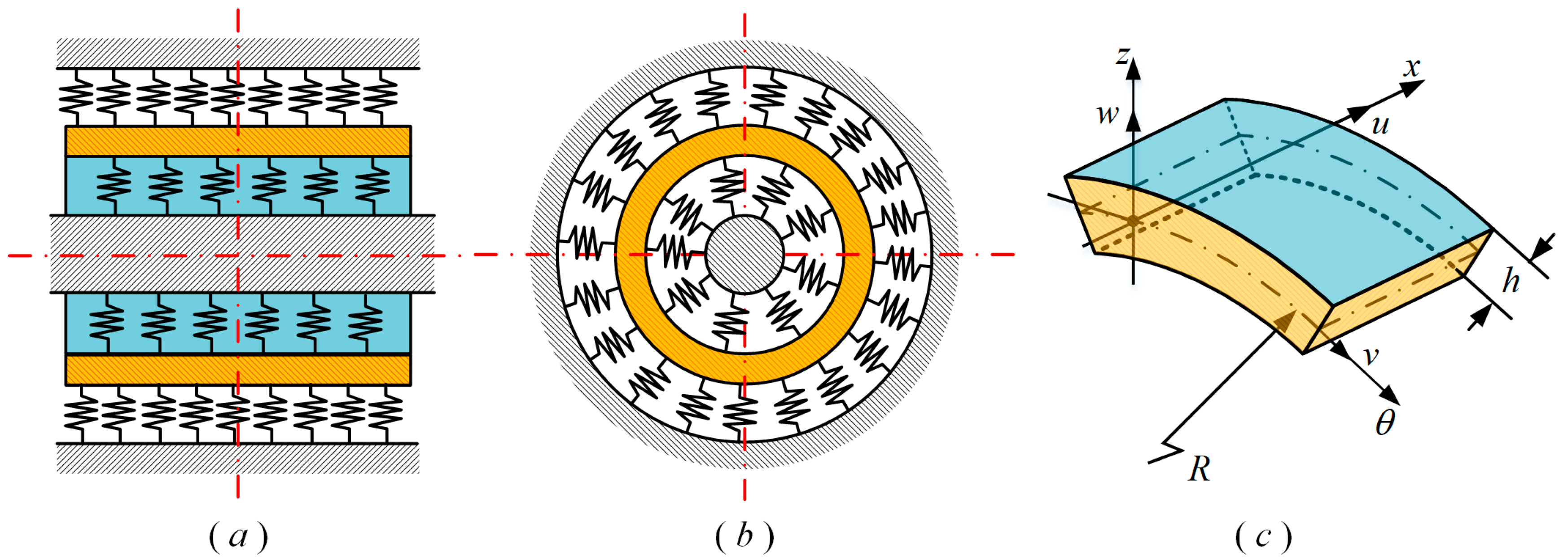
Figure 1. The structure and cells of the MRCS: (a) Axial cross section; (b) Radial section; (c) Coordinate system.
Applsci 13 06085 g001
Figure 2. Equivalent viscoelastic cell and arrangement of metal coils: (a) Cell structure of IHP model; (b) arrangement direction of IHP model in MR.
Applsci 13 06085 g002
Figure 3. Error of the natural frequency and modal loss factor: (a) convergence of natural frequencies; (b) convergence of the modal loss factor.
Applsci 13 06085 g003
Figure 4. Volume fraction distribution of the MR without pre−tensioning.
Applsci 13 06085 g004
Figure 5. Volume fraction distribution within MR at different preload states: (a,b) 0.8% internal preload and 0.8% external preload; (c,d) 1.6% mm internal preload and 1.6% mm external preload; (e,f) 0.25% mm internal preload and 2.5% mm external preload.
Applsci 13 06085 g005
Figure 6. The natural frequencies and modal loss factors of the MRCS under various two-end boundary conditions in the un-preloaded state (m = 1): (a) natural frequency; (b) modal loss factor.
Applsci 13 06085 g006
Figure 7. Natural frequencies and modal loss factors of a pre-tensioned MRCS under different boundary conditions (m = 1): (ac) the natural frequencies under C-C, S-S, and F-F boundary conditions; (df) the modal loss factors under C-C, S-S, and F-F boundary conditions.
Applsci 13 06085 g007
Figure 8. The effect of the Pasternak elastic foundation on the natural frequency and modal loss factor of the MRCS subjected to external preload (n = 1): (a,c,e) the influence of k1 on the boundary conditions of C-C, S-S, and F-F without preloading; (b,d,f) the influence of k1 under different preloading conditions at C-C boundary conditions.
Applsci 13 06085 g008
Figure 9. The effect of the Pasternak elastic foundation on the natural frequency and modal loss factor of the MRCS subjected to external preload (n = 1): (a,c,e) the influence of k2 on the boundary conditions of C-C, S-S, and F-F without preloading; (b,d,f) the influence of k2 under different preloading conditions at C-C boundary conditions.
Applsci 13 06085 g009
Figure 10. Effect of ki (i =1, 2, 3, 4) on the natural frequency and modal loss factor of the MRCS under 0.8% preload (m = 2, n = 1): (a) Effect of k1 and k3 on the natural frequency; (b) Effect of k1 and k3 on the modal loss factor; (c) Effect of k2 and k4 on the natural frequency; (d) Effect of k2 and k4 on the modal loss factor.
Applsci 13 06085 g010
Figure 11. MRCS and B&K analysis system: (a) modal test system; (b) hammer test of MRCS; (c) test model of B&K system.
Applsci 13 06085 g011
Figure 12. Comparison of theoretical and experimental vibration patterns of the MRCS: (a,b) n = 1, m = 2; (c,d) n = 1, m = 3; (e,f) n = 3, m = 2.
Applsci 13 06085 g012
Table 1. Validation of method validity.
VibrationPresentZhang [36]FEM
Parameters
m = 1, n = 2269.108268.49269.71
m = 2, n = 2270.855272.58276.95
m = 1, n = 3760.599758.3765.17
m = 2, n = 3774.53770.67762.721
m = 1, n = 41456.99--1473.5
m = 2, n = 41459.04--1483.3
Table 2. Fitting coefficients for the volume fraction of the MR under different preload conditions.
CoefficientInternal PreloadExternal Preload
0.8%1.6%2.5%0.8%1.6%2.5%
a10.25930.28670.34130.25580.28830.3370
a2−0.0092−0.01050.02750.01400.03940.0425
a3−0.06750.0221−0.13130.1344−0.03690.0272
a4−0.4254−0.5379−0.96560.2838−0.1799−0.1885
a50.43852.77112.9038−1.42291.38680.3617
a61.47085.3331−0.3238−0.8294−2.8985−3.6424
a74.2736−0.34951.2461−2.65170.85500.4057
a81.33570.999111.6435−2.1848−5.26411.5481
a9−10.9707−0.4705−10.265958.38572.60075.7922
a100.21582.4878−39.4096−9.59837.33981.4243
a110.7160−87.9092−45.808733.6653−19.33243.4407
a12−30.8714−85.83141.202595.12768.7059−0.3547
a13−164.4423−5.9095−7.2920−5.0656−32.2820−32.8691
a14−0.70372.1150−40.9135−88.8018−68.1837−17.7638
a150.2467−3.4719−4.3433−2820.63770.93871.2630
a162.13010.96191.44755.4057−1.7299−123.6476
a1710.38651.90553.26112.001415.4294−2396.1895
Table 3. Validation of method validity (m = 1).
PreloadnNatural FrequencyModal Loss Factor
C-CS-SF-FC-CS-SF-F
Internal preload1 37.342 18.182 4.502 0.052 0.208 0.163
2 45.455 32.393 12.896 0.140 0.262 0.153
3 54.907 45.920 22.743 0.215 0.281 0.122
4 60.380 53.575 32.947 0.188 0.265 0.098
5 67.262 62.236 43.175 0.162 0.226 0.084
6 75.153 71.428 53.338 0.138 0.186 0.076
7 83.731 80.917 63.425 0.118 0.152 0.072
8 92.774 90.595 73.447 0.100 0.125 0.072
9 102.137 100.406 83.412 0.086 0.104 0.074
10 111.725 110.319 93.322 0.074 0.087 0.077
External preload1 37.341 18.180 4.500 0.052 0.208 0.163
2 45.451 32.388 12.893 0.140 0.262 0.153
3 54.904 45.916 22.738 0.215 0.281 0.122
4 60.376 53.570 32.941 0.188 0.265 0.098
5 67.256 62.229 43.167 0.162 0.226 0.084
6 75.145 71.419 53.328 0.138 0.186 0.076
7 83.721 80.906 63.414 0.118 0.152 0.072
8 92.762 90.582 73.435 0.100 0.125 0.072
9 102.123 100.392 83.398 0.086 0.104 0.074
10 111.709 110.303 93.306 0.074 0.087 0.077
Table 4. Mechanical properties of stainless steel alloy wire.
GradesYield Strength
(N/mm2)
Young’s Modulus
(Gpa)
Density
(kg/m3)
Poisson’s Ratio
06Cr19ni1020519379300.285
Table 5. Characteristic parameters of MRCS samples.
Characteristic ParametersNumerical Value
Diameter of metal wire (mm)0.3
Metal coil diameter (mm)3
Density (kg/m3)3172
Young’s modulus (GPa)5.2 × 10⁶
Loss factor (%)22.609
Shell thickness (mm)1.5 × 10⁻²
Cylindrical shell diameter (mm)6.85 × 10⁻²
Cylindrical shell length (mm)6.20 × 10⁻²
Table 6. Comparison of experimental results.
Vibration Type ParametersNatural FrequencyDamping Ratio
Theoretical Value (Hz)Experimental Value (Hz)Error (Hz)Theoretical Value (%)Experimental Value (%)Error (%)
m = 1, n = 288.385.5122.790.7381.080.342
m = 3, n = 3248235.05812.9421.3891.030.359
m = 2, n = 4449.779452.3442.5652.321.720.6
m = 4, n = 4459.2634611.741.81.40.4
Disclaimer/Publisher’s Note: The statements, opinions and data contained in all publications are solely those of the individual author(s) and contributor(s) and not of MDPI and/or the editor(s). MDPI and/or the editor(s) disclaim responsibility for any injury to people or property resulting from any ideas, methods, instructions or products referred to in the content.