Article

The Effects of Forming Angle on the Geometry Accuracy and Mechanical Properties of Al-Li Alloy Truncated Pyramids by Single Point Incremental Forming

1
Light Alloy Research Institute, Central South University, Changsha 410083, China
2
State Key Laboratory of Precision Manufacturing for Extreme Service Performance, Central South University, Changsha 410083, China
*
Author to whom correspondence should be addressed.
Appl. Sci. 2023, 13(10), 6144; https://doi.org/10.3390/app13106144
Submission received: 12 April 2023 / Revised: 15 May 2023 / Accepted: 16 May 2023 / Published: 17 May 2023
(This article belongs to the Section Mechanical Engineering)

Abstract

:
In this study, single point incremental forming (SPIF) of Al-Li alloy sheets under different forming angles are studied via both experimental methods and numerical simulations. The effect of different forming angle on the geometric accuracy of SPIFed Al-Li component is studied. The simulation results show that the higher the forming angle, the lower the stress at the corner, leading to better geometrical accuracy, which is also experimentally validated. It is also found that high forming angle leads to better mechanical properties of the SPIFed Al-Li alloy component.

1. Introduction

Sheet metal forming has become an important manufacturing process for various industrial applications. Many components are obtained by stretching, shearing and bending, etc. However, each of these forming methods requires dedicated and highly specialized equipment to achieve. As a result, these traditional sheet metal forming processes are expensive and time consuming to manufacture components. In order to meet the modern industrial demand for low cost and low cycle time, SPIF is increasingly adapted in the engineering field. SPIF is a die-less, flexible and rapid forming process. During the forming process, a hemi-spherical tool head is incrementally moving into the desired shape along a pre-defined trajectory forming path. Compared with traditional forming processes, SPIF deforms the material under severe plastic strain as a result of local deformation and through-thickness shearing. SPIF is particularly suitable for the rapid making of prototype products and components in small quantities with high demand on geometry accuracy [1,2,3,4,5]. For example, recent reports on the making of Al-Cu alloy truncated pyramid component by SPIF have attracted a lot attention due to its advantages on improving geometry accuracy [6].
In terms of material selection for these components, Al-Li alloys with low density, high elastic modulus and high specific strength, are gradually replacing Al-Cu alloys for rocket launchers and many other aerospace components [7,8,9,10,11]. Hence, it is of great interest to investigate the compatibility of SPIF with Al-Li alloys. However, Al-Li alloy is famous for its complex deformation behaviors and is known to have low formability at room temperature. Compared to Al-Cu alloy, it is easy to produce high internal stresses and microstructural defects during deformation of Al-Li alloy, which cause geometry distortion and cracking of the components during subsequent quenching [12,13,14]. Increasing the forming temperature during SPIF is advantageous for material flow, which improves the forming limit and reduces residual stresses. However, to date there have been no detailed reports on optimal processing parameters for SPIF on Al-Li alloys.
In die-less forming processes, geometric accuracy is one of the most important indicators to evaluate the formability and integrity of the components. In recent years, a large number of scholars have conducted a lot of research work on the formability aspects of SPIF. Liu [15] concluded that sheet thickness is the most important influencing factor on formability. The possible reason is the s with different thickness can lead to different surface strains during forming. At the same time, feed rate and tool diameter have little influence on the overall surface roughness. Petek [16] found that forming tool rotation and lubrication state have little effect on stress but have a significant effect on formability. Jawale [17] found that mineral oil can effectively improve surface roughness and can form forces and friction. Hamilton [18] investigated the effect of feed rate and rotation speed of forming tool on roughness and developed a mathematical model to effectively predict creases. Shi [14] concluded that good formability can be obtained to the maximum extent by designing the trajectory of the forming tool as a spiral trajectory route. Specifically, the forming angle is reported to be a key factor to achieve good geometry accuracy of the SPIFed component. Studies show that the larger the forming angle, the smaller the forming force [19,20,21]. This is because the increase in angle can reduce the stiffness of the sheet. The formed components have better formability. Khan [6] reported the geometric accuracy and residual stresses of truncated pyramid component made of AA2219 age-hardened alloy. The yield strength of the initial sheet was found to have a significant effect on the geometric accuracy. Secondly, solution treatment, SPIF and age-hardening can improve very high geometric accuracy. In contrast, solution treatment, age-hardening and SPIF have the largest residual stresses, which cause the largest geometric accuracy errors. This also shows that higher residual stresses lead to higher geometric accuracy errors. The results of Mohammadi’s study showed that the strength and properties of the material were difficult to improve after annealing treatment of AA2024 aluminum alloy sheet without any subsequent heat treatment [22]. Kumar [23] reported that the forming performance increases with the decrease of forming angle, and the combination of reducing step size and forming angle can significantly improve the forming performance. The forming angle of SPIF is more significant for the formability of Al-Cu alloy sheet than parameters such as tool shape, tool diameter, sheet thickness, and tool speed, but this has not yet been tested in SPIF of Al-Li alloy made component, which is more complex system for its rich secondary phase particles.
As is commonly understood, there are four methods to improve strength: fine crystallization strengthening, deformation strengthening, solution strengthening and precipitation strengthening. Al-Li alloy belongs to precipitation strengthening aluminum alloy, and good precipitation strengthening effect can be obtained through appropriate heat treatment process. In order to understand the precipitation behavior of Al-Li alloy, many scholars have conducted extensive basic research on the relationship between mechanical properties and microstructure [24,25,26]. Much of the literature explains that the strength improvement of aluminum lithium alloy mainly relies on the precipitation phase such as θ phase and T1 phases, which can obtain better strengthening effect. The reason is that T1 phase has a particularly high aspect ratio, and better shear resistance than other precipitated phases relative dislocations, which can better improve the work hardenability [27,28].
Based on the aforementioned research, we understand that there is a significant lack of studies focused on improving the geometric accuracy of Al-Li alloy sheets through SPIF without sacrificing high-performance components. Therefore, further research on SPIF of Al-Li alloys is necessary. This work investigates the effect of forming angle on the geometry accuracy and performance of the SPIFed Al-Li alloy sheet via numerical simulation and experimental validations.

2. Methodology

2.1. Materials

The material used in this study is a 3 mm-thick Al-Li alloy sheet with following chemical composition: Al-4.1%Cu-0.9%Li-0.28%Mg-0.26%Ag-0.13%Zr-0.04%Mn (wt.%). The sheet are sanded with #1000 sandpaper for eliminating surface processing defects and reducing surface roughness.

2.2. Age Hardening Cycle

Figure 1 shows an experimental processing diagram for Al-Li alloy. The thin sheet was heated in heating furnace to 200 °C for 15 min, then quickly transferred to the machining center for hot SPIF. The best square tapered parts were obtained and then subjected to solution treatment and T8 aging treatment. The artificial aging temperature was 160 °C and the peak aging times were 35 h, 32 h and 84 h at each forming angle. After T8 aging treatment, tensile specimens were cut in the wall area of the truncated pyramid component along the direction of the forming toll movement. Subsequently, a room temperature tensile test was conducted on a CSS-44100 test tensile machine at a speed of 2 mm/min to obtain load displacement data until the fracture point. Take three samples from each group of experiments for tensile specimen testing. The tensile specimens were spaced 30 mm and 6 mm wide. Electron backscatter diffraction (EBSD) and transmission electron diffraction microscopy (TEM, Tecnai G2 F20) observation specimens were obtained from the wall region. Before conducting EBSD detection on the grain structure of the wall, the sample surface was placed in an ethanol solution and subjected to electrolytic polishing at −15 °C for 6 s at a voltage of 16 V. The scanning step size of EBSD data is 1 μ m . The EBSD data were analyzed using channel-5 analysis software. Grain boundaries with different misorientations are designated as follows: low-angle grain boundaries (LAbs) from 2° to 15° and high-angle grain boundaries (HABs) greater than 15°. The above two types of boundaries are separately represented by white and black lines, respectively. The sample for TEM observation was mechanically ground to a thickness of approximately 80 μ m . Subsequently, TEM samples were prepared by a twin-jet electro-polishing device in a solution containing 75% methanol and 25% nitric acid (volume fraction) at −30 to −20 °C with a voltage of 15–30 V and a current of 70–95 mA.

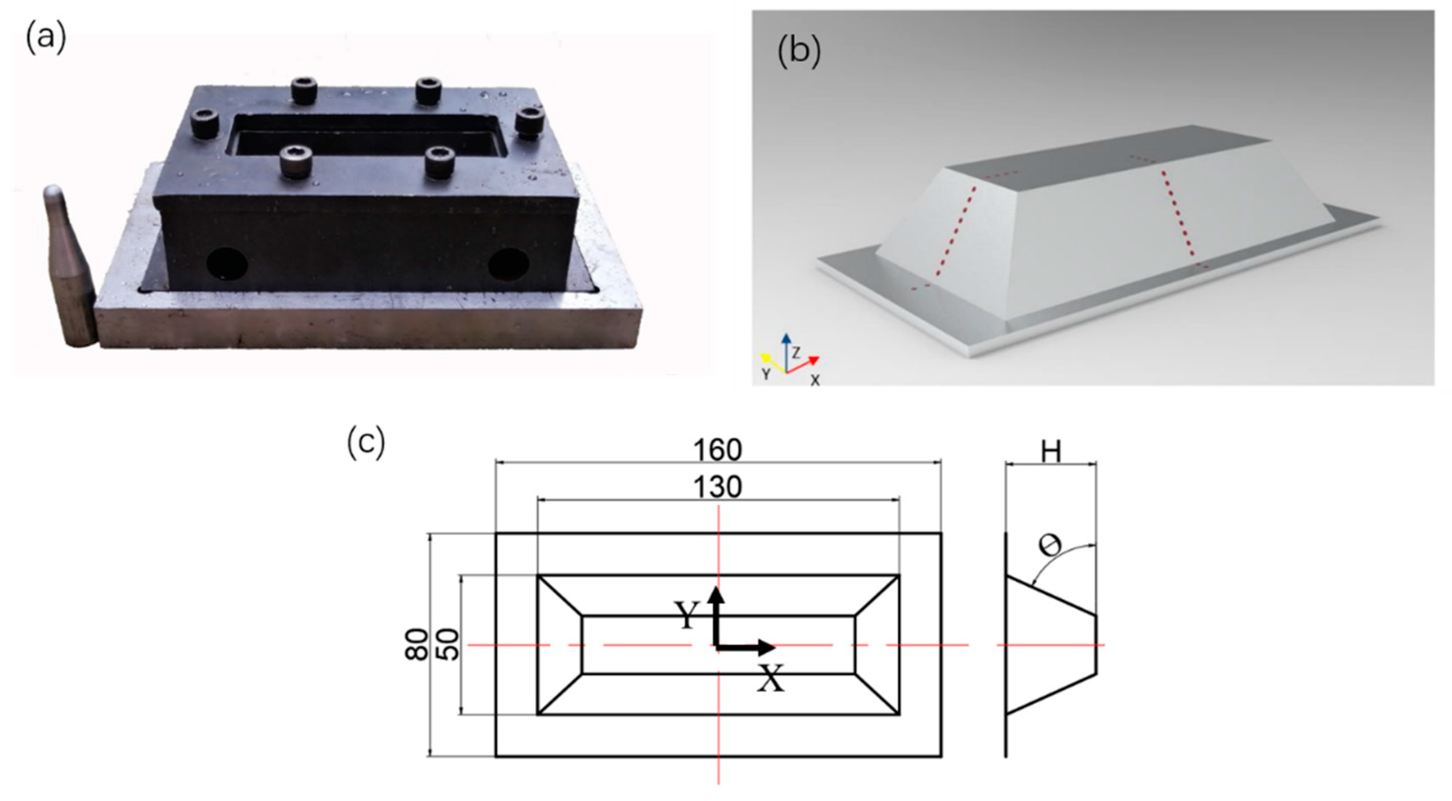
2.3. Experiment Setup and Process Parameters

The SPIF experiment is performed on a CNC machining equipment. The forming tool has a radius of 5 mm and uses H12 steel material which has good wear resistance, and the mold is shown in Figure 2a. Engine oil was used as lubrication. The thin sheet is completely clamped around its perimeter, and SPIF is performed following set program forming a truncated pyramid component. The spiral tool forming trajectory of is programmed using Unigraphics NX software. Following the spiral trajectory, the tool gradually pushes the sheet towards the depth of the truncated pyramid component.
As shown in Figure 2b. geometric contour measurements were taken in X and Y directions of the truncated pyramids component, and the wall thickness at the corresponding position was calculated. To quantify the geometric accuracy error, the measurement coordinates are recorded and plotted in the CAD software and used to evaluate the error between the actual contour and the design contour. The red dotted lines represent the positions for wall thickness measurement in the X and Y directions. The uniformity of wall thickness is obtained by calculating the standard deviation of the measured values. The smaller the value, the more uniform the thickness; vice versa indicates poorer uniformity. As shown in Figure 2c, the edge length of the thin sheet is 160 × 80 mm, the forming area is 130 × 50 mm, θ represents the forming angle and H represents the forming depth.

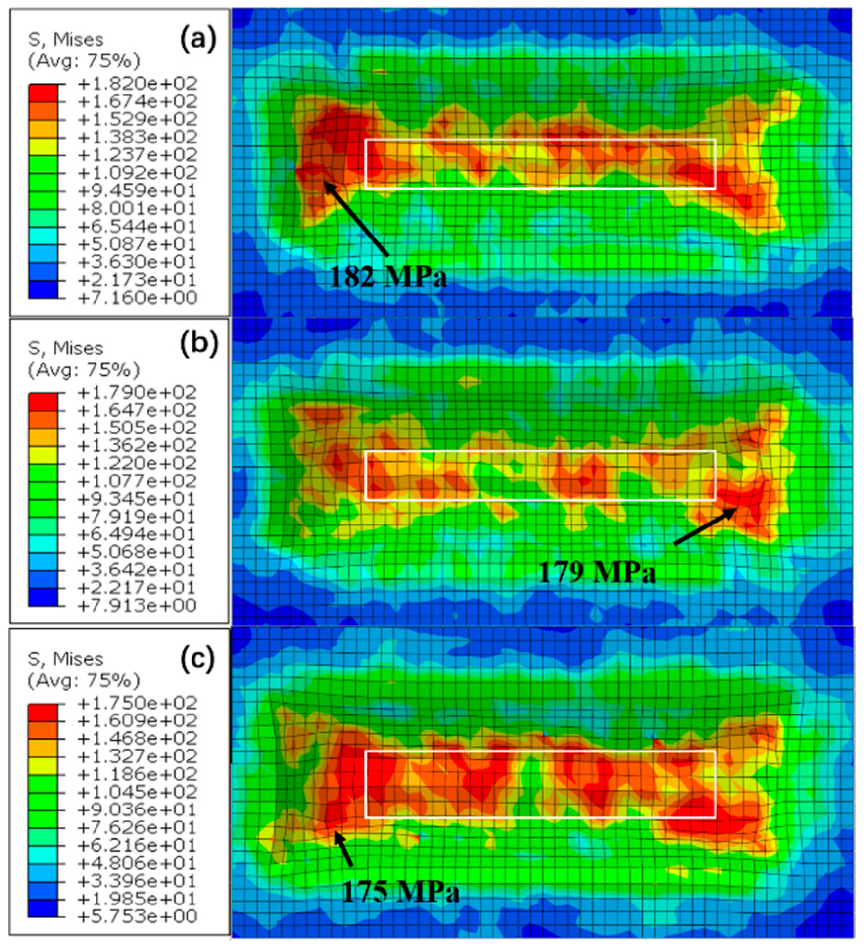
3. Numerical Simulation

Commercial finite element simulation software ABAQUS is used for SPIF numerical simulation. The simulation was carried out using ABAQUS/Explicit. The thin sheet is set as a solid element. Forming tool, fixture and die are set as a rigid body. As shown in Figure 3 below, the stress-strain curve of Al-Li alloy at 200 °C is input into the material properties. Other material parameters are shown in Table 1. The coefficient of friction between the tool head and the sheet is set to 0.1. An eight-node linear hexahedral cell with reduced integration (C3D8R) was used for meshing. Grid sweep method is used for meshing the thin sheet, a global size of 2 is set and adaptive meshing is performed. The coordinate of the forming tool path is extracted according to the set trajectory route in Unigraphics NX software, the coordinates of the forming tool path are extracted and imported into ABAQUS software.
In order to verify the accuracy of the model, a comparison of the wall thickness and contour accuracy between simulated truncated pyramid component and the experimentally formed pyramid cone component was conducted. As shown in Figure 4, the SPIF forming depth was set to 20 mm, the deformation temperature was at 200 °C, the forming angle was set as 50°, the rotation speed was at 600 rpm, the feed rate was 1200 mm/min, and the forming tool head radius was 5 mm.
From Figure 5, it can be seen that the contour accuracy and thickness distribution of experimentally formed truncated pyramid component is basically consistent with the simulation results. The main deviation is at the bottom area where material accumulates gradually during the SPIF process, leading to an increase in thickness and geometric errors.

4. Results and Discussion

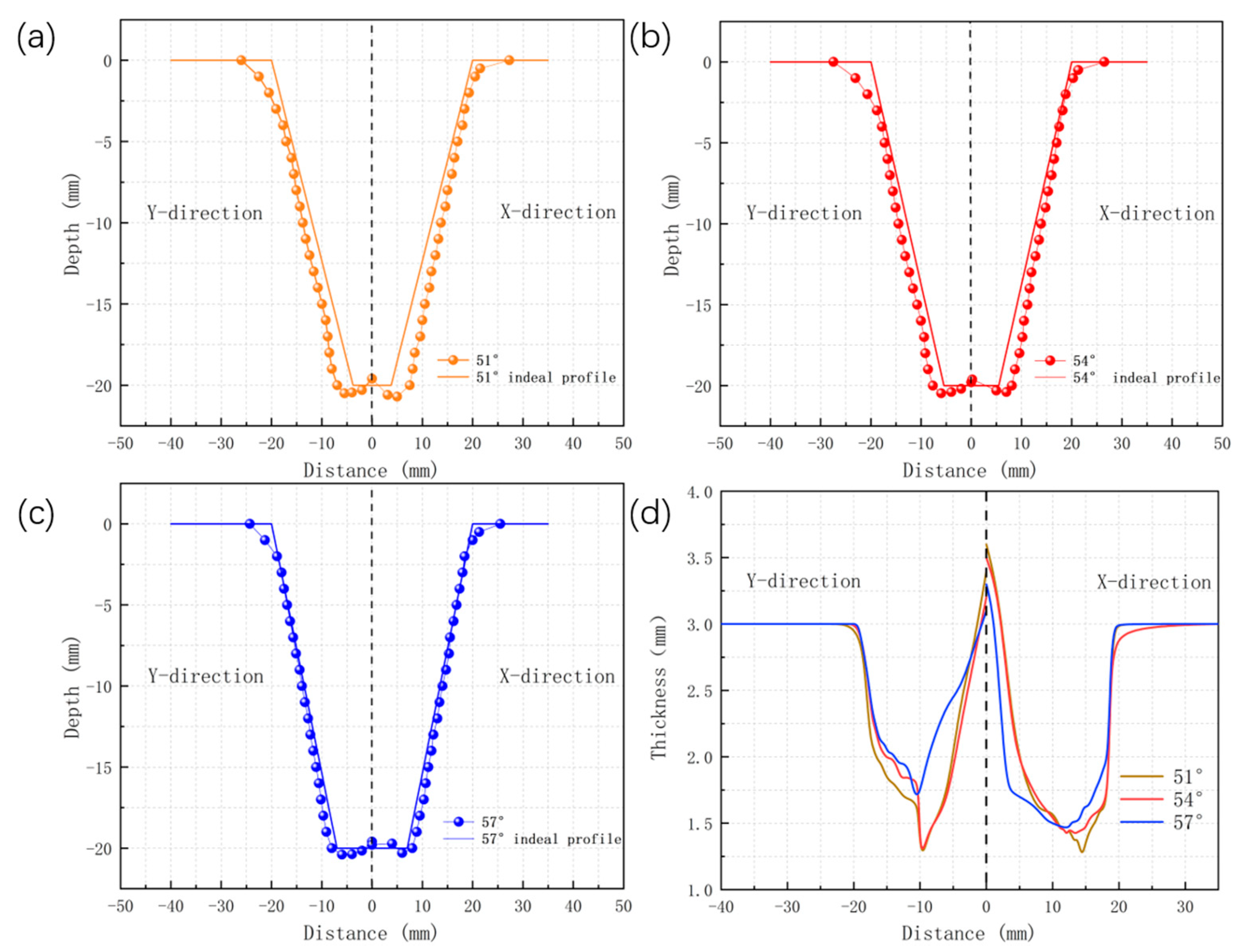
4.1. Effect of Forming Angles on Geometric Accuracy

Figure 6 demonstrates the maximum thinning rate and standard deviation of wall thickness of truncated pyramids component under different forming angles. When the forming angle is 51°, the maximum thinning rate and standard deviation are 58.66% and 0.220 respectively. As the forming angle increases, the maximum thinning rate and standard deviation gradually decrease. This indicates that with larger forming angles, the deformation is more uniform. The contact area between the forming tool and the thin sheet decreases as the forming angle increases, which leads to a point-by-point reduction in the rolling effect of the forming tool on the thin sheet during the forming process [16,19]. This is also the reason why larger forming angles result in more uniform deformation.

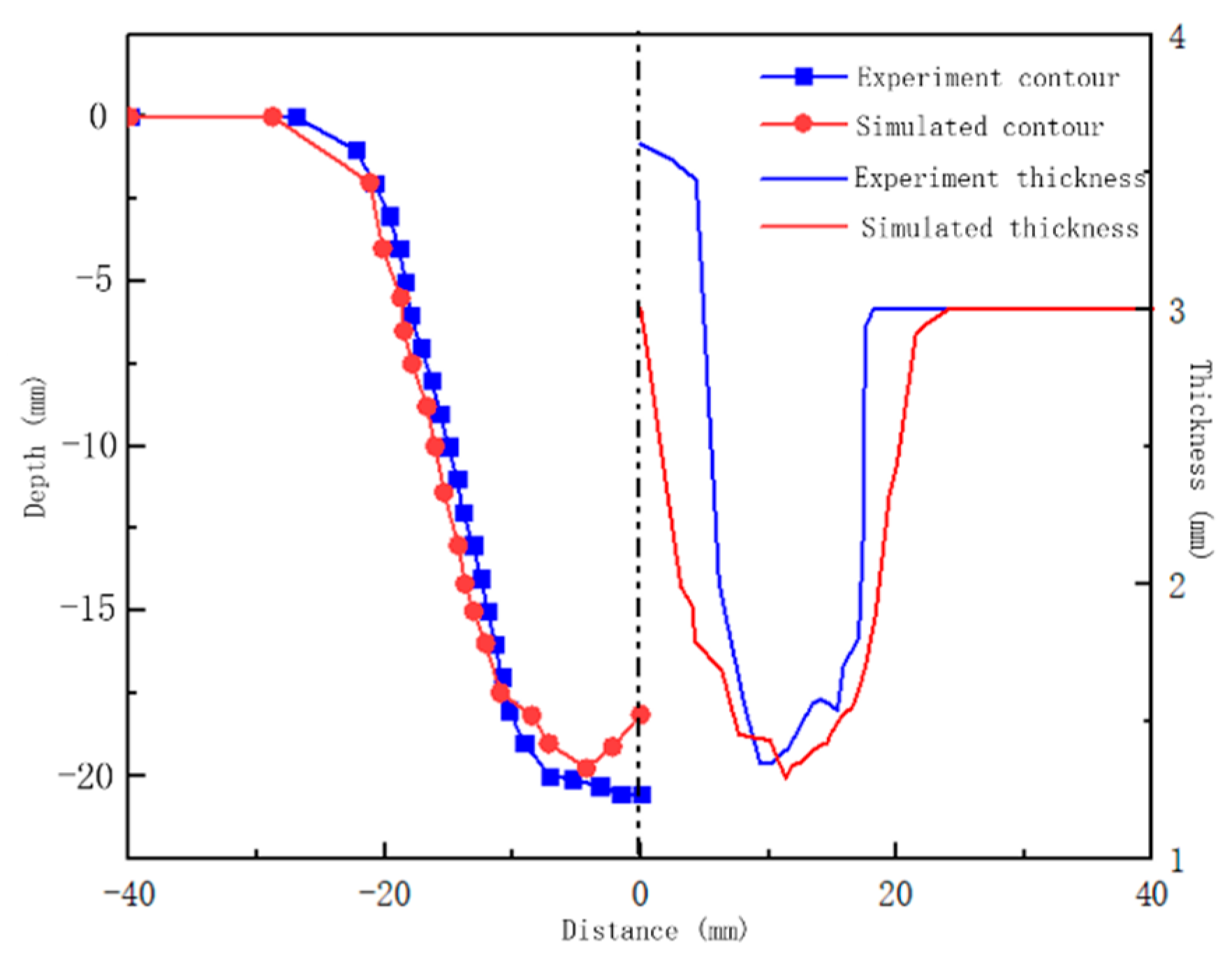
4.2. SPIF Experimental Validation

To order to understand the forming accuracy and surface quality of the truncated pyramids component under different forming angles, the optimal process parameters from the simulation were selected to conduct SPIF experiments with different forming angles (51 °, 54 ° and 57 °) at a forming temperature of 200 °C, a feed rate of 1000 mm/min and a forming tool rotation speed of 400 rpm. As shown in Figure 7, the morphology of the outer and inner surfaces of the truncated pyramid component at different forming angles is shown. It can be seen that the forming angle has a significant impact on the surface. The surface becomes smoother with the increasing forming angle. At the forming angle of 51°, obvious microcracks (indicated by the red dashed line) can be found at the corner of the outer surface. Microcracks are also found at the corner with a forming angle of 54°. With the increasing forming angle, not only the microcracks on the outer surface are improved, but also the wave ridges produced by the forming tool on the inner surface are gradually reduced [12]. Besides, more microcracks and wrinkles are observed on the outer surface compared to the inner surface. These localized microcracks and wrinkles on the outer surface lead to the cracking of the component upon further deformation. This is consistent with Hamilton [18] and Mohammad [29].
Measurement of the contour and wall thickness of the truncated pyramid component under different forming angles are shown in Figure 8. SPIF belongs to die-less forming, and the geometric contour does not fit with the design contour within a depth of 5 mm, showing a slight bending. However, it can be observed that the geometric contour of the region in the X direction has a smaller deviation compared to the design contour in the Y direction. The reason is that the billet formed in the X direction has a shorter side, and the relatively longer side has a shorter forming length to obtain effective support from the molds on both sides. The deeper the forming depth, the smaller the difference.
The larger the forming angle, the better the profile curve of the experimentally formed component fit well with the designed geometry. The longer edge of the sheet are less stable as the short edge during SPIF processing, this results in a higher thickness deviation in the Y direction compared to the X direction (Figure 8d). When the forming depth reaches around 20 mm, the contact area between the forming tool and the thin sheet increases significantly, and the heat generated causes the thin sheet to soften quickly. This not only results in the rapid wear of the thin sheet surface, but also causes bending in this area. This is also the reason why this area has the thinnest thickness. It is worth noting that the closer the center position is, the thicker the sheet becomes, even exceeding the initial thickness of the sheet. In the central area, the maximum thickness of the plate is 3.6 mm, 3.5 mm and 3.2 mm, respectively. This is because the formed component is in a pyramid shape, and as the depth gradually increases during the SPIF process, the area of the forming area of the forming tool gradually decreases. When reaching the bottom layer, the formed area is the smallest. Therefore, when the forming tool runs along the spiral trajectory, it causes the sheet to accumulate towards the middle under wear conditions. In summary, as the forming angle increases, the forming performance is better, and the surface quality and contour accuracy are better.
Combining simulation and modeling can provide a better understanding of the impact of forming angles on forming accuracy and surface quality. Figure 9 and Figure 10 illustrate the stress and equivalent strain distribution under different forming angles. It can be observed that the stress distribution on the wall of the three samples is uniform. From Figure 10, it can also be clearly seen that the equivalent strain value increases with the increase of the forming angle, and the distribution is more uniform. This indicates that the material has better fluidity and the deformation also becomes more uniform with the increase of the forming angle. However, significant stress concentration occurs at the corners of the truncated pyramid component.
As the forming depth increases, the formable area gradually decreases. In smaller forming areas, the forming tool will repeatedly squeeze the same area of the sheet, especially in the corner area, which can easily lead to local stress concentration. As shown in Figure 9, the maximum stress gradually decreases with the increase of forming angle, with the maximum stresses being 182 MPa, 179 MPa and 175 MPa, respectively. There is a significant stress concentration at the corner, which is also the reason for the formation of microcracks at the corner. In the center area at the bottom, we can also observe that the stress and strain gradually decrease as the forming angle increases (within the white box). This indicates that as the forming angle increases, the contact between the forming tool running along the spiral trajectory and the bottom center area gradually decreases.
In addition, the continuous rotation of the forming tool easily generates frictional heat during the forming process, and the heat generated by friction makes the forming tool prone to thermal cutting effects. At the same time, an increase in temperature will have a softening effect on the sheet material. Therefore, the increase in temperature and the lower strength of the sheet metal can easily lead to severe wear and even the generation of powder and debris during the forming process. This is also the reason why the thickness of the component decreases with the increase of forming depth (Figure 8d).

4.3. Performance and Microstructure

Based on the above study, we obtained the influence law of geometric accuracy of truncated pyramid component under different forming angles. For this purpose, further heat treatment processes were carried out to obtain mechanical properties for components. The truncated pyramids SPIFed at three different forming angles are T8 treated and then tested for their tensile properties (Table 2). At the forming angle of 51°, the tensile strength, yield strength and elongation were 542.1 MPa, 532.5 MPa and 5.4%, respectively. When the forming angle is 54°, the tensile strength increases to 551.3 MPa, the yield strength decreases to 523.5 MPa, and the elongation increases to 7.6%. When increasing the forming angle to 57°, the tensile strength, yield strength and elongation increased to 562.3 MPa, 533.6 MPa and 8.6%, respectively. It is found that the sample SPIFed at a forming angle of 57° has the best mechanical properties; it is compared to that made at low forming angle.
In order to understand the differences in mechanical properties between the above samples, observations and analyses from the microstructural point of view were carried out in this paper. EBSD and TEM observations were conducted on the wall area. As can be seen in Figure 11 below, during SPIF, the grains grows along the forming tool movement direction, and a large number of low angle grain boundaries can be observed inside the grains (grain boundaries of 2–15° are marked white; grain boundaries greater than 15° are marked black).
When the forming angle is 51°, obvious coarse grains (grain size approximately 180 μm, as shown by the black dashed line in Figure 9a are found). There were not many low angle grain boundaries observed inside the grains, indicating that dynamic recrystallization occurred during the forming process, with some grains experiencing abnormal growth. The uneven grain size indicates that the deformation is not uniform when the forming angle is 51°. Moreover, it is found that the grains are refined with increasing forming angle. It can be considered that at the forming angle of 51°, it is at the critical degree of deformation, after which the recrystallized grains become finer with increasing deformation. When the forming angle is 54°, obvious coarse fibrous grains can be observed. There are fine recrystallized grains forming a chain like structure at the grain boundaries of fibrous grains (as shown by the black dashed line in Figure 11b). The grain orientation of recrystallized grains is not the same as that of the fibrous grains, because discontinuous dynamic recrystallization occurs during the forming process [27,28]. Dislocations tend to accumulate at grain boundaries and rearrange to form small angle grain boundaries. With the increase of strain induced dislocations, small angle grain boundaries transform into large angle grain boundaries, forming recrystallized grains. When the formation angle is increased to 57°, the size of the grain decreases and there are a large number of fine equiaxed recrystallized grains formed, with an average grain size of 8.3 μm, indicating a good grain refinement effect. Earlier studies [24] have shown that the surface quality worsens under large grain size. which is consistent to our observations. The improved surface quality of the 57° SPIFed sample is related with finer grains (Figure 11c) of the material. The reason for this is that the local deformation is more uniform for SPIF process at higher forming angle, which leads to a smaller distortional energy difference across the grain boundaries and thus suppresses grain growth, improving the surface quality during forming. It has been shown [25] that equiaxial fine grains substantially increase the strength and the plasticity of the alloy. This explains the better performance of the sample SPIFed at higher angle (57°). However, lower forming angles generate larger grains during the forming process, which not only have adverse effects on surface quality but also reduce strength and elongation.
In addition, precipitation strengthening is an important factor in improving the high strength of Al-Li alloys, and the T1 phases is the most important strengthening precipitation phase in Al-Li alloys. The precipitation phase is the most important factor in precipitation strength. TEM observations were performed on the samples SPIFed at different angles along [110] zone axis, as shown in Figure 12. It can be found by SAED and TEM that the precipitated phase is T1 phases and the presence of θ phase is not observed. The quantity density of T1 phases in aging state with different forming angles was statistically analyzed. The quantity density and distribution of T1 phases precipitated in the forming angle 57° (267.3 μ m 2 ) is higher and more uniform than those at 51° (177.5 μ m 2 ) and 54° (233.1 μ m 2 ), which also contribute to its higher strength. It is widely reported in the literature that higher T1 phases density is beneficial for strength improvement [24,25,26,27,28].

5. Conclusions

In this work, The compatibility of SPIF processing with Al-Li alloy was studied. The influence of forming angle on the geometry accuracy and strength of truncated pyramid component was investigated through numerical simulation and experimental tests. The results show that as the forming angle increases, the maximum thinning rate and wall thickness deviation gradually decrease. The geometric accuracy of the component formed at the higher angle of 57° is the best among others. The SPIF experiment shows that with increasing forming angle, the surface quality, geometry accuracy and wall thickness uniformity of the formed truncated pyramid component have been effectively improved. The reason is explained by the stress and strain modelling and microstructural observations. At higher forming angles, the stress is lower and the strain distribution is more uniform. In addition, grain refinement and a finely dispersed precipitates are achieved in the sample SPIFed at higher angles, which effectively improves the strength and plasticity of the material.

Author Contributions

Z.T. investigation, methodology and writing—original draft; W.X.: resources, conceptualization and writing—review and editing; Y.Z.: visualization, supervision and data-curation; J.Z.: formal analysis, funding acquisition and data curation. All authors have read and agreed to the published version of the manuscript.

Funding

This work was supported by the National Natural Science Foundation of China (Grant No. U21B6004), Major Project of Scientific Innovation of Hunan Province (Grant No. 2021GK1040).

Institutional Review Board Statement

Not applicable.

Informed Consent Statement

Not applicable.

Data Availability Statement

Data available on request due to restrictions e.g., privacy or ethical. The data presented in this study are available on request from the corresponding author.

Conflicts of Interest

The authors declare that they have no known competing financial interests or personal relationships that could have appeared to influence the work reported in this paper.

References

  1. Martins, P.A.F.; Bay, N.; Skjoedt, S.M.B. Theory of single point incremental forming. CIRP Ann. 2008, 57, 247–252. [Google Scholar] [CrossRef]
  2. Skjoedt, M.; Bay, N.; Endelt, B.; Ingarao, G. Multi stage strategies for single point incremental forming of a cup. Int. J. Mater. Form. 2008, 1, 1199–1202. [Google Scholar] [CrossRef]
  3. Said, L.B.; Bouhamed, A.; Wail, M.; Ayadi, B.; Betrouni, S.; Hajji, H.; Dammak, F. SPIF manufacture of a dome part made of AA1060-H14 aluminum alloy using CNC lathe machine: Numerical and experimental investigations. ARAB J. Sci. Eng. 2021, 46, 12207–12220. [Google Scholar] [CrossRef]
  4. Bouhamed, A.; Mars, J.; Jrad, H.; Ben Said, L.; Wali, M.; Dammak, F.; Torchani, A. Identification of fully coupled non-associated-ductile damage constitutive equations for thin sheet metal applications: Numerical feasibility and experimental validation. Thin Wall Struct. 2022, 176, 109365. [Google Scholar] [CrossRef]
  5. Ben Said, L. The incremental sheet forming; technology, modeling and formability: A brief review. Proc. Inst. Mech. Eng. Part E J. Process. Mech. Eng. 2022, 236, 6. [Google Scholar] [CrossRef]
  6. Khan, S.; Hussain, G.; Ilyas, M.; Rashid, H.; Khan, M.I.; Khan, W.A. Appropriate heat treatment and incremental forming route to produce age-hardened components of Al-2219 alloy with minimized form error and high formability. J. Mater. Process. Tech. 2018, 256, 262–273. [Google Scholar] [CrossRef]
  7. Dursun, T.; Soutis, C. Recent developments in advanced aircraft aluminium alloys. Mater. Des. 2014, 56, 862–871. [Google Scholar] [CrossRef]
  8. Chaturvedi, M.C.; Chen, D.L. Effect of specimen orientation and welding on the fracture and fatigue properties of 2195 Al-Li alloy. Mater. Sci. Eng. A 2014, 387–389, 465–469. [Google Scholar] [CrossRef]
  9. Qin, H.; Zhang, H.; Wu, H. The evolution of precipitation and microstructure in friction stir welded 2195-T8 Al-Li alloy. Mater. Sci. Eng. 2015, 626, 322–329. [Google Scholar] [CrossRef]
  10. Hales, S.J.; Hafley, R.A. Texture and anisotropy in Al-Li alloy 2195 plate and near-net-shape extrusions. Mater. Sci. Eng. A 1998, 257, 153–164. [Google Scholar] [CrossRef]
  11. Kalu, P.N.; Zhang, L. Texture evolution in Al-Li 2195 alloy during net shape roll forging. Scr. Mater. 1998, 39, 175–180. [Google Scholar] [CrossRef]
  12. Hang, E.; Jeswiet, J. Analysis of surface roughness for parts formed by computer numerical controlled incremental forming. J. Eng. Manuf. 2004, 218, 1307–1312. [Google Scholar]
  13. Li, J.-F.; Liu, D.-Y.; Ning, H.; Liu, C.; Ma, P.-C.; Chen, Y.-L.; Zhang, X.-H. Experimental quantification of “hardenability” of 2195 and 2050 Al-Li alloys by using cold-rolled sheets. Mater. Charact. 2018, 137, 180–188. [Google Scholar] [CrossRef]
  14. Shi, X.; Gao, L.; Khalatbari, H.; Xu, Y.; Wang, H.; Jin, L. Electric hot incremental forming of low carbon steel sheet: Accuracy improvement. Int. J. Adv. Manuf. Technol. 2013, 68, 241–247. [Google Scholar] [CrossRef]
  15. Liu, Z.; Liu, S.; Li, Y.; Meehan, P.A. Modeling and optimization of surface roughness in incremental sheet forming using a multi-objective function. Mater. Manuf. Process. 2014, 29, 808–818. [Google Scholar] [CrossRef]
  16. Petek, A.; Kuzman, K.; Kopac, J. Deformation and forces analysis of single point increment sheet metal forming. Arch. Mater. Sci. Eng. 2009, 35, 107–116. [Google Scholar]
  17. Jawale, K.; Duarte, J.F.; Reis, A.; Silva, M.B. Microstructural investigation and lubrication study for single point incremental forming of copper. Int. J. Solids Struct. 2018, 151, 145–151. [Google Scholar] [CrossRef]
  18. Hamilton, K.; Jeswiet, J. Single point incremental forming at high feed rates and rotational speeds: Surface and structural consequences. CIRP Ann. Manuf. Technol. 2010, 59, 311–314. [Google Scholar] [CrossRef]
  19. Torsakul, S.; Kuptasthien, N. Effects of three parameters on forming force of the single point incremental forming process. J. Mech. Sci. Technol. 2019, 33, 2817–2823. [Google Scholar] [CrossRef]
  20. Mostafanezhad, H.; Menghari, H.G.; Esmaeili, S.; Shirkharkolaee, E.M. Optimization of two-point increment forming process of AA1050 through response surface methodology. Measurement 2018, 127, 21–28. [Google Scholar] [CrossRef]
  21. Hussain, G.; Lin, G.; Harat, N. A new parameter and its effect on the formability in single point incremental forming: A fundamental investigation. J. Mech. Sci. Technol. 2010, 24, 1617–1621. [Google Scholar] [CrossRef]
  22. Mohammadi, A.; Vanhove, H.; van Basel, A.; Duflou, J.R. Enhanced formability of age-hardenable aluminium alloys by incremental forming of solution-treated blanks. Key Eng. Mater. 2013, 549, 164–171. [Google Scholar] [CrossRef]
  23. Kumar, A.; Gulati, V.; Kumar, P.; Singh, V.; Kumar, B.; Singh, H. Parametric effects on formability of AA2024-O aluminum alloy sheet in single point incremental forming. J. Mater. Res. Technol. 2019, 8, 1461–1469. [Google Scholar] [CrossRef]
  24. Raabe, D.; Sachtleber, M.; Weiland, H.; Scheele, G.; Zhao, Z. Grain-scale micromechanics of polycrystal surfaces during plastic straining. Acta Mater. 2003, 51, 1539–1560. [Google Scholar] [CrossRef]
  25. Furukawa, M.; Horita, Z.; Nemoto, M.; Valiev, R.; Langdon, T. Microhardness Measurements and the Hall-Petch Relationship in an Al-Mg Alloy with Submicrometer Grain Size. Acta Mater. 1996, 44, 4619–4629. [Google Scholar] [CrossRef]
  26. Nayan, N.; Murty, S.N.; Chhangani, S.; Prakash, A.; Prasad, M.J.N.V.; Samajdar, I. Effect of temperature and strain rate on hot deformation behavior and microstructure of Al-Cu-Li alloy. J. Alloys Compd. 2017, 723, 548–558. [Google Scholar] [CrossRef]
  27. Shen, B.; Deng, L.; Wang, X. A new dynamic recrystallisation model of an extruded Al-Cu-Li alloy during high-temperature deformation. Mater. Sci. Eng. A 2015, 625, 288–295. [Google Scholar] [CrossRef]
  28. Zhang, J.; Yi, Y.; Huang, S.; Mao, X.; He, H.; Tang, J.; Guo, W.; Dong, F. Dynamic recrystallization mechanisms of 2195 aluminum alloy during medium/high temperature compression deformation. Mater. Sci. Eng. A 2021, 804, 140650. [Google Scholar] [CrossRef]
  29. Mohammad, J.M.; Mostafa, V.; Mohsen, S. Ductile damage and deformation mechanics in multistage single point incremental forming. Inter. J. Mech. Sci. 2018, 136, 396–412. [Google Scholar]
Figure 1. Heat treatment process diagram.
Applsci 13 06144 g001
Figure 2. (a) Truncated pyramid component mold; (b) 3D model of the component, the dashed lines represent the geometric profile measurement area; (c) the dimensions of the sheet (160 × 80 mm) and forming area (130 × 50 mm).
Applsci 13 06144 g002
Figure 3. Stress-strain curves at different temperatures.
Applsci 13 06144 g003
Figure 4. (a) Single point incremental forming components; (b) simulation results.
Applsci 13 06144 g004
Figure 5. Comparison of contour and thickness in the experimental results and simulation results of single point incremental forming.
Applsci 13 06144 g005
Figure 6. Maximum thinning rate and standard deviation of wall thickness of truncated pyramids component under different forming angles.
Applsci 13 06144 g006
Figure 7. Surface morphology of truncated pyramids component under different forming angles. (a,b) 51°, (c,d) 54° and (e,f) 57°.
Applsci 13 06144 g007
Figure 8. Geometry profile and wall thickness distribution of the component under different forming angles: (a) 51°, (b) 54° and (c) 57°; (d) thickness distribution.
Applsci 13 06144 g008
Figure 9. Stress distribution under different forming angles at a forming temperature of 200 °C: (a) 51°, (b) 54° and (c) 57°.
Applsci 13 06144 g009
Figure 10. Strain distribution under different forming angles at a forming temperature of 200 °C: (a) 51°, (b) 54° and (c) 57°.
Applsci 13 06144 g010
Figure 11. EBSD grain distribution at different forming angles: (a) 51° (b) 54 and (c) 57°.
Applsci 13 06144 g011
Figure 12. TEM images at different forming angles: (a) 51°, (b) 54° and (c) 57°.
Applsci 13 06144 g012
Table 1. Material parameters of Al-Li alloy at 200 °C.
ρ /t.mm−3 σ m /MPa σ s /MPa E/MPa ν
2.59 × 10−9188.3124.163,0000.33
Table 2. Tensile properties of SPIF angles of 51°, 54° and 57° after T8 aging.
Forming AngleTensile Strength/MPaYield Strength/MPaElongation
51°542.1532.55.4
54°551.3523.57.6
57°562.3533.68.6
Disclaimer/Publisher’s Note: The statements, opinions and data contained in all publications are solely those of the individual author(s) and contributor(s) and not of MDPI and/or the editor(s). MDPI and/or the editor(s) disclaim responsibility for any injury to people or property resulting from any ideas, methods, instructions or products referred to in the content.

