Article

Geometric Error Parameterization of a CMM via Calibrated Hole Plate Archived Utilizing DCC Formatting

Precision Mechanical Metrology Research Laboratory, Center for Measurement Standards, Industrial Technology Research Institute, 321, Sec. 2, Kuang Fu Rd., Hsinchu 30011, Taiwan
*
Author to whom correspondence should be addressed.
Appl. Sci. 2023, 13(10), 6344; https://doi.org/10.3390/app13106344
Submission received: 15 April 2023 / Revised: 18 May 2023 / Accepted: 18 May 2023 / Published: 22 May 2023

Abstract

:
This study implemented the measurement results and administrative information obtained from the hole plate into the Digital Calibration Certificate (DCC). The DCC comprises three parts: Norms and Standards, Hierarchical Structure, and XML as Exchange Format. DCCs play a significant role in the field of metrology and statistics by ensuring data interoperability, correctness, and traceability during the conversion and transmission process. The hole plate is a length standard used for two-dimensional geometric error measurements. We evaluated the accuracy of the high-precision coordinate measuring machine (CMM) in measuring a hole plate and compared the measurement error results obtained from the hole plate with those of the laser interferometer, autocollimator, and angle square. The results show that the maximum difference in linear error is −0.30 μm, the maximum difference in angle error is −0.78″, and the maximum difference in squareness error is 4.54″. The XML is designed for machine-readability and is modeled and edited using the XMLSpy 2022 software, which is based on information published by PTB. The administrative management and measurement results tasks are presented in PDF format, which is designed for human-readability and ease of use. Overall, we implemented the measurement results and information obtained from the hole plate into the DCC.

1. Introduction

The quality of industrial products depends on the production machinery, raw materials, and equipment. Properly measuring the dimensions of products is the foundation of manufacturing, and the basic components of the manufacturing process should be designed to meet the desired product specifications [1]. All processes, from the material quality and processing to assembly and quality inspection, are measured and inspected using the same standards to ensure that the products meet the design specifications and quality requirements [2]. Therefore, measuring equipment and instruments play an important role in the industrialization process. If any measurement or inspection is not done properly, the quality cannot be guaranteed [3,4]. Regular calibration and intermediate checks can detect problems early and ensure the accuracy of measuring equipment. Calibration certificates are important in the field of metrology because they help ensure accurate measurements in manufacturing. These certificates provide information on measurement uncertainty and calibration traceability to users. In the traditional system of calibration certificate management, data collected during the experiment process are error-prone, time-consuming, and difficult to manage because the collected data are based on manual systems [5]. Therefore, modernizing the calibration certificate management process is necessary to improve efficiency and accuracy.
In recent years, the rapid advancement of digitalization has brought significant changes to society. The COVID-19 pandemic, also known as the coronavirus pandemic, has further accelerated the digital transformation of human life [6,7,8]. Therefore, establishing a reliable data foundation is critical for the development of science and technology in the digital era. Reliable data are obtained from accurate measurement standards, and the digital calibration certificate (DCC) is a tool that can be used for the authenticated transmission, verification, and electronic storage of calibration results [9]. The concept of the DCC structure is being developed by the Physikalisch-Technische Bundesanstalt (PTB), a German federal institute for physics and technology, and can be applied to all facilities that require metrological traceability of their measurements. To meet the industry’s demands for large amounts of data, real-time response, and digital models, the PTB and the US National Institute of Standards and Technology (NIST) have proposed plans for the development and implementation of measurement standards [10]. This demonstrates the need for improvement and modernization of measurement standards to keep pace with the digital transformation.
With the goal of advancing digital transformation, PTB has identified four primary areas: metrology services, dimensional data analysis, communication systems, and virtual measuring devices [11]. The concept of a metrology cloud involves various stages, including a reliable metrology core platform, reference architectures, technology-driven metrological support services, and data-driven metrological support services [12]. NIST has developed the Quality Information Framework (QIF) in the field of metrology by combining aspects of manufacturing, software, hardware, and equipment [13]. QIF, which is based on XML technology, is feature-based manufacturing data designed to ensure the traceability of all data. The areas where QIF is applied include Model Based Definition (MBD), Plans, Resources, Rules, Dimensional Measuring Interface Standard (DMIS), Results, and Statistics [14]. Based on research by the National Physical Laboratory (NPL) and PTB, electronic files will soon replace paper reports for calibration certificates. The electronic certificate, known as the DCC, can be electronically delivered to anyone who has a need for the certificate. This standard is crucial for testing laboratories since it is an international guideline that encompasses method validation, traceability, and measurement uncertainty [15]. The research focuses on minimum requirements for DCCs with clearly defined needs from laboratories and customers, following ISO 17025 [16,17]. The DCC report will be presented in XML and includes information about the data, such as the uncertainty based on ISO GUM and the International System of Units. Metric conversion can be performed to meet the client’s needs from a test laboratory or calibration laboratory. To avoid errors caused by human factors, software must automatically translate the data. Additionally, digital security measures have been enhanced to ensure the secure delivery of the DCC to the client, such as identity verification and software security. The use of XML enables machines to easily read the DCC, making it popular for Industry 4.0 and future digital metrology work [18,19]. In conclusion, the DCC, an electronic certificate developed by PTB and NPL, meets the traceability and uncertainty requirements of the ISO 17025 standard and ensures secure delivery of the DCC to the client, and will soon replace paper calibration certificates (PCC) [20,21,22].
The digital transformation of the manufacturing industry has revolutionized processes, enhancing consistency, security, and efficiency through digital technology. By gathering and analyzing data automatically during production, digital technology facilitates data exchange, integration, and remote management and monitoring [16]. Industry 4.0, also known as the fourth industrial revolution, combines technologies such as IoT, AI, and extensive data analysis, using the Cyber–Physical System (CPS) concept to bring manufacturing and measurement processes into the digital realm [23,24]. The PTB is focused on managing measurement technology to ensure calibration and traceability compliance [25]. To address this, PTB proposes using a standardized digital data exchange format, with XML as the common format, to publish a DCC based on SI units format. PTB has defined an XML data exchange framework, which ensures the interoperability and traceability of data in the conversion and transmission process. This approach will help address potential problems in the digital transformation of the manufacturing industry, ensuring compliance with calibration and traceability standards [10,16,23,26,27,28]. Currently, users are required to manually input detected errors into compensation tables on various controllers. This manual process can potentially result in accidents, such as collisions involving knives or machine tools, due to abnormal compensation operations or programming errors. However, the utilization of XML files can facilitate the development and implementation of geometric error compensation for machine tool controllers, thereby enhancing the measurement precision of both machine tools and CMMs. It is crucial to emphasize that the values present in the DCC do not indicate the current parameters in the compensation tables. Residual errors or geometric errors represent the disparities between measured values and expected values, reflecting the remaining errors in the system after compensation. Geometric errors are particularly influential in the measurement accuracy of a five- or three-axis machine. International standard specification (ISO) 230-1 [29] and ISO 230-7 [30] identify 43 geometric errors in a five-axis machine, consisting of 21 errors of three linear axes and 22 errors of two rotary axes. For example, the hole plate [31,32,33,34,35] made of NEXCERA material from Krosaki in Japan is used to measure the CMMs with 21 geometric errors of three linear axes. Miura et al. [35] utilized a hole plate to measure the CMM and developed a Monte Carlo simulation method for estimating uncertainty through computer simulation. By measuring and compensating for geometric errors, the CMMs and machine tools can be improved. Kim et al. [36] proposed a new method for objectively evaluating the accuracy of digitized full dental arch models using a CMM and compared the accuracy of four different digitization methods, including true model intraoral scans, impression CBCT scans, cast CBCT scans, and cast extraoral scans, by performing 12 automatic linear measurements on the models. Kritikos et al. [37] presented a study on the uncertainty analysis of measurements performed by a ZEISS CenterMax CMM, focusing on the variables of parallelism, angularity, roundness, diameter, and distance. The study found that the interaction effects among stylus diameter, step width, and speed were active at a 95% confidence level. These studies highlight the importance of measurement accuracy and precision in the digitalization of industries.
In this study, we present a method for generating DCC using a reference standard hole plate to measure CMM. We begin by examining the related research papers on PTB and NIST in the Introduction Section, which focus on the formulation and implementation plans for measurement standards and the advantages of DCC for the development of the measurement field in response to the digital transformation. Section 2 provides relevant background information on DCC, including the Norms and Standards, Hierarchical Structure, and XML as Exchange Format. In addition, we present an example of administrative information in the XML. Section 3 describes the experiment of measuring CMM using the hole plate. The results are compared with traditional standards such as laser interferometer, autocollimator, and angle square. To make the measurement results readable by both humans and machines, we convert them into XML and PDF formats using XMLSpy software, respectively. This approach combines software and hardware devices in the manufacturing industry. Finally, in Section 4, we provide a conclusion to our work.

2. Background and Example

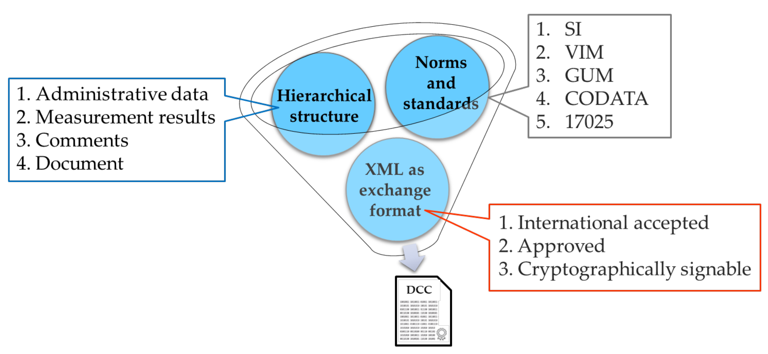
2.1. Digital Calibration Certificates

As shown in Figure 1, a DCC comprises three parts: Norms and Standards, Hierarchical Structure, and XML as Exchange Format. The Norms and Standards must comply with international standards such as The International System of Units (SI), International Vocabulary of Metrology (VIM), Guide to the Expression of Uncertainty in Measurement (GUM), Committee on Data for Science and Technology (CODATA), and ISO 17025. Since 1960, the SI system has been the preferred system of units globally. It comprises seven base units and 22 derived units, all of which are based on natural constants. The definitions of these units are established using a set of seven defining constants, which are the fundamental feature of the entire system. VIM is a standardized set of definitions and terms used in metrology that is developed at an international level by various standardization bodies, metrology organizations, and accreditation laboratories. Its aim is to provide a clear and unique language for anyone interested in measurements. GUM provides guidelines for evaluating and expressing uncertainty in measurement that can be used for a wide range of measurements. When an instrument is calibrated, it must be traceable back to a common standard, and this requires estimating and showing the uncertainty at each step of the traceability chain. CODATA periodically issues a set of recommended values for fundamental physical constants. These values are established by analyzing all the available theoretical and experimental data using a least-squares adjustment method. The CODATA task group on fundamental constants plays a crucial role in selecting and evaluating the data to ensure accuracy. ISO 17025 is a well-recognized quality standard that outlines the necessary requirements for calibration and testing labs to demonstrate their competence, technical proficiency, and ability to produce valid results.
The Hierarchical Structure has four sections: administrative data, measurement results, comments, and a document. The administrative data are required and regulated, and include fundamental information such as the name of the measurement object, calibration laboratory, reference number, and date. The measurement results are also required but partially restricted, and any legal data must be expressed in the SI units. For example, the type definition of the two tree structure elements designated as administrative Data and measurement Results is shown in Figure 2 [28,38,39]. The administrative Data element has six mandatory child elements and two optional child elements, and the measurement Result element has six optional child elements and two mandatory child elements. The comments section is optional and unregulated, allowing the calibration laboratory to add any additional digital information they deem necessary. For instance, the human-readable document is optional but recommended, and users can be provided with a digital copy of the analogue calibration certificate for easy accessibility. In other words, the administrative data and measurement results elements are necessary components of a valid DCC. Without these elements, a DCC cannot be considered complete. On the other hand, the comments and document elements are not required and can be included at the discretion of the user.
The XML as Exchange Format is an internationally accepted, approved, and cryptographically signable XML exchange file that is used as a data format, facilitating efficient and accurate calibration information management. In addition, the use of cryptographic protection ensures the integrity and authenticity of the data, which is essential for building trust and ensuring that the data have not been tampered with. The IEC TS 62720 standard [40] provides guidance on handling SI units and derived units in XML to ensure compliance with international standards and facilitate interoperability between different organizations [9]. XML is advantageous as a data exchange format for DCCs because it is both machine-readable and human-readable, allowing for easy processing by computers and understanding by humans [26]. DCCs are electronic documents that use XML as their data exchange format and are validated against schema definitions. The use of XML allows for the consistent and predictable formatting and structuring of data, which is essential for information exchange between different systems, and the use of XML schema definitions (XSDs) ensures that the data are structured and formatted in a consistent and predictable way. The use of XML as the data exchange format for DCCs is a vital component of the digital transformation of the manufacturing industry, as it enables easy and efficient information exchange, ensures compliance with international standards, and provides secure and long-term storage of data. They are also more accurate, using authenticated, encrypted, and signed transmissions to ensure the reliability of calibration results.

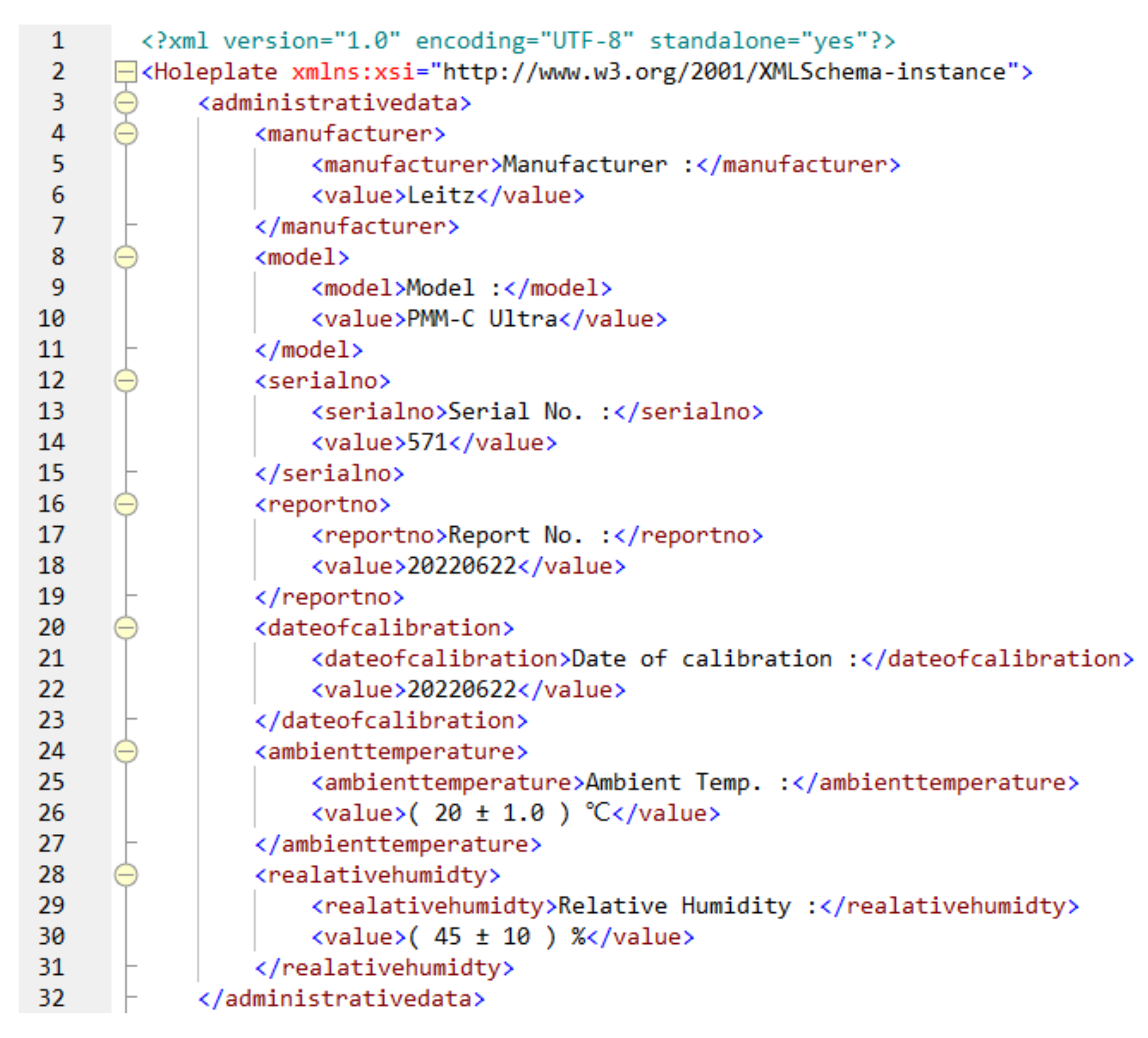
2.2. The Example of Administrative Information in the XML

To facilitate the use of calibration certificates, electronic calibration certificates are increasingly being introduced into practice. The DCC provides a standardized structure for calibration certificates, which can be easily read and interpreted by both humans and machines. The DCC can be used in various settings, including industrial manufacturing, testing and calibration laboratories, and scientific research. Many calibration laboratories use Microsoft Excel for data acquisition, result calculation, and report generation. However, programming skills are required to generate a validated DCC. As shown in Figure 3, the XML is designed for machine-readable administrative information and can be created and edited using XMLSpy software based on the PTB’s published information. To create an element, the user needs to use a start tag and an end tag. The root element is a mandatory component for every valid DCC file, and all other elements are either direct or indirect children of this root element. There can be multiple child elements under a given element, and those elements that do not have any child elements are referred to as “data” elements [28]. For example, <model> represents the start tag, and </model> represents the end tag, which contains a forward slash after the opening angle bracket. The entire content of the element must be enclosed between these tags. In XML, <model> and </model> represent the information related to the model content, while Model: is the actual XML content within the XML content. Additionally, PMM-C Ultra is a value container that can store information such as a quantity value, unit, comment, and more within an element. The administrative information included in the XML pertains to the high-precision CMM used in the study. The CMM was manufactured by Leitz, with a model of PMM-C Ultra and a serial number of 571. To ensure consistency during the measurement process, the temperature of the environment was kept at 20 ± 1 °C, and the relative humidity was maintained at 45 ± 10%.

3. Experiments

The measurement process involved placing the hole plate at the center of the machine coordinate system and measuring it in three different directions on the machine bed. The hole plate, shown in Figure 4, is a length standard used for two-dimensional geometric measurements. It has a total of 44 holes with a nominal diameter of 20 mm, spaced at a nominal distance of 50 mm between each other. The plate has dimensions of 550 mm × 550 mm and is made of NEXCERA, a material with a low thermal expansion coefficient of 0.03 × 10⁻⁶/°C. Geometric errors in CMMs can result from imperfections in the faulty assembly in the system, leading to inaccurate measurements and affecting overall accuracy. To mitigate this issue, using a standard such as the hole plate enables more precise measurements and improved accuracy in analyzing geometric errors. The hole plate is a two-dimensional standard used to measure orthogonal directions or planar measurements. As the plate is rotated, the X and Y coordinates are changed in the CMM coordinate frame. By using this standard as a traceability reference, the features of the workpiece can be accurately measured, and their positions’ coordinates can be obtained.
For the measurement process, the CMM software automatically generated measurement paths for all the holes, and the inner diameter was calculated using a four-point circle [35,41,42]. Figure 5 displays the hole plate measurement in different directions. For each direction, the stylus calibration was performed as the probe direction was different. Furthermore, the axis alignment between the hole plate and the bed was adjusted, the touch-trigger probe was calibrated, and forward and reverse measurements were conducted, as required by ISO 230-2 [43]. ISO 230 comprises a broad spectrum of assessments that can be utilized to assess the comprehensive accuracy and functionality of machine tools. For example, Lee et al. [44] employed specialized equipment such as LaserTRACER to gauge the geometric errors of CMMs. The positioning accuracy and repeatability of linear axes in machine tools are determined using ISO 230-2 and ISO 230-6 [45]. To measure the three-dimensional coordinate position, the hole plate was set up in three different directions. According to ISO 230-1, three-axis machine tools utilize a right-handed Cartesian coordinate system with three linear axes: the X-axis, Y-axis, and Z-axis. There are six errors in a linear axis, including a position error, two straightness errors, three angular errors, and there is a squareness error between axes. The coordinate system made up of the three linear axes encompasses a total of 21 errors. As displayed in Table 1, the table presents the 21 geometric errors of three linear axes and shows all geometric errors of three-axis CMM.
In order to achieve accurate results, the axis alignment between the hole plate and the bed was adjusted before the measurement. In the previous article by Trapet and Wäldele, they described the evaluation of 21 geometric errors using CMM to measure the hole plate, which we will only briefly discuss here. To evaluate position errors, measurements are taken from both sides of the plate at the same orientation or in the upper and lower positions, and then averaged to eliminate the effects of rotational errors. For squareness errors, data sets are prepared in the same way as for the position error analysis. The nominal u values of the calibrated plate are subtracted from the measurement data set and a regression line is calculated. Similarly, the nominal v value is subtracted from the same set and a regression line is calculated. The average squareness error between the two respective CMM axes is then obtained by summing the negative pitch angles of both regression lines. To analyze the 21 items of geometric error of the CMM, the relationship between the CMM coordinate axes, the hole plate, and a homogeneous transformation matrix (HTM) was used. The equation T x w = T s w T z s T y z T x y ,   T x w represents the HTM used to represent the relationship between adjacent coordinate axes. T s w represents the homogeneous coordinate transformation matrix of the hole plate coordinate position relative to the column, which has three squareness errors. T z s represents the homogeneous coordinate transformation of the column relative to the Z-axis, which has six geometric errors of the Z-axis. T y z represents the homogeneous coordinate transformation matrix of the Z-axis moving system relative to the Y-axis, which has six geometric errors of the Y-axis. T x y represents the homogeneous coordinate transformation matrix of the Z-axis moving system relative to the X-axis, including six geometric errors of the X-axis. To determine the geometrical error of the measuring machine at each coordinate point, the center coordinate position of each hole in the hole plate was measured. The difference between the coordinate position of the ideal hole and the actual hole was calculated, and the resulting difference value was used to determine the geometrical error. The HTM was utilized to investigate squareness error, positioning error, straightness error, and angle error. The measurement range of each error was between 0 mm and 550 mm, with a total of 12 points and a measurement interval of 50 mm. These errors can arise from a variety of factors, such as flawed assembly and geometry imperfections. Regular calibration of machine tools is necessary to maintain their accuracy and detect and rectify any geometric errors that may exist. By identifying and correcting the 21 geometric errors that can occur in these CMMs, manufacturers can ensure that their machine tools are operating at their maximum accuracy and producing high-quality products.
To confirm the measurement accuracy of the hole plate, the results were compared with traditional standards. The measurements of the hole plate require a total of 2.5 h. When compared to traditional measurement methods such as the laser interferometer, autocollimator, and angle square, the laser interferometer takes 50 min, the autocollimator takes 50 min, and the angle square takes 20 min. Therefore, the traditional measurement methods require a total of 2 h to complete. The measurement procedure is followed by ISO 10360-2 [46]. Figure 6 shows the schematic representation of the experimental setup involving a laser interferometer, an autocollimator, and an angle square. The laser interferometer and autocollimator have to place three positions to measure X-axis, Y-axis, and Z-axis, respectively. The angle square actually requires three rotated measurements for XY-plane, YZ-plane, and XZ-plane. These three measuring instruments were employed to compare the measurement outcomes with the hole plate. We have incorporated a comparison of geometric errors between our experimental results in Figure 7 of the revised manuscript. As shown in Figure 7, the largest positioning error for Eyy is −0.30 μm, while the largest angular error for Ebx is −0.78″. Moreover, we measured the squareness error using both a hole plate and an angle square, resulting in deviations of 89.99843° and 89.99717°, respectively. The difference in squareness error deviations for the Ecox after conversion is 4.54″. The results showed that the measurement accuracy of the hole plate was high and comparable to traditional standards, with a maximum difference of −0.30 μm for linear error, −0.78″ for angle error and 4.54″ for squareness error. Using the above described HTM, the maximum volumetric error was 2.70 μm. As shown in Figure 8, the figure presents the DCC structure for the hole plate measurement results of a CMM. The geometric position error of the measurement results was converted into XML for machine readability. The measurement results of the geometric error of the three linear axes of the CMM were obtained by measuring a hole plate. The results indicate that there are six geometric errors for every axis, with one error value for every 50 mm. The word Model presented in Figure 9 can correspond to the word <model>Model:</model> of the XML in Figure 8, and PMM-C Ultra can also correspond to the XML code of <value>PMM-C Ultra</value>. The figure illustrates the measurement results of the geometric errors for a range of distances from 0 mm to 550 mm, with measurements taken at 50 mm intervals, resulting in a total of 12 errors for each geometric parameter. In addition, there are three geometric error values for squareness. Overall, the measurement data were exported in PDF format for easy reading and use by users. These findings highlight the importance of regularly calibrating CMMs to ensure their accuracy and the production of high-quality products.
The uncertainty evaluation of the hole plate measurement method is based on the ISO Guide to the Expression of Uncertainty in Measurement (GUM) [47]. Table 1 shows the uncertainty budget for the measured hole plate method. Some influence quantities are directly measured and estimated, called Type A. Other influence quantities use specification knowledge to estimate using a set of probability distributions, called Type B. The measurement equation is as follows:
d = l l s ( 1 α Δ T )
where d is deviation value, l is the measured length of the CMM under measurement at 20 °C, α is thermal expansion coefficient of the CMM under measurement, ΔT is the temperature difference between the temperature of the CMM under measurement at 20 °C, and ls is the standard length of the hole plate at 20 °C.
The measurement uncertainty of the hole plate method originates from four influence sources to contribute to the measured value ε, including the length of the CMM l, the standard length of the hole plate ls, the thermal expansion coefficient α and the temperature difference ΔT. The measured length contains repeatability of CMM measurement, resolution of the CMM, and setup errors of the hole plate.
ε = f ( l ,   l s ,   α ,   Δ T )
The combined standard uncertainty is expressed as follows:
u c 2 ε = ε l 2 u l 2 + ε l s 2 u l s 2 + ε α 2 u α 2 + ε Δ T 2 u Δ T 2 = u 2 l + u 2 l s + l s Δ T 2 u 2 α + α l s 2 u 2 Δ T
u l , u l s , u α and u Δ T are called standard uncertainties. The uncertainty uc is evaluated using six uncertainty sources.
(1)
Repeatability of CMM measurement
Repeatability is a source of uncertainty that arises from multiple measurements. The measured results of the CMM are calculated as the average of the measurement results and their corresponding standard deviations. The standard uncertainty is determined as the maximum standard deviation of 0.39 μm divided by the square root of six, which is referred to as type A.
u ( l 2 ) = 0.39   μ m / 6 = 0.16   μ m
The degree of freedom is 5.
(2)
Resolution of the CMM
According to the specification, the resolution of the CMM is 0.1 μm. The standard uncertainty distribution is assumed to have a rectangular probability by a square root of twelve, called type B.
u ( 1 1 ) = 0.1   μ m / 12   = 0.03   μ m
(3)
Traceability of the hole plate
The calibration certificates of the hole plate declare that the same expanded uncertainty is 0.68 μm with a coverage factor k of 2 (95% confidence level). The standard uncertainty is obtained by dividing 0.68 μm by 2, called type B.
u ( l s 1 ) = 0.68   μ m / 2 = 0.34   μ m
The relative standard uncertainty is estimated as 5%, the degree of freedom is 200.
(4)
Setup errors of the hole plate
The hole plate needs to be adjusted within 50 μm, and the collimation error is 0.002 μm. The standard uncertainty distribution assumes a rectangular probability by a square root of twelve, called type B.
u ( l s 2 ) = 0.002   μ m / 12   = 0.01   μ m
(5)
Thermal expansion coefficient of CMM
The maximum axial thermal expansion coefficient of the coordinate measuring instrument is 11 × 10−6. The measurement range 550 mm. The standard uncertainty distribution assumes a rectangular probability by a square root of twelve, called type B.
u ( α ) = 0.15   ×   11   ×   10 6   ×   550,000 / 12   = 0.26   μ m
(6)
Traceability of the thermometer
The calibration certificates of the thermometer declare that the same expanded uncertainty is 0.08 °C with a coverage factor k of 2 (95% confidence level). The standard uncertainty is obtained by dividing 0.08 °C by 2, called type B.
u ( Δ T ) = 0.28   ×   11   ×   10 6 × 550,000 / 2 = 0.24   μ m
The four uncertainty sources, (2), (4), (5), and (6), are type B. All relative standard uncertainty is estimated as 10% with 50 degrees of freedom. Using the Welch–Satterthwaite equation, the degree of freedom νeff of the measured value uncertainty is 237.
Table 2 shows that the hole plate measurement method has a combined standard uncertainty of 0.52 μm, which is the square root of the sum of all uncertainty contributions, including the uncertainty of the measured value. The combined standard uncertainty has 237 degrees of freedom (νeff). With a t-distribution, the coverage factor is calculated as 1.97. The expanded uncertainty for a 95% confidence level in Uhole plate can be expressed as follows:
Uhole plate = 1.03 μm (k = 1.97)
In order to investigate the consistency of calibration results, the En-value is computed. The En-value is less than 1, which indicates an acceptance criterion of comparison. The En-values are shown as follows:
E n = β hole   plate β autocollimator U hole   plater 2 U autocollimator 2 = 0.28
E n = β hole   plate β laser   interferometer U hole   plater 2 U laser   interferometer 2 = 0.65
E n   = β hole   plate β angle   square   U hole   plater 2 U angle   square 2 = 0.85
where βhole plate is a linear error deviation using the hole plate measurement method with the expanded uncertainty Uhole plate. βautocollimator, βlaser interferometer, and βangle square are a linear error using the autocollimator, an angle error using the laser interferometer, and an angle error using the angle square, respectively. Uautocollimator, Ulaser interferometer, and Uangle square are the expanded uncertainties of the autocollimator, the laser interferometer, and the angle square, respectively. The maximum En-value is 0.85, which is less than 1. The En-values for the linear error, angle error, and the squareness error deviation mean that the proposed hole plate measurement method is reliable.

4. Conclusions

This article emphasizes the importance of DCCs in the manufacturing industry for managing calibration information. It discusses the formulation and implementation plans for measurement standards and the advantages of using DCCs in response to the digital transformation of the measurement field. The proposed method involves using a hole plate to calibrate the CMM, and the experiment section explains the calibration process and measurement results using traditional standards for comparison. The coordinate system of the CMM, which comprises three linear axes, has a total of 21 geometric errors. The maximum difference in linear error deviations is smaller than −0.30 μm. The maximum difference in angle error deviations is smaller than −0.78″. The maximum difference in squareness error deviations is smaller than 4.54″. To compare the hole plate measurement method, En-value is used which takes into account the difference in errors and expanded uncertainty. The maximum En-value is 0.85, which is less than 1. This paper also showcases the implementation of the DCC structure for hole plate measurements of a CMM, which converts the administrative information and measurement results into both XML and PDF formats. The XML is primarily for machine-readability, while the PDF format is for human-readability. The use of DCCs is essential in ensuring accurate and traceable data during conversion and transmission processes. Additionally, the use of XML as a data exchange format offers several advantages, including easy information exchange between systems, structured and formatted data, and long-term data storage.

Author Contributions

M.-X.L. and T.-H.H. planned the experimental architecture. M.-X.L. and T.-H.H. analyzed the measurement results. M.-X.L. wrote the manuscript. M.-X.L. performed the final article confirmation. All authors have read and agreed to the published version of the manuscript.

Funding

This work was supported by Industrial Technology Research Institute. This work was supported by the Bureau of Standards Metrology and Inspection and the Industrial Technology Research Institute in the Republic of China under the grant N407EA1220.

Data Availability Statement

Not applicable.

Conflicts of Interest

The authors declare no conflict of interest.

References

  1. Singh, R. Introduction to Basic Manufacturing Processes and Workshop Technology; New Age International: New Delhi, India, 2006. [Google Scholar]
  2. Besterfield, D.H. Quality Control; Pearson Education: Noida, India, 2004. [Google Scholar]
  3. Vâlcu, A.; Călin, A. Ensuring the validity of results by intermediate checks in the field of mass measurements. J. Phys. Conf. Ser. 2008, 1065, 042033. [Google Scholar] [CrossRef]
  4. Ferreira, F.; De Vicente, J.; Sanchez, A.M. Evaluation of the performance of coordinate measuring machines in the industry, using calibrated artefacts. Procedia Eng. 2013, 63, 659–668. [Google Scholar] [CrossRef]
  5. Hoang, X.L.; Fay, A.; Marks, P.; Weyrich, M. Systematization approach for the adaptation of manufacturing machines. In Proceedings of the 2016 IEEE 21st International Conference on Emerging Technologies and Factory Automation (ETFA), Berlin, Germany, 6–9 September 2016; pp. 1–4. [Google Scholar]
  6. Stalmachova, K.; Chinoracky, R.; Strenitzerova, M. Changes in business models caused by digital transformation and the COVID-19 pandemic and possibilities of their measurement—Case study. Sustainability 2022, 14, 127. [Google Scholar] [CrossRef]
  7. Soto-Acosta, P. COVID-19 Pandemic: Shifting Digital Transformation to a High-Speed Gear. Inf. Syst. Manag. 2020, 37, 260–266. [Google Scholar] [CrossRef]
  8. Iivari, N.; Sharma, S.; Ventä-Olkkonen, L. Digital transformation of everyday life—How COVID-19 pandemic transformed the basic education of the young generation and why information management research should care? Int. J. Inf. Manag. 2020, 55, 102183. [Google Scholar] [CrossRef]
  9. Hackel, S.; Härtig, F.; Hornig, J.; Wiedenhöfer, T. The Digital Calibration Certificate. PTB-Mitteilungen 2017, 4, 127. [Google Scholar]
  10. Brown, C.; Elo, T.; Hovhannisyan, K.; Hutzschenreuter, D.; Kuosmanen, P.; Maennel, O.; Mustapaa, T.; Nikander, P.; Wiedenhoefer, T. Infrastructure for Digital Calibration Certificates. In Proceedings of the IEEE International Workshop on Metrology for Industry 4.0 & IoT, Rome, Italy, 3–5 June 2020. [Google Scholar]
  11. Toro, F.G.; Lehmann, H. Brief overview of the future of metrology. Meas. Sens. 2021, 18, 100306. [Google Scholar] [CrossRef]
  12. Morse, E.; Heysiattalab, S.; Barnard-Feeney, A.; Hedberg, T., Jr. Interoperability: Linking Design and Tolerancing with Metrology. Procedia CIRP 2016, 43, 13–16. [Google Scholar] [CrossRef]
  13. Campbell, D.; Brown, C.; Brown, R.; Herron, J.; Admire, R.; Horst, J.; Leland, C.; Stahl, R. Why QIF Matters—A Roadmap for Digital Manufacturing. Model-Based Enterp. Summit 2019, 58–63. [Google Scholar]
  14. Zhao, Y.F.; Horst, J.A.; Kramer, T.R.; Rippey, W.; Brown, R.J. Quality information framework–integrating metrology processes. IFAC Proc. Vol. 2012, 45, 1301–1308. [Google Scholar] [CrossRef]
  15. Mustapää, T.; Nummiluikki, J.; Viitala, R. Digitalization of Calibration Data Management in Pharmaceutical Industry Using a Multitenant Platform. Appl. Sci. 2022, 12, 7531. [Google Scholar] [CrossRef]
  16. Marques, M.; Sousa, J.A.; Ribeiro, L. Calibration 4.0–Information system for usage of digital calibration certificates. In Proceedings of the 19th International Congress of Metrology (CIM2019), Paris, France, 24–26 September 2019; p. 01002. [Google Scholar]
  17. Boschung, G.; Wollensack, M.; Zeier, M.; Blaser, C.; Hof, C.; Stathis, M.; Blattner, P.; Stuker, F.; Basic, N.; Toro, F.G. PDF/A-3 solution for digital calibration certificates. Meas. Sens. 2021, 18, 100282. [Google Scholar] [CrossRef]
  18. Yadav, N.; Shankar, R.; Singh, S.P. Impact of Industry 4.0/ICTs, Lean Six Sigma and quality management systems on organisational performance. TQM J. 2020, 32, 815–835. [Google Scholar] [CrossRef]
  19. Kumar, G.; Bakshi, A.; Khandelwal, A.; Panchal, A.; Soni, U. Analyzing Industry 4.0 Implementation Barriers in Indian SMEs. J. Ind. Integr. Manag. 2022, 7, 153–169. [Google Scholar] [CrossRef]
  20. Ačko, B.; Weber, H.; Hutzschenreuter, D.; Smith, I. Communication and Validation of Metrological Smart Data in IoT-Networks. Adv. Prod. Eng. Manag. 2020, 15, 107–117. [Google Scholar] [CrossRef]
  21. Lee, I.; Lee, K. The Internet of Things (IoT): Applications, investments, and challenges for enterprises. Bus. Horiz. 2015, 58, 431–440. [Google Scholar] [CrossRef]
  22. Gadelrab, M.S.; Abouhogail, R.A. Towards a new generation of digital calibration certificate: Analysis and survey. Measurement 2021, 181, 109611. [Google Scholar] [CrossRef]
  23. Petrillo, A.; Felice, F.D.; Cioffi, R.; Zomparelli, F. Fourth Industrial Revolution: Current Practices, Challenges, and Opportunities. In Digital Transformation in Smart Manufacturing; Petrillo, A., Cioffi, R., Felice, F.D., Eds.; IntechOpen: Rijeka, Croatia, 2018. [Google Scholar]
  24. Mustapää, T.; Nikander, P.; Hutzschenreuter, D.; Viitala, R. Metrological challenges in collaborative sensing: Applicability of digital calibration certificates. Sensors 2020, 20, 4730. [Google Scholar] [CrossRef]
  25. Varshney, A.; Garg, N.; Nagla, K.S.; Nair, T.S.; Jaiswal, S.K.; Yadav, S.; Aswal, D.K. Challenges in sensors technology for industry 4.0 for futuristic metrological applications. MAPAN 2021, 36, 215–226. [Google Scholar]
  26. Hackel, S.; Härtig, F.; Schrader, T.; Scheibner, A.; Loewe, J.; Doering, L.; Gloger, B.; Jagieniak, J.; Hutzschenreuter, D.; Söylev-Öktem, G. The fundamental architecture of the DCC. Meas. Sens. 2021, 18, 100354. [Google Scholar] [CrossRef]
  27. Bruns, T.; Nordholz, J.; Röske, D.; Schrader, T. A demonstrator for measurement workflows using digital calibration certificates (DCCs). Meas. Sens. 2021, 18, 100208. [Google Scholar] [CrossRef]
  28. Röske, D. A visual tool for generating digital calibration certificates (DCCs) in Excel. Meas. Sens. 2021, 18, 100175. [Google Scholar] [CrossRef]
  29. ISO 230-1:2012; Test Code for Machine Tools—Part 1: Geometric Accuracy of Machines Operating under No-Load or Quasi-Static Conditions. International Organization for Standardization: Geneva, Switzerland, 2012.
  30. ISO 230-7: 2015; Test Code for Machine Tools—Part 7: Geometric Accuracy of Axes of Rotation. International Organization for Standardization: Geneva, Switzerland, 2015.
  31. Trapet, E.; Wäldele, F. A reference object based method to determine the parametric error components of coordinate measuring machines and machine tools. Measurement 1991, 9, 17–22. [Google Scholar] [CrossRef]
  32. Lee, E.S.; Burdekin, M. A hole-plate artifact design for the volumetric error calibration of CMM. Int. J. Adv. Manuf. Technol. 2001, 17, 508–515. [Google Scholar] [CrossRef]
  33. Sładek, J.A. Coordinate Metrology: Accuracy of Systems and Measurements. In Springer Tracts in Mechanical Engineering; Springer: Berlin/Heidelberg, Germany, 2016; ISBN 978-3-662-48463-0. [Google Scholar]
  34. Takatsuji, T.; Eom, T.; Tonmueanwai, A.; Yin, R.; van der Walt, F.; Gao, S.; Thu, B.Q.; Singhai, R.P.; Howick, E.; Doytchinov, K.; et al. Final report on APMP regional key comparison APMP. L-K6: Calibration of ball plate and hole plate. Metrologia 2014, 51, 04003. [Google Scholar] [CrossRef]
  35. Miura, Y.; Nakanishi, S.; Higuchi, E.; Takamasu, K.; Abe, M.; Sato, O. Comparative evaluation of estimation of hole plate measurement uncertainty via Monte Carlo simulation. Precis. Eng. 2019, 56, 496–505. [Google Scholar] [CrossRef]
  36. Kim, Y.H.; Han, S.-S.; Choi, Y.J.; Woo, C.-W. Linear Accuracy of Full-Arch Digital Models Using Four Different Scanning Methods: An In Vitro Study Using a Coordinate Measuring Machine. Appl. Sci. 2020, 10, 2741. [Google Scholar] [CrossRef]
  37. Kritikos, M.; Maure, L.C.; Céspedes, A.A.L.; Sobrino, D.R.D.; Hrušecký, R. A Random Factorial Design of Experiments Study on the Influence of Key Factors and Their Interactions on the Measurement Uncertainty: A Case Study Using the ZEISS CenterMax. Appl. Sci. 2020, 10, 37. [Google Scholar] [CrossRef]
  38. Riska, K. Digital Calibration Certificate as Part of an Ecosystem. Master’s Thesis, Novia University of Applied Sciences, Vaasa, Finland, 2022. [Google Scholar]
  39. Schema Documentation for dcc.xsd. Available online: https://www.ptb.de/dcc/v3.2.0/autogenerated-docs/Doku%20Oxygen%203.2.0.html (accessed on 7 March 2023).
  40. IEC TS 62720; Identification of Units of Measurements for Computer-Based Processing. iTeh Standards: Etobicoke, ON, Canada, 2017.
  41. Gapinski, B.; Grzelka, M.; Rucki, M. The accuracy analysis of the roundness measurement with coordinate measuring machines. In Proceedings of the XVIII Imeko World Congress, Metrology for a Suistainable Development, Rio de Janeiro, Brazil, 17−22 September 2006. [Google Scholar]
  42. Gass, S.I.; Witzgall, C.; Harary, H.H. Fitting circles and spheres to coordinate measuring machine data. Int. J. Flex. Manuf. Syst. 1998, 10, 5–25. [Google Scholar] [CrossRef]
  43. ISO 230-2: 2014; Test Code for Machine Tools—Part 2: Determination of Accuracy and Repeatability of Positioning Numerically Controlled Axes. International Organization for Standardization: Geneva, Switzerland, 2014.
  44. Lee, H.-W.; Chen, J.-R.; Pan, S.-P.; Liou, H.-C.; Hsu, P.E. Relationship between ISO 230-2/-6 Test Results and Positioning Accuracy of Machine Tools Using Lasertracer. Appl. Sci. 2016, 6, 105. [Google Scholar] [CrossRef]
  45. ISO 230-6; Test Code for Machine Tools—Part 6: Determination of Positioning Accuracy on Body and Face Diagonals (Diagonal Displacement Tests). ISO: Geneva, Switzerland, 2002.
  46. ISO 10360-2; Geometrical Product Specifications (GPS)—Acceptance and Reverification Tests for Coordinate Measuring Machines (CMM)—Part 2: CMMs Used for Measuring Linear Dimensions. International Organization for Standardization: Geneva, Switzerland, 2009.
  47. ISO/IEC Guide 98-3: 2008; Uncertainty of Measurement–Part 3: Guide to the Expression of Uncertainty in Measurement. ISO: Geneva, Switzerland, 2008.
Figure 1. The schematic structure of the digital calibration certificate [9].
Applsci 13 06344 g001
Figure 2. Schematic of element type definitions in the DCC [28,38,39].
Applsci 13 06344 g002
Figure 3. Administrative information of CMM in XML type.
Applsci 13 06344 g003
Figure 4. The length standard known as the hole plate.
Applsci 13 06344 g004
Figure 5. Schematic diagram of the hole plate measurement in different direction (a) XY plane, (b) YZ plane, (c) XZ plane.
Applsci 13 06344 g005
Figure 6. (a) Experimental setup of the autocollimator (b) Experimental setup of the laser interferometer (c) Experimental setup of the angle square.
Applsci 13 06344 g006
Figure 7. (a) Measurement results for positioning error of the CMM using the hole plate and laser interferometer; (b) Measurement results for angular error of the CMM using the hole plate and autocollimator.
Applsci 13 06344 g007
Figure 8. Measurement results of (a) X-axis, (b) Y-axis, (c) Z-axis, and (d) Squareness error of CMM in XML type.
Applsci 13 06344 g008
Figure 9. The DCC implementation of administrative and measurement information of CMM in PDF.
Applsci 13 06344 g009
Table 1. All geometric errors of linear axes of the three-axis machine tool.
AxialSymbols Used in This ThesisDefinition of Geometric Errors
X-axisExxPosition error
EyxHorizontal straightness error
EzxVertical straightness error
EaxRoll error
EbxPitch error
EcxYaw error
Y-axisExyHorizontal straightness error
EyyPosition error error
EzyVertical straightness error
EayPitch error
EbyRoll error
EcyYaw error
Z-axisExzHorizontal straightness error
EyzVertical straightness error
EzzPosition error
EazPitch error
EbzYaw error
EczRoll error
Squareness between axesEcoxSquareness of X to Y
EaozSquareness of Z to Y
EbozSquareness of Z to X
Table 2. Uncertainty budget for the hole plate measurement method.
Standard UncertaintyType u ( X i ) α X i α X i u X i Degree of Freedom
Traceability of the hole plate, u(ls1)B0.34 μm10.34 μm200
Setup errors of the hole plate, u(ls2)B0.01 μm10.01 μm50
Thermal expansion coefficient of CMM, u(α)B 11   ×   10 6 / ° C 82,500 ° C   ×   μ m 0.26 μm50
Traceability of the thermometer, u (ΔT)B0.04 ° C 6.05   μ m / ° C 0.24 μm50
Resolution of the CMM, u(l1)B0.03 μm10.03 μm50
Repeatability of CMM measurement, u(l2)A0.16 μm10.16 μm5
Combined standard uncertainty (uc): 0.52 μm
Effective degrees of freedom (νeff): 237
Expanded uncertainty (95% confidence level):1.03 μm (k = 1.97)
Disclaimer/Publisher’s Note: The statements, opinions and data contained in all publications are solely those of the individual author(s) and contributor(s) and not of MDPI and/or the editor(s). MDPI and/or the editor(s) disclaim responsibility for any injury to people or property resulting from any ideas, methods, instructions or products referred to in the content.

