Article

Study of a Layered Plate Girder Element of Composite Materials and Its Applications

School of Civil Engineering, Central South University, No. 22 Shaoshan South Road, Tianxin District, Changsha 410075, China
*
Author to whom correspondence should be addressed.
Appl. Sci. 2023, 13(11), 6545; https://doi.org/10.3390/app13116545
Submission received: 8 April 2023 / Revised: 15 May 2023 / Accepted: 24 May 2023 / Published: 27 May 2023
(This article belongs to the Special Issue Porous Materials and Structures)

Abstract

:
This study aims to provide an effective method to study the behavior of a steel–concrete composite deck. First, the structural characteristics of the composite deck and the challenges arising in the computational analysis of the structure using general software are described. Then, an LPGE element that combines the plate element and the girder element into one element to conveniently construct the model with high computation efficiency is proposed. Based on the principle of multivariate field function, the constraint matrix for the plate and girder and the stiffness matrix for the LPGE are derived. The LPGE method is used to study the behavior of the composite deck through the computation of a steel truss arch bridge. The computation results are compared with the results obtained in ANSYS and the test results to verify the correctness and effectiveness of the LPGE method. The results of the paper offer references for the analysis of steel–concrete composite decks.

1. Introduction

The steel truss bridge has a large span and is lightweight with a short construction period. It is usually one of the preferred choices in the design of long-span bridges [1,2,3]. The deck is an important component in the structural design of long-span steel truss bridges for high-speed railways. It ensures the safety and comfort of traffic, as well as the reduction in the noise from steel bridges. The steel–concrete composite deck is composed of a concrete ballast slab and orthotropic steel deck. The orthotropic steel deck is connected with the upper flanges of longitudinal girders, transverse girders, and lower chord members. Composite action is developed by the transfer of horizontal shear forces between longitudinal and transverse stiffeners arranged under the steel deck and the concrete ballast slab above the deck slab via headed shear studs. The typical deck structure is shown in Figure 1. This type of deck ensures structural integrity and reduces self-weight, and minimizes the stresses of transverse girders caused by transverse bending [4,5,6,7,8,9,10]. Thus, steel–concrete composite decks are applied widely in high-speed railway steel truss bridges, such as Japan’s Shinkansen, Germany’s Wasserstadtbrücke, Denmark’s Oresund Bridge, and China’s Sanan River Bridge.
Global deformation, and even self-bending deformation, occurs in a steel truss deck with the expansion and contraction of the main truss under the action of deck loads. In large-span steel truss bridges, the effect of shear deformation cannot be ignored since the longitudinal and transverse girders are generally designed to be at a great height to withstand larger stresses [11,12,13]. Thus, the stress of deck systems is more complex. The simulation of the deck system is a difficult task when using general software to analyze and calculate the deck structure of a ballasted composite bridge [14,15,16,17,18,19]. Generally, the simulations of the deck and the longitudinal and transverse girders are performed separately in most cases. In other words, the deck plate is divided into plate elements, while the longitudinal and transverse girders are divided into beam elements [20,21]. The nodes of beam elements and nodes of plate elements in the area where the longitudinal and transverse girders are connected with the deck are coupled to achieve the composite action [22,23]. As is known, the beam elements have six degrees of freedom (ux, uy, uz, θx, θy, θz), and the plate elements have five degrees of freedom (ux, uy, uz, θx, θy). However, their displacement patterns are different [24,25], so a traditional approach often does not ensure deformation coordination between the beams and plates at the junction. In addition, this approach also complicates modeling, since there are a large number of nodes and elements involved, prompting high requirements for computer hardware with time-consuming computation.
Figure 1. Steel–concrete composite deck: (a) deck structure diagram; (b) typical cross section.
Applsci 13 06545 g001
A large number of studies have been carried out by domestic and international scholars to respond to this problem. In the literature [5], the deck of a steel truss bridge is discretized into finite transverse stripped segmental elements using a trigonometric series as the out-of-plane displacement. This method considered the effect of local buckling of the deck plate, but failed to accurately present the stress distribution of the deck plate. A ribbed plate element with every node having five degrees of freedom was proposed [26]. The plate shared the same displacement field as stiffeners, whose displacements were expressed by a shape function of the plate element. The formulation for the large deformation of eccentric stiffeners and models for the plate girder element were also given. The von Kármán deformation equation is introduced in the equation of motion for the girders and plate element model considering the impact of transversal shear deformation. Although the element is very desirable for the analysis and computation of stiffeners with large deformation, it is still a C1-type non-coordinating element, whose energy function contains the second-order derivative of w.
Previously, three types of non-linear plate girder elements were proposed in the literature to study the behavior of steel truss composite bridges and their deformation characteristics under two scenarios with combinations of either longitudinal girders or transverse girders with a concrete steel deck [27]: ① plate girder elements that consider the full composite action of the plates and girders (including double-girder and single-girder plate girder elements); ② plate girder elements with a single girder that only consider the same vertical deflection of the plate and the girder; and ③ a transition zone for plate girder elements (including double-girder and single-girder elements). The displacement pattern of the girders is established according to the deformation coordination between the plates and the girders. In other words, the displacement pattern of the plates and the girders is established using the nodal displacements and rotation angles of the four nodes of the rectangular plate as the independent degrees of freedom in the plate girder elements. The displacement degrees of freedom are the same as those of the conventional four-noded rectangular plate element. The stiffness matrix of the plate girder elements is constituted by a conventional four-noded rectangular plate element and a conventional two-noded beam element matrix. This type of displacement pattern demands tiresome corrections to be made to ensure the deformation coordination between the plates and the girders without considering the effects of shear deformation of the girder.
Most of this research focused on one type of concrete material for decks, and is therefore not applicable for a combination of concrete and steel materials used in decks. In this context, a layered plate girder element (hereafter referred to as an LPGE) combining longitudinal and transverse girders, a concrete plate, and a steel plate in one element is proposed considering different building materials used in decks by layering to study the behavior of a steel truss composite bridge.
To achieve the composite action of the plates and the girders, the displacement pattern of the girder is established following the deformation coordination between the plates and girders, namely, the displacement of the four rectangular plate nodes is used as the independent degrees of freedom of the LPGE to establish the displacement pattern for the plates and the girders [28,29]. The stiffness matrix of the element is composed of the stiffness matrices of the plates and girders. Unlike the conventional plate elements, the LPGE adopts independent interpolation of displacements and rotation angles to displacement patterns [30]. In this way, the deformation between the plates and between the plates and girders in the elements and at the boundaries appears to be continuous, avoiding the tedious job caused by corrections to the displacement pattern. The derived element stiffness matrix is conveniently expressed and programming is easily compiled. The LPGE combines the plate element and the girder element into one element to conveniently construct the model with high computation efficiency. The LPGE is employed to compute the behavior of steel truss composite bridges. The computation results are compared with those obtained by ANSYS and test results to verify the correctness and effectiveness of the method.

2. Layered Plate Element with Independent Interpolation of Displacements and Rotation Angles

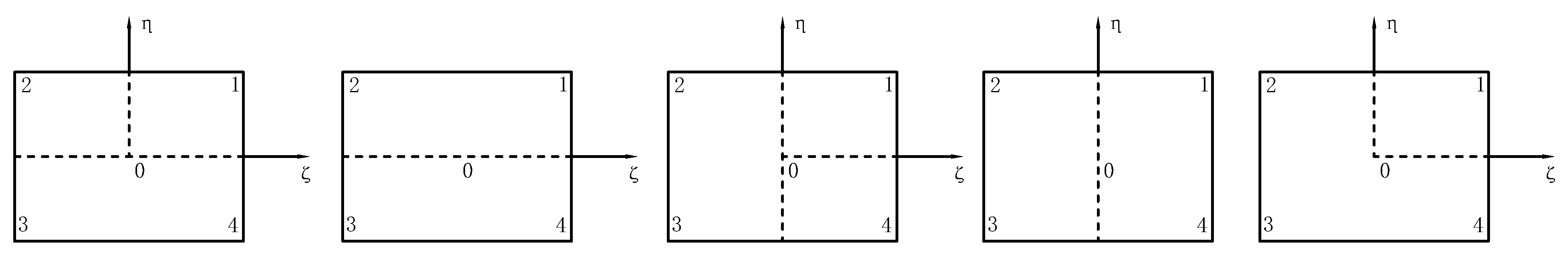
2.1. Degree of Freedom and Displacement Pattern of Element

Besides vertical bending deformations, decks experience deformations along the bridge direction and in the cross-bridge direction; thus, simulation is conducted using the available plate elements. The local coordinate system xoy is positioned at the bottom plate to facilitate the establishment of the deformation coordination conditions. Nodes 1, 2, 3, and 4 are respectively located at the four corner points of the bottom plate, rather than at the four corner points of the middle surface, as shown in Figure 2.
In a local coordinate system, a layered plate with an independent interpolation of displacements and rotation angles has five degrees of freedom, excluding θz (the rotation angle around the z-axis), while the girder elements in the LPGE have six degrees of freedom, including θz. When the stiffness matrix of each element in the local coordinate system is converted to the global coordinate system, θz still needs to be involved so as to derive the uniform stiffness matrix for the plates and girder elements. Each nodal displacement of the layered plate element has six degrees of freedom, i.e., displacements u, v, and w and rotation angles θx, θy, and θz, where θz is the virtual degree of freedom and physically meaningless, i.e.,
δ = δ 1 δ 2 δ 3 δ 4 T
in which, δ i = u i v i w i θ x i θ y i θ z i T , i = 1–4.
Let ζ = x/a, η = y/b, meaning the in-plane coordinates for the underside of the layered plate are described in terms of dimensionless form. As mentioned above, the plate adopts a four-noded rectangular plate element with six degrees of freedom at each node, i.e., three line displacements and three angular displacements. The line and angular displacements are interpolated independently. Like the plain strain element, the interpolation functions of the element adopt a Lagrange polynomial to calculate. Then, using a combination of Mindlin plate element and plane stress element displacement patterns, the displacement at the bottom surface can be expressed as:
f = u ( ζ , η ) v ( ζ , η ) w ( ζ , η ) θ x ( ζ , η ) θ y ( ζ , η ) θ z ( ζ , η ) = i = 1 4 N i u i i = 1 4 N i v i i = 1 4 N i w i i = 1 4 N i θ x i i = 1 4 N i θ y i i = 1 4 N i θ z i
in which Ni is the shape function. It is simplified as: Ni = (1 + ζiζ) (1 + ηiη)/4.
As the displacements and rotation angles are interpolated independently, the displacements and rotation angles within this element are continuous, and so are the displacements and rotation angles of the adjacent elements. Thus, the layered plate element is a C0-type coordinating element.

2.2. Stiffness Matrix for Layered Plate Element

The displacement at any point of the plate is controlled by the in-plane displacement, out-of-plane displacement, and the angular displacement of the bottom surface of the plate, expressed as:
u ( ζ , η , z ) = u 0 ( ζ , η ) z θ x ( ζ , η ) v ( ζ , η , z ) = v 0 ( ζ , η ) z θ y ( ζ , η ) w ( ζ , η , z ) = w 0 ( ζ , η ) θ x ( ζ , η , z ) = θ x ( ζ , η ) θ y ( ζ , η , z ) = θ y ( ζ , η )
Therefore, the strain field of any point on the plate is:
ε = ε 0 + z κ
in which ε0 and κ are the strain field on the bottom plate and field curvature for the plate, respectively. They are given as:
ε 0 = ε x 0 ε y 0 γ x y 0 T = u 0 x v 0 y u 0 y + v 0 x T
When the displacement and rotation angle are interpolated independently, the field curvature of the plate should be expressed as:
κ = κ x κ y κ x y T = θ x x θ y y θ x y θ y x T
Substituting Equation (3) into Equations (5) and (6) gives:
ε = B δ
where
B = [ B 1 B 2 B 3 B 4 ]
B i = B i ( m )   B i ( b )
B i ( m ) = 1 4 a b b ζ i ( 1 + η i η ) 0 0 a η i ( 1 + ζ i ζ ) a η i ( 1 + ζ i ζ ) b ζ i ( 1 + η i η )
B i ( b ) = z 4 a b 0 b ζ i ( 1 + η i η ) 0 0 0 0 a η i ( 1 + ζ i ζ ) 0 0 a η i ( 1 + ζ i ζ ) b ζ i ( 1 + η i η ) 0
in which B, Bi(m), and Bi(b) are the strain matrix, film strain matrix, and bending strain matrix for the plate, respectively. Since the independent nodes are located at the bottom surface instead of the middle surface of the steel plate, Bi(m) and Bi(b) are not strictly a film strain matrix and bending strain matrix.
The bending shear strain is:
γ = w x θ x w y θ y = B s δ
B s = [ B 1 s B 2 s B 3 s B 4 s ]
where
B i s = 1 4 a b 0 0 b ζ i ( 1 + η i η ) a b ( 1 + ζ i ζ ) ( 1 + η i η ) 0 0 0 0 a η i ( 1 + ζ i ζ ) 0 a b ( 1 + ζ i ζ ) ( 1 + η i η ) 0
in which Bs is the bending shear strain matrix for the plate.
When considering shear deformation energy, the total potential energy of the plate is obtained as:
Π * = Π + G t 2 k Ω w x θ x 2 d x d y + G t 2 k Ω w y θ y 2 d x d y
in which Π is the total potential energy of the plate based on the classical small deflection theory, G is the shear modulus of the plate, t is the thickness of the plate, and k is an introduced correction coefficient when the actual non-uniform distribution of shear stress along the thickness direction is considered. According to the principle of shear strain energy, k = 6/5 is taken.
The stiffness matrix of a layered plate element with displacements and angles of rotation interpolating independently is obtained following the principle of minimum potential energy as:
K P = K c + K s
where
K c = ( t s + t c ) t s 1 1 1 1 a b B T D c B d ζ d η d z + G c t c 2 k Ω a b B s T B s d ζ d η
K s = t s 0 1 1 1 1 a b B T D s B d ζ d η d z + G s t s 2 k Ω a b B s T B s d ζ d η
in which the subscript “c” and “s” represent the concrete plate and the steel plate, respectively. B and Bs are shown in Equations (8) and (13), respectively. D is the elastic constitutive matrix for the plate.
Similarly, the stiffness matrix of the beam element is obtained as follows:
K Lx = A Lx 1 1 a B Lx T D Lx B Lx d ζ d A Lx + G Lx A Lx a 2 k 1 Lx 1 1 B Lx s 1 T B Lx s 1 d ζ + G Lx A Lx a 2 k 2 Lx 1 1 B Lx s 2 T B Lx s 2 d ζ
K Ly = A Ly 1 1 b B Ly T D Ly B Ly d ζ d A Ly + G Ly A Ly b 2 k 1 Ly 1 1 B Ly s 1 T B Ly s 1 d η + G Ly A Ly b 2 k 2 Ly 1 1 B Ly s 2 T B Ly s 2 d η
in which the subscript “Lx” represents the girder parallel to the x-axis, while the subscript “Ly” represents the girder parallel to the y-axis.
KLx and KLy are the element stiffness matrix, which is expressed as the nodal displacement at the centroid of the girder end. The combined effect of the girder and the plate is not taken into account.

3. LPGE Composite Action

A concrete bridge ballast deck consists of a number of longitudinal and transverse girders under a steel deck and a concrete ballast slab installed above the deck to develop composite action via headed shear studs. An LPGE composed of longitudinal and transverse girders, concrete plate, and steel plate is proposed to investigate the mechanical behavior of a concrete composite bridge with ballast deck, as shown in Figure 3. The top plate is a concrete plate and the bottom plate is a steel plate. Two steel girders are arranged below the bottom plate. The local coordinate system xoy surface is set at the bottom surface of the steel plate; the nodes 1, 2, 3, and 4 are located at the four corner points of the bottom surface. “·”denotes the position of the nodes.
The nodal degrees of freedom of the LPGE are the same as those of the layered plate in Section 2.1 (i.e., three line displacements and three angular displacements). The plate element used in the LPGE is constructed using the same displacement pattern as the layered plate in Section 2.1, that is, using Lagrangian polynomials.

3.1. Girder Element Constraint Matrix

In the girder element parallel to the x-axis, every node has six degrees of freedom as:
δ Lx i = [ u Lx i v Lx i w Lx i θ Lx x i θ Lx y i θ Lx z i ] T
in which the superscript “Lx” represents the girder parallel to the x-axis.
However, in the LPGE, the degree of freedom θzi related to the girder element θLxzi is the virtual degree of freedom. To create the deformation coordination conditions between the plate element and the girder element parallel to the x-axis, θLxzi can be obtained through the rotation along the tangent of the boundary within the bottom surface of the plate, which is given as:
θ Lx z = u y
It is assumed that the displacements and deformations of the steel deck and girder at the interface satisfy the following conditions:
(1)
The normal line at the base on the steel plate crossing the junction point of the girder and plate before deformation is in a straight line, and the straight line remains unchanged after deformation;
(2)
Before deformation, the deck including the cross-sectional area of the boundary and the section of the girder element passing through the point (including this normal line) is defined in a plane. It remains in the same plane after deformation.
It is noted that the displacements of the girder nodes and the steel plate nodes exhibit the following relationship according to the deformation coordination conditions for steel plates and girder elements above:
u Lx t = u b | η = 0 v Lx t = v b | η = 0 w Lx t = w b | η = 0 θ Lx x = θ x | η = 0 θ Lx y = θ y | η = 0 θ Lx z = θ z | η = 0 = u y | η = 0
in which the superscript “t” represents the top of the girder, while the superscript “b” represents the bottom of the steel plate.
Based on the above hypothesis, the displacements of the girder nodes can be expressed as:
δ Lx = 0 L Lx 1 L Lx 2 0 L Lx 1 0 0 L Lx 2 δ 1 δ 2 δ 3 δ 4 = L Lx δ
in which
L Lx 1 = 1 2 0 0 h Lxc 2 0 0 0 1 2 0 0 h Lxc 2 0 0 0 1 2 0 0 0 0 0 0 1 2 0 0 0 0 0 0 1 2 0 1 2 b 0 0 0 0 0
L Lx 2 = 1 2 0 0 h Lxc 2 0 0 0 1 2 0 0 h Lxc 2 0 0 0 1 2 0 0 0 0 0 0 1 2 0 0 0 0 0 0 1 2 0 1 2 b 0 0 0 0 0
in which LLx denotes the constraint matrix for the girder parallel to the x-axis and the layered plate, and hLxc denotes the distance from the girder centroid to the girder top.
Similarly, the constraint matrix for the girder parallel to the y-axis and the layered plate is obtained as follows:
L Ly = 0 0 L Ly 1 L Ly 2 L Ly 2 L Ly 1 0 0
in which the superscript “Ly” represents the girder parallel to the y-axis.
While considering the composite action of the girder and the plate, the girder element stiffness matrix is converted as follows:
K Lx * = L Lx T K Lx L Lx
K Ly * = L Ly T K Ly L Ly

3.2. LPGE Stiffness Matrix

The stiffness matrix for the layered plate element and girder element are derived respectively in the previous section. The stiffness matrix of the LPGE under the combined action of the plate and girder is derived by using the above obtained matrices.
The element stiffness matrix of the LPGE in the local coordinate system can be obtained by superimposing the stiffness of the layered plate and girder element considering the combined action of the plate and girders:
K PL = K P + K Lx * + K Ly *
It is necessary to employ different types of LPGE to simulate certain areas of the deck system, such as the connection zone of the lower chord member of the side joist and the transverse girder, the connection zone between the lower chord of the side truss and the girder, and the position of the plate where there is only one girder, as shown in Figure 4. When computing the stiffness matrix of those elements, some adjustments are required to be made accordingly in the ζ or η integration interval in the girder element.

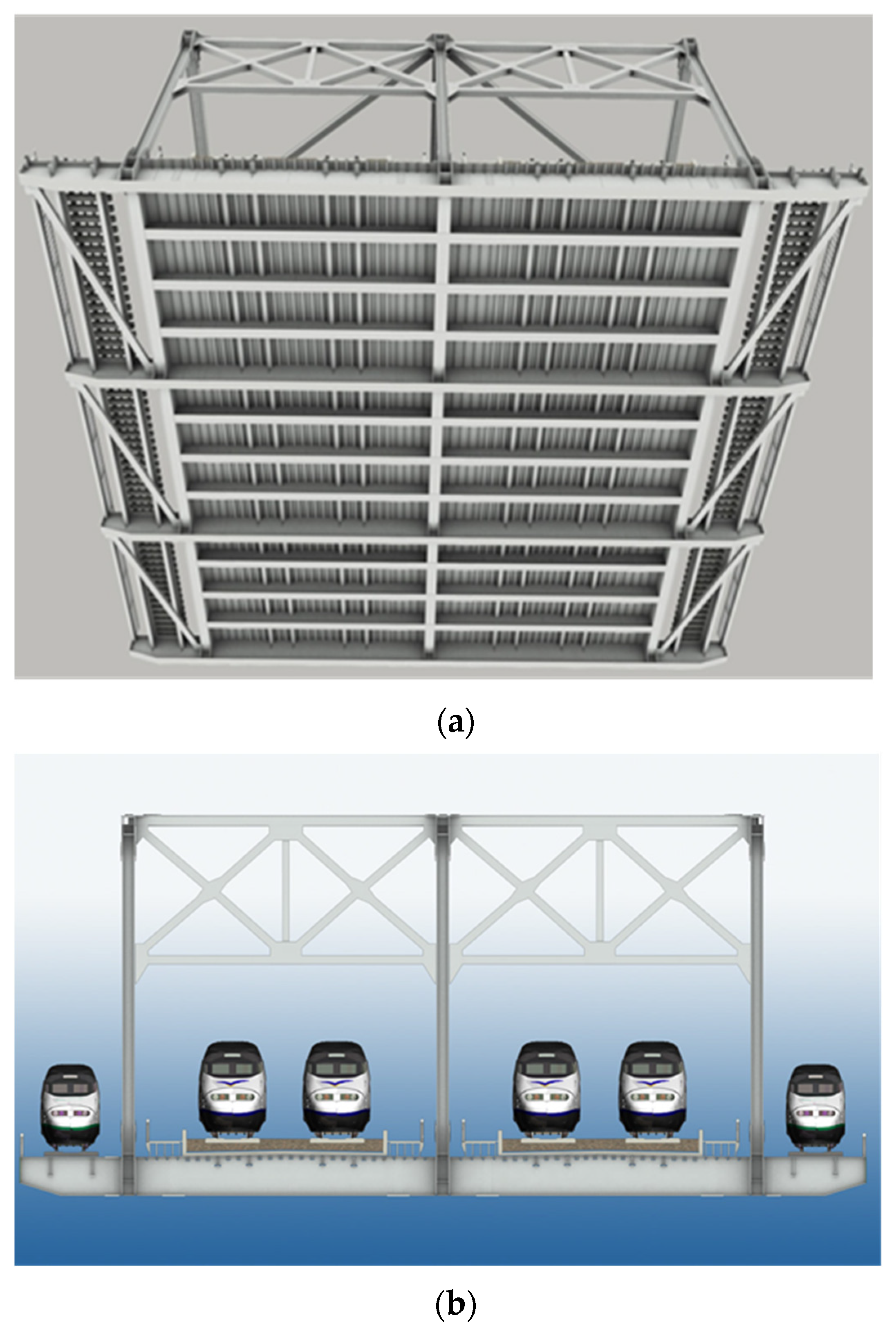
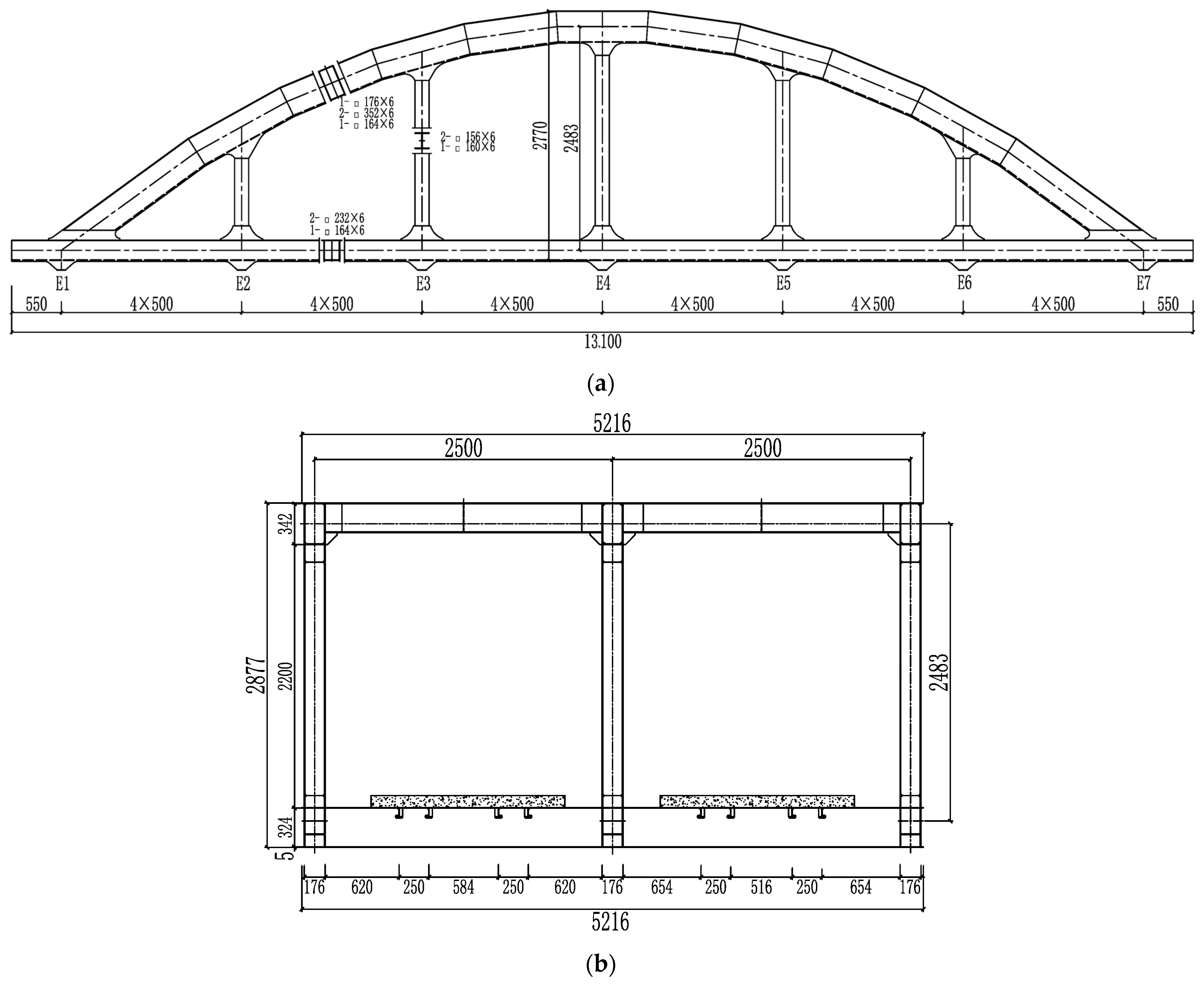
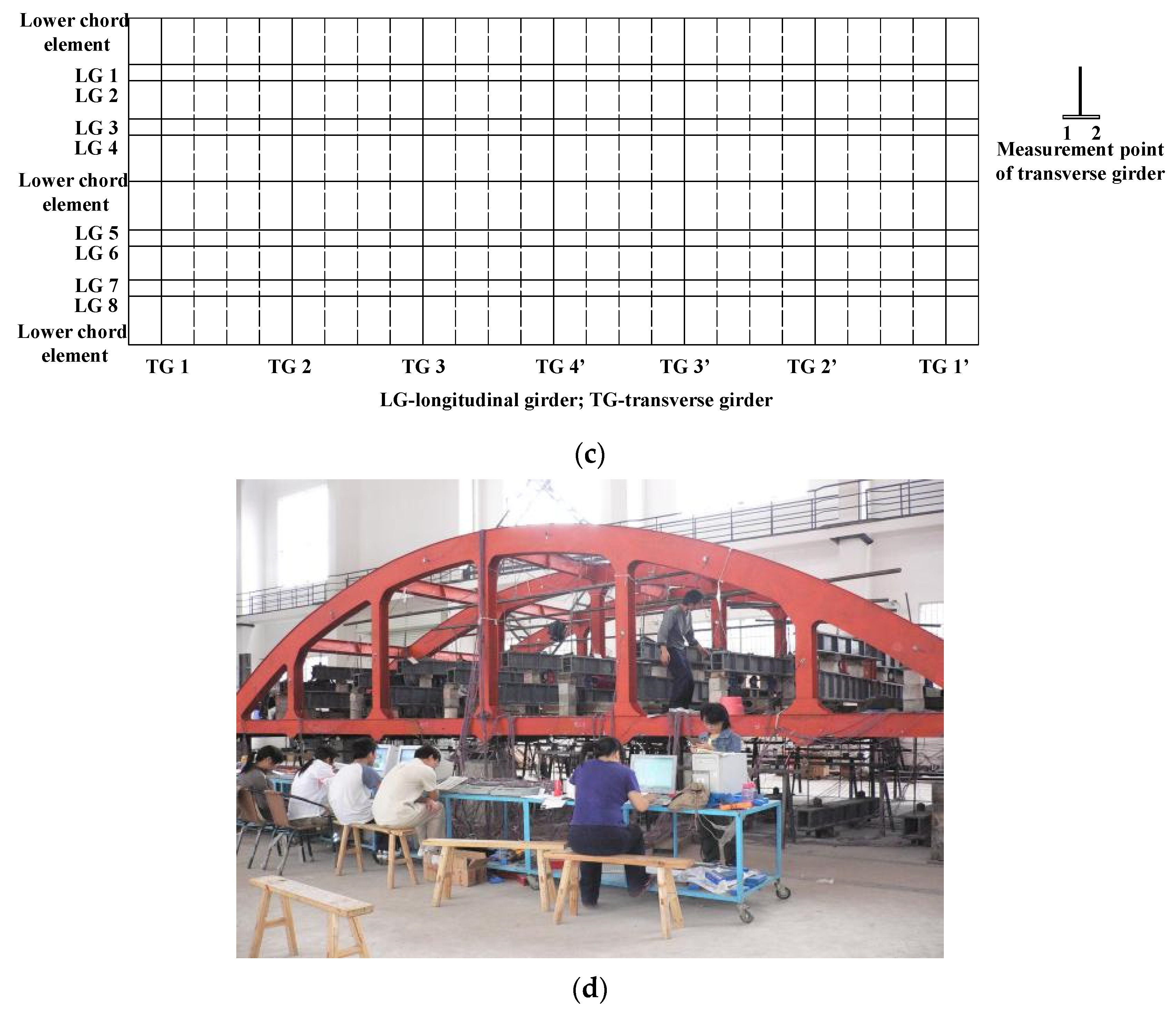
4. Engineering Application

A model test is performed to study the behavior of the steel–concrete composite decks. The correctness of the LPGE method is proven. An arch model for a three-truss bridge with six panels is constructed according to the scale ratio 1:6 of the real bridge structure, as shown in Figure 5. The length of the joint is 2 m, the height of the truss 2.77 m, and the rise–span ratio 1/4.8. The deck adopts the concrete bridge ballast deck. The whole steel deck adopts a multi-girder system with one main transverse girder and three small transverse girders arranged in every panel along the bridge direction. The main transverse girder is connected to the main truss at the main truss node, and the small transverse girder is welded to the lower chord element of the main truss. In the cross direction of the steel deck, two inverted T-shaped longitudinal girders are welded under every track. The concrete ballast trough is arranged above the steel deck with a thickness of 100 mm. In the test, the jack loading method is used.
In this method, the load is imposed on the deck and joints separately so as to accurately simulate the stress state of the real bridge under the action of dead load and live load (see Figure 5d).
Figure 5. Arch segment model: (a) elevation view of the model (unit: mm); (b) mid-span cross section (unit: mm); (c) layout of the deck system; (d) arch segment in the model.
Applsci 13 06545 g005aApplsci 13 06545 g005b
The LPGE is introduced into the general software after improvements to analyze and compute the test model. The computation results, the results obtained by ANSYS in the plate beam model, and the measured result for the model test are compared as shown in Figure 6, Figure 7, Figure 8, Figure 9, Figure 10, Figure 11, Figure 12 and Figure 13. The deck is simulated by the ANSYS general plate element, while the longitudinal and transverse girders and the stiffeners of the deck are simulated by the beam element, and the main trusses are simulated by the beam element (hereinafter referred to as the ANSYS plate beam model). The number of longitudinal and transverse girders is shown in Figure 5c.
As seen from Figure 6, Figure 7, Figure 8 and Figure 9, the difference in the stress between point 1 and point 2 on the transverse girders is not significant. It indicates that the load caused by the bending moment outside the transverse girder surface is less prominent. This is attributed to the fact that the composite deck connects the upper flange of the longitudinal girders, transverse girders, and lower chord members, reducing the transverse deformation of the transverse girders and improving the stress of the transverse girders. Thus, the expansion of the longitudinal girders that are arranged to reduce the lateral deformation of the transverse girders is avoided, and the driving conditions on high-speed roads are greatly improved. It is seen from Figure 10, Figure 11, Figure 12 and Figure 13 that the difference in the stress of the longitudinal girders between the panels is not prominent and the stress is distributed relatively uniformly. The concrete ballast slab bears a greater tensile stress above the transverse girders, where broken seams in the concrete ballast slab are arranged to improve the concrete stress.
For the ANSYS method, modeling for the plate element and the beam element needs to be conducted separately. The coupling displacement between the plate elements and the beam elements is used to simulate their combined action. The modeling process is complex with low computation efficiency. Moreover, the deformation coordination between the plate elements and the beam elements cannot be guaranteed since the displacement patterns of the plate elements and the beam elements are different, and the accuracy of the computation is low. From the above results, it is observed that the computation results produced using the ANSYS method are larger than those obtained using the LPGE method. This is attributed to the uncoordinated deformation between the plate elements and beam elements in the ANSYS model. The LPGE method combines the plate element and the girder element into one element to conveniently construct the model with high efficiency. The displacement pattern of the LPGE adopts the independent interpolation of the displacement and rotation angle. It ensures the deformation coordination between the plate and the girder on the interface. LPGE is a C0-type coordinating element. The computation results produced are highly accurate. It is indicated that the computation results produced using the LPGE method are in good agreement with the measured results. LPGE is proven to be an effective method with the results obtained being more accurate.

5. Conclusions

In this paper, an LPGE is proposed in constructing a finite element model for a steel–concrete composite deck. The plate girder constraint matrix and element stiffness matrix are derived. The LPGE method is applied for the analysis and computation of the composite deck. The results obtained by ANSYS are compared with test results to verify its correctness and effectiveness. The conclusions of this study are as follows:
(1)
The LPGE combines multi-layer plates made of different materials with longitudinal and transverse girders in one element. In this way, the model is conveniently constructed with fewer elements involved, and computation is very efficient. It is particularly desirable to apply the approach to a steel–concrete composite deck structure made of one or more different building materials.
(2)
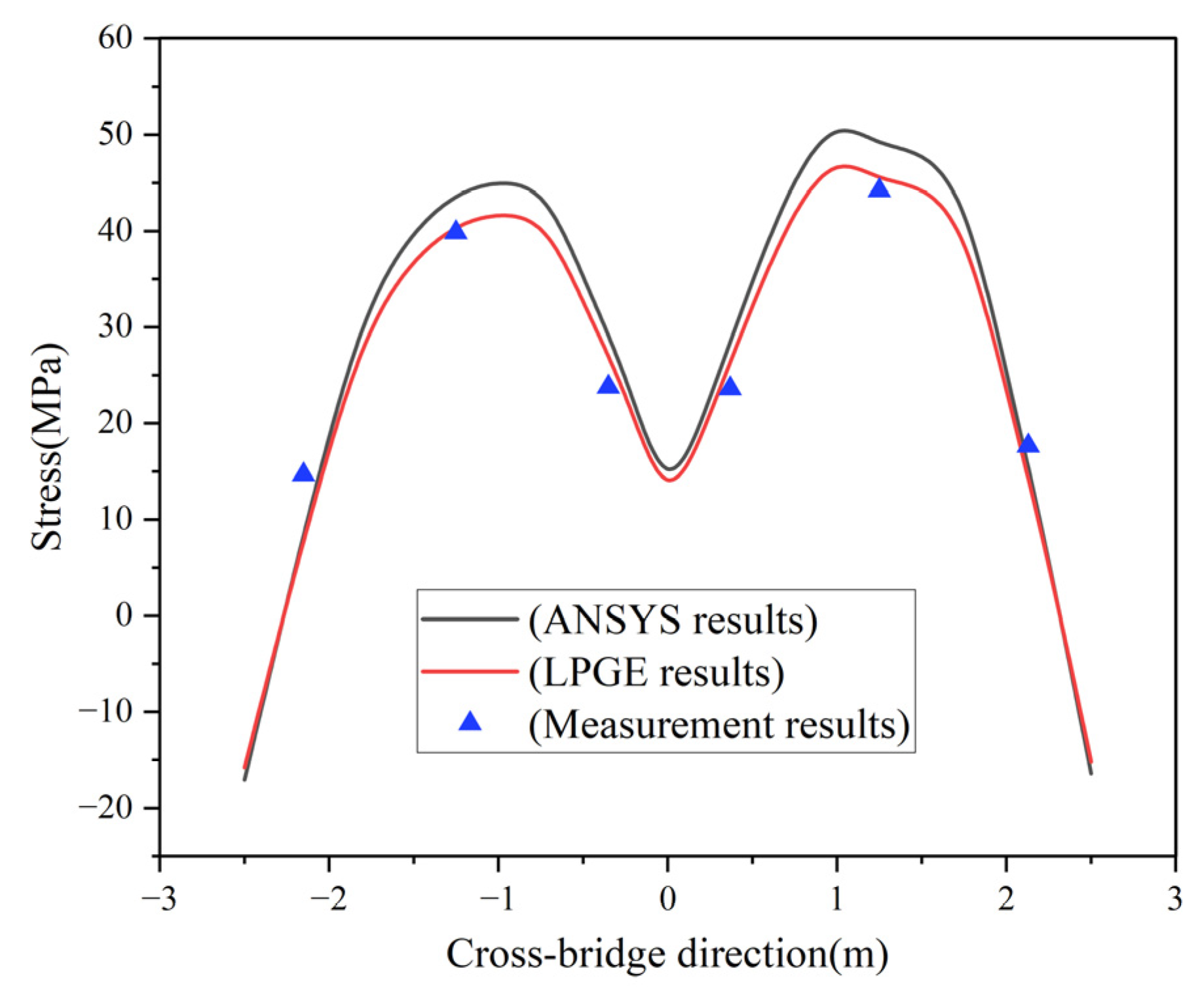
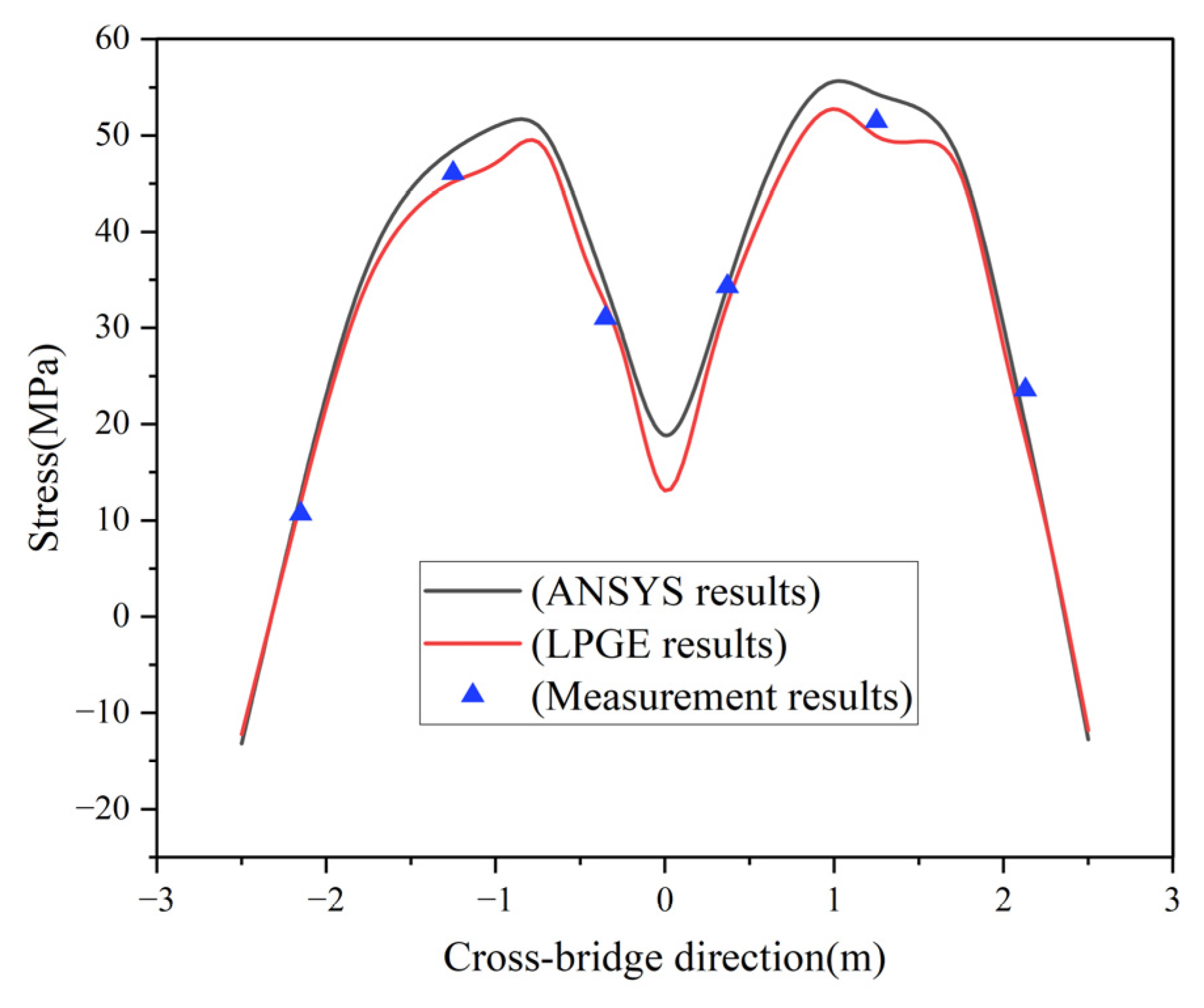
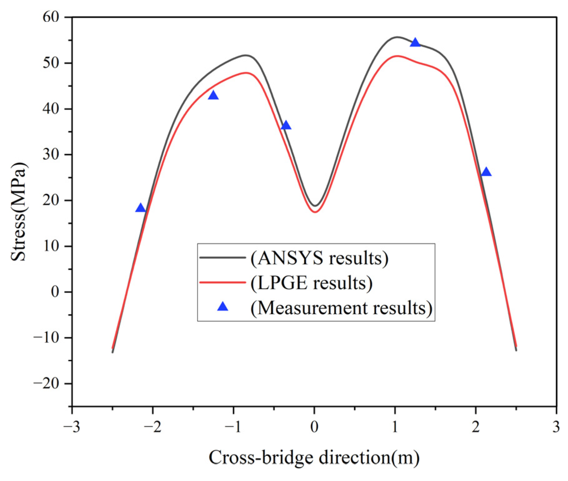
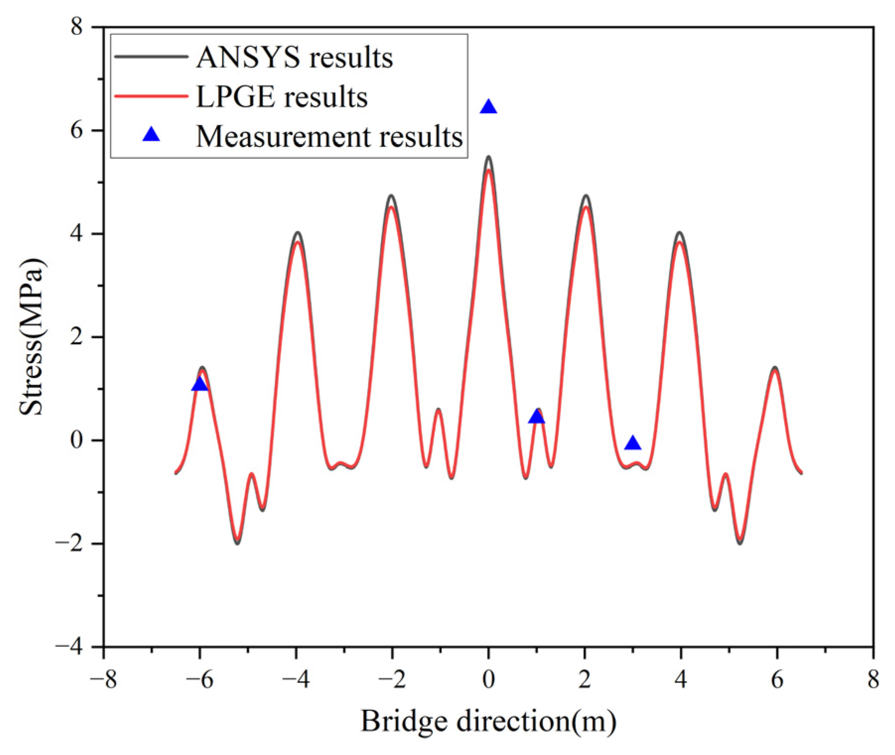
Compared with the ANSYS plate beam model, LPGE, as a C0-type coordinating element, ensures the deformation coordination between plates, and between plates and girders at the interface while considering the shear deformation. It provides highly accurate computation results.
(3)
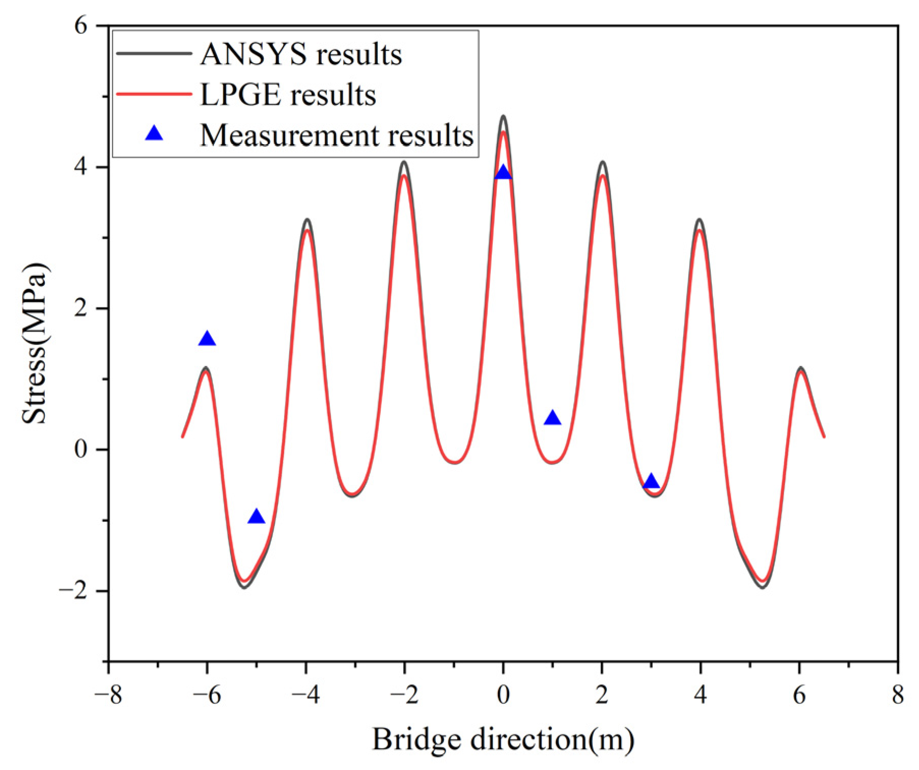
The computation results produced by the LPGE are in good agreement with those of the ANSYS plate beam model and model test. The LPGE is proven to be an effective method, with the results obtained being more accurate.

Author Contributions

Methodology, Y.H.; validation, W.H. and L.C.; writing—original draft preparation, Y.H.; writing—review and editing, Y.H. All authors have read and agreed to the published version of the manuscript.

Funding

This research received no external funding.

Institutional Review Board Statement

Not applicable.

Informed Consent Statement

Not applicable.

Data Availability Statement

The data are contained within the article. The data presented in this study are available on request from the corresponding author.

Conflicts of Interest

The authors declare no conflict of interest.

References

  1. Shangguan, B.; Hu, H.Y.; Ning, P.H.; Su, Q.T. Mingzhuwan bridge: The largest span three-main-truss steel arch bridge. Struct. Eng. Int. 2023, 33, 89–95. [Google Scholar] [CrossRef]
  2. Qin, S.Q.; Gao, Z.Y. Developments and prospects of long-span high-speed railway bridge technologies in China. Engineering 2017, 3, 787–794. [Google Scholar] [CrossRef]
  3. Gao, Z.Y.; Yi, L.X.; Xiao, H.Z. Dashengguan bridge-the largest span steel arch bridge for high-speed railway. Struct. Eng. Int. 2010, 20, 299–302. [Google Scholar] [CrossRef]
  4. Zhao, H.W.; Ding, Y.L.; Nagarajaiah, S.; Li, A.Q. Longitudinal displacement behavior and girder end reliability of a jointless steel-truss arch railway bridge during operation. Appl. Sci. 2019, 9, 2222. [Google Scholar] [CrossRef]
  5. Zhang, X.M.; Wang, A.W.; Chen, W.M. Large deformation beam-slab element of eccentric stiffened plate. J. Nav. Eng. Univ. 2000, 3, 31–34. [Google Scholar]
  6. Wu, X.; Wu, T.T.; Chen, W.Z. Analysis of height difference between three trusses of a steel truss bridge during incremental launching. Stahlbau 2018, 87, 910–922. [Google Scholar] [CrossRef]
  7. Tan, Y.L.; Zhu, B.; Yan, T.Y.; Huang, B.; Wang, X.W.; Yang, W.W.; Huang, B. Experimental study of the mechanical behavior of the steel-concrete joints in a composite truss bridge. Appl. Sci. 2019, 9, 854. [Google Scholar] [CrossRef]
  8. Hou, W.Q.; Ye, M.X. Design methods of headed studs for composite decks of through steel bridges in high-speed railway. J. Cent. South Univ. Technol. 2011, 18, 946–952. [Google Scholar] [CrossRef]
  9. Han, Y.Q.; Ye, M.X. Mechanical characteristics of three-truss plate-truss composite bridges on high-speed railways. Appl. Mech. Mater. 2014, 590, 358–362. [Google Scholar] [CrossRef]
  10. Chen, K.L.; Wang, R.H.; Huang, Y.H.; Cai, L.R. Study on spatial calculation method of three-girder continuous slab-truss composite bridge. Civ. Eng. Environ. Eng. 2011, 33, 32–37. [Google Scholar]
  11. Zeng, Y.; Zheng, H.J.; Jiang, Y.H.; Ran, J.H.; He, X. Modal analysis of a steel truss girder cable-stayed bridge with single tower and single cable plane. Appl. Sci. 2022, 12, 7627. [Google Scholar] [CrossRef]
  12. Xing, Y.H.; Wang, W.Y.; Ou, Y.; Jiang, X.C.; Al-azzani, H. Seismic behavior of steel truss and concrete composite shear wall with double x-shaped braces. J. Build. Eng. 2022, 62, 105399. [Google Scholar] [CrossRef]
  13. Han, J.H.; Shu, G.P.; Qin, Y.; Zhou, G.G.; Zhou, X.L. Experimental seismic behavior of double skin composite wall with steel truss. J. Constr. Steel Res. 2021, 180, 106569. [Google Scholar] [CrossRef]
  14. Kaminski, M.; Błonski, R. Analytical and numerical reliability analysis of certain pratt steel truss. Appl. Sci. 2022, 12, 2901. [Google Scholar] [CrossRef]
  15. Kumar, Y.V.S.; Mukhopadhyay, M. Finite element analysis of ship structures using a new stiffened plate element. Appl. Ocean. Res. 2000, 22, 361–374. [Google Scholar] [CrossRef]
  16. Jaksic, N.; Greuner, H.; Herrmann, A. Fem investigation and thermo-mechanic tests of the new solid tungsten divertor tile for asdex upgrade. Fusion Eng. Des. 2013, 88, 1789–1792. [Google Scholar] [CrossRef]
  17. Chen, Y.J.; Sun, H.L.; Feng, Z.F. Study on seismic isolation of long span double deck steel truss continuous girder bridge. Appl. Sci. 2022, 12, 2567. [Google Scholar] [CrossRef]
  18. Innocenzi, R.D.; Nicoletti, V.; Arezzo, D.; Carbonari, S.; Gara, F.; Dezi, L. A Good Practice for the Proof Testing of Cable-Stayed Bridges. Appl. Sci. 2022, 12, 3547. [Google Scholar] [CrossRef]
  19. Nicoletti, V.; Arezzo, D.; Carbonari, S.; Dezi, F.; Gara, F. Measurements of ambient vibrations for a cable-stayed bridge including the soil-foundation system. In Proceedings of the 11th International Conference on Structural Dynamics, EURODYN, Athens, Greece, 23–26 November 2020; Volume 1, pp. 1722–1730. [Google Scholar]
  20. Zhu, Q.; Wang, H.; Zhu, X.; Spencer, B.F., Jr. Investigation on the pattern for train-induced strains of the long-span steel truss railway bridge. Eng. Struct. 2022, 275, 115268. [Google Scholar] [CrossRef]
  21. Cheng, J.; Xu, M.S.; Xu, H. Mechanical performance study and parametric analysis of three-tower four-span suspension bridges with steel truss girders. Steel Compos. Struct. 2019, 32, 189–198. [Google Scholar]
  22. Xu, Y.; Zeng, Z.; Wang, Z.; Yan, H. Seismic study of a widened and reconstructed long-span continuous steel truss bridge. Struct. Infrastruct. Eng. 2020, 17, 191–201. [Google Scholar] [CrossRef]
  23. Liang, L.; Li, X.Z.; Sun, Y.D.; Gong, Z.H.; Bi, R. Measurement research on vibro-acoustic characteristics of large-span plate-truss composite bridge in urban rail transit. Appl. Acoust. 2022, 187, 108518. [Google Scholar] [CrossRef]
  24. Oñate, E. Structural Analysis with the Finite Element Method Linear Statics; Springer: Berlin/Heidelberg, Germany, 2013. [Google Scholar]
  25. Neto, M.A.; Amaro, A.; Cirne, L.R.J.; Leal, R. Engineering Computation of Structures the Finite Element Method; Springer: Cham, Switzerland, 2015. [Google Scholar]
  26. Wang, R.H.; Zeng, Q.Y.; Wang, H.L. Nonlinear finite element analysis of steel plate-truss composite beams. J. Civ. Eng. 2000, 33, 56–62. [Google Scholar] [CrossRef]
  27. Chen, Y.J.; Ye, M.X. A plate-girder composite element suitable for the calculation of through steel truss composite bridges. J. Comput. Mech. 2006, 23, 229–234. [Google Scholar]
  28. Sun, Q.k.; Zhang, N.; Liu, X. A numerically stable exact method for analysis of partial-interaction composite beams based on timoshenko beam theory. Eng. Struct. 2022, 273, 115049. [Google Scholar] [CrossRef]
  29. Angoshtari, A. Finite Element Methods in Civil and Mechanical Engineering: A Mathematical Introduction; CRC Press: Boca Raton, FL, USA, 2021. [Google Scholar]
  30. Baccouch, M. Finite Element Methods and Their Applications; IntechOpen: London, UK, 2021. [Google Scholar]
Figure 2. Layered plate element.
Applsci 13 06545 g002
Figure 3. LPGE chart.
Applsci 13 06545 g003
Figure 4. Other types of LPGE.
Applsci 13 06545 g004
Figure 6. Normal stress of transverse girder 2 at point 1 along the cross-bridge direction.
Applsci 13 06545 g006
Figure 7. Normal stress of transverse girder 2 at point 2 along the cross-bridge direction.
Applsci 13 06545 g007
Figure 8. Normal stress of transverse girder 4 at point 1 along the cross-bridge direction.
Applsci 13 06545 g008
Figure 9. Normal stress of transverse girder 4 at point 2 along the cross-bridge direction.
Applsci 13 06545 g009
Figure 10. Normal stress of longitudinal girder 4 along the bridge direction.
Applsci 13 06545 g010
Figure 11. Normal stress of longitudinal girder 8 along the bridge direction.
Applsci 13 06545 g011
Figure 12. Normal stress of the top surface of the concrete slab above longitudinal girder 1 along the bridge direction.
Applsci 13 06545 g012
Figure 13. Normal stress of the top surface of the center line of the side concrete slab along the bridge direction.
Applsci 13 06545 g013
Disclaimer/Publisher’s Note: The statements, opinions and data contained in all publications are solely those of the individual author(s) and contributor(s) and not of MDPI and/or the editor(s). MDPI and/or the editor(s) disclaim responsibility for any injury to people or property resulting from any ideas, methods, instructions or products referred to in the content.

