
Deformation Response of a Pipeline to Nearby Deep Foundation Pit Excavation: Numerical Simulations and Field Tests
Abstract
:1. Introduction
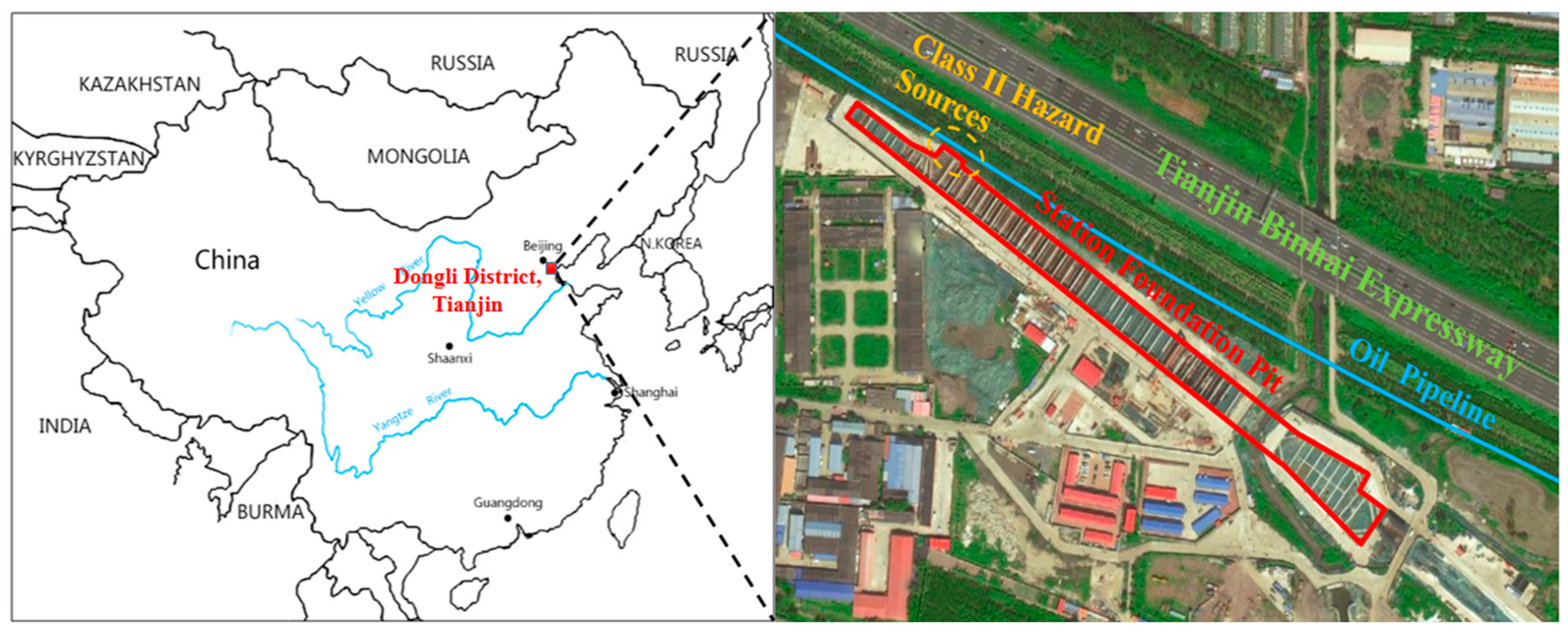
2. Project Overview
2.1. Tianjin Metro Station
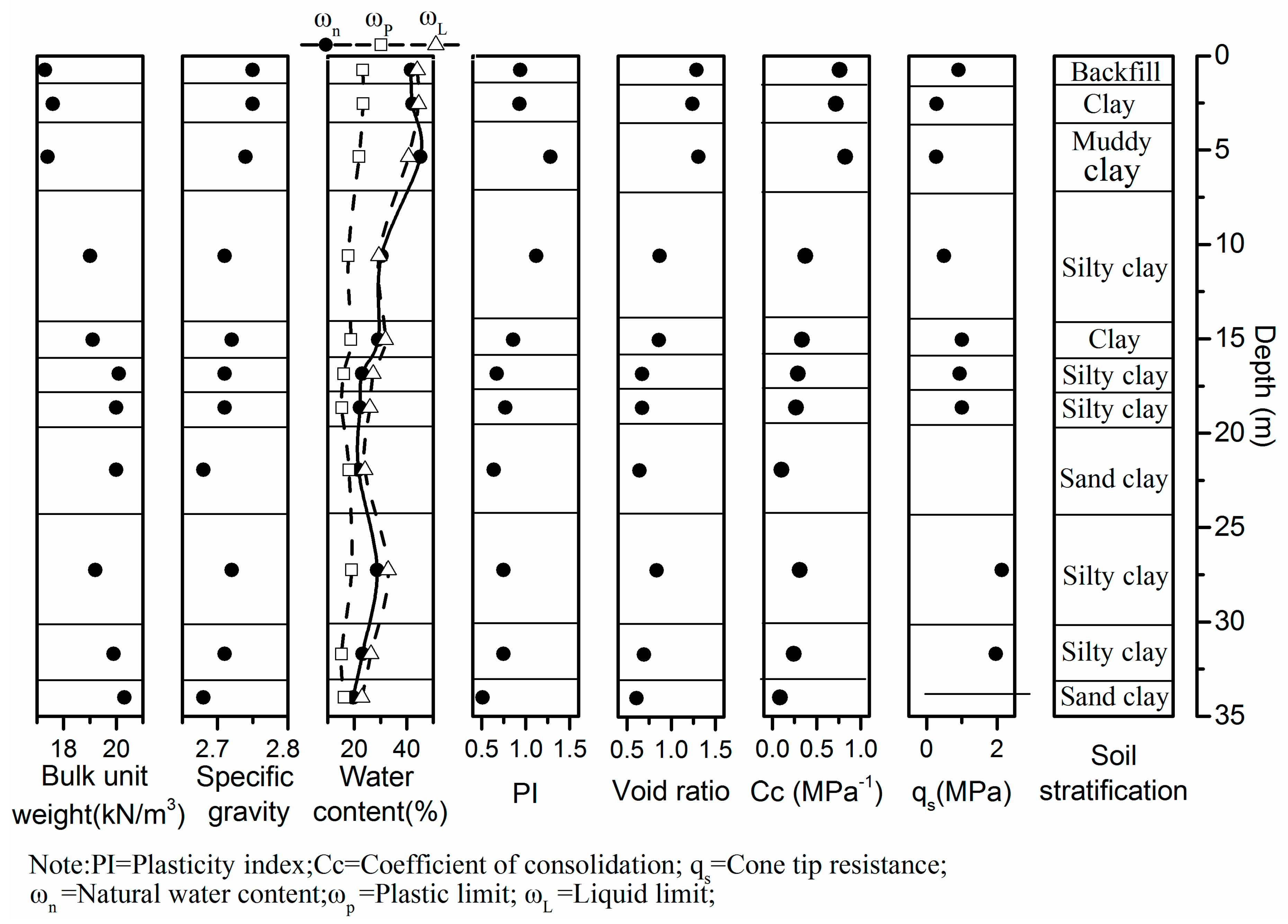
2.2. Engineering Geology
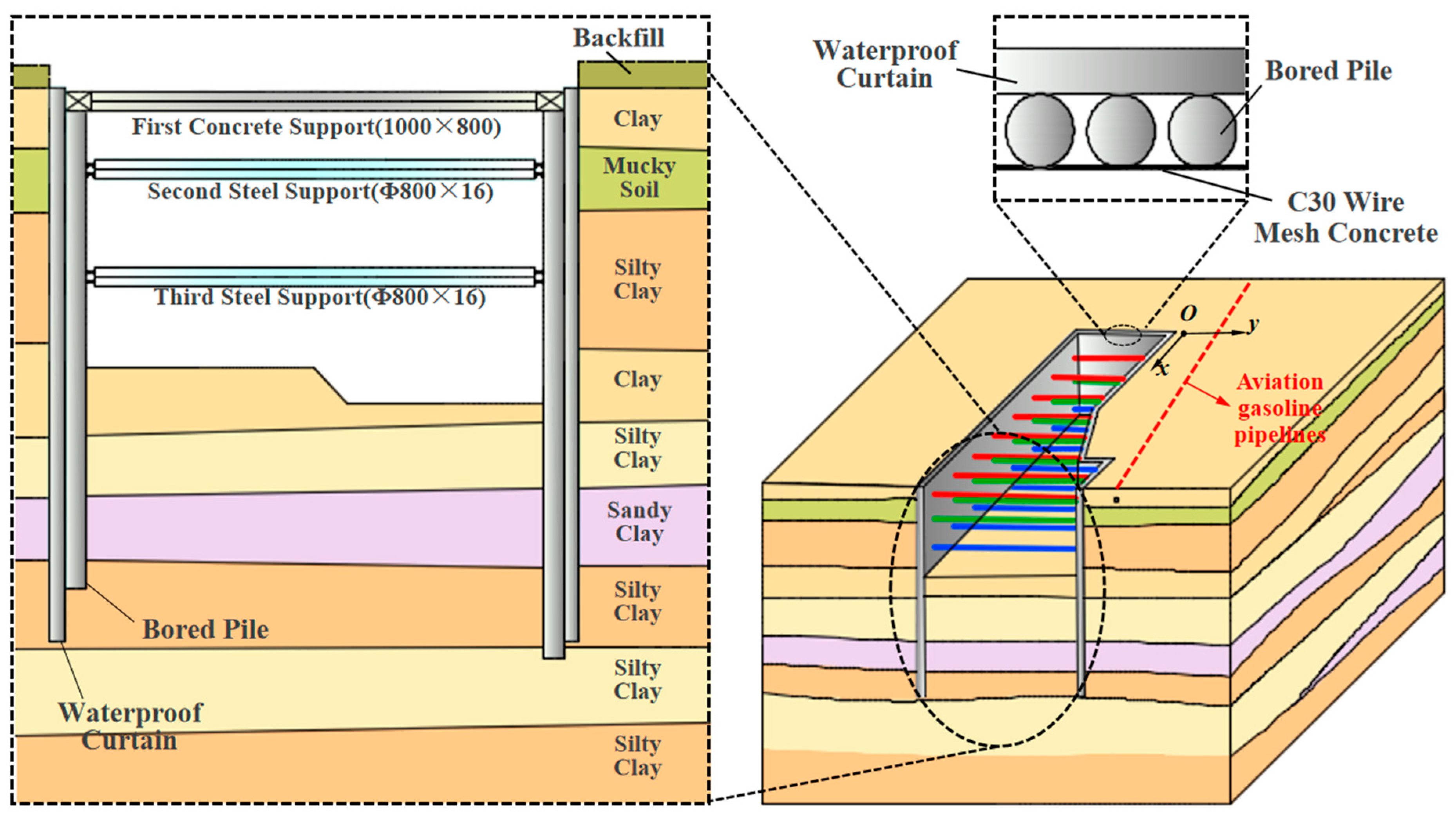
2.3. Supporting Method
3. Numerical Simulation
3.1. Excavation Method
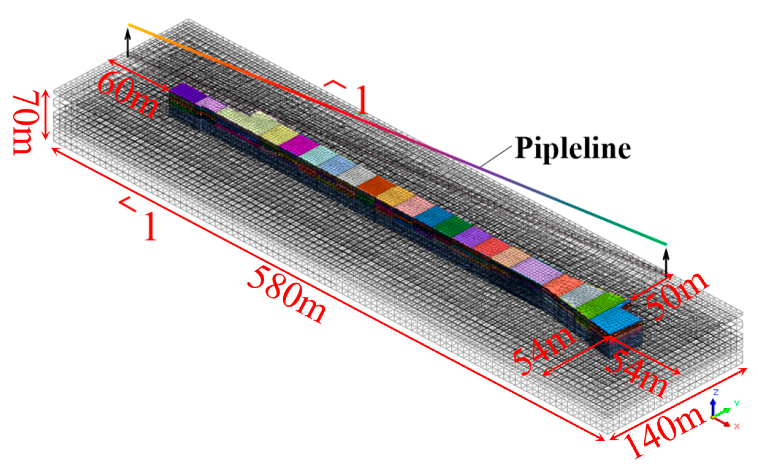
3.2. Numerical Model
- (1)
- The influence of time on soils is not considered during the excavation of foundation pit.
- (2)
- When the station foundation pit is excavated, the foundation pit dewatering has been completed. Water permeability is not considered separately.
- (3)
- The pressure of the liquid inside the aviation oil pipeline on the pipeline body is directly replaced by area load.
- (4)
- Contact surface parameters are not set between materials at different strata. There is no relative slip between materials at different strata, and their displacement is coordinated.
- (5)
- The initial stress field covers gravity stress.
3.3. Result Analysis
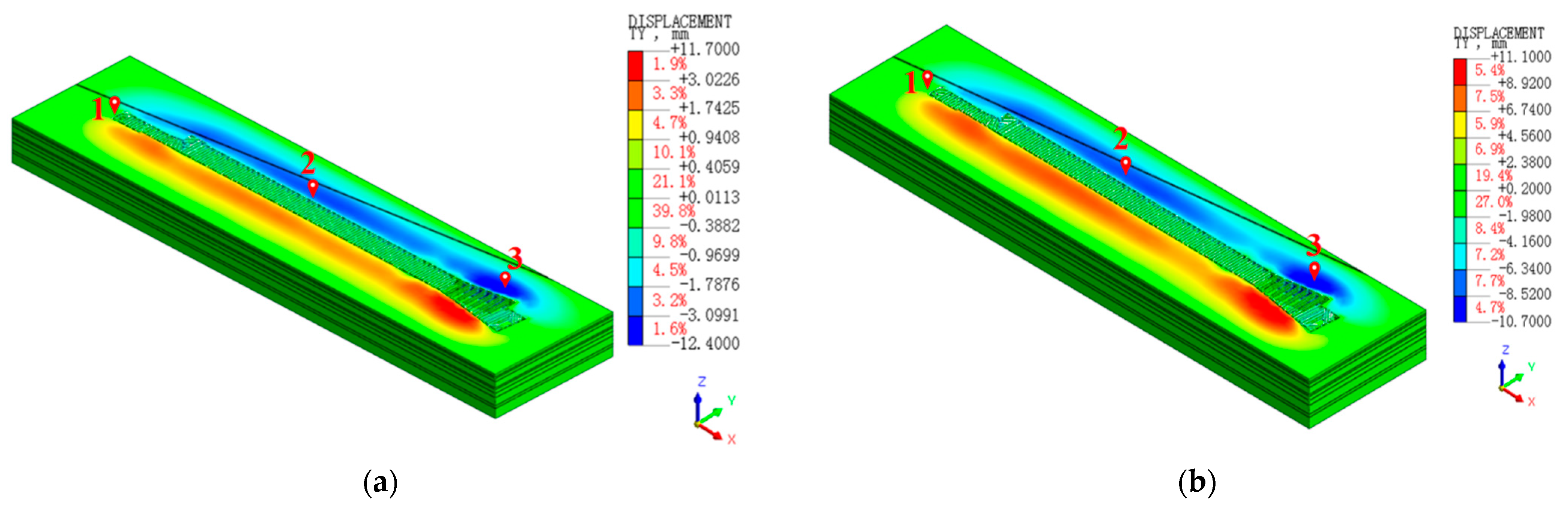
3.3.1. Deformation of Adjacent Soil
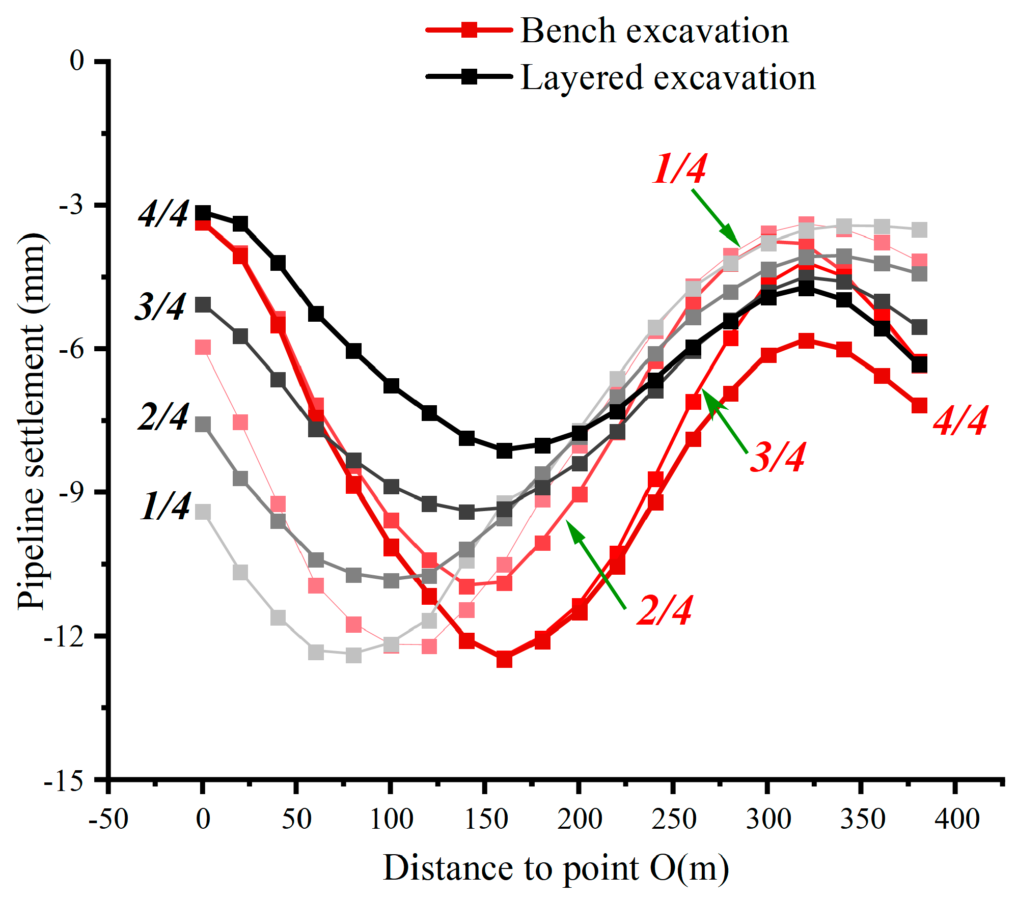
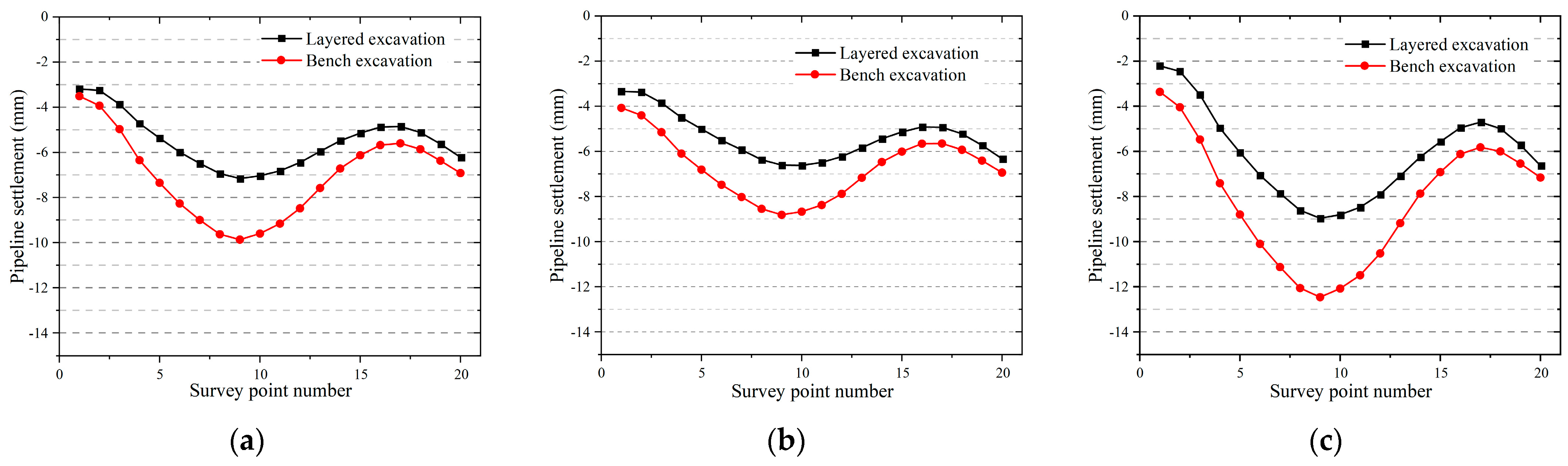
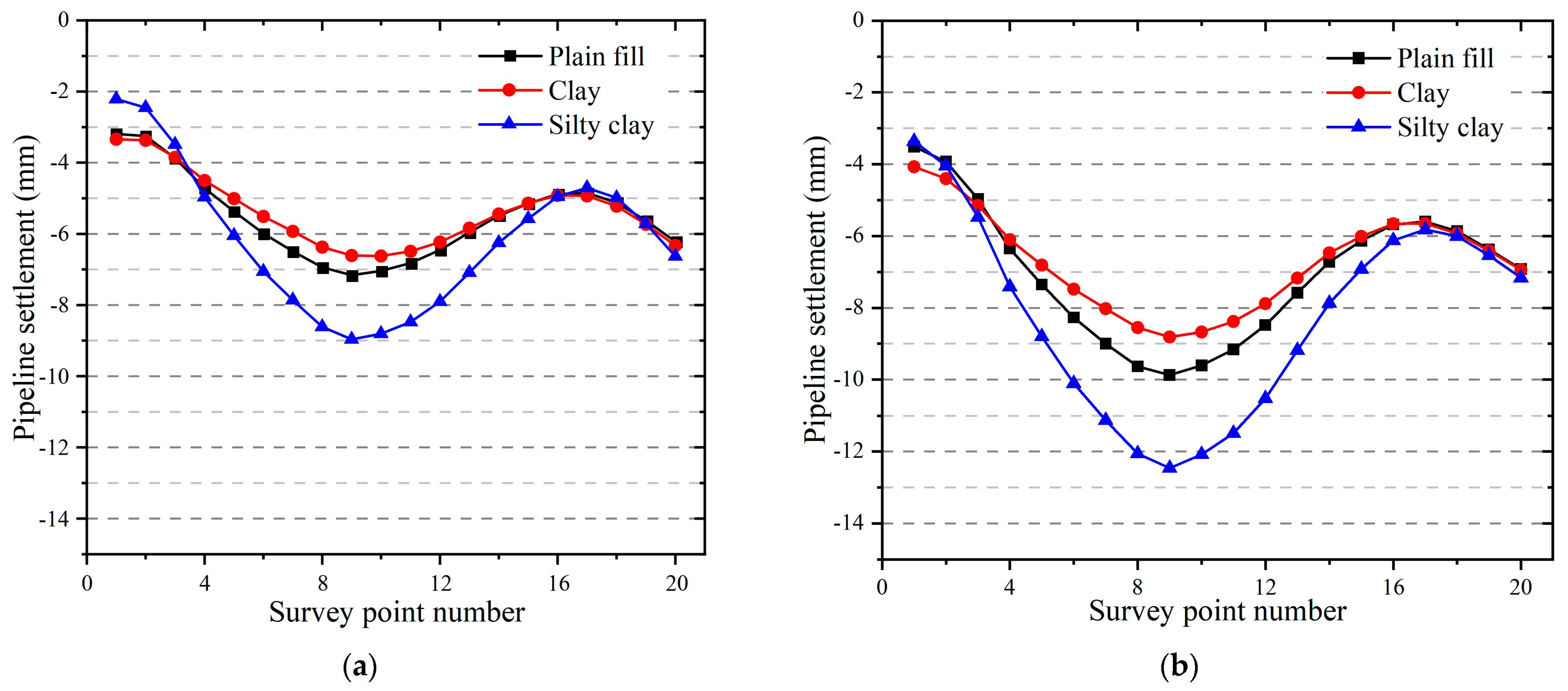
3.3.2. Pipeline Settlement Analysis
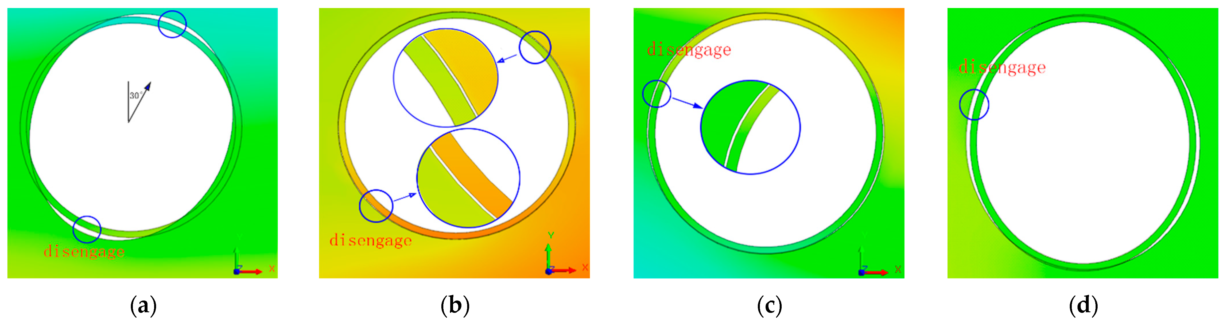
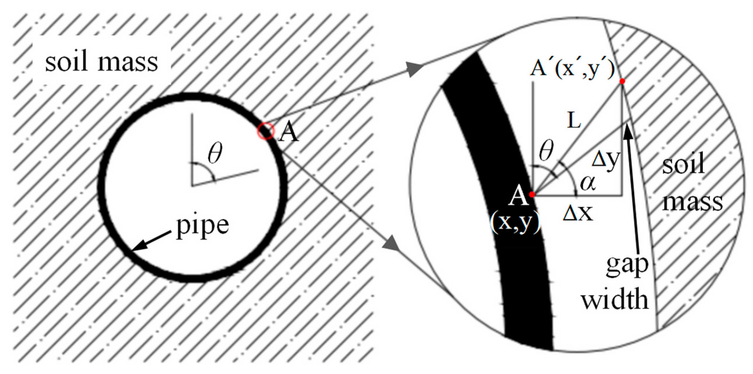
3.3.3. Analysis of Pipeline-Soil Interaction
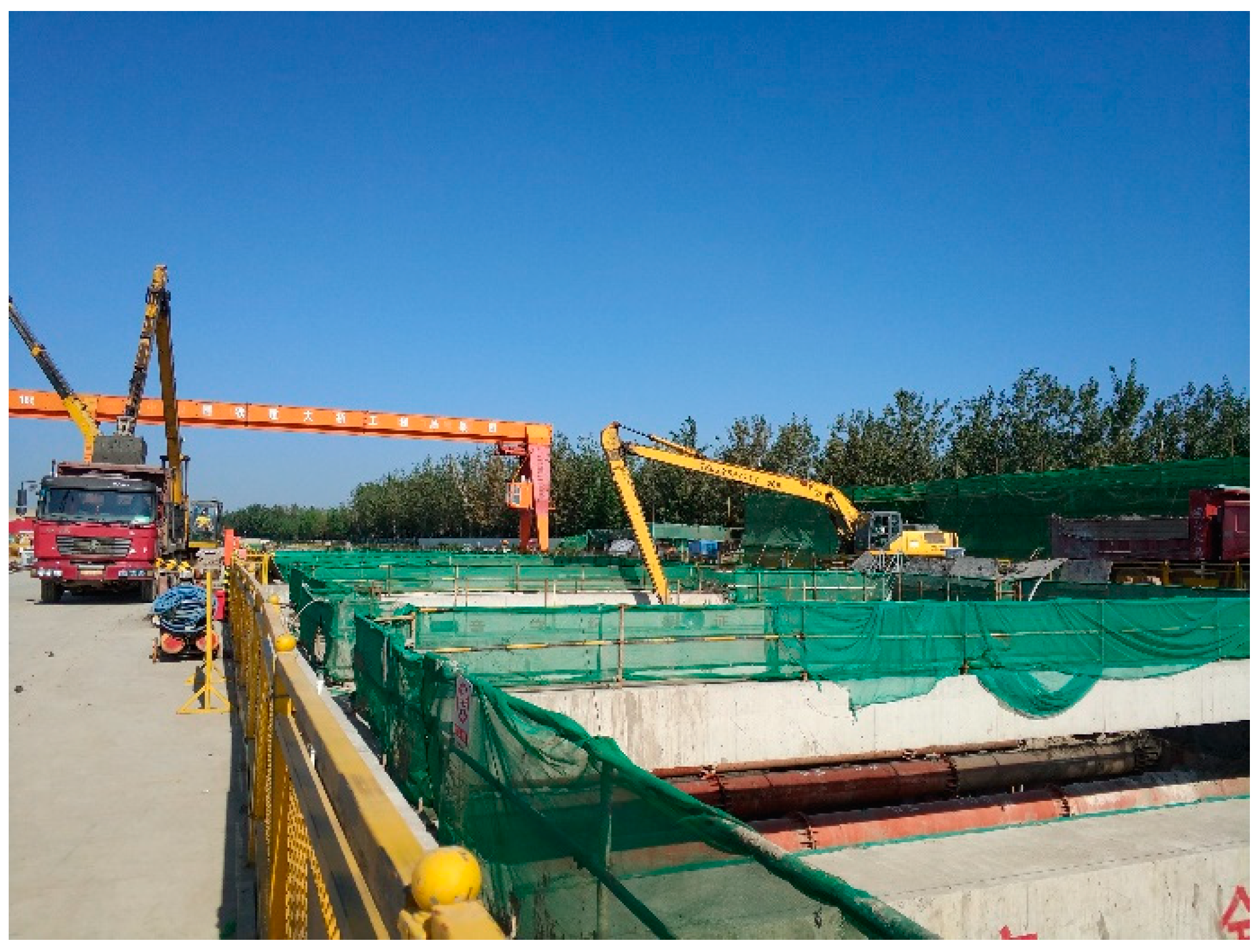
4. Field Test and Validation
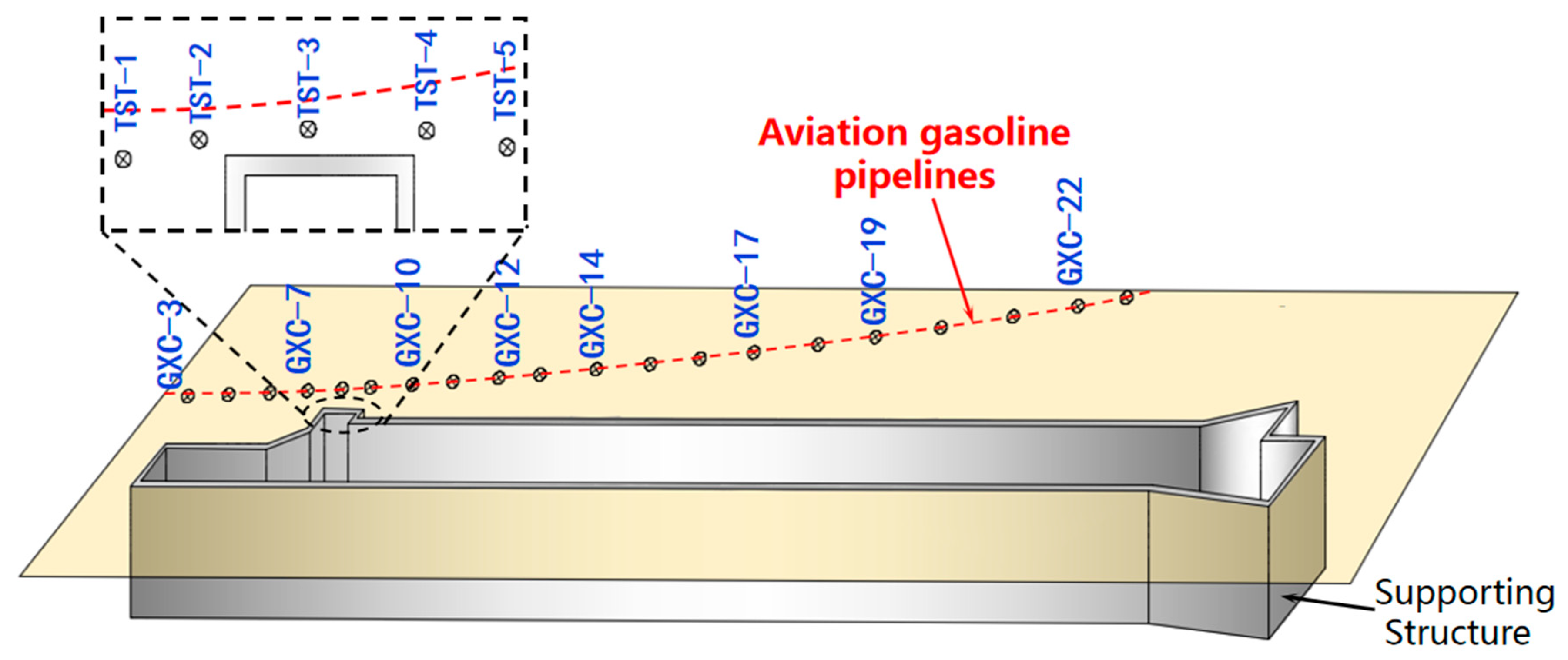
4.1. Test Scheme
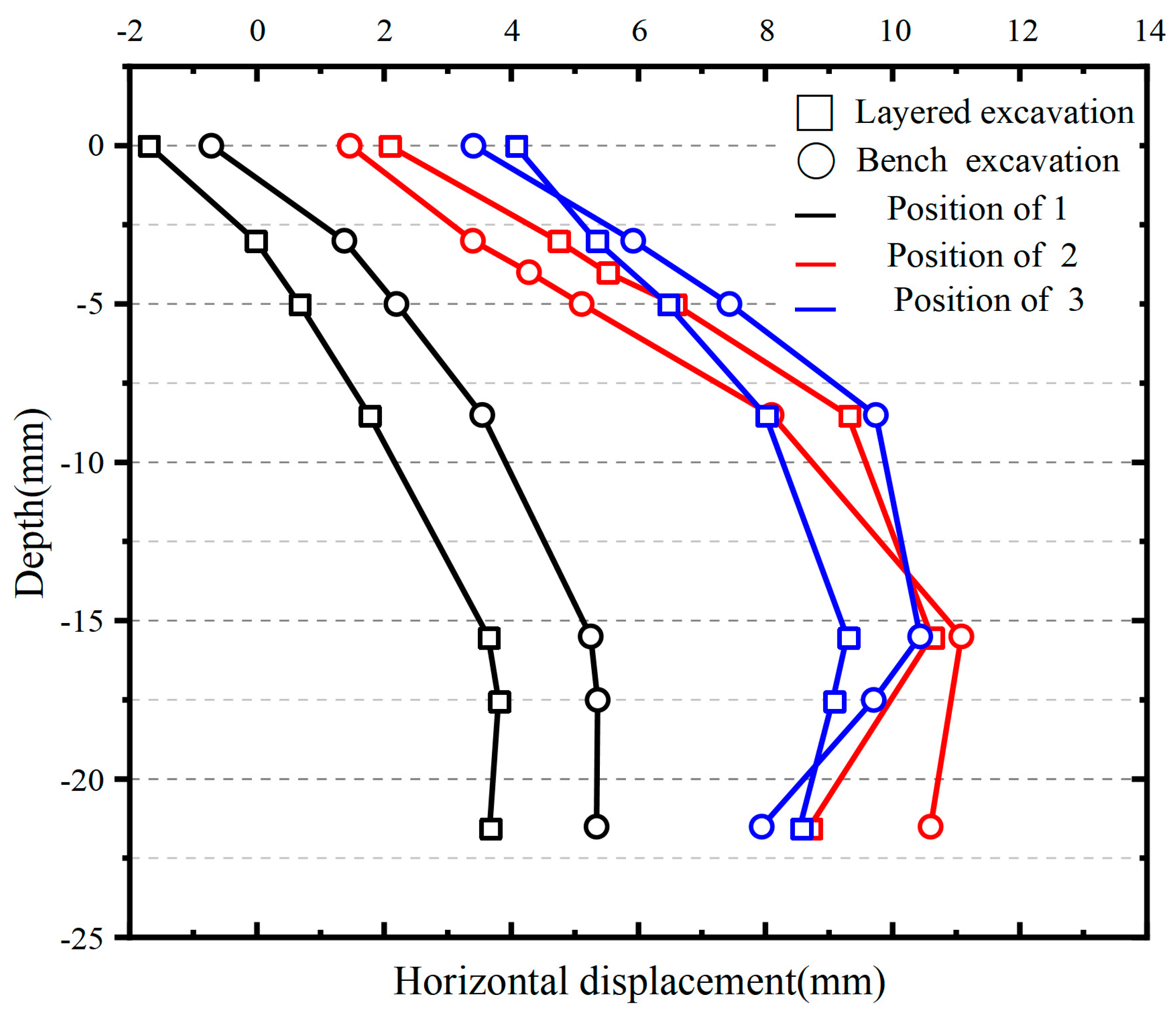
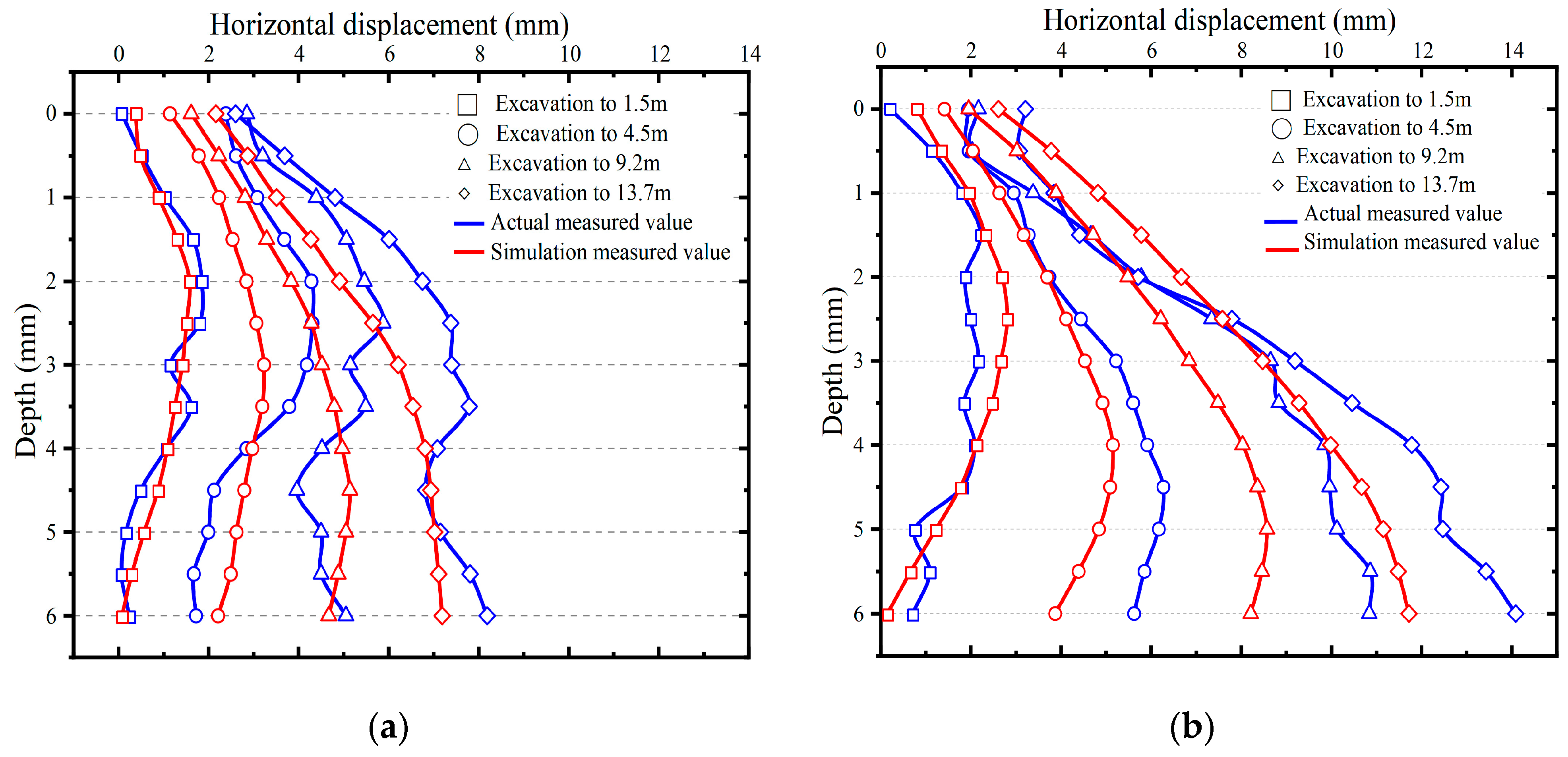
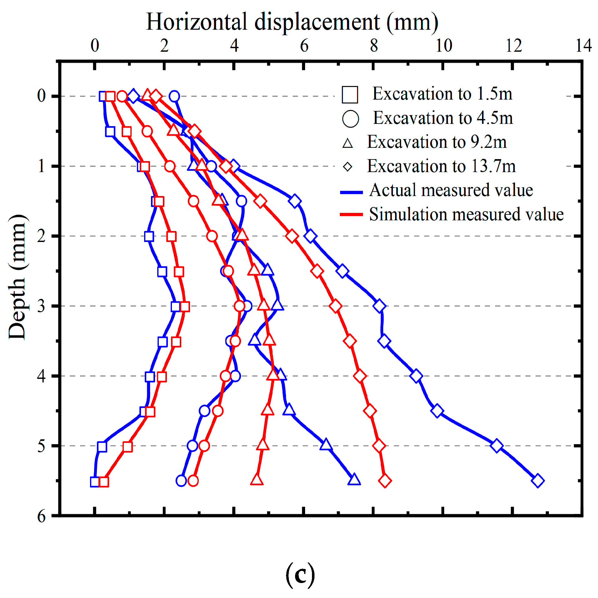
4.2. Horizontal Displacement of Soil Adjacent to Pipeline
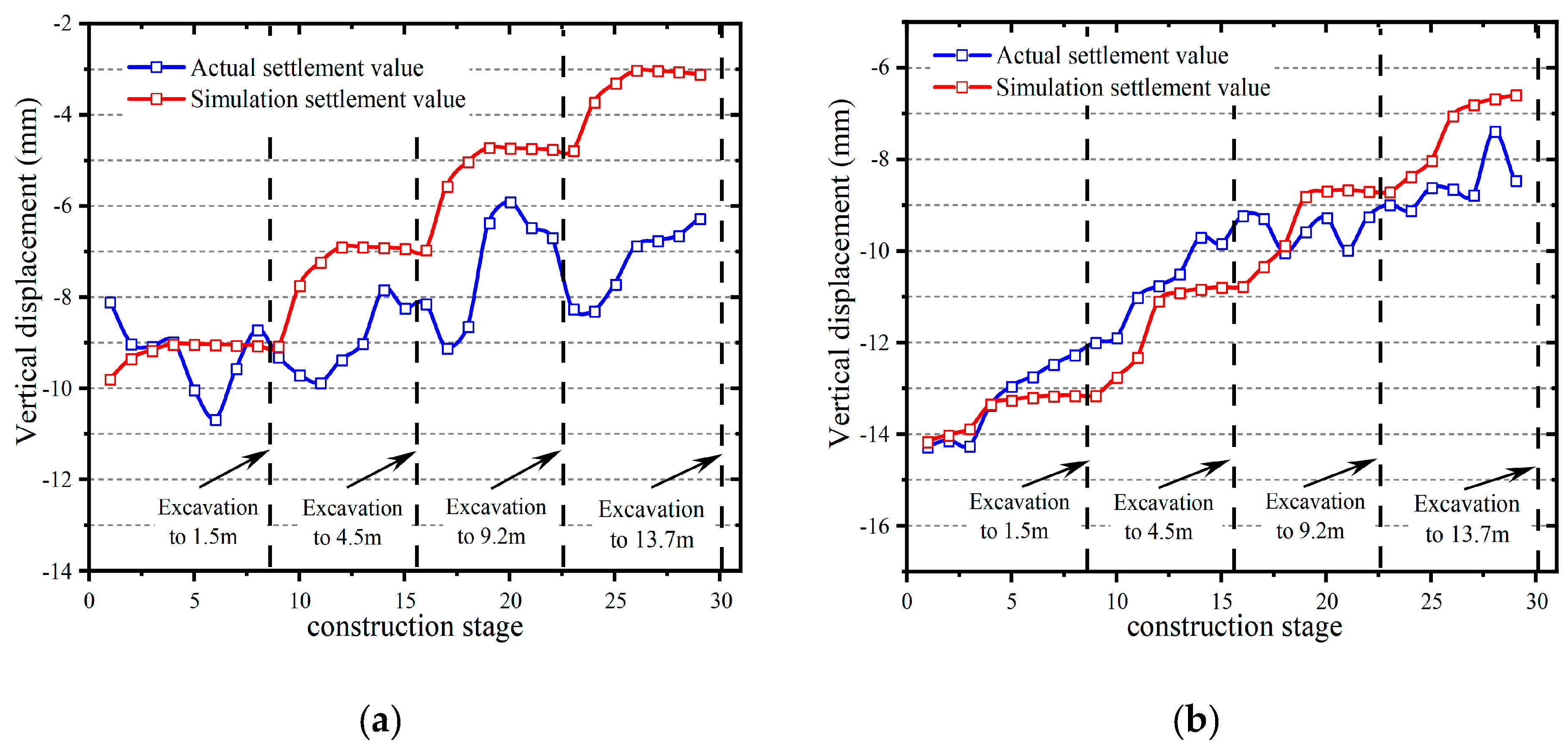
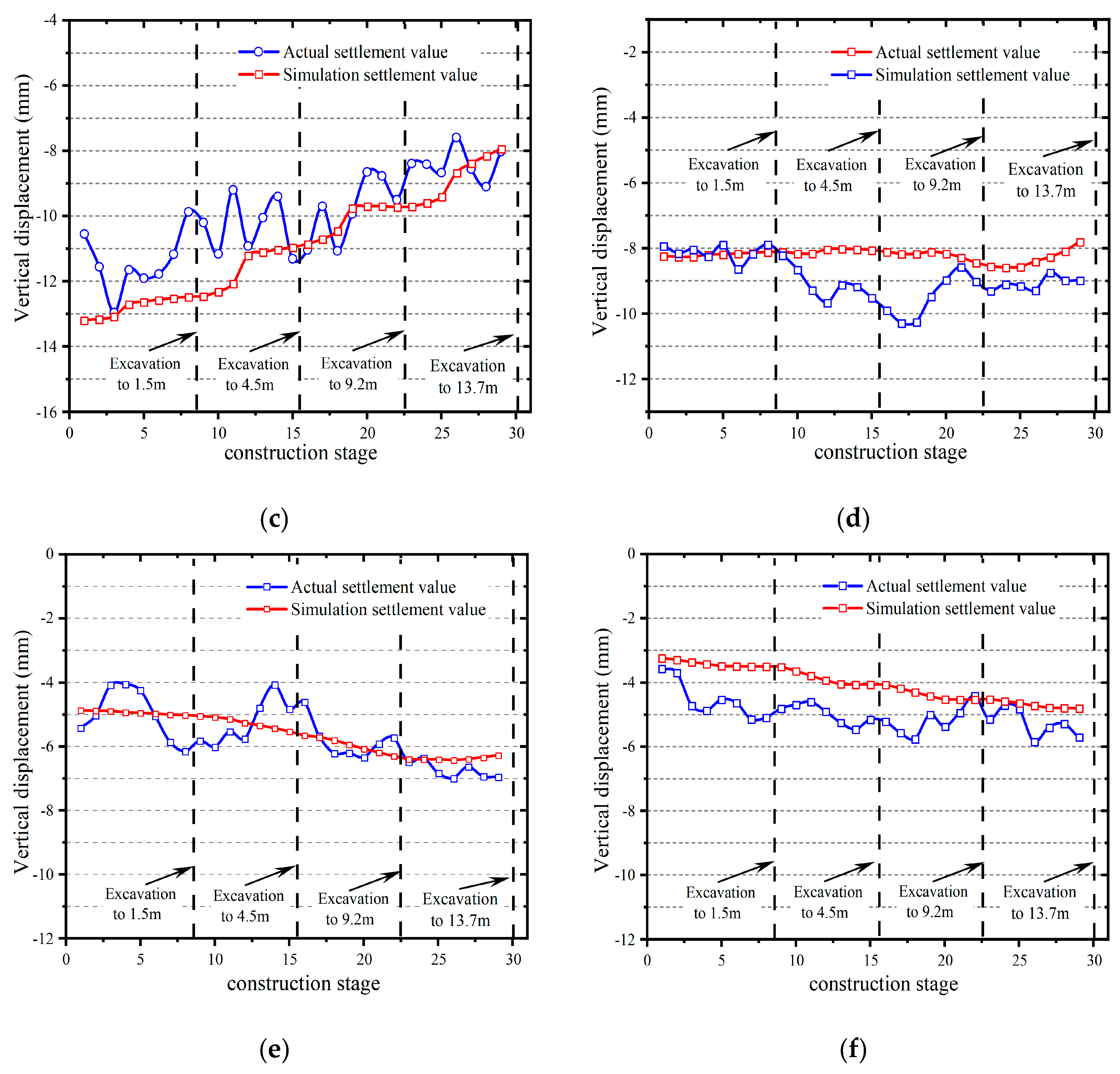
4.3. Soil Settlement at the Top of Pipeline
5. Discussions
6. Conclusions
Author Contributions
Funding
Institutional Review Board Statement
Informed Consent Statement
Data Availability Statement
Conflicts of Interest
References
- Zhang, Y.W.; Weng, X.L.; Song, Z.P.; Sun, Y.F. Modeling of Loess Soaking Induced Impacts on a Metro Tunnel Using a Water Soaking System in Centrifuge. Geofluids 2019, 2019, 5487952. [Google Scholar] [CrossRef]
- Cheng, W.C.; Song, Z.P.; Tian, W.; Wang, Z.F. Shield tunnel uplift and deformation characterisation: A case study from Zhengzhou metro. Tunn. Undergr. Space Technol. 2018, 79, 83–95. [Google Scholar] [CrossRef]
- Peck, R.B. Deep excavations and tunneling in soft ground. In Proceedings of the 7th International Conference on Soil Mechanics and Foundation Engineering, State of the Art Volume, Mexico City, Mexico, August 1969; pp. 225–290. [Google Scholar]
- Crofts, J.E.; Menzies, B.K.; Tarzi, A.I. Lateral displacement of shallow buried pipelines due to adjacent deep trench excavations. Geotechnique 1977, 27, 161–179. [Google Scholar] [CrossRef]
- Li, D.Y.; Zhang, T.Q.; Gong, X.N. Analysis of the displacements of buried pipelines caused by deep excavations. Indus. Constr. 1999, 29, 36–42. (In Chinese) [Google Scholar]
- Klar, A.; Marshall, A.M. Shell versus beam representation of pipes in the evaluation of tunneling effects on pipelines. Tunn. Undergr. Space Technol. 2007, 23, 431–437. [Google Scholar] [CrossRef]
- Zhang, C.; Yu, J.; Huang, M. Effects of tunnelling on existing pipelines in layered soils. Comput. Geotech. 2012, 43, 12–25. [Google Scholar] [CrossRef]
- Jiang, Z. Theoretical analysis on deformation of pipeline caused by adjacent foundation pit excavation. Chin. J. Undergr. Space Eng. 2014, 10, 362–368. (In Chinese) [Google Scholar]
- Zhang, Z.; Zhang, M.; Zhao, Q. A simplified analysis for deformation behavior of buried pipelines considering disturbance effects of underground excavation in soft clays. Arab. J. Geosci. 2015, 8, 7771–7785. [Google Scholar] [CrossRef]
- Tan, Y.; Lu, Y. Responses of shallowly buried pipelines to adjacent deep excava-tions in Shanghai soft ground. J. Pipeline Syst. Eng. Pract. 2018, 9, 05018002. [Google Scholar] [CrossRef]
- Liu, N.W.; Chen, Y.T. Analysis of deformation characteristics of foundation pit of metro station and adjacent buildings induced by deep excavation in soft soil. Rock Soil Mech. 2019, 40, 1515–1525. [Google Scholar] [CrossRef]
- Tan, Y.; Huang, R.; Kang, Z.; Bin, W. Covered Semi-Top-Down Excavation of Subway Station Surrounded by Closely Spaced Buildings in Downtown Shanghai: Building Response. J. Perform. Constr. Facil. 2016, 30, 04016040. [Google Scholar] [CrossRef]
- Leung, E.H.Y.; Ng, C.W.W. Wall and Ground Movements Associated with Deep Excavations Supported by Cast In Situ Wall in Mixed Ground Conditions. J. Geotech. Geoenvironmental. Eng. 2007, 133, 129–143. [Google Scholar] [CrossRef]
- Finno, R.J.; Bryson, L.S. Response of Building Adjacent to Stiff Excavation Support System in Soft Clay. J. Perform. Constr. Facil. 2002, 16, 10–20. [Google Scholar] [CrossRef]
- Sharma, J.; Hefny, A.; Zhao, J.; Chan, C. Effect of large excavation on deformation of adjacent MRT tunnels. Tunn. Undergr. Space Technol. 2001, 16, 93–98. [Google Scholar] [CrossRef]
- Dinakar, K.N.; Prasad, K.S. Effect of deep excavation on adjacent buildings by diaphragm wall technique using PLAXIS. IOSR-J. Mech. Civil Eng. 2014, 3, 26–32. [Google Scholar]
- Miliziano, S.; Caponi, S.; Carlaccini, D.; de Lillis, A. Prediction of tunnelling-induced effects on a historic building in Rome. Tunn. Undergr. Space Technol. 2021, 119, 104212. [Google Scholar] [CrossRef]
- Doležalová, M. Tunnel complex unloaded by a deep excavation. Comput. Geotech. 2001, 28, 469–493. [Google Scholar] [CrossRef]
- Yang, X.; Song, H.W.; Qin, Y.M. Numerical analysis for influence of deep excavation on adjacent unprotected under-ground pipelines. J. Water Resour. Archit. Eng. 2011, 9, 19–24. (In Chinese) [Google Scholar]
- Shi, J.; Wang, Y.; Ng, C.W. Buried pipeline responses to ground displacements induced by adjacent static pipe bursting. Can. Geotech. J. 2013, 50, 481–492. [Google Scholar] [CrossRef]
- Al-Khazaali, M.; Vanapalli, S.K.; Oh, W.T. Numerical investigation of soil–pipeline system behavior nearby unsupported excavation in saturated and unsaturated glacial till. Can. Geotech. J. 2018, 56, 69–88. [Google Scholar] [CrossRef]
- Sun, Q.; Yan, C.; Qiu, J.; Xu, B.; Xu, B.; Sha, J. Numerical Simulation of a Deep Excavation near a Shield Tunnel. Teh. Vjesn. 2018, 25, 670–678. [Google Scholar] [CrossRef]
- Zhang, J.; Xie, R.; Zhang, H. Mechanical response analysis of the buried pipeline due to adjacent foundation pit excavation. Tunn. Undergr. Space Technol. 2018, 78, 135–145. [Google Scholar] [CrossRef]
- Ye, S.H.; Zhao, Z.F.; Wang, D.Q. Deformation analysis and safety assessment of existing metro tunnels affected by excavation of a foundation pit. J. Undergound Space. 2021, 6, 421–431. [Google Scholar] [CrossRef]
- Liu, H.; Li, P.; Liu, J. Numerical investigation of underlying tunnel heave during a new tunnel construction. Tunn. Undergr. Space Technol. 2011, 26, 276–283. [Google Scholar] [CrossRef]
- Ng, C.W.; Shi, J.; Hong, Y. Three-dimensional centrifuge modelling of basement excavation effects on an existing tunnel in dry sand. Can. Geotech. J. 2013, 50, 874–888. [Google Scholar] [CrossRef]
- Wang, J.; Huo, Q.; Song, Z.; Zhang, Y. Study on adaptability of primary support arch cover method for large-span embedded tunnels in the upper-soft lower-hard stratum. Adv. Mech. Eng. 2019, 11, 1687814018825375. [Google Scholar] [CrossRef]
- Li, D.P.; Tang, D.G.; Yan, F.G. Mechanics of deep excavations spatial effect and soil pressure calculation method considering its influence. J. Zhejiang. Univ. Eng. Sci. 2014, 48, 1632–1639. (In Chinese) [Google Scholar]
- Hsieh, P.G.; Ou, C.Y. Shape of ground surface settlement profiles caused by excavation. Can. Geotech. J. 1998, 35, 1004–1017. [Google Scholar] [CrossRef]


| Soil Layer | Average Thickness (m) | γ (kN/m3) | φ (°) | c (kPa) | ω (%) | Void Ratio e | E (MPa) | |
|---|---|---|---|---|---|---|---|---|
| Clay | 2.1 | 18.1 | 8.5 | 19.4 | 0.3 | 42.1 | 1.241 | 12 |
| Muddy clay | 3.5 | 17.5 | 6.7 | 7.6 | 0.35 | 45.1 | 1.309 | 8.5 |
| Silty clay | 7.0 | 19.0 | 12.9 | 12 | 0.35 | 30.4 | 0.873 | 15 |
| Clay | 1.9 | 18.0 | 9 | 14.1 | 0.33 | 29.2 | 0.862 | 15 |
| Silty clay | 1.7 | 20.1 | 12.3 | 14.2 | 0.35 | 23.1 | 0.673 | 17 |
| Silty clay | 1.9 | 20.4 | 12.1 | 13.8 | 0.35 | 22.3 | 0.674 | 16 |
| Sandy silt | 4.7 | 20.1 | 29.9 | 15.9 | 0.3 | 21.7 | 0.642 | 23 |
| Silty clay | 5.9 | 19.2 | 10.8 | 24.6 | 0.32 | 28.8 | 0.835 | 20 |
| Silty clay | 3.0 | 19.8 | 13 | 15 | 0.34 | 23.2 | 0.694 | 22 |
| Sandy silt | 1.6 | 20.3 | 29 | 14 | 0.31 | 19.7 | 0.607 | 28 |
| Material | Element Type | Constitutive Relation | E (GPa) | γ (kN/m3) | |
|---|---|---|---|---|---|
| Waterproof curtain | Plate element | Elasticity | 0.015 | 0.20 | 21.5 |
| Bored pile | Plate element | Elasticity | 31.5 | 0.20 | 25 |
| DN200 pipe | Plate element | Elasticity | 210 | 0.30 | 78.5 |
| Concrete support | Beam element | Linear elasticity | 31.5 | 0.20 | 25 |
| Steel support | Beam element | Linear elasticity | 210 | 0.30 | 78.5 |
| No. | Soil Texture | Mass (kN/m3) | Angle of Internal Friction (°) | Cohesion (kPa) | Elastic Modulus (MPa) | Poisson’s Ratio |
|---|---|---|---|---|---|---|
| Soil layer 1 | Plain fill | 18.1 | 8.5 | 19.4 | 6.0 | 0.2 |
| Soil layer 2 | Clay | 18.1 | 8.5 | 19.4 | 12.0 | 0.2 |
| Soil layer 3 | Silty clay | 18.1 | 8.5 | 19.4 | 12.0 | 0.35 |
| Construction Method | Name of Soil Property | Plain Fill | Clay | Silty Clay |
|---|---|---|---|---|
| Layered excavation | Max. (mm) | 6.62 | 7.16 | 8.97 |
| Min. (mm) | 3.34 | 3.19 | 2.21 | |
| Avg. (mm) | 5.37 | 5.53 | 6.14 | |
| Bench excavation | Max. (mm) | 8.81 | 9.87 | 12.46 |
| Min. (mm) | 4.07 | 3.51 | 3.36 | |
| Avg. (mm) | 6.73 | 7.05 | 8.23 |
Disclaimer/Publisher’s Note: The statements, opinions and data contained in all publications are solely those of the individual author(s) and contributor(s) and not of MDPI and/or the editor(s). MDPI and/or the editor(s) disclaim responsibility for any injury to people or property resulting from any ideas, methods, instructions or products referred to in the content. |
© 2023 by the authors. Licensee MDPI, Basel, Switzerland. This article is an open access article distributed under the terms and conditions of the Creative Commons Attribution (CC BY) license (https://creativecommons.org/licenses/by/4.0/).
Share and Cite
Song, Z.; Wu, Y.; Zhang, Y.; Wang, K.; Tian, J.; Tian, X. Deformation Response of a Pipeline to Nearby Deep Foundation Pit Excavation: Numerical Simulations and Field Tests. Appl. Sci. 2023, 13, 6597. https://doi.org/10.3390/app13116597
Song Z, Wu Y, Zhang Y, Wang K, Tian J, Tian X. Deformation Response of a Pipeline to Nearby Deep Foundation Pit Excavation: Numerical Simulations and Field Tests. Applied Sciences. 2023; 13(11):6597. https://doi.org/10.3390/app13116597
Chicago/Turabian StyleSong, Zhanping, Youchuan Wu, Yuwei Zhang, Kuisheng Wang, Jiale Tian, and Xiaoxu Tian. 2023. "Deformation Response of a Pipeline to Nearby Deep Foundation Pit Excavation: Numerical Simulations and Field Tests" Applied Sciences 13, no. 11: 6597. https://doi.org/10.3390/app13116597