Abstract
The physical and mechanical properties of the reservoir bank slope deteriorate under the fluctuation of water level, causing bank debonding and slippage, which can produce different degrees of damage to the bridge foundation, piers, and superstructure, a condition that is difficult to treat. In this paper, for a Yangtze River Bridge bank slope instability problem in the Three Gorges reservoir area, a numerical model of the bank slope and bridge was established using the finite element-SPH conversion coupling algorithm, and the pile pier damage development law and damage mode (deformation and stress–strain curves of the bank slope and pile foundation) were obtained according to the geological conditions of the bridge location. Additionally, combined with the characteristics of bank destabilization in the reservoir area of the Three Gorges Yangtze River Bridge, landslide management is proposed by using soil drainage and anti-slip pile reinforcement measures. In addition, for the characteristics of bridge pier deflection, a comprehensive deflection correction reinforcement method of pushing deflection correction, adding pile foundation, expanding pile bearing, and increasing pier cross-sectional area is proposed, so as to provide a theoretical basis for the prevention and control of reservoir bank landslides, the service life of pile structure, and the disposal of diseases.
1. Introduction
With the completion of the reservoir area and water storage, the reservoir water level periodically rises and falls, resulting in the deterioration and geotechnical damage of the reservoir bank slope subsidence zone, which has a significant impact on the stability of the bank slope [1,2,3,4,5]. The bank slope deformation and slip accumulation on the reservoir bank bridge pile foundation have a long-term lateral extrusion effect, causing the occurrence of bridge foundation, pier, and bridge span structure damage and threatening the adjacent existing bridge structure’s safety and stability [6], such as pier cracking of the bridge foundation. Pier and span structures are subject to structural damage, such as pier cracking, pier tilting, and girder misalignment. Therefore, it is necessary to investigate the long-term effects of deformation and slip accumulation on the reservoir bank bridge structure under the cycle of reservoir water level rise and fall.
For the problem with the periodic rise and fall of the water level in the reservoir area, many scholars have found that the stability of the reservoir bank slope is predominantly affected by the cycle of reservoir water level rise and fall. Miao et al. [7], Kafle et al. [8], and Xue et al. [9] analyzed the stability of the reservoir bank slope zone based on the centrifugal slope model, rock strength deterioration mode, geological survey analysis, dry and wet cycle tests, numerical simulation, etc., and all noted that with the increase in the reservoir water level rise and fall cycle, the geotechnical equilibrium gradually deteriorated. With the increase in the number of cycles of reservoir water level rise and fall, the balance of rock and soil bodies gradually deteriorated, leading to the instability of the reservoir bank slope. In recent years, with the cycle of water level rise and fall in the reservoir area, landslide disasters have occurred in the reservoir area, and bank slope control has become the focus of research. Scholars have studied the overall stability of bridge bank slopes based on numerical simulation by combining the geological conditions and environmental factors of bridge banks and provided corresponding suggestions for the design and prevention of pile foundations and piers of reservoir bank bridges [10]. Liu et al. [11] studied the prevention and control effect of anti-slip piles under the fluctuation of reservoir water level by centrifuge model test and noted that the prevention and control effect of landslides was evident when the soil arch effect was generated between piles and soil. However, the above studies only focused on the deformation and stability of the bank slope and disregarded the effects of slope deformation and slip on the adjacent structures of the reservoir bank.
These studies showed that the pile transverse bearing capacity and reliability analysis were mainly based on the pile transverse displacement as the criterion [12,13]. In this regard, many scholars have conducted a series of studies on the pile displacement of the coupled pile-soil system of slopes under changes in the reservoir water level. Diao et al. [14] obtained the trend of landslide-pile deformation under the infiltration effect when the reservoir water level fluctuated via numerical simulation based on an actual project. Sawant et al. [15] further investigated the influence of the pro-slope distance and slope ratio on the pile force deformation characteristics by numerical simulation and found that the pile top displacement and pile bending moment were proportional to the slope ratio. Xing et al. [16] analyzed the pile displacement deformation under the reservoir water level cycle based on the stiffness decay model and soil strength degradation model in conjunction with engineering practice and noted that the cumulative pile displacement continuously increased with the number of water level cycles. Liu [17] established a bank slope-bridge pile interaction model under the condition of rising reservoir water levels and found that with the rising water level, the continuous deformation of the soil around the pile generated a transverse shear force on the pile foundation, and the pile displacement continuously increased. Zhou [18] analyzed the influence of different degrees of bank slope deformation on the bridge substructure by finite element with engineering examples and noted that bank slope deformation and sliding were the main reasons for the deflection of the bridge pier. In summary, both the test and the actual engineering cases showed that once the deformation and sliding of the bank slope started to occur, it had a highly adverse effect on the bridge pile foundation; however, few studies have considered the long-term effect of the continuous deformation and sliding of the bank slope on the bridge pile foundation caused by the cycle of reservoir water level rise and fall, and the long-term interaction mechanism and failure mode of the bank slope-bridge pile foundation are not yet clear; thus, this problem needs to be further studied in depth.
To address the above problems, this paper uses a finite element method-smoothed particle hydrodynamics (FEM-SPH) conversion coupling algorithm to establish a three-dimensional model of a bank slope-bridge pile foundation, considering the deterioration effect of bank slope soil engineering properties under the action of the reservoir water level cycle. The entire process of bank slope deformation, slip, and destabilization under changing water levels is simulated; the mechanism of interaction between bank slope slip and bridge pile foundation is shown; and the deflection trend of the bridge pier and failure mode of the substructure are examined. According to the damage development trend, the damage mode of the pile foundation piers, and the characteristics of the Three Gorges Reservoir area, reinforcement measures and a comprehensive deflection correction reinforcement method are proposed.
2. FEM-SPH Conversion Coupling Algorithm
2.1. FEM-SPH Coupling Algorithm
The bank slope will gradually change from small deformation to large deformation from the initial stable state to the sliding destabilization of the soil after landslide formation. The Lagrange finite element method (FEM) can effectively deal with the small deformation case, but there is a mesh distortion problem for the large deformation case. The smooth particle hydrodynamics (SPH) method can avoid mesh distortion and better simulate the behavior of splash and damage, but its computational efficiency is low and boundary constraints are difficult [19,20]. Additionally, the coupled FEM-SPH algorithm can combine the strengths of both and deal with large deformation problems efficiently and accurately.
The general FEM-SPH coupling algorithm will start the analysis with larger deformations in regions that will likely be discretized as SPH particles, while other regions are still analyzed using FEM. Since this method requires some locations to be defined as SPH particles before the analysis, it was necessary to accurately predict the areas where large deformation is likely to occur. In this paper, it involves the whole process of the shore slope, from the initial stable state to the final deformation and destabilization. The range, shape, and location of the sliding zone are unknown, and it is difficult to determine which areas of the finite element mesh will be deformed. If the whole shore slope is discretized into SPH particles at the beginning, it will lead to low computational efficiency.
In this paper, the FEM-SPH conversion coupling algorithm could effectively solve the above problem. In the initial stage of analysis, the whole bank slope was a finite element mesh, and the soil slides after the sliding surface is formed. When the sliding zone finite element mesh was excessively distorted, it was converted into SPH particles so as to realize the simulation of the whole process from deformation and sliding to destabilization damage of the bank slope.
2.2. FEM-SPH Conversion Principle
The FEM-SPH conversion algorithm was based on equal effect variation; that is, specifically, when the finite element mesh reached the set equal effect variation threshold, it replaced the Lagrange finite element mesh in the form of the SPH integral to participate in the subsequent calculation [21]. The FEM-SPH conversion process is shown in Figure 1. The whole object was initially a finite element mesh. During the analysis process, some meshes were excessively distorted and converted into SPH particles. C and D elements associated with node N1 reached the equivalent strain conversion threshold, met the conversion conditions, and the element failed; however, A and B elements did not meet the conditions, and the element did not fail. Class I SPH particles were generated at the interface node between the failed element and the non-failed element, and these particles were fixed at the interface node. The units associated with node N2 failed, and class II SPH particles were generated at this node, which could move freely.
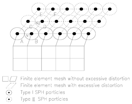
Figure 1.
Conversion of FEM to a SPH particle.
After the conversion of FEM to SPH particles, the newborn SPH particles will inherit the physical quantities of the failed nodes and participate in the subsequent calculations, and the assignment process is as follows:
where, x, m, ρ, V, v and σ are the position, mass, density, volume, velocity, and stress tensor, respectively. Subscripts p denote SPH particles, subscripts n denote finite element nodes, subscripts e denote finite cells, and subscripts g denote Gaussian integration points within the finite element. Ne is the number of finite cells associated with a node; Nn is the number of individual finite cell nodes. σei is the unit stress tensor. σgj and ωgj is the stress tensor and weighting factor at the Gaussian integration point g inside the unit i. Ng is the number of Gaussian integration points within a single finite element.
Since the concept of SPH smooth length does not exist in Lagrange finite elements, the newly generated SPH particles cannot be directly inherited from the finite element nodes, instead, they must be calculated using the law of mass conservation:
where, ρ0 and ρ are the initial and current densities, respectively. r0 is the initial cell size. a is the smooth length to cell size ratio factor. d is the dimensionality.
3. Finite Element Model of Bank Slope-Bridge Pile Foundation Interaction under Reservoir Water Level Cycling Conditions
3.1. Bridge Project Background
The Yangtze River Bridge was built in 2003; with four two-way lanes. It belongs to the main urban expressway. The upper structure of the approach bridge on the north bank of the bridge uses a 7 × 40 m prestressed simply supported T-beam, with 10 beams arranged in the transverse direction of the bridge; the substructure was a double column pier and pile foundation; the 1#~4# pier diameter is 2.5 m, the 5#~6# pier diameter is 2.8 m, the pile pier transverse spacing is 11.4 m, and C30 concrete was used. The overall slope of the bank slope at the bridge site was approximately 10~15°, which was a rock-soil mixed slope. The terrain of the approach bridge is shown in Figure 2.
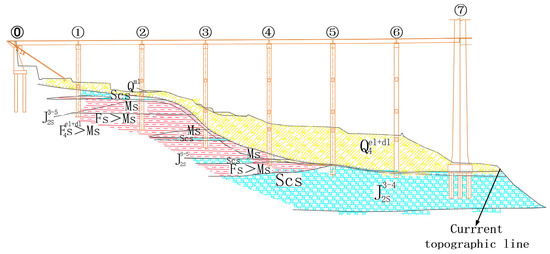
Figure 2.
Topography of the north bank approach of a Yangtze River Bridge.
Since the completion of the bridge, the slope has experienced 14 cycles of water level rise and fall (N = 14), and the shear strength parameters of the covering soil layer have been greatly reduced and the physical and mechanical properties have been seriously degraded, which leads to deformation and slippage of the soil body. Some piers of the approach bridge on the north bank are inclined and offset towards the river center, of which the 6# pier offset was the most significant. The maximum offset of the pier top to the river center was 0.63 m. There was an obvious gap between the pile foundation and the soil. The deviation is shown in Figure 3.
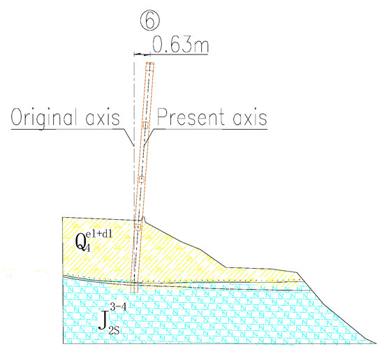
Figure 3.
Inclination and deviation of the pile pier.
3.2. Three-Dimensional Bank-Bridge Finite Element Model
3.2.1. Structural Dimensions and Boundary Loads
ABAQUS software was used to establish the three-dimensional shore slope-pile pier model of pier 6#, and the boundary range was 90 m long (longitudinal bridge direction) and 30 m wide; the total length of the pile pier is 81.5 m; the depth of the pile foundation embedded in the overburden of the bank slope was 22.86 m; and the depth of embedded bedrock was 3.5 m. In this paper, we focused on the influence of the shore slope deformation on the pile pier, so the reinforcement mainly considers the pile pier stirrup with a diameter of 12 mm and the pile pier longitudinal reinforcement with a diameter of 25 mm. The arrangement of crossbeams and cover beams is not considered.
Due to the fact that the FEM-SPH algorithm may have SPH particles flying around, there will be problems with using normal or fixed constraints, so four fixed rigid boundary retaining walls were set around the bank slope with the purpose of imposing normal constraints around it. The bottom of the bank slope and rock layers were fixed with three-way restraints; the bank slope was set with a smooth contact with the inner side of the retaining wall; the rest of the contact’s normal behavior is expressed by a “hard contact”, and the tangential behavior is expressed by a “penalty friction”. The steel reinforcement is embedded in the concrete pile pier. The top of the pier was subjected to 1345 t of vertical load, which was equivalent to the surface load applied to the cover beam. The three-dimensional shore-slope-pier structure model is shown in Figure 4.
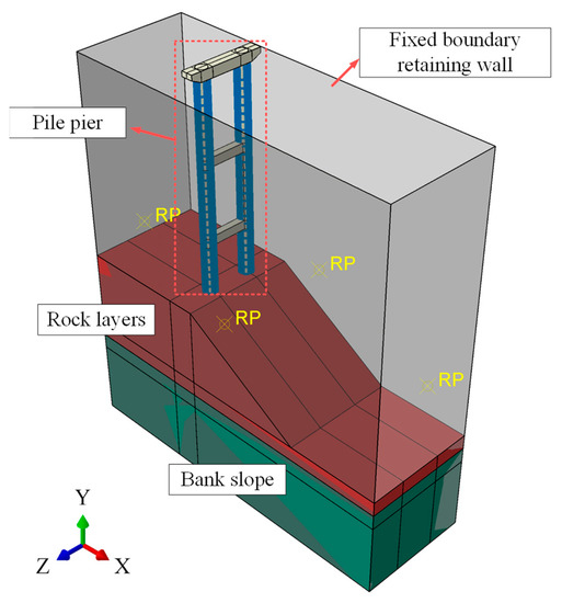
Figure 4.
Three-dimensional bank slope-bridge pier model.
3.2.2. Element and Grid Division
The bank slope soil body was simulated by a FEM-SPH conversion algorithm, and a C3D8R element was used before conversion to SPH particles; the geotechnical body and concrete are simulated by a C3D8R element; the reinforcement of the pile pier was simulated by a T3D2 element. The number of pile pier units was 96,181, the number of reinforcement units was 22,424, the number of geotechnical units of the shore slope was 82,324, and the grid division of the shore slope-pile pier structure model is shown in Figure 5.

Figure 5.
Division of the three-dimensional numerical model mesh.
3.2.3. Constitutive Parameter
The elastic-plastic damage model was adopted for the concrete constitutive model, and its uniaxial stress-strain relationship is input using the calculation method in Appendix C of the Code for the Design of Concrete Structures (GB50010-2010) [22]; the elastic-plastic strengthening constitutive model was used for the steel reinforcement, with an elastic modulus of 200 GPa, a Poisson’s ratio of 0.3, a yield strength of 335 MPa, and a strength limit of 460 MPa.
The Mohr–Coulomb constitutive model was adopted for sandstone, with an elastic modulus of 6300 MPa, a Poisson’s ratio of 0.25, a density of 2500 kg/m3, a cohesion of 2700 kPa, and an internal friction angle of 42°. The Mohr–Coulomb constitutive model was adopted for the soil, with a density of 2100 kg/m3 and a Poisson’s ratio of 0.35. Its elastic modulus, cohesion, and internal friction angle were affected by the rise and fall cycle of the reservoir water level. In this paper, we consider the strength-discounting effect on the soil caused by one cycle of water level rise and fall, and we mainly realize the simulation of the dry and wet cycle effects on the soil by discounting and degrading the key parameters of the soil (including internal friction angle, elastic modulus, and cohesion) through field variables. This paper combines the geological survey data of the shore slope in the bridge site area [18], and based on the deterioration law of soil parameters proposed by Tu [23], which is highly correlated with this case, the expression of the deterioration curve is as follows:
where pσ is the surrounding pressure and its value is 15 kpa, Et(m) is the modulus of elasticity of the geotechnical body after m cycles of water level in the reservoir area, Et(0) is the initial modulus of elasticity of the geotechnical body, c(m) is the cohesive force of the geotechnical body after m cycles of water level in the reservoir area, c(0) is the initial cohesive force of the geotechnical body; φ(m) is the friction angle within the geotechnical body after m cycles of water level in the reservoir area, and φ(0) is the initial internal friction angle of the geotechnical body.
The values of soil strength parameters of the bank slope under different times of reservoir water level rise and fall cycles were obtained by regression calculations for 0~20 reservoir water level rise and fall cycles. The deterioration law of the soil strength parameter is shown in Figure 6. By defining the field variables, the soil strength parameters were impaired with the increase in analysis time according to the curve in Figure 6 to simulate the degradation effect of soil strength parameters under the action of reservoir water level cycles.
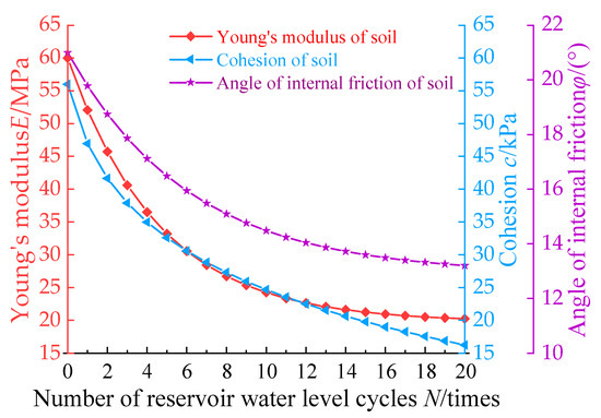
Figure 6.
Deterioration law of soil strength parameters.
4. Analysis of Damage Mechanisms Caused by Bank Slope-Bridge Pile Foundation Interaction under the Condition of Reservoir Water Level Circulation
4.1. Bank Slope Stability Analysis
To evaluate the stability of the bank slope under the action of the reservoir water level cycle, the appropriate criterion should be selected to judge whether the bank slope is unstable or not. For the slope instability problem, the traditional criteria include a sudden change in displacement of characteristic points, non-convergence of numerical calculations, and plastic zone penetration. In the case of an unknown sliding zone, Zhou et al. [24] pointed out that it was more reasonable to use the sudden change in displacement increment at the top and bottom of the landslide as the criterion of landslide instability. Therefore, in this paper, the midpoint of the top and bottom of the bank slope was used as the characteristic point to record its displacement. From the sudden change in the displacement curve of the characteristic points at the top and bottom of the bank slope, the inflection point was the critical point of the bank slope instability. The displacement of the characteristic point of the bank slope is shown in Figure 7.
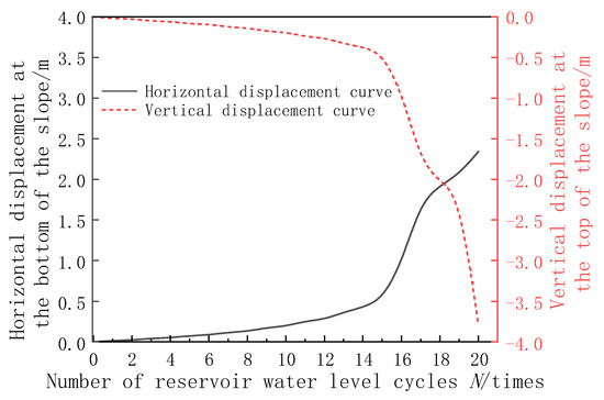
Figure 7.
Displacement of characteristic points.
As can be seen from Figure 7, the displacement of the characteristic point of the bank slope under the characteristic points of the reservoir level cycle and the displacement increment gradually increased in the first 15 cycles of reservoir level rise and fall; therefore, the action of the reservoir level cycle will accelerate the deformation of the bank slope. In the 16th water level rise and fall cycle, the displacement of the two characteristic points had a cliff-like mutation and an evident inflection point appeared; thus, the bank slope was unstable and became damaged during the 16th water level rise and fall cycle. After the 16th water level rise and fall cycle, the sliding zone soil body separates from the original slope and slides to a new stable state. The displacement increments gradually decreased, and the displacement gradually tended to be stable. In the 20th water level rise and fall cycle, the increment of displacement at the bottom of the slope did not change much, but the increment of displacement at the top of the slope abruptly changed again, so it was presumed that the second destabilization of the slope may have occurred.
In order to confirm the above speculation, the finite element mesh of the sliding zone of the bank slope appeared to be excessively distorted and transformed into SPH particles. As a criterion, it was believed that when the finite element mesh of the sliding zone of the bank slope was completely transformed into SPH particles, the soil on the sliding zone would detach and slide down, and destabilization damage would occur. The deformation of the bank slope-bridge pier is shown in Figure 8.
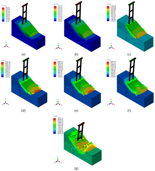
Figure 8.
Deformation nephograms of bank slope-bridge pier: (a) 14 times, (b) 15 times, (c) 16 times, (d) 17 times, (e) 18 times, (f) 19 times, and (g) 20 times. (Unit: mm).
As can be seen from Figure 8, the finite element mesh of the shore slope was not transformed into SPH particles in the first 15 water level cycles, and the shore slope was not destabilized. When N = 16, the finite element mesh of the sliding zone of the shore slope has been transformed into SPH particles, so in the 16th water level lift cycle, the shore slope will be destabilized and damaged. After the shore slope is destabilized, the soil in the sliding zone slides downward and reaches a new equilibrium state. In the 17th to 19th water level lift cycles, the equilibrium state was basically unchanged, but the soil arch effect on the back side of the pile became more and more obvious, indicating that the soil thrust on the back side of the pile gradually increased and the pile foundation played a blocking role in the slippage of the bank slope deformation instability. When N = 20, a new sliding zone was formed in the soil behind the pile, and a large number of finite element meshes were transformed into SPH particles. Therefore, it could be determined that the bank slope will be destabilized during the 20th water level lifting cycle, which verifies the speculation in the previous paper.
In summary, the first slope instability will occur in the 16th water level rise and fall cycle. In the 17th to 19th water level rise and fall cycles, the slope was temporarily in a new stable state due to the blocking effect of the pile foundation on the sliding of the slope due to deformation and instability. However, the unbalanced soil thrust on the pile foundation gradually increased. In the 20th water level lift cycle, the second instability damage to the bank slope occurs. The FEM-SPH conversion coupling algorithm can simulate the 10 in view 19 times more intuitively and accurately by completely converting the finite element mesh of the slip zone into SPH particles as the bank slope instability criterion and analyzing the whole process of deformation, sliding, and instability of the bank slope.
4.2. Analysis of Pier Deformation Characteristics
4.2.1. Comparison between Numerical Simulation and Engineering Measurement
The shore slope of pier 6# experienced 14 water level lifting cycles, and the displacement of the pile pier axis after the 14th water level lifting cycle in the model was recorded. The average value of the displacement of the upstream and downstream pile pier axes in the x-direction in the model was taken to compare the similarities and differences between the measured values and the numerical simulation results. The comparison between the numerical simulation and the measured offset is shown in Figure 9.
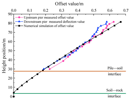
Figure 9.
Comparison of bridge pier deflection values (N = 14).
As can be seen from Figure 9, the numerical simulation of the pier from the pile-soil interface to 65 m height was generally consistent with the measured deflection. From the 65 m height to the top of the pier, the measured deflection increment of the pier appears to decrease locally, while the numerical simulation results still maintain the linear growth of the deflection, which is due to the fact that the model did not consider the interaction between the cap beam at the top of the pier and the bridge superstructure. In fact, when the bridge pier was deflected, the bridge superstructure would produce some lateral friction on the upper surface of the cap beam. Therefore, the displacement increment of the upper part of the pier was locally reduced. Overall, the numerical simulation results were in good agreement with the measured deflections, and the numerical model had high reliability.
4.2.2. Displacement and Deformation Characteristics of the Pier
Under the circulation of the reservoir water level, the deformation and instability of the bank slope will produce lateral thrust on the pile pier, resulting in the inclination and deviation of the pile pier towards the river center. The displacement and deformation characteristics of the pier are shown in Figure 10.
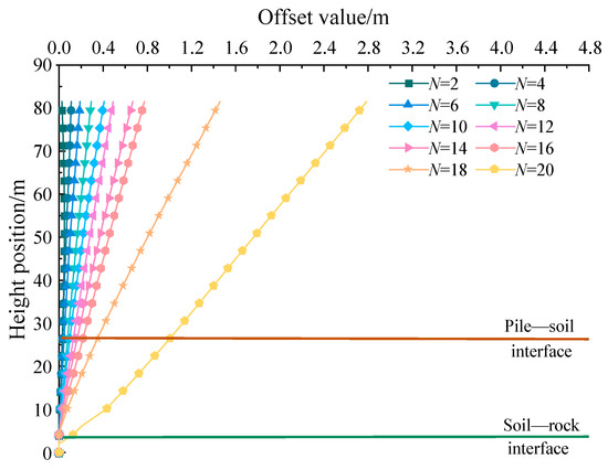
Figure 10.
Deformation characteristics of the bridge pier.
As can be seen from Figure 10, because of the rising and falling cycles of the reservoir water level, the pile pier line shape increasingly deviated from the original design position, and the overall deformation of the pile pier was characterized as follows: the height of the embedded foundation part of the pile displacement (0–3.5 m) was almost 0, the pile body from the soil-rock interface to the pile-soil interface (body height 3.5–26.36 m) under the action of horizontal deflection soil thrust, and the pier body from the pile-soil interface to the pier. The displacement of the pier body from the pile-soil interface to the top section (height 22.86~81.5 m) increases linearly. Near the soil-rock interface, the displacement of pile foundation increases sharply, and it was assumed that the most unfavorable position of pile foundation was near the soil-rock interface. When N = 20, there was an obvious inflection point in the pile foundation line shape from the soil-rock interface to the pile-soil interface. It can be seen that the pile foundation will be seriously deformed and damaged in the 20th reservoir water level lifting cycle.
In order to more clearly explore the indirect impact of the reservoir water level rise and fall cycle on the pier deflection, the variation law of pier top deflection under different times of the reservoir water level rise and fall cycle will be analyzed in combination with the deformation and instability of the bank slope. The variation of pier top deflection is shown in Figure 11.
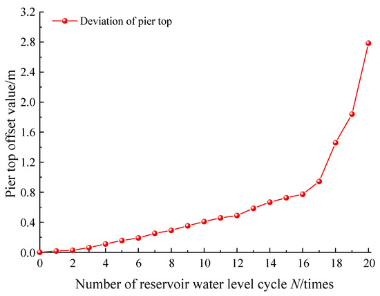
Figure 11.
The changing law of pier top deflection.
According to Figure 8 and Figure 11, the results show that the deviation of the pier top increases with the increase in the number of reservoir water level rise and fall cycles. In the first 15 cycles of reservoir level rise and fall, the bank slope was in a stable state, and the displacement of the top of the pier increased slowly during this period. After the 16th reservoir level rise and fall cycle, that is, after the first destabilization of the shore slope, the increment of the pier top offset suddenly changes, and its growth trend changes from a slow increase to a sharp increase. In the 17th to 19th water level rise and fall cycles, it was known from the previous analysis that although the slope was in a new stable state, the pile foundation played a certain anti-slip role in the deformation of the bank slope, the unbalanced thrust of the soil behind the pile gradually increased, and the deflection trend of the pier top was not moderated. In the 20th water level lift cycle, the second destabilization damage occurred on the bank slope behind the pile. According to the previous analysis, at this time the pile foundation had already undergone serious deformation damage. Therefore, the deflection tendency of the top of the bridge pier in this process was stronger than before.
5. Failure Mode of Bank Slope-Bridge Pile Foundation Interactions under Reservoir Water Level Cycling Conditions
The damage distribution and cracking of bridge pile foundations in the model were monitored to explore their damage patterns. The tensile damage on the back side of the pile foundation (back from the river center side) is shown in Figure 12. When N = 14, the pile foundation already showed obvious tensile damage and transverse cracks with exposed reinforcement near the soil-stone interface. The damage and cracks were initially concentrated near the soil-stone interface, then gradually developed towards the upper part of the pile and continued to produce transverse cracks. When N = 19, vertical cracks were produced at the end of transverse cracks, and in the 20th water level lift cycle (the second instability of the slope), the vertical cracks were connected with transverse cracks, the concrete in the tensile zone of the pile foundation failed in a large area, and the tensile and compressive stresses in the longitudinal reinforcement of the pile foundation reached the ultimate state of 460 MPa. Finally, the shear damage occurred in the upper part of the soil-stone interface of the pile foundation, and the angle between the damaged surface and the horizontal plane was about 60°.
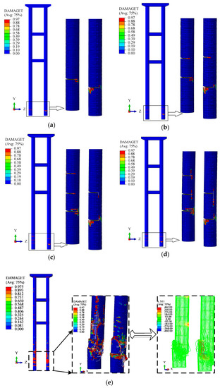
Figure 12.
Tensile damage to the pile foundation. (a) N = 14, (b) N = 16, (c) N = 18, (d) N = 19, and (e) N = 20.
6. Comprehensive Reinforcement Treatment Method
According to the damage development law and damage mode of the pile pier, combined with the characteristics of bank instability in a Yangtze River Bridge reservoir area of the Three Gorges, the vulnerable position of the pile pier is near the “rock-soil” intersection, and the landslide management is proposed to use soil removal and anti-slip pile reinforcement measures. For the characteristics of bridge pier deflection, the comprehensive deflection correction reinforcement method of pushing deflection correction, adding pile foundation, expanding the pile bearing, and increasing the pier cross-sectional area is proposed.
6.1. An Additional Anti-Slip Pile Reinforcement Method Is Used for Bank Slip
The common anti-slide pile (CASP) is the most widely used, with a simple structure, an obvious support effect, and mature design theory and construction technology, as shown in Figure 13. It was mainly used for small or medium-sized landslides and slopes without strict space requirements [25,26,27].
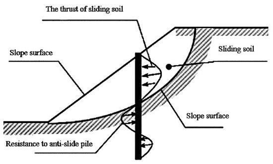
Figure 13.
Stress diagram of an anti-slide pile.
The simplified model of an anti-slide pile and landslide can be seen in Figure 14.
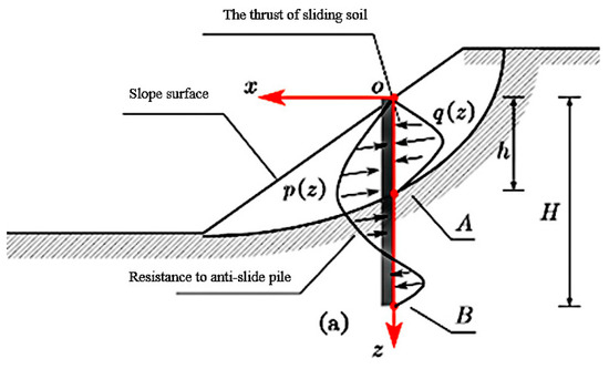
Figure 14.
Stress model of an anti-slide pile and landslide (simplified).
means the landslide thrust, which can be expressed by Equation (6).
According to the geological investigation report, the overall thickness of the shore slope cover layer of the bridge site’s 3#~6# pier section was larger. Therefore, it was suggested that effective retaining measures be taken between pier 4#–5# and pier 6#–7# and appropriate unloading between pier 2#–3# and pier 3#–4#. Two groups of 22 anti-slip piles were set between pier 4# and pier 5#. Reinforcement of C40 reinforced concrete anti-slip piles with a 2 m diameter and 38 m pile length. Twelve anti-slip piles in two rows were set up on the bank side of pier 6#. Reinforcement of C40 reinforced concrete anti-slip piles with 2 m diameter and a row of C40 reinforced concrete piles with 2 m diameter and 33 m length between pier 6# and pier 7#, a total of 11 piles for reinforcement. The pile distance along the centerline of the bridge road was 4 m, and the anti-slip piles were not less than 14 m, as shown in Figure 15.
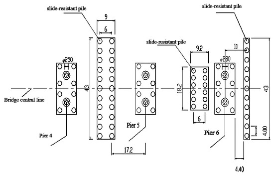
Figure 15.
Layout plan of an anti-slide pile.
6.2. The Main Girder Jacking Correction Method Is Used for Bridge Pier and Main Girder Deflection Disease
Once a bridge was subjected to a landslide, the substructure became eccentric, causing the upper portion of the bridge to be too eccentric and not sufficiently resistant to overturning, which led to the overall overturning of the bridge. If the bridge superstructure was separated from the substructure and then the bridge was moved horizontally to reset it, the eccentricity could be corrected and the original positioning and structural forces of the bridge could be restored. In practical engineering, a PLC synchronized jacking system was often used to control the jacks for separation and horizontal reset operations, a technique also known as jacking correction technology. A complete bridge jacking system usually includes five major components: a support system, a PLC hydraulic synchronous jacking system, a sliding device system, a limit system, and a monitoring system, as shown in Figure 16.
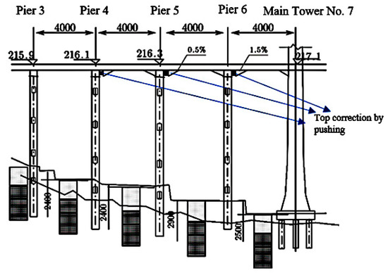
Figure 16.
Schematic diagram of the overall longitudinal pushing and deviation correction.
6.3. The Pier Body Disease Using the Increased Section Treatment Method
The 4#~6# pier body was reinforced with C35 wrapped concrete; the thickness of the outsourced concrete was 0.5 m; the height of the outsourcing was 0.5m from the bottom of the first tie-beam of the cover beam; and the reinforcement was set up with C25 reinforcement; the depth of drilling was 470 mm; the diameter of drilling was 30 mm; and the circumference of the pier column needed to be chiseled before the reinforcement was planted; the thickness of the chisel was about 10 mm; the height of the outsourced concrete of pier 4#~6# was 26.5 m, 27.5 m, and 30 m, respectively. The specific reinforcement scheme is shown in Figure 17.
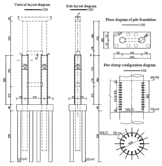
Figure 17.
Reinforcement drawing for 4#~6# pier shafts.
6.4. An Additional Pile Reinforcement Method Is Used for Foundation Damage
The additional pile foundation reinforcement method was used to increase the foundation bearing capacity by adding precast concrete piles or on-site construction bored piles around the original pile foundation and expanding the original pile cap to connect with the pile top, so that the new pile foundation can bear part of the bridge deck pressure. As can be seen from Figure 18, the foundation for 4#~6# pier piles was reinforced on the original pile foundation, and 4 C35 reinforced concrete pile foundations were added on the bank and river sides, respectively, and the reinforced foundation. The reinforced foundation adopted a 2.0 m diameter bored pile; the reinforced pile of pier 4# was 34 m long; the reinforced pile of pier 5# was 32 m long; and the reinforced pile of pier 6# was 32 m long.
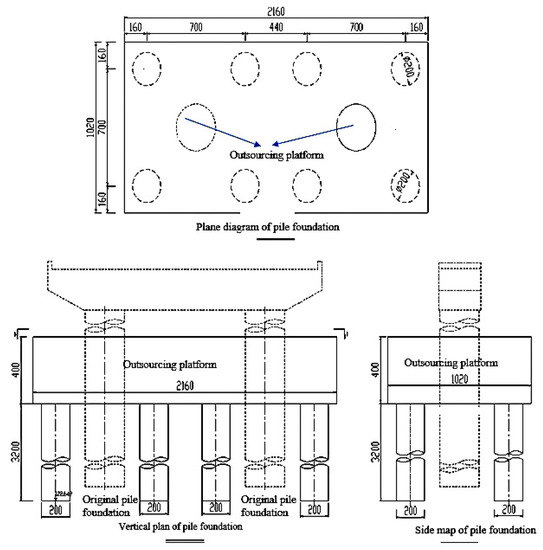
Figure 18.
Additional pile foundation and cushion cap reinforcement layout for 4#~6# pier piles.
6.5. Comprehensive Reinforcement Effect Analysis
The bank slope was in a stable condition after the soil removal and anti-slip pile reinforcement treatment, and the substructure was reinforced by adding pile foundation, expanding the bearing platform, and increasing the pier section, which greatly improved the bearing capacity and stability.
From Figure 19, the bridge inspection and monitoring results show that the above methods have a good effect on the reinforcement and management of a landslide-damaged bridge, among which the relative displacement of pier 6# was the most obvious change; the upstream and downstream sides of the pier top were reset by 33.5 cm and 33.0 cm, respectively; the upstream and downstream sides of the pier bottom near the ground were receded by 5.1 cm and 4.2 cm, respectively; and the relative displacement of pier and beam was reduced from 62.1 cm to 28.3 cm.
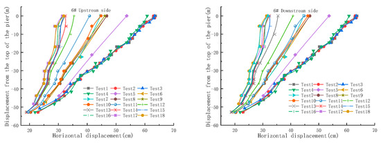
Figure 19.
Alignment measurement results of upstream and downstream pier columns of the 6# pier.
7. Conclusions
In this paper, for a Yangtze River Bridge in the Three Gorges reservoir area, the FEM-SPH conversion coupling algorithm is used to establish a three-dimensional finite element model of the bank slope and bridge, simulating the whole process of bank slope deformation, slip, and instability evolution under the reservoir water level rise and fall cycle, revealing the interaction mechanism between bank slope slip and bridge pile foundation, studying the bridge pier deflection law and failure mode, and obtaining the following conclusions:
- (1)
- The FEM-SPH conversion coupling algorithm can simulate the whole slope process, from the initial deformation slip to the deterioration of geotechnical properties leading to the final instability. It is more intuitive and accurate than the traditional criterion by completely converting the finite element mesh of the sliding area into SPH particles as the slope instability criterion;
- (2)
- The first instability damage will occur during the 16th water level lift cycle. In the 17th to 19th water level lift cycles, the slope is in a new steady state, but the unbalanced soil thrust on the pile foundation gradually increases, and the bridge pile foundation plays an anti-slip role in the slope deformation instability during the 20th water level lift cycle. The second type of instability damage will occur;
- (3)
- The overall deformation of the pile pier is characterized as follows: the displacement of the pile body in the bedrock embedded section is almost zero; the pile body is displaced horizontally from the soil-rock interface to the pile-soil interface; and the displacement of the pile body is linearly increasing from the pile-soil interface to the top of the pier. With the deformation, slippage, and instability of the slope, the deflection of the top of the pier shows a trend of “slow increase-surge”, and the increment of the deflection changes from slow increase to surge during the first destabilization of the bank slope;
- (4)
- Pile damage and cracking occur first at the soil-rock interface of the pile foundation and then gradually develop upward; with the deformation and destabilization of the bank slope under the action of the reservoir water level cycle, the pile foundation develops from transverse cracks to mixed cracks until the second destabilization of the bank slope occurs in the process of damage, the pile foundation tensile area fails on a large scale, shear damage occurs at the upper part of the soil-rock interface, and the angle between the damage surface and the horizontal plane is about 60°. Therefore, during the operation of the bridge, the structural performance monitoring at the soil-rock interface of the pile foundation should be strengthened, and the later remediation should focus on the reinforcement treatment at this location;
- (5)
- By relying on the bridge rescue project for the Three Gorges reservoir area landslide, the comprehensive reinforcement treatment method of the bridge structure was studied. The deflection of piers and main girders was corrected by jacking the main girders, piers were treated by increasing the cross-section; foundations were reinforced by adding pile foundations; and bank slips were reinforced by adding anti-slip piles. After adopting the comprehensive reinforcement treatment described in this paper, the bridge pier of a Yangtze River Bridge in the reservoir area has a good restoration effect, among which pier six has the most obvious treatment effect. The top upstream and downstream sides of the pier are restored to 33.5 cm and 33.0 cm, respectively, and the bottom upstream and downstream sides of the pier near the ground are restored to 5.1 cm and 4.2 cm, respectively. After the soil removal and anti-slip pile reinforcement treatment, the bank slope is in a stable state. Through reinforcement measures such as adding a pile foundation, enlarging the bearing platform, and expanding the pier section, the bearing capacity and stability of the substructure were greatly improved. The bridge inspection and monitoring results show that the above methods are effective for the reinforcement and treatment of landslide-damaged bridges.
Author Contributions
Conceptualization, S.L. and W.W.; methodology, G.Y.; software, G.Z. (Gaofeng Zhang) and A.S.; validation, W.L.; formal analysis, S.L., G.Y. and T.Q.; investigation, W.W., G.Z. (Ganping Zhou); resources, G.Z. (Ganping Zhou); data curation, A.S. and T.Q.; writing—original draft preparation, S.L. and W.W.; writing—review and editing, A.S. and G.Z. (Ganping Zhou); visualization, W.L.; supervision, T.Q., L.Z.; project administration, G.Y. and S.L.; funding acquisition, S.L., G.Y. and W.W. All authors have read and agreed to the published version of the manuscript.
Funding
This paper was founded by Chongqing Talent Plan Project (Grant No. cstc2022ycjh-bgzxm0124), Open Fund of State Key Laboratory of Mountain Bridge and Tunnel Engineering (Grant No. SKLBT-YF2105), Team Building Project for Graduate Tutors in Chongqing (Grant No. JDDSTD2022003), Joint Training Base Construction Project for Graduate Students in Chongqing (Grant No. JDLHPYJD2020004) and Research and Innovation Program for Graduate Students in Chongqing (Grant No. CYS22392 and 2022S0007).
Data Availability Statement
The data used to support the findings of this study are available from the corresponding author upon request.
Acknowledgments
Special thanks to the reviewers for their valuable comments. We thank the State Key Laboratory of Mountain Bridges and Tunnels and the experts for their precious suggestions on the paper and the reviewers for their hard work.
Conflicts of Interest
The authors declare no conflict of interest.
References
- Deng, H.F.; Zhou, M.L.; Li, J.L.; Sun, X.S.; Huang, Y.L. Creep degradation mechanism by water-rock interaction in the red-layer soft rock. Arab. J. Geosci. 2016, 9, 601. [Google Scholar] [CrossRef]
- Huang, D.; Gu, D.M. Influence of filling-drawdown cycles of the Three Gorges reservoir on deformation and failure behaviors of anaclinal rock slopes in the Wu Gorge. Geomorphology 2017, 295, 489–506. [Google Scholar] [CrossRef]
- Wang, H.L.; Xu, W.Y. Stability of Liangshuijing landslide under variation water levels of Three Gorges Reservoir. Eur. J. Environ. Civ. Eng. 2013, 17 (Suppl. 1), s158–s177. [Google Scholar] [CrossRef]
- Wang, H.B.; Sassa, K. Rainfall-induced landslide hazard assessment using artificial neural networks. Earth Surface Process. Landf. 2006, 31, 235–247. [Google Scholar] [CrossRef]
- Wu, S.R.; Shi, L.; Wang, R.J.; Tan, C.X.; Hu, D.G.; Mei, Y.T.; Xu, R.C. Zonation of the landslide hazards in the forereservoir region of the Three Gorges Project on the Yangtze River. Eng. Geol. 2001, 59, 51–58. [Google Scholar] [CrossRef]
- Ding, X.L.; Fu, J.; Zhang, Q.H. Stability analysis of landslide in the south end of Fengjie Highway Bridge with fluctuation of water level of Three Gorges Reservoir. Chin. J. Rock Mech. Eng. 2004, 17, 2913–2919. [Google Scholar]
- Miao, F.S.; Wu, Y.P.; Li, L.W.; Tang, H.M.; Li, Y.N. Centrifuge model test on the retrogressive landslide subjected to reservoir water level fluctuation. Eng. Geol. 2018, 245, 169–179. [Google Scholar] [CrossRef]
- Kafle, L.; Xu, W.J.; Zeng, S.Y.; Nagel, T. A numerical investigation of slope stability influenced by the combined effects of reservoir water level fluctuations and precipitation: A case study of the Bianjiazhai landslide in China. Eng. Geol. 2022, 297, 106508. [Google Scholar] [CrossRef]
- Xue, Y.; Miao, F.S.; Wu, Y.P.; Dias, D. Dynamic stability assessment of reservoir colluvial landslide using a hypoplastic clay constitutive model considering the effects of drying-wetting cycles on the hydro-fluctuation belt. Eng. Geol. 2022, 307, 106791. [Google Scholar] [CrossRef]
- Wang, H.Y. Study on Stability of High and Steep Slope in Mountain Reservoir. Build. Struct. 2017, 47, 486–490. [Google Scholar]
- Liu, D.Z.; Hu, X.L.; Zhou, C.; Xu, C.; He, C.C.; Zhang, H.; Wang, Q. Deformation mechanisms and evolution of a pile-reinforced landslide under long-term reservoir operation. Eng. Geol. 2020, 275, 105747. [Google Scholar] [CrossRef]
- Muszyński, Z.; Rybak, J. Horizontal Displacement Control in Course of Lateral Loading of a Pile in a Slope. IOP Conf. Ser. Mater. Sci. Eng. 2017, 245, 032002. [Google Scholar] [CrossRef]
- Kozubal, J.; Pula, W.; Wyjadlowski, M.; Bauer, J. Influence of varying soil properties on evaluation of pile reliability under lateral loads. J. Civ. Eng. Manag. 2013, 19, 272–284. [Google Scholar] [CrossRef]
- Diao, X.H.; Zhu, C.; Yu, Y.; Mao, X.B. Analysis of deformation characteristics of anti-slide piles under the action of seepage force. Sci. Technol. Eng. 2017, 17, 133–138. [Google Scholar]
- Sawant, V.A.; Shukla, S.K. Effect of Edge Distance from the Slope Crest on the Response of a Laterally Loaded Pile in Sloping Ground. Geotech. Geol. Eng. 2014, 32, 197–204. [Google Scholar] [CrossRef]
- Xing, L.; Wang, D.Y.; Duan, L.L.; Wang, L. Lateral cumulative displacement of wharf pile group under wetting-drying cycles and horizontal cyclic loading. Sci. Technol. Eng. 2021, 21, 8166–8175. [Google Scholar]
- Liu, A. Study on the force performance of bridge foundation across the reservoir area. Highway 2022, 67, 243–248. [Google Scholar]
- Zhou, G.P. Study on Damage Mechanism and Maintenance Method of Bridge Substructure under Loading Reservoir Bank Landslide. Master’s Thesis, Chongqing Jiaotong University, Chongqing, China, 2020. [Google Scholar]
- Xia, C.Z.; Shi, Z.M.; Zheng, H.C. An improved smooth particle hydrodynamics method for modelling crack propagation in layered rock cells and slopes. Bull. Eng. Geol. Environ. 2023, 82, 129. [Google Scholar] [CrossRef]
- Fang, J.N.; Parriaux, A.; Rentschler, M.; Ancey, C. Improved SPH methods for simulating free surface flows of viscous fluids. Appl. Numer. Math. 2008, 59, 251–271. [Google Scholar] [CrossRef]
- Hu, M.; Gao, T.; Dong, X.W.; Tan, Q.T.; Yi, C.; Wu, F.; Bao, A.H. Simulation of soil-tool interaction using smoothed particle hydrodynamics (SPH). Soil Tillage Res. 2023, 229, 105671. [Google Scholar] [CrossRef]
- GB 50010-2010; Code for Design of Concrete Structures. China Architecture & Building Press: Beijing, China, 2015.
- Tu, Y.L.; Liu, X.R.; Zhong, Z.L.; Wang, S.; Wang, Z.J.; Ke, W. Experimental study on strength and deformation characteristics of silty clay during wetting-drying cycles. Rock Soil Mech. 2017, 38, 3581–3589. [Google Scholar]
- Zhou, Y.F.; Deng, J.H.; Cui, Y.L.; Zheng, H.C.; Chen, T. Instability Criterion of Three-Dimensional Slope Based on Strength Reduction Method. Rock Soil Mech. 2014, 35, 1430–1437. [Google Scholar]
- Li, J.; Chen, S.X.; Yu, F.; Jiang, L.F. Reinforcement Mechanism and Optimisation of Reinforcement Approach of a High and Steep Slope Using Prestressed Anchor Cables. Appl. Sci. 2019, 10, 266. [Google Scholar] [CrossRef]
- Galli, A.; di Prisco, C. Displacement-based design procedure for slope-stabilizing piles. Can. Geotech. J. 2013, 50, 41–53. [Google Scholar] [CrossRef]
- Kourkoulis, R.; Gelagoti, F.; Anastasopoulos, I.; Gazetas, G. Slope stabilizing piles and pile-groups: Parametric study and design insights. J. Geotech. Geoenvironmental Eng. 2011, 137, 663–677. [Google Scholar] [CrossRef]


Disclaimer/Publisher’s Note: The statements, opinions and data contained in all publications are solely those of the individual author(s) and contributor(s) and not of MDPI and/or the editor(s). MDPI and/or the editor(s) disclaim responsibility for any injury to people or property resulting from any ideas, methods, instructions or products referred to in the content. |
© 2023 by the authors. Licensee MDPI, Basel, Switzerland. This article is an open access article distributed under the terms and conditions of the Creative Commons Attribution (CC BY) license (https://creativecommons.org/licenses/by/4.0/).