Article

Research on the Seismic Isolation Effect of the Ring Spring–Friction Pendulum Bearing in the Dakai Underground Subway Station

Department of Civil Engineering, Northeast Forestry University, Harbin 150040, China
*
Author to whom correspondence should be addressed.
Appl. Sci. 2023, 13(12), 7093; https://doi.org/10.3390/app13127093
Submission received: 24 April 2023 / Revised: 23 May 2023 / Accepted: 6 June 2023 / Published: 13 June 2023

Abstract

:
During strong earthquakes, the vertical seismic force becomes an essential factor affecting shallow underground structures that cannot be ignored. In this situation, it is proposed that ring spring–friction pendulum two-way seismic isolation bearings be set up at the bottom of such structures. Targeting the Dakai underground station and the Kobe earthquake, a soil-structure force model was established based on the damage to the underground structure and dynamic simulation was carried out using Abaqus software. The advantages of the ring spring–friction pendulum bearing over the ring spring bearing alone and the friction pendulum bearing alone were compared. The simulation results showed that the structure displayed a good seismic isolation effect in both horizontal and vertical directions after setting the ring spring–friction pendulum bearing. The deflection in the midspan of the roof reduced to less than 5 cm, the horizontal relative displacement of the structure reduced to less than 3 cm, there was no obvious damage to the structure, the axial pressure ratio of the mid-pillar reduced to less than 0.5, the axial force on the mid-pillar reduced by more than 50%, and the shear force reduced by more than 30%. In addition, by comparing the damage to the structure after setting the annular spring bearing and the friction pendulum bearing, we found that a vertical seismic isolation device is more crucial than a horizontal seismic isolation device for shallow underground structures. Setting a vertical damping device can make the structure retain part of the ductility and reduce the damage to the structure, so the ground vertical seismic mitigation design should be strengthened when a shallow underground structure is designed.

1. Introduction

With the widespread development and use of underground space in China, underground structures are facing a huge challenge—earthquakes. Considering the constraints of the surrounding soil and the decrease in earthquakes with increasing burial depth, people used to think that the seismic performance of underground structures is much better than that of above-ground structures. Therefore, the safety of underground structures during earthquakes did not receive sufficient attention for a long time, and most of the underground structures that were built in the early years were not designed for seismic protection. The existing earthquake damage shows that the current subway station structures are not safe when strong earthquakes occur. For example, three aqueducts and two tunnels were severely damaged in the 1906 San Francisco ms 8.3 earthquake [1]. In the ms 8.1 earthquake in Mexico in 1985, 13 of 101 subway stations went out of service, imperceptible cracks appeared at the joints of subway tunnels and station structures, and fracture damage occurred in some side walls and structural top slabs in subway stations on soft ground [2]. In the ms 7.2 Kobe earthquake, which occurred in Japan in 1995, the most serious damage was caused to the underground structures in Kobe. A large number of underground works, such as subways, underground parking lots, underground tunnels, and underground shopping streets, were damaged, with the most serious damage being to subway station structures [3]. The 1999 Kokkaieri (Izmit) earthquake in Turkey caused significant permanent deformation of subsurface structures and soils in the Adapazal region [4]. In the Wenchuan ms 8.0 earthquake in 2008, the main structure of four stations of the Chengdu subway was damaged, with many cracks in the station walls and water seepage at the cracks; the shield tunnel sections had obvious cracks, misalignment, anchor rod fractures, water seepage, and other earthquake damage phenomena, and the area of water seepage between the section and the circle increased [5].
Once earthquake damage occurs in underground structures, it not only causes huge casualties and property damage but also makes the post-earthquake repair work of underground structures even more difficult. Therefore, the aseismic design of underground structures is essential. After the Wenchuan earthquake, the engineering aseismic community reached a consensus that the application of aseismic technologies and energy dissipation technologies in engineering structures should be vigorously promoted, using aseismic elements or energy dissipation damping devices to consume most of the earthquake input energy and the main structural members only absorbing or storing a small portion of the kinetic and deformation energy so as to ensure the safety of the main structural members.
The research on seismic isolation technology started with ground building structures, among which typical seismic isolation devices are friction pendulum bearings, which have been widely used in many large-span space structures and bridge structures because of their low cost, simple construction, and high load-bearing capacity. In 1995, Zayas et al. [6] performed a finite element analysis of the seismic response of industrial storage tanks with FPB, and the results showed that FPB can not only reduce the risk of leakage or damage to the structure during an earthquake but also make the structure design more economical and reasonable. Dicleli [7,8] and Ingham [9] investigated the use of FPB for bridges in terms of strengthening techniques and economic benefits. The results showed that FPB can effectively attenuate seismic effects and is less costly than conventional structural ring springs, which were initially common in various mechanical components, such as artillery automatic floaters, slab casters buffers, and machine gun launchers [10,11,12]. In recent years, ring springs have also been gradually explored in the field of construction. A student apartment building at Victoria University of Wellington in New Zealand, which was installed with a ring spring column-based damper, could withstand a 6.5 magnitude earthquake, and the building still maintains its elastic deformation without damage [13]. Khoo, H.H. et al. [14,15] installed ring springs on sliding hinge joints of pure steel frame nodes to improve the joint members’ dynamic self-resetting performance and the nodes’ seismic performance. Fang et al. [16,17] developed a new ring spring system using a shape memory alloy (SMA) instead of conventional spring steel. They explored its mechanical properties and applied it to beam–column node connections.
The friction pendulum bearing and the ring spring bearing both show good seismic isolation performance in ground building structures, and the self-resetting performance of the friction pendulum and the superhigh load-bearing capacity of the ring spring are suitable for application in underground structures [18,19,20]. However, both can only show the effect of single-directional seismic isolation, and existing research shows that the subway station structure will be seriously damaged under the coupling effect of horizontal seismic action and vertical seismic force [21]. Therefore, a single-directional damping device does not meet the seismic requirements of underground structures. In order to achieve vertical seismic isolation and horizontal damping of the structure using the same device, this paper proposes a ring spring–friction pendulum seismic isolation bearing, in which the ring spring provides vertical seismic isolation and the friction pendulum provides horizontal damping. The self-oscillation period of the structure in the horizontal and vertical directions can be prolonged after setting the bearing at the bottom of the structure so as to reduce the transmission of seismic forces to the structure and achieve the purpose of protecting it.
In this paper, the mechanical performance equations of the ring spring–friction pendulum bearing in the horizontal and vertical directions are proposed, and the forces of the ring spring–friction pendulum bearing under cyclic loading are simulated using Abaqus finite element software. The simulation results are compared with the theoretical equations to verify the correctness of the formulas and to provide a theoretical basis for the application of the ring spring–friction pendulum bearing to construction. Next, taking the Dakai station and the Kobe earthquake as the engineering background, the damage to the subway station structure in the actual earthquake is simulated by combining seismic acceleration loading with resonant force loading in Abaqus software, and then the vibration response of the structure is obtained by loading the structure with the bearings installed in the same way so as to illustrate the seismic mitigation effect of the ring spring–friction pendulum. The purpose of this paper is to achieve horizontal-vertical bidirectional seismic isolation of subway stations by proposing a new combination of seismic isolation bearings and to provide a reference for seismic isolation studies of underground structures. At the same time, the research in this paper highlights the differences in the causes of damage between underground structures and surface structures during earthquakes and that the vertical seismic force is a key factor for underground structural damage, which should be emphasized in the future seismic design of underground structures.

2. Mechanical Properties of Ring–Friction Pendulum Isolation Bearings

2.1. Introduction of the Ring Spring–Friction Pendulum Vibration Isolation Bearing

As shown in Figure 1, the ring spring–friction pendulum bearing mainly consists of two single bearings. Each single support contains a friction pair and a ring spring. The friction surface of the two friction pairs is symmetrical. This friction pendulum design has a better anti-tip effect than the traditional curved friction pendulum and ensures the ring spring is not eccentrically pressed.

2.2. Vertical Seismic Isolation Performance of the Ring Spring–Friction Pendulum Bearing

According to the study of Du Xiu Li [21], shear damage occurs in the soil above the Dakai station during a strong earthquake, and the earthquake peaks at about 6 s. The plastic shear strain runs through the soil above. The soil loses shear resistance. The gravity of the overlying soil acts on the top of the structure under the vertical earthquake. Due to the sudden increase in vertical pressure on the structure, the structure’s ductility in the horizontal direction reduces and the shear resistance weakens, which causes compression-shear damage in the weak part of the structure. Therefore, by setting vertical isolation devices, the vertical stiffness of the isolated structure can be reduced, thus reducing the self-oscillation frequency of the structure, which ultimately serves the purpose of reducing the transmission of vertical seismic effects.
During an earthquake, the overlying soil of the structure loses its shear capacity, and eventually, the overlying soil becomes an additional structure mass. As a result, the stiffness of the soil and structure is much greater than that of the vibration isolation bearing. Therefore, this paper considers the soil and structure as one part. The seismic isolation structure is considered as a single-degree-of-freedom viscoelastic system [22], and the force diagram of the system is shown in Figure 2.
When the single-degree-of-freedom viscoelastic system is subjected to dynamic load, the transfer rate equation is as follows:
TR = 1 + [ 2 ξ ( ω / ω n ) ] 2 [ 1 ( ω / ω n ) 2 ] 2 + [ 2 ξ ( ω / ω n ) ] 2 1 / 2
where ξ is the damping ratio of the seismic isolation structural system, ω is the frequency of dynamic loads, and ω n is the self-vibration frequency of seismically isolated structures.
It can be seen from the above equation that transmissibility TR is a function of the frequency ratio ω / ω n . Figure 3 shows the function curve of transmissibility TR and the frequency ratio ω / ω n for different damping ratios. It can be seen from the figure that damping is the main factor affecting transmissibility when the frequency ratio is in the range of [ 1 , 2 ] . When the damping ratio is larger, the transmissibility is larger. However, when the frequency ratio is less than 1, the transmissibility of the resonant force is always less than 1, no matter how much the damping is. Therefore, in order to make the transmissibility of dynamic load smaller, the stiffness K of the system should be adjusted to as large a value as possible so that the self-oscillation frequency of the system reduces to below ω 2 / 2 . Because in this frequency range, although the greater the damping, the higher the transmissibility, the impact is small and the increase is not large; in this case, the frequency ratio is the key factor affecting the transmissibility TR [23,24].
The vertical seismic isolation performance of the ring spring–friction pendulum bearing is mainly provided by the ring spring. When the vertical deformation of the loop spring is s, the axial force on the ring spring can be expressed as follows:
F = 2 π E K c tan β n 0 ( D 01 A 1 + D 02 A 2 ) s
The stiffness of the ring spring is calculated as follows [25]:
K v = 2 π E K c tan β n 0 ( D 01 A 1 + D 02 A 2 )
where β is the cone angle of the circle; Kc is a calculation factor ( K c = tan ( β ± ρ ) ), ρ is the angle of friction, take “+” when the spring is under pressure and “-” when the spring is restored; D01 and D02 are the diameters of the central rings of the inner and outer rings, respectively; A 1 and A 2 are the cross-sectional areas of the inner and outer rings, respectively; and n 0 is the number of groups of circles.
In order to further verify the mechanical properties of the ring springs, we conducted numerical simulation studies of the ring springs in Abaqus software. We calculated the total self-weight of the structure and the overlying soil of each section of the Dakai station as 860,548 kg, and each ring spring needed to bear 5.6 × 10⁶ N according to the design of the rare earthquake with a seismic fortification intensity of 7 degrees. The sizes of the ring springs are shown in Figure 4a. The total height of the ring spring was 2340 mm, and the maximum diameter of the ring was 1500 mm. The maximum vertical compression of the ring spring was 480 mm in the normal working condition, and the interval between each ring was 2 mm. The vertical compression in the ultimate bearing capacity condition was 500 mm. The material of the ring spring was ISO60Si8 spring steel, which is widely used in the mechanical engineering. Its density is 7850 kg/m3, modulus of elasticity is 206 GPa, Poisson’s ratio is 0.33 The elastic-plastic model of Abaqus was used for the ring spring, with yield stress 1375 MPa and the mesh cell of type C3D8I. The normal contact between the rings was hard contact, and separation was allowed after contact. According to the experimental results of Professor Wang Wei of Tongji University, “sandblasting without lubricant treatment” should be performed between the inner and outer rings. The toroidal spring is more beneficial to structural building seismic isolation, so a penalty function was chosen tangentially between the contact surfaces of the toroidal spring. The friction coefficient was entered as 0.1 [26]. A fixed restraint was set at the bottom of the ring spring, a displacement load was applied to the upper surface, and the rotation of all circles around the central axis was restricted; the three-dimensional entity diagram is shown in Figure 4b. In order to accurately observe the variation of stress in the ring along the thickness direction, the mesh of the ring needs to be detailed. We divided the mesh into four columns in the thickness direction of the ring, as shown in Figure 5. After the model was built, we loaded it with vertical displacements, starting from 0 to 480 mm and 500 mm and then unloaded it. Finally, we output the load–displacement curves for both conditions.
As seen in Figure 6, there was little discrepancy between the formula calculation and finite element simulation in the normal working condition (480 mm), which can confirm the correctness of the formula. The loading stiffness of the ring spring in the normal working condition was 13.2 kN/mm. In the ultimate limit condition (500 mm), the load and displacement were correlated linearly during the initial loading, and the finite element simulation results and the formula calculation results were basically consistent. After loading to 480 mm, the spring stiffness rose slowly and then increased sharply when the load approached 500 mm. The final bearing capacity was 8013.7 kN. When the ring spring reached the limit of bearing capacity, the gap between the ring and the spring gradually decreased and they finally fit completely; at this time, the ring spring lost the deformation capability of the spring and became a hollow cylinder, and the stiffness and bearing capacity suddenly increased. However, this change helped protect the safety of the structure and the bearing.

2.3. Horizontal Seismic Isolation Performance of the Ring Spring–Friction Pendulum

The horizontal seismic isolation performance of the ring spring–friction pendulum bearing is mainly provided by the friction pendulum, which is slightly different from the traditional friction pendulum. Figure 7 shows the force diagram of the modified friction pendulum. In this paper, the friction of the slider in the friction pendulum was regarded as the classical Coulomb friction. The following assumptions were proposed:
(1)
The value of the frictional force is proportional to the upper normal load and irrelevant to the contact area.
(2)
The value of the frictional force is irrelevant to the speed of the object’s movement
(3)
The coefficient of friction is constant.
Each friction pendulum contains two friction pairs, and the friction surface of each friction pair is at opposite angles. This design ensures that no matter if the two sliders move to the left or to the right during the sliding process, each slider can be in contact with the friction surface, making the structure more stable and less likely to tip over when subjected to horizontal forces. This paper assumes that the axis of symmetry of the friction pendulum intersects the vertical line of the friction surface at O, P is the center of gravity of slider A and slider B, the length of OP is R, and the inclination of the friction surface is θ. So, the horizontal sliding displacement of the slider can be expressed as D = Rsinθ, W is the structural gravity of the friction pendulum, the two sliders are subjected to positive pressures T1 and T2 and ring spring support forces N1 and N2, F is the horizontal restoring force of the two friction pendulum bearings’ combined force, f1 and f2 are the friction forces on the slider, and Kv is the stiffness of the ring spring [27,28].
According to the principle of bending moment balance, the following formula can be obtained:
F R cos θ + 2 T 1 D cos θ = ( f 1 + f 2 ) R + ( N 1 + N 2 ) R
and
T 1 = N 1 cos θ N 1 = W 2 K D ( t ) sin θ N 1 + N 2 = W f 1 + f 2 = μ W cos θ sgn
Substituting Equation (5) into Equation (4), the horizontal restoring force can be expressed as the following equation:
F = 2 K v D tan θ + μ W sgn ( D )
and
sgn = 1 0 1 θ > 0 θ = 0 θ < 0
The equivalent stiffness of the friction pendulum can be expressed as the following equation:
K h = F D = 2 K v tan θ + μ W sgn ( D ) D
The hysteresis performance of the modified friction pendulum under cyclic loading in Abaqus software was simulated, and the correctness of the derivation of the above equation was verified. During the simulation, four models were created. A comparison was made by varying the friction surface’s inclination angle θ, the friction coefficient of the friction surface μ, and the stiffness of the lower ring spring Kv. Next, the simulation results were compared with the formula. The critical parameters of the model are shown in Table 1. Figure 8 shows the dimensional drawing and the friction pendulum’s 3D solid finite element model. The size of the four friction pendulums was the same, the material was Q345 steel, the modulus of elasticity was 200 GPa, Poisson’s ratio was 0.33, the yield strength of steel was 345 MPa, and the density 7850 was kg/m3. In order to ensure that the two upper support plates moved up and down at the same time, a rigid shell surface was placed on the upper part of the support plate. All loads were transferred to the lower friction pendulum through the shell surface. The bottom surfaces of the two sliders were coupled to the reference points RP1 and RP2, and then two fixed reference points RP3 and RP4 were set. A spring connection was set between the two reference points to simulate the lower ring spring stiffness. The rigid body shell on the upper surface of the support was in close contact with the two upper support plates, and the shell surface was frictionless with the support surface.
The simulation process involved two analysis steps. The first step simulated the upper load on the support by applying a point force W to the shell. In the whole first analysis step, only the displacement deformation of the model in the Y direction was allowed, and the model’s other five freedoms were limited. In the second step, the freedom in the X direction of the support plates was released, and the displacement period load along the X direction was applied to the support plate. Finally, the hysteresis curve of the friction pendulum was plotted by outputting the time course curve of the restoring force of the support plate and the time course curve of the displacement in the X direction of the support plate.
The formula was more closely matched by the hysteresis curve produced following periodic loading in the horizontal direction, as shown in Figure 9, and the equivalent stiffness derived from both was the same, confirming the correctness of the formula.

3. Finite Element Model Analysis

3.1. Structural Modeling

In order to evaluate the seismic isolation effect of the ring spring–friction bearing, this paper built a model of the Japanese Dakai station in Abaqus software and simulated the damage to the Dakai station during the Kobe earthquake. The construction of the Dakai station was performed using the open excavation method [29]; the burial depth was 4.8 m; the building adopted a closed frame structure; the thickness of its top and bottom slabs was 800 mm and 850 mm, respectively, and the reinforcement rate was 1%; the thickness of its side walls was 700 mm, and the reinforcement rate was 0.8%; the distance between the mid-pillars of the Dakai station is 3.5 m; and the cross-section size was 600 mm × 400 mm, and the reinforcement rate was 6.0% [21,30]. In Abaqus finite element software, a three-section underground station model was established whose longitudinal length was 10.5 m, as shown in Figure 10.
The concrete in the station used the plastic damage model in Abaqus, and the rebar uses the Miss classical elastic-plasticity principal structure model, embedded in the concrete using Embedded constraints. According to the Japanese literature, the design strength of the concrete used in the mid-pillar was 23,520 kN/m2, the design strength of the concrete in the rest of the structure was 20,580 kN/m2, and the design yield strength of the steel reinforcement was 31.20 kN/cm2. Material experiments were conducted at the location of the mid-pillar after the earthquake to check the strength of the concrete. The hammering experiment measured a concrete strength of 37,240 kN/m2, and the cylinder compression experiment measured a concrete strength of 39,690 kN/m2 [29]. The concrete and reinforcing material characteristics are displayed in Table 2, which references simulation parameters from the published literature [31]. The axial movement of the structural model was limited, and a fixed end restraint was applied to the bottom of the seismic isolation bearing. According to the findings of the literature, after the overlying soil loses its shear properties during an earthquake, it affects the top of the structure by additional masses, so in this paper, in order to consider the worst form of force on the structure during an earthquake, all the masses of the overlying soil were given to the roof of the structure so as to simulate the inertial forces of the overlying soil during the earthquake. The mechanical parameters of the material are shown in Table 2 [31].

3.2. Design and Modeling of Seismic Isolation Bearings

In order to examine the seismic mitigation effect of the ring spring–friction pendulum bearing, in this paper, three types of seismic isolation structures were established. The three seismic isolation structures were, respectively, set up with friction pendulum, annular spring, and annular spring–friction pendulum bearings. According to the results in Section 2, the vertical stiffness and horizontal stiffness of the bearing were different when the bearing parameters were different. The size of the bearing model in this section was based on the design of the ring spring and friction pendulum in Section 2, the angle of the friction surface of the friction pendulum was 3°, and the friction coefficient was 0.04 [32]. The seismic bearings were arranged equally spaced at the bottom of the structure. The upper top surface of the bearing was connected with the bottom plate of the structure using Tie constraints, and there was no relative sliding between the bearing and the structure. The lower surfaces of the bearings were fixed. The front and rear bearings in each group of seismic bearings were separated by 7 m. The arrangement of the three bearings is shown in Figure 11. It should be emphasized that the bearing dimensions in the previous section do not necessarily achieve the best seismic isolation effect. The calculation should be repeated to get the best bearing parameters in practical application. According to the formula of the horizontal and vertical stiffness of the bearing, the equivalent horizontal stiffness of the isolated structure was calculated as 1.92 kN/mm, the horizontal self-oscillation period of the structure was 7.28 s, the equivalent vertical stiffness was 79.2 kN/mm, and the vertical self-oscillation period of the structure was 1.96 s. Based on the soil survey conducted by the Japan Railway Institute of Technology (JTRI) in the surroundings of the Dakai station, the yard where the Dakai station is located can be judged as a Class II yard. According to the Chinese Standard (GB 50011-2010) [33], the characteristic period of a Class II yard in the first design earthquake grouping is 0.35 s, so the design of the seismic isolation bearing is rational [23,34].

3.3. Earthquake Input

In order to simulate the real damage situation of the Dakai subway station underground, this paper adopted a combination of acceleration loading and resonance force loading. The acceleration time–history curves of the two earthquakes were input from the bottom of the model in the vertical direction, and the equivalent resonant force of the two earthquakes was loaded on one side of the structure in the horizontal direction; the force of the underground station during the earthquake is shown in Figure 12. The horizontal and vertical acceleration time curves in the Kobe earthquake were recorded based on the data from the earthquake observation station set up near the Dakai station, and the horizontal and vertical acceleration time–history curves of the Kobe earthquake are shown in Figure 13a and Figure 14a. The El Centro earthquake was also chosen as a reference. The horizontal and vertical acceleration time–history curves of the El Centro earthquake are shown in Figure 13b and Figure 14b. As shown in Figure 15, the vertical bandwidth of Kobe and El Centro earthquakes contain the vertical self-oscillation frequency of the structure. This indicates that the both earthquakes can effectively cause structural vibration. The frequency of the resonant force was taken as the main frequency of the two earthquakes, and the peak value of the resonant force was calculated according to the seismic active earth pressure formula mentioned in the Chinese Standard (NB 35047-2015) [35].
The seismic active earth pressure is calculated using the following equation:
F E = [ q 0 cos ψ 1 cos ( ψ 1 ψ 2 ) + 1 2 γ H 2 ] ( 1 + ξ a v / g ) C e
The structure was designed according to the seismic fortification intensity of 7 degrees under rare earthquakes, and the representative value of the horizontal design seismic acceleration av was 310 cm/s2. According to the formula in the Chinese Standards, Ce can be calculated as 0.426, FE as 295.3 kN/m, the axial length of the three-section station structure is 10.5 m, and then the active earth pressure acting on one side of the structure is 3.1 × 10 6 N . The horizontal acceleration time curves of the Kobe and El Centro earthquakes were Fourier-transformed to obtain the Fourier spectra shown in Figure 16, from which it can be seen that the main frequency of the Kobe earthquake wave was 1.16 Hz and the main frequency of the El Centro earthquake was 1.45 Hz. In order to be more realistic, the horizontal equivalent resonance force of the Kobe earthquake was amplitude-modulated. From Figure 12a, it can be seen that the Kobe earthquake reached its seismic peak at about 8.06 s, so the horizontal equivalent resonant force of the Kobe earthquake from 0 s to 4.3 s was adjusted to 1/3 of the seismic active earth pressure and the peak from 4.3 s to 8.6 s was adjusted to 2/3 of the seismic active earth pressure; the El Centro earthquake reached its seismic peak at about 2.12 s, so there was no need for amplitude modulation. The equivalent resonant force curves of the two earthquakes are shown in Figure 17.
The finite element simulation was divided into two analysis steps. The first analysis step applied gravity load to the structure, which caused pre-deformation of the seismic isolation bearing, and the second analysis step applied seismic load to the structure, which caused damage to the structure and the seismic isolation bearing started to work [36].
In order to comprehensively evaluate the seismic isolation effect of the combined ring spring and friction, this paper compared the superiority of the combined seismic isolation bearing to that of the friction pendulum bearing alone and the ring spring bearing alone according to the conditions shown in Table 3 [37].
Since the upper and lower sections of the mid-pillars are small and subject to significant shear and axial forces in the horizontal and vertical directions, they are the two dangerous sections to reach the ultimate bearing capacity first [32,38]. The upper and lower ends of the structural side walls are also subjected to significant bending moments and are critical cross-sections that need attention in seismic design. Therefore, observation points were set up at the locations shown in Figure 18 to output the axial and shear forces of each member, as well as the vertical and horizontal displacements of the structure, to analyze the effect of seismic isolators on structural deformation.

4. Analysis of Results

Figure 19 shows the deformation nephograms of conditions 1 and 2, as well as photographic documentation of the actual earthquake damage. The simulation results were similar to the actual earthquake damage results, indicating that the combination of acceleration loading and resonant force loading can better simulate the underground structure damage. In both working conditions, the mid-span deflection of the roof exceeded 2.5 m, and the maximum horizontal relative displacement was about 20 cm in both cases.
Here, we will compare the vertical and horizontal responses of the structure and analyze the advantages and existing problems of the three types of supports. In order to illustrate the seismic isolation performance, this paper defined the rate of internal force change to represent the improvement compared to the original structure after setting seismic isolation bearings. When the rate of change is positive, it indicates a greater internal force than the original structure. When the rate of change is negative, it indicates a smaller internal force than the original structure. The formula is:
R = F i F o F o
where R is the transformation rate of the internal force, Fi is the value of the internal force of the isolated structure, and Fo is the value of the internal force of the original structure.

4.1. Comparison of the Vertical Response of the Structure

Figure 20 shows the structural deformation of the Dakai station during two kinds of earthquakes after setting three kinds of seismic isolation bearings. It can be seen from the figure that during the two earthquakes, the mid-span deflection of the structure reduced after the friction pendulum bearing was set at the bottom of the structure. Therefore, the structure still had a large deformation and did not achieve the seismic isolation effect [39]. After setting the ring spring bearing, the span of the structure dropped by 26.4 cm during the El Centro earthquake and by 29 cm during the Kobe earthquake, which was a substantial reduction but still did not meet the norm. The Chinese Standard (GB 50010-2010) [40] that when the flexural member exceeds 9 m, the mid-span deflection is limited to 1/300, which does not meet the seismic requirements after setting the ring spring bearing. Moreover, after setting the ring spring–friction pendulum bearing, the span deflection is below 5 cm and the span deflection ratio is less than 1/300 [41,42].
Table 4 and Table 5 show the axial pressures of the side walls and mid-pillars in different conditions. First, from the data in the two tables, we can see that the axial force on the mid-pillar reduced after setting the seismic isolation bearing, and the axial force on the mid-pillar could be reduced by about 20~40% by setting the friction pendulum bearing only. However, the results of the fourth condition showed that during the El Centro earthquake, the axial force of the mid-pillar after the friction pendulum bearing was set was 4410 kN. At this time, the axial compression ratio of the mid-pillar was 0.78. According to the requirements of the Chinese Standard (GB 50011-2010), the axial compression ratio of the pillar of the frame-shear wall structure under the first-level seismic grade standard should be less than 0.75, so setting only the friction pendulum bearing cannot meet the seismic grade requirements.
After setting the ring spring bearing, the axial force of the mid-pillar reduced by about 40%. However, the axial force of the side wall increased by four times, which means that although the axial force of the mid-pillar reduces after setting the ring spring, the other parts of the structure will still be damaged under the strong horizontal seismic action, combined with the deformation of the structure. It can be seen that under the two-way seismic action, the mid-pillar is the first to lose the vertical bearing capacity. In addition, most of the vertical seismic action is applied to the end of the side wall, so only setting the vertical seismic isolation bearing for the subway station structure does not have a good effect of seismic reduction. Finally, the structure still bears most of the seismic action.
On the contrary, after setting the friction pendulum bearing, the axial force of the side wall significantly reduced, while the axial force of the mid-pillar did not significantly reduce. Moreover, a large deformation occurred in the span of the top plate of the structure, indicating that the mid-pillar of the structure was still subjected to most of the vertical load during the earthquake, and the bearing capacity of the side walls was not fully developed. Therefore, the seismic mitigation effect of the friction pendulum bearing and the ring spring bearing shows that setting the seismic isolation device in a single direction can only change the structure’s force distribution and cannot absorb the energy during the earthquake well.
After setting the ring spring–friction pendulum bearing, the advantages of the friction pendulum and the ring spring could be seen. The axial force of the mid-pillar reduced by more than 50%, while the axial pressure at the end of the side wall was slightly elevated. The compressive stress at the end of the side wall was 4.28 MPa in the Kobe earthquake and 3.57 MPa in the El Centro earthquake. During both earthquakes, the side wall concrete did not yield, which ensured structural integrity. Meanwhile , side walls bear most of the vertical seismic forces. , It avoided overall structural collapse caused by partial damage.

4.2. Comparison of the Structural Horizontal Response

Figure 21 shows the horizontal displacement–time curves between the upper and lower plates of the structure. The horizontal deformation was the largest of the three types of bearings after setting the ring spring bearing. The maximum horizontal relative displacement was 17.5 cm in the El Centro earthquake and 22.6 cm in the Kobe earthquake, which is smaller than the deformation in the original structure. However, the structure was still damaged, indicating that horizontal seismic isolation measures and vertical seismic isolation measures are essential for the underground structure. This shows that seismic isolation measures in both horizontal and vertical directions are essential for the underground structure, and seismic forces in both directions will cause great damage to the structure. The horizontal deformation of the structure was 10.6 cm in the El Centro earthquake and 9.5 cm in the Kobe earthquake after setting the friction pendulum bearing. The seismic design code for buildings stipulates that the elastic-plastic inter-story displacement angle limit of a reinforced concrete frame–isolated wall is 1/100, so it still does not meet the seismic code standard. After setting the ring spring–friction pendulum bearing, the horizontal inter-story relative displacement of the structure dropped to below 3 cm, which meets the code standard.
Table 6 and Table 7 compare the maximum shear forces in the key section of the structure in the two earthquakes. First, the shear force of the mid-pillar reduced after setting the seismic isolation bearings. Among them, the shear of the mid-pillar reduced by 20% to 50% after setting the friction pendulum bearing, by about 10% to 20% after setting the ring spring bearing, and by more than 40% after setting the ring spring–friction pendulum bearing. However, the change rates of the three types of bearings on the side walls were different, which indicates that different bearings distribute the horizontal shear force of the structure in different ways, as shown in Figure 22. The upper end of the mid-pillar was subjected to about 5.3% of the horizontal shear force after setting the friction pendulum bearing, the upper end of the mid-pillar is subjected to 1.2~3.8% of the horizontal shear force after setting the ring spring bearing, and the mid-pillar is subjected to 0.5~2.1% of the horizontal shear force after setting the ring spring–friction pendulum bearing.
The above comparison results show that only a friction pendulum in the structure leads to excessive deflection in the mid-span, the axial compression ratio increases, the ductility of the mid-pillar decreases, more shear force is shared by the mid-pillar and less shear force is shared by the side walls, and the resistance capacity of the side walls cannot be fully exerted, which eventually leads to a serious lack of resistance in the structure in the horizontal direction and rapid damage of the structure during the two-way seismic force. After setting only the ring spring bearing, the axial pressure ratio of the structure reduces, the structure’s ductility in the horizontal direction increases, the mid-pillar and side wall can bear more shear force, and more shear force can be transferred to the end of the side walls [30]. Therefore, vertical seismic isolation measures for underground structures are more critical than horizontal seismic isolation measures. Suppose only horizontal seismic isolation measures are set. In that case, the structure’s ductility in the horizontal direction will be insufficient during the two-way seismic action. As a result, compression-shear damage will occur rapidly in the end. In contrast, the structure’s ductility in the horizontal direction will remain relatively high after only vertical seismic isolation measures are set. The horizontal direction still has a certain resistance capacity, which can play a role in delaying structural damage at this time.
Comparing the shear force at the upper end of the mid-pillar after setting the three types of bearings, we found that setting friction pendulum bearings can effectively reduce the shear force on the mid-pillar, and ring spring–friction pendulum bearings exhibit good horizontal seismic isolation capacity and vertical seismic isolation capacity, which not only change the distribution ratio of the horizontal shear force on the structure but also reduce the horizontal seismic force on the structure, and at the same time have the effect of a friction pendulum and a ring spring in horizontal and vertical seismic isolation and more effectively reduce the damage to the structure during an earthquake.

4.3. Internal Force Analysis of the Ring Spring–Friction Pendulum Bearing

Figure 23 and Figure 24 show the stress cloud diagrams of the annular spring–friction pendulum bearing at the strongest moment of the two earthquakes, where the tensile stress is positive and the compressive stress is negative. The Kobe earthquake peaked at 8.6 s, and the El Centro earthquake peaked at 2.14 s. The maximum axial displacement of the bearing in Figure 23a is 387 mm, the maximum thrust force in the horizontal direction is 1.33 × 10⁶ N, and the maximum relative displacement in the horizontal direction is 90 mm. From the stress cloud diagram, we can see that the friction pendulum is less stressed; the more stressed area is mainly concentrated in the ring spring; the inner ring is mainly compressed, with a maximum compressive stress of 642 MPa; and the outer ring is mainly tensioned, with a maximum tensile stress of 633 MPa. In Figure 24a, the maximum axial displacement of the bearing is 338 mm, the maximum horizontal thrust is 1.31 × 10⁶ N, the maximum horizontal displacement is 99 mm, the maximum compressive stress in the inner ring is 567 MPa, and the maximum tensile stress in the outer ring is 558 MPa. The maximum stress in the bearing during the two earthquakes did not exceed the yield stress of ISO60Si8 spring steel. After the earthquake, the deformation could be recovered well to ensure it could still be used normally the next time. During the earthquake, the bearing tilted slightly due to the horizontal thrust, the tilt angle of the support plate during the Kobe earthquake was 0.078°, and the tilt angle of the support plate during the El Centro earthquake was 0.09°. The superstructure almost did not tilt, which shows the excellent overturning capability of the bearing. At the same time, it can be seen that under the coupling effect of the horizontal earthquake force and the vertical earthquake force, the vertical seismic isolation performance of the bearing was less affected by the horizontal earthquake force. The vertical seismic isolation bearing can always be considered axially compressed because the eccentric distance of the horizontal earthquake force is minimal and negligible.

5. Conclusions

This paper took the Dakai station as the research object, and according to the conclusions of previous scholars, the causes of seismic damage to the standard section of the Dakai station during the Kobe earthquake were elaborated. This paper proposed the ring spring–friction pendulum two-way seismic isolation bearing based on the damage characteristics of the shallowly buried subway station structure constructed using the open-cut method. The seismic isolation effects of the friction pendulum horizontal seismic isolation bearing, the ring spring vertical seismic isolation bearing, and the ring spring–friction pendulum two-way seismic isolation bearing in the underground subway station structure were simulated using Abaqus finite element software. The main findings of this paper are as follows:
(1)
The ring spring–friction pendulum bearing proposed in this paper has a good seismic isolation effect in both horizontal and vertical directions. The horizontal and vertical seismic isolation performances are independent of each other, and the horizontal seismic action has less influence on the ring spring. The friction pendulum and the ring spring can be designed separately.
(2)
It can be concluded that vertical seismic isolation measures are more significant than horizontal seismic isolation measures for the shallowly buried underground structure built using the open-cut method, by comparing the seismic isolation effects of the friction pendulum bearing alone and the ring spring bearing alone in the Dakai station. The vertical seismic isolation measures can reduce the axial pressure to which the underground structure is subjected so that the ductility of the structure in the horizontal direction does not greatly reduce and still has a certain resistance capacity. In the same period, the structure with the friction pendulum bearing alone was obviously more deformed than the structure with the ring spring bearing alone, and the axial force and bending moment of the mid-pillars in the structure were also obviously higher. Therefore, the vertical seismic isolation function in shallowly buried underground structures and underground structures around seismic zones that are susceptible to strong direct downward earthquakes should be emphasized.
(3)
The pressure on the bottom of the side wall and the top and bottom of the mid-pillar can be reduced by about 50–60% after setting the ring spring–friction pendulum isolation bearing in the Dakai station. The axial pressure ratio of the mid-pillar can be reduced to less than 0.5, the shear force can be reduced by 30–50%, the horizontal relative displacement of the structure can be reduced to less than 3 cm, the span deflection of the roof of the structure can be reduced to less than 5 cm, and the pressure and shear force on the end of the side wall can be increased, but no large deformation is caused. Furthermore, although the pressure and shear force at the end of the side walls increase, they do not cause a large deformation, giving full play to the resistance capacity of each structure member and reducing the deformation of the structure in all directions.
In general, the ring spring–friction pendulum bearing proposed in this paper can play the role of seismic isolation and damping for underground structures. However, the research in this paper is only for shallowly buried underground structures and underground structures constructed using the open excavation method. Since the shear capacity of the overlying soil is weak for these two types of structures during a direct downward strong earthquake, the research process in this paper only considered the overlying soil during the earthquake as an additional mass acting on the top of the structure. For structures with a deeper burial depth and underground structures constructed using the concealed excavation method, the action of the overlying soil on the structure during an earthquake needs to be further studied [43]. Since underground structures are located in a complex and changing environment, there are many uncertainties, and seismic research of underground structures needs the joint effort of many scholars.

Author Contributions

Methodology, J.J.; Validation, J.Z. Both authors contributed equally. All authors have read and agreed to the published version of the manuscript.

Funding

This research was funded by the National Natural Science Foundation of China (NO. 51908108).

Institutional Review Board Statement

Not applicable.

Informed Consent Statement

Not applicable.

Data Availability Statement

Data are provided upon request to the corresponding author.

Conflicts of Interest

The authors declare no conflict of interest.

References

  1. Scawthorn, C.; Rourke, T.D.; Blackburn, F.T. The 1906 San Francisco earthquake and fire—Enduring lessons for fire protection and water supply. Earthq. Spectra 2006, 22, 135–158. [Google Scholar] [CrossRef]
  2. Castro, R.R.; Perez-Campos, X.; Zuniga, R.; Ramírez-Guzmán, L.; Aguirre, J.; Husker, A.; Cuéllar, A.; Sánchez, T. A review on advances in seismology in Mexico after 30 years from the 1985 earthquake. J. South Am. Earth Sci. 2016, 70, 49–54. [Google Scholar] [CrossRef]
  3. Tanaka, T. Measures for groundwater security during and after the Hanshin-Awaji earthquake (1995) and the Great East Japan earthquake (2011), Japan. Hydrogeol. J. 2015, 24, 1–10. [Google Scholar] [CrossRef] [Green Version]
  4. Hubert, A.; Barka, A.; Nalbant, S.; Jacques, E.; Meyer, B.; Armijo, R.; Tapponnier, P.; King, G.C.P. The 1999 Izmit and Duzce Earthquakes; Preliminary Results; Istanbul Technical University: Istanbul, Turkey, 2000. [Google Scholar]
  5. Cui, G.Y.; Wu, X.G.; Wang, M.N.; Wang, D.Y.; Zhu, C.A. Model tests on damping of shock absorption layer of stick-slip fracture tunnel in highly seismic areas. Chin. J. Geotech. Eng. 2017, 39, 2125–2131. [Google Scholar]
  6. Zayas, V.A.; Low, S.S.; Mahin, S.A. A simple pendulum technique for achieving seismic isolation. Earthq. Spectra 1990, 6, 317–333. [Google Scholar] [CrossRef]
  7. Dicleli, M.; Mansour, M.Y. Seismic retrofitting of highway bridges in Illinois using friction pendulum seismic isolation bearings and modeling procedures. Eng. Struct. 2003, 25, 1139–1156. [Google Scholar] [CrossRef]
  8. Dicleli, M.; Albhaisi, S.; Mansour, M.Y. Static Soil-Structure Interaction Effects in Seismic-Isolated Bridges. Practice Periodical on Structural Design and Construction, ASCE 2005, 10, 22–33. [Google Scholar] [CrossRef]
  9. Ingham, T.J. Analysis of the Million Dollar Bridge for seismic retrofit. Comput. Struct. 2003, 81, 673–679. [Google Scholar] [CrossRef]
  10. Zhou, C.; Wang, B.; Huo, W.N.; Yu, H.S. Implementation method of RecurDyn subroutine for ring spring characteristics. J. Gun Launch Control 2007, 2, 21–23+39. [Google Scholar]
  11. Liu, H. Application of ring spring buffer in 2150 mm slab continuous casting machine. Mod. Transp. Metall. 2008, 36, 58–60. [Google Scholar]
  12. Kim, Y.S.; Kim, S.S.; Cha, K.U.; Noh, M.G.D. Study on Designing Recoil System with Friction Springs. Trans. Korean Soc. Mech. Eng. A 2011, 35, 367–374. [Google Scholar] [CrossRef]
  13. Gledhill, S.M.; Sidwell, G.K.; Bell, D.K. The Damage Avoidance Design of Tall Steel Frame Buildings-Fairlie Terrace Student Accommodation Project, Victoria University of Wellington. NZSEE Conf. 2008, 4, 11–13. [Google Scholar]
  14. Khoo, H.H.; Clifton, C.; Butterworth, J.; MacRae, G.; Gledhill, S.; Sidwell, G. Development of the self-centering Sliding Hinge Joint with friction ring springs. J. Constr. Steel Res. 2012, 78, 201–211. [Google Scholar] [CrossRef]
  15. Khoo, H.H.; Clifton, C.; Butterworth, J.; MacRae, G. Experimental Study of Full-Scale Self-Centering Sliding Hinge Joint Connections with Friction Ring Springs. J. Earthq. Eng. 2013, 17, 972–997. [Google Scholar] [CrossRef]
  16. Fang, C.; Wang, W.; James, R.; Yang, X.; Zhong, Q.; Sause, R.; Chen, Y. Application of an Innovative SMA Ring Spring System for Self-Centering Steel Frames Subject to Seismic Conditions. J. Struct. Eng. 2018, 144, 04018114. [Google Scholar] [CrossRef]
  17. Cheng, F.; Wang, W.; Zhang, A.; Sause, R.; Ricles, J.; Chen, Y. Behavior and Design of Self-Centering Energy Dissipative Devices Equipped with Superelastic SMA Ring Springs. J. Struct. Eng. 2019, 145, 04019109. [Google Scholar]
  18. Ou, J. Performance Analysis and Comparison of Two Base Isolation Systems with Super-Large Displacement Friction Pendulum Bearings. Appl. Sci. 2020, 10, 8235. [Google Scholar]
  19. Chen, Z.; Jia, P. Seismic response of underground stations with friction pendulum bearings under horizontal and vertical ground motions. Soil Dyn. Earthq. Eng. 2021, 151, 106984. [Google Scholar] [CrossRef]
  20. Yang, T.; Bergquist, S.; Calvi, P.M.; Wiebe, R. Improving seismic performance using adaptive variable friction systems. Soil Dyn. Earthq. Eng. 2020, 140, 106442. [Google Scholar] [CrossRef]
  21. Du, X.; Gang, W.; Lu, D. Earthquake Damage Mechanism Analysis of Dakai Metro Station by Kobe Earthquake. J. Disaster Prev. Mitig. Eng. 2016, 36, 165–171. [Google Scholar]
  22. Yu, X.; Qian, Q.H.; Zhao, Y.T.; Guo, Z.K. Analysis of vertical earthquake influence on damage to subway structures. J. PLA Univ. Sci. Technol. (Nat. Sci. Ed.) 2001, 2, 75–77. [Google Scholar]
  23. Chen, Z.; Ding, Y.; Shi, Y.; Li, Z. Research on isolation performance of three-dimensional isolation device with vertical variable stiffness for long-span spatial structures. J. Build. Struct. 2019, 40, 35–42. [Google Scholar]
  24. Forcellini, D. The Role of Soil Structure Interaction on the Seismic Resilience of Isolated Structures. Appl. Sci. 2022, 12, 9626. [Google Scholar] [CrossRef]
  25. Zhuang, P.; Xu, M.; Wang, W. Study on Mechanical Performance of Ring Spring Damper. Build. Tech. Dev. 2020, 47, 101–103. [Google Scholar]
  26. Zhao, Y.; Wang, W.; Fang, C. Mechanical behavior and experimental investigation of self-centering dampers with high strength steel friction ring springs. J. Build. Struct. 2020, 41, 108–115+142. [Google Scholar]
  27. Gino, D.; Anerdi, C.; Castaldo, P.; Ferrara, M.; Bertagnoli, G.; Giordano, L. Seismic upgrading of existing reinforced concrete buildings using friction pendulum devices: A probabilistic evaluation. Appl. Sci. 2020, 10, 8980. [Google Scholar] [CrossRef]
  28. Wang, S.-J.; Sung, Y.-L.; Yang, C.-Y.; Lin, W.-C.; Yu, C.-H. Control performances of friction pendulum and sloped rolling-type bearings designed with single parameters. Appl. Sci. 2020, 10, 7200. [Google Scholar] [CrossRef]
  29. Yamato, T.; Umehara, T.; Aoki, H.; Nakamura, S.; Ezaki, J.; Suetomi, I. Damage to Daikai subway station of Kobe rapid transit system and estimation of its reason during the 1995 Hyogoken-Nanbu earthquake. Doboku Gakkai Ronbunshu 1996, 537, 303–320. [Google Scholar] [CrossRef] [Green Version]
  30. Xu, Z.; Xu, C.; Du, X.; Wu, Y. Seismic damage of Daikai station and tunnel based on quasi-static pushover analysis. Yantu Gongcheng Xuebao/Chin. J. Geotech. Eng. 2021, 43, 1182–1191+1373. [Google Scholar]
  31. Li, Y.; Xu, C.; Du, X. Causal analyses of different degree of earthquake damage occurred on Daikai subway station and its running tunnels during Kobe earthquake. J. Disaster Prev. Mitig. Eng. 2020, 40, 326–336. [Google Scholar]
  32. Du, X.; Xu, Z.; Xu, C.; Jiang, J. Seismic mitigation effect analysis on friction pendulum bearing applied in the underground subway station. Eng. Mech. 2019, 36, 60–67. [Google Scholar]
  33. GB 50011-2010; Code for Seismic Design of Buildings. China Building Industry Press: Beijing, China, 2010.
  34. Fujii, K. Prediction of the maximum seismic member force in a superstructure of a base-isolated frame building by using pushover analysis. Buildings 2019, 9, 201. [Google Scholar] [CrossRef] [Green Version]
  35. NB 35047-2015; Code for Seismic Design of Hydraulic Structures of Hydropower Project. China Water Resources and Hydropower Publishing House: Beijing, China, 2015.
  36. Hur, D.-J.; Hong, S.-C. Analysis of an Isolation System with Vertical Spring-viscous Dampers in Horizontal and Vertical Ground Motion. Appl. Sci. 2020, 10, 1411. [Google Scholar] [CrossRef] [Green Version]
  37. Yang, H.; Yang, B.; Wang, H.; Zhang, M.; Ni, S. Research on Dynamic Characteristics of Joint of RC Frame Structure with NES. Sustainability 2020, 14, 11229. [Google Scholar] [CrossRef]
  38. Wang, J.; Kusunoki, K. Study on the Flexural Strength of Interior Thick Wall-Thick Slab Joints Subjected to Lateral Force Using Finite-Element Analysis. Buildings 2022, 22, 535. [Google Scholar] [CrossRef]
  39. Wang, W.; Li, A.Q.; Zhou, D.H.; Jia, H.; Chen, M.F. Design of novel three dimension multifunctional isolation bearing and its isolation behavior analysis. J. Southeast Univ. (Nat. Sci. Ed.) 2014, 44, 787–792. [Google Scholar]
  40. GB 50010-2010; Code for Design of Concrete Structures. China Building Industry Press: Beijing, China, 2011.
  41. Lyu, Q.; Zhu, B.; Lu, W.; Fu, B.; Liu, L.; Qian, W.; Zhou, M.; Zhang, Z. Shaking Table Test of a Base-Isolated Frame Structure under Near-Fault Ground Motions. Buildings 2022, 12, 2258. [Google Scholar] [CrossRef]
  42. Khatami, S.M.; Naderpour, H.; Razavi, S.M.N.; Barros, R.C.; Jakubczyk-Gałczyńska, A.; Jankowski, R. Study on methods to control interstory deflections. Geosciences 2020, 10, 75. [Google Scholar] [CrossRef] [Green Version]
  43. Abdollahi, A.; Amini, A.; Haririardebili, M.A. An uncertainty-aware dynamic shape optimization framework: Gravity dam design. Reliab. Eng. Syst. Saf. 2022, 222, 108402. [Google Scholar] [CrossRef]
Figure 1. Structure diagram of the ring spring–friction pendulum isolation bearing.
Applsci 13 07093 g001
Figure 2. Mass-spring-damper system.
Applsci 13 07093 g002
Figure 3. Transmissibility of harmonic oscillation.
Applsci 13 07093 g003
Figure 4. Ring spring model: (a) ring spring size diagram and (b) three-dimensional diagram of the ring spring.
Applsci 13 07093 g004
Figure 5. Diagram of the ring spring mesh: (a) outer ring and (b) inner ring.
Applsci 13 07093 g005
Figure 6. Comparison of load–displacement curves between theoretical calculations and finite element simulations: (a) normal working condition (480 mm) and (b) ultimate limit condition.
Applsci 13 07093 g006
Figure 7. Diagram of the friction pendulum bearing: (a) bearing deformation diagram and (b) force analysis of the friction pendulum bearing.
Applsci 13 07093 g007
Figure 8. Friction pendulum model: (a) friction pendulum size diagram and (b) three-dimensional diagram of the friction pendulum.
Applsci 13 07093 g008
Figure 9. Finite element simulation and formula calculation hysteresis curve comparison diagrams. (a) Model a. (b) Model b. (c) Model c. (d) Model d.
Applsci 13 07093 g009
Figure 10. Dakai station model: (a) section size diagram of the structure and (b) finite element model of the structure.
Applsci 13 07093 g010
Figure 11. Bearing arrangement diagram: (a) friction pendulum bearing arrangement, (b) ring spring bearing arrangement, and (c) ring spring–friction pendulum support arrangement.
Applsci 13 07093 g011
Figure 12. The stress diagram of the underground station in an earthquake.
Applsci 13 07093 g012
Figure 13. Horizontal acceleration time history curve: (a) Kobe earthquake and (b) El Centro earthquake.
Applsci 13 07093 g013
Figure 14. Vertical acceleration time–history curve: (a) Kobe earthquake and (b) El Centro earthquake.
Applsci 13 07093 g014
Figure 15. Fourier spectrum of vertical acceleration: (a) Kobe earthquake and (b) El Centro earthquake.
Applsci 13 07093 g015
Figure 16. Fourier spectrum of horizontal acceleration: (a) Kobe earthquake and (b) El Centro earthquake.
Applsci 13 07093 g016
Figure 17. Horizontal equivalent resonance force: (a) Kobe earthquake and (b) El Centro earthquake.
Applsci 13 07093 g017
Figure 18. Key cross-section diagram.
Applsci 13 07093 g018
Figure 19. Comparison between simulation results and the actual seismic damage to the subway station: (a) damage diagram of the subway station in the Kobe earthquake, (b) damage diagram of the subway station in the El Centro earthquake, (c) photos of the destruction of the Dakai station, (d) the most damaged location, and (e) damage conditions of the Dakai subway station in the longitudinal direction.
Applsci 13 07093 g019
Figure 20. Comparison between simulation results and the actual seismic damage to the subway station: (a) condition 3, (b) condition 4, (c) condition 5, (d) condition 6, (e) condition 7, and (f) condition 8.
Applsci 13 07093 g020
Figure 21. Horizontal relative displacement of the structure in the (a) El Centro earthquake and (b) Kobe earthquake.
Applsci 13 07093 g021
Figure 22. Comparison of the shear allocation percentage at the upper mid-pillar.
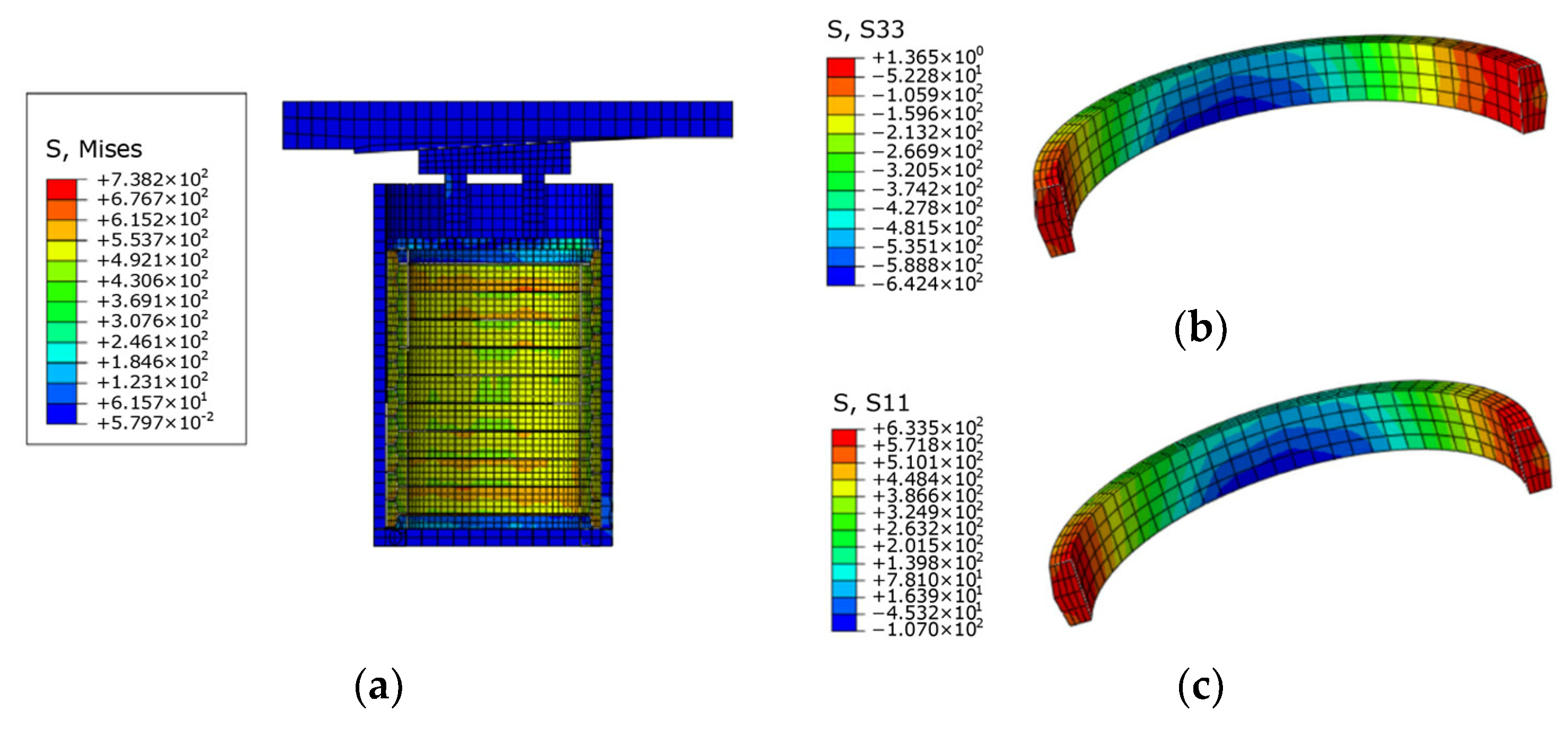
Applsci 13 07093 g022
Figure 23. Stress cloud diagram of the ring spring–friction pendulum bearing during the El Centro earthquake: (a) bearing section, (b) stress of the inner ring, and (c) stress of the outer ring.
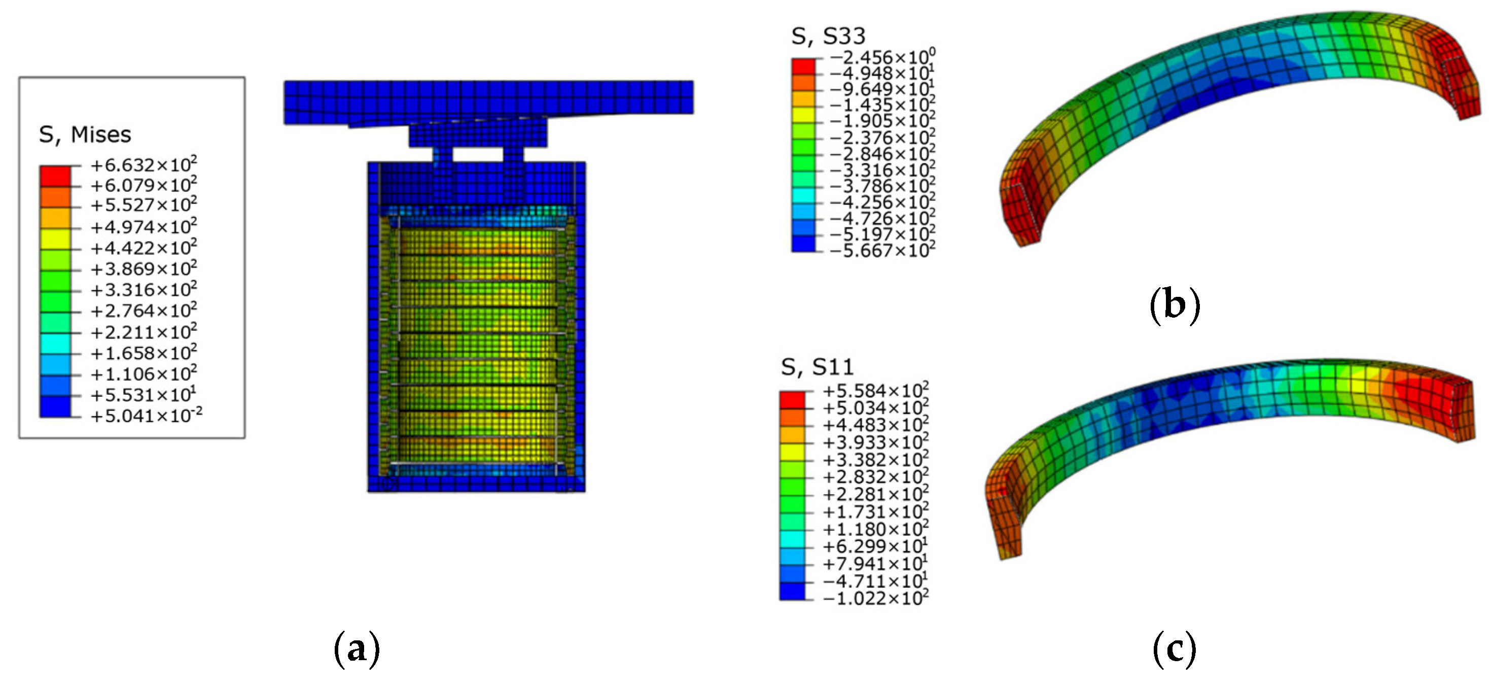
Applsci 13 07093 g023
Figure 24. Stress cloud diagram of the ring spring–friction pendulum bearing during the Kobe earthquake: (a) bearing section, (b) stress of the inner ring, and (c) stress of the outer ring.
Applsci 13 07093 g024
Table 1. Model parameters.
ModelθμKv (kN/mm)W (kN)D (mm)
a0.0413.211,200500
b0.0413.211,200500
c0.0213.211,200500
d0.026.611,200500
Table 2. Concrete and rebar material parameters.
MaterialElastic Modulus (GPa)Density
(kg/m3)
Poisson’s RatioPeak Compressive Strength (MPa)Peak Tensile Strength (MPa)
Concrete for the roof3012,7500.229.62.95
Wall and baseplate concrete3025000.229.62.95
Mid-pillars3525000.238.53.22
Rebar20078000.33240240
Table 3. Simulated loading conditions.
ConditionsArrangement of SupportsEarthquake
1Original structureEl Centro
2Original structureKobe
3Friction pendulum bearingEl Centro
4Friction pendulum bearingKobe
5Ring spring bearingEl Centro
6Ring spring bearingKobe
7Ring spring–friction pendulum bearingEl Centro
8Ring spring–friction pendulum bearingKobe
Table 4. Axial force at key parts of the structure in different conditions.
Key Cross SectionCondition 1Condition 2Condition 3Condition 4Condition 5Condition 6Condition 7Condition 8
A (106 N)7.207.232.522.7336.237.91210
B (106 N)2423.55.908.4531.232.47.878.50
C (106 N)6.146.143.694.413.193.332.342.80
D (106 N)6.166.163.714.443.263.362.412.85
Table 5. Axial force change rate of the key section in different conditions.
Key Cross SectionCondition 3Condition 4Condition 5Condition 6Condition 7Condition 8
A−65.00%−62.24%402.78%424.20%66.67%38.31%
B−75.42%−64.04%30.00%37.87%−67.21%−63.83%
C−39.90%−28.18%−48.05%−45.77%−61.89%−54.40%
D−39.77%−27.92%−47.08%−45.45%−60.88%−53.73%
Table 6. Shear force at key parts of the structure in different conditions.
Key Cross SectionCondition 1Condition 2Condition 3Condition 4Condition 5Condition 6Condition 7Condition 8
A (106 N)1.631.671.261.468.302.772.632.63
B (106 N)2.602.510.680.916.492.170.650.72
C (106 N)0.280.230.0250.0670.220.080.0290.027
D (106 N)0.250.200.0270.060.210.080.0270.027
Table 7. Shear change rate of the key section of the structure in different working conditions.
Key Cross SectionCondition 3Condition 4Condition 5Condition 6Condition 7Condition 8
A−22.34%−12.38%70.08%75.65%61.89%57.68%
B−73.85%−63.79%−16.79%−13.79%−75.13%−71.49%
C−90.84%−70.87%−73.49%−65.22%−89.40%−88.12%
D−89.61%−70.04%−72.73%−62.60%−89.61%−86.67%
Disclaimer/Publisher’s Note: The statements, opinions and data contained in all publications are solely those of the individual author(s) and contributor(s) and not of MDPI and/or the editor(s). MDPI and/or the editor(s) disclaim responsibility for any injury to people or property resulting from any ideas, methods, instructions or products referred to in the content.

