1. Introduction
The Internet of Medical Things (IoMT) is communication between medical devices, where patients wear sensor devices that sense their health parameters, such as temperature, heart rate, blood pressure, blood glucose, and respiratory activity, and then sensor devices transmit the detected health data to the health management system [
1]. In IoMT, critical patients need to be served on time. However, with the increase in medical equipment, the traditional wireless local area network no longer meets the needs of large-scale transmission, and it is difficult to guarantee quality of service (QoS) for high-priority services [
2]. Therefore, IEEE released the IEEE 802.11ax Draft, introducing multi-user media access control (MU-MAC) technology based on orthogonal frequency division multiple access (OFDMA) for improving network performance [
3]. This technique divides a complete channel into multiple orthogonal subchannels, which allows the medical emergency data of multiple patients to access the channel and transmit simultaneously. It is expected to further guarantee the QoS of critical patients. Thus, it has attracted the medical community’s attention [
4,
5].
Since critical patients are more sensitive to delay, they have a higher priority than mild patients. To guarantee QoS for critical patients, the work on QoS of high-priority users in the OFDMA protocol is studied. High-priority users obtained more transmission opportunities by assigning more subchannels to them in [
6,
7], which guaranteed their QoS. The subchannels are considered servers in [
8], and the QoS of the high-priority users is guaranteed by interrupting the service of the low-priority users if all servers are busy when the high-priority users arrive. The literature [
9] considers the heterogeneous QoS of each user and maximizes the sum rate of the system. In OFDMA protocols, the resource allocation scheme is particularly significant, which will affect the QoS of users and the performance of the whole system. If most resources are allocated to high-priority users, lower-priority users may not transmit any data in the specified time. To resolve this problem, the fairness of low-priority users is considered in [
10,
11,
12]. Throughput is maximized under fairness constraints by solving a convex optimization problem [
10]. A downlink resource scheduling scheme is proposed in [
11]. The idea is that more resources will be allocated to high-priority users, but some radio resources will be reserved for those low-priority users that will be dropped, thus guaranteeing the QoS of the low-priority users to some extent. A DRA-OFDMA protocol is proposed in [
12], which not only guarantees QoS for high-priority users but also guarantees fairness for low-priority users.
In addition, the scarcity of spectrum resources remains a concern [
13,
14]. Cognitive radio (CR) helps solve the problem of the spectrum scarcity allocated to the medical field. CR adopts dynamic spectrum access and opportunistic spectrum sharing to supply spectrum gaps to PU (who is granted spectrum access) and allows SU (who is entitled to use specific spectrum) to use the spectrum gaps unused or underused by PU [
15,
16]. SU can utilize the spectrum gap without interfering with the PU. CR has two access modes: underlay and overlay. Underlay means that SU is allowed to work over the entire frequency range, but its power needs to be limited to avoid interference with the PU [
17]. Overlay means that SU only uses the empty spectrum of PU and has no power limit [
18]. It is worth noting that a novel overlay method is proposed in [
19], in which SU does not need to sense the spectrum because SU has access opportunities in each transmission cycle, regardless of whether the PU uses the spectrum.
The integration of CR and OFDMA will further improve the utilization of spectrum resources and alleviate the shortage of spectrum resources. Recently, there has been some work to evaluate the performance of CR-OFDMA systems. In [
20,
21], the author proposed a resource allocation method in OFDMA-based CR networks to improve the throughput of CRN. A downlink resource allocation strategy for CR-OFDMA systems is proposed in [
22], which maximizes the total throughput for the CR network under the total power constraint of the cognitive base station and the interference power constraint of the PU. In [
23], the SU interference threshold is set to guarantee the QoS of PU, and the threshold is dynamically changed with the PU capacity requirement. A downlink multi-class and multi-server finite buffer queuing system is designed in [
8,
24], which guarantees QoS by limiting the number of allowed calls. However, user fairness was not considered in the above study. In [
25], the spectrum allocation and access problem are described as an optimization problem that improves the total network throughput by maximizing the total rate of all cognitive users, and the fairness analysis is made. In the case of imperfect channel sensing, the fairness of users is guaranteed by limiting the minimum and maximum number of subchannels occupied by each user [
26].
1.1. Motivation and Contribution
The work of this paper is based on the following motivations: (ⅰ) The resource allocation scheme mainly focuses on the downlink transmission and rarely focuses on the uplink, for example [
22], but the uplink transmission is more complicated. Therefore, this paper considers the uplink subchannel allocation scheme. (ⅱ) Most of the subchannel allocation schemes consider the QoS of high-priority users and the fairness of low-priority users separately, for example [
24]. Thus, the QoS of high-priority users and the fairness of low-priority users are considered in this paper. (ⅲ) Users generally need to backoff before sending data packets and need to wait for a response after sending data [
12]. However, there is no data transmission during backoff and waiting for a response, which causes a waste of spectrum resources. Therefore, in this paper, OFDMA and CR are combined to improve the utilization of feedback slots and backoff slots. Based on the above motivation, on the uplink, a new QoS-oriented and fairness-considered CR-OFDMA is proposed in the overlay mode. In this protocol scheme, a complete channel is divided into multiple orthogonal subchannels that allow multiple patients’ medical emergency data to be accessed and transmitted simultaneously. Then, QoS enhancement based on priority and fairness is achieved by improving the subchannel allocation scheme, and spectrum resource utilization is improved by making full use of the remaining subchannels, feedback slots, and backoff slots. The main contributions of this paper are as follows:
A QoS-oriented and fairness-considered CR-OFDMA is proposed in overlay mode, which improves user competition fairness, and fully utilizes the remaining subchannels, feedback slots, and backoff slots. This protocol guarantees QoS for high-priority patients and fairness for low-priority patients, reducing spectrum resource wastage. As far as we know, this is the first protocol considering QoS for high-priority patients, fairness for low-priority patients, and spectrum resource utilization.
A two-dimensional Markov model describing the protocol operation is established to analyze the protocol’s performance. The model established takes into account the conflict between users and the state of high-priority patients who fail to compete and select the remaining subchannel for transmission. Then, the transmission probability and collision probability are calculated based on the Markov chain, and expressions of the system throughput, channel utilization, and fairness index are derived.
Numerical results validate the superiority of the protocol proposed. Results show that the protocol in this paper has the best system throughput, throughput of high-priority patients, throughput of low-priority patients, and channel utilization compared to the conventional OFDMA and the DRA-OFDMA. In addition, CR-OFDMA has good fairness, which is verified.
1.2. Organization
The rest of this paper is organized as follows:
Section 2 introduces the system composition and explains the details of the protocol design.
Section 3 analyzes the system throughput and channel utilization by building a two-dimensional Markov chain model. Furthermore, fairness is analyzed.
Section 4 gives the numerical results. Finally, we conclude the paper in
Section 5.
2. System Composition and Protocol Design
This protocol is mainly intended to solve two problems in IoMT. One is to ensure the QoS of high-priority patients, the fairness of low-priority patients is often sacrificed, such as patients with chronic diseases, and patients in remote rural areas have not received attention. Another problem is the shortage of spectrum resources as medical equipment increases.
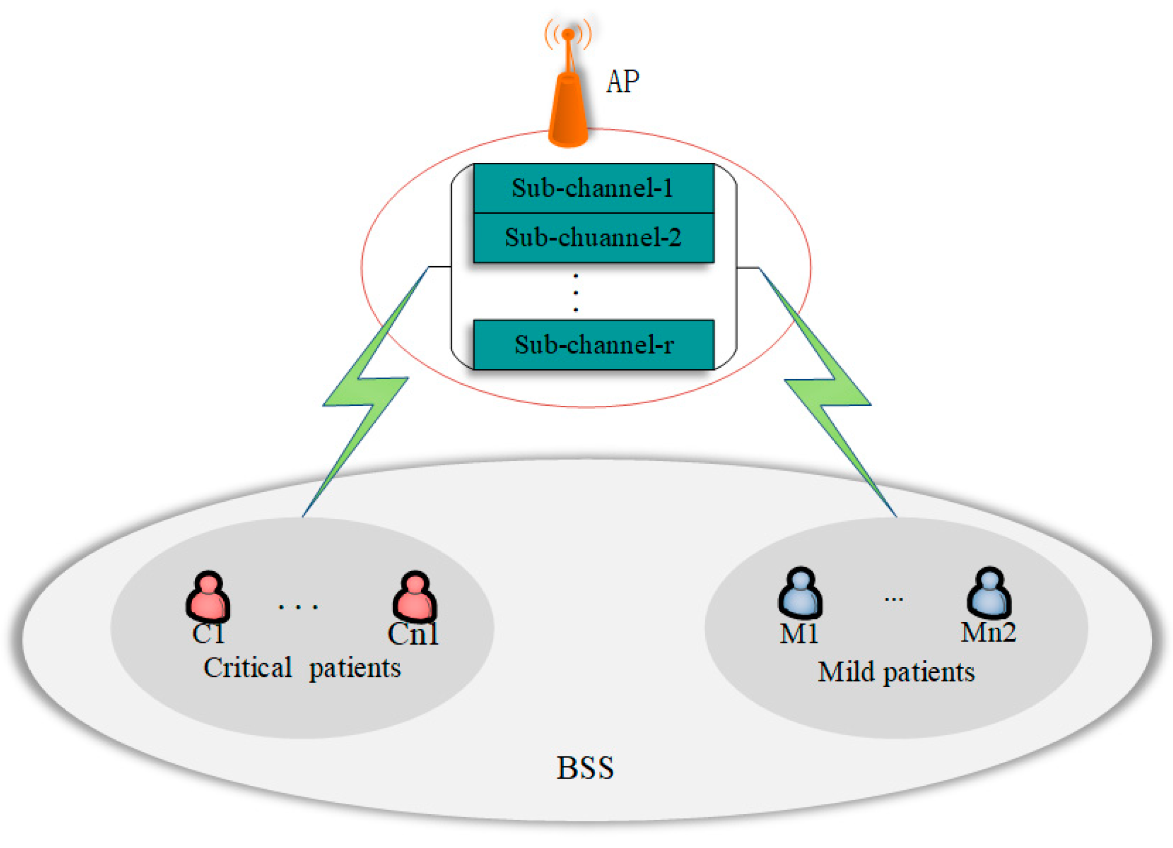
The protocol proposed in this paper is based on a single Basic Service Set (BSS) in IoMT. As shown in
Figure 1, the AP is located in the geometric center of the BSS, each patient wearing the sensor acts as an STA, and the STA distributes uniformly in the coverage area of the AP. There are
patients in total, and we divide the patients into two categories:
critical patients and
mild patients. This paper uses the OFDMA centralized partitioning method to reduce the difficulty of channel estimation, which divides the entire channel into
subchannels. Each subchannel is composed of a set of consecutive subcarriers. In addition, this is a CR network in overlay mode, so STAs have cognitive ability. Because the uplink data transmission is multi-to-one, the MAC protocol design is complicated. Therefore, this paper focuses on uplink data transmission.
The protocol in this paper is designed to guarantee both the QoS of critical patients and the fairness of mild patients and maximize spectrum resource utilization. The main idea of the protocol is shown in
Figure 2. Firstly, mild patients and critical patients compete fairly for subchannels, and then the patients who succeed in the competition transmit packets on the assigned subchannel, which guarantees the fairness of mild patients. Secondly, the critical patients who fail in competition transmit packets on the randomly chosen remaining subchannels, guaranteeing QoS for the critical patients. Finally, the critical and mild patients who succeed in the competition and the critical patients who transmit packets on the remaining subchannels are collectively named PUs, and the mild patients who fail in the competition are named SUs. The SUs transmit packets while waiting for feedback and the next round of the backoff phase of the PUs. Thus, spectrum resource utilization is improved.
The protocol is designed according to the following two parts: PU channel access and data transmission and SU channel access and data transmission.
2.1. PU Channel Access and Data Transmission
As shown in
Figure 3, we divide the channel access and data transmission process into five parts: the backoff phase, the BSR frame phase, the resource allocation phase, the PU data transmission phase, and the waiting for feedback phase.
- (I)
In the backoff phase, STAs that need to transmit packets listen to the “busy/idle” state of the channel and randomly select a number as the value of the backoff counter after the channel idles the Distributed Inter-Frame Spacing (DIFS). The value of the backoff counter is decreased by 1 for each idle slot until the value of the backoff counter is reduced to 0.
- (II)
In the BSR frame phase, when the value of the backoff counter is 0, the user can randomly select a subchannel to send a BSR frame and inform the AP that data need to be transmitted. As shown in
Figure 3, patients C1–C5 and M1–M6 have data that need to be transmitted. When the backoff is completed, these STAs randomly and independently select a subchannel to transmit the BSR frames.
- (III)
In the resource allocation phase, the AP allocates subchannels for the STAs according to the received BSR frames and informs each STA of the allocation result by sending a TF frame. To ensure fairness, as long as there is no collision and only one STA sends a BSR frame on a subchannel, the subchannel is assigned to the STA, regardless of whether the patient is critical or minor. If more than one STA in a subchannel sends BSR frames, the STA fails to compete for the subchannel. Therefore, among these r subchannels, some subchannels will not be successfully used by the STAs. To make full use of these remaining subchannels, we assign these remaining subchannels to critical patients who fail to compete, which guarantees QoS for high-priority patients.
- (IV)
In the PU data transmission phase, the critical patients and the mild patients who succeed in the competition transmit the packet on the assigned subchannel, and the critical patients who fail in the competition randomly select a remaining subchannel for packet transmission. As shown in
Figure 3, the BSR frame sent by STA C1 collides with the BSR frame sent by STA M3, but C1 is a critical patient STA, so C1 can transmit the date in a randomly chosen remaining subchannel.
- (V)
In the waiting for feedback phase, the AP sends an MBA frame to inform the STAs whether the data packets are successfully received.
2.2. SU Channel Access and Data Transmission
In the feedback phase, there is no packet transmission on the forward link when PU waits for the feedback from AP, which wastes the spectrum resources. However, in overlay mode, SU can sense this spectrum gap and use it to transmit data. Thus, let SU send packets in the feedback phase to use the spectrum resources fully. Moreover, there is also no data transmission on the channel in the next round of the backoff phase, so packets can also be sent during this period. As shown in
Figure 3, the BSR frame of SU M4 collides with the BSR frames of PU C3 and C4. Thus, data from SU M4 are transmitted during the feedback phase and the next round of the backoff phase of the PU.
Since the value of the backoff counter is chosen randomly, the backoff time is a random variable. Let
represent the backoff time. In order to not affect the transmission of the next round of BSR frames, we let the SU only transmit packets within the minimum backoff time
, and
denotes the transmission delay of the PU, where
is the number of bits of a packet,
is the transmission speed,
denotes the propagation delay, and
denotes the transmission delay of MBA frame. Therefore, the time PU waits for feedback is
and the transmission time available by the SU is
. To make it clear, the main notations used in this paper are listed in
Table 1.
Since the data to be sent for critical and mild patients are health indicators such as heartbeat and blood pressure, we assume that the packet size to be sent for critical and mild patients is identical. Let
, as shown in
Figure 4. If
, SU can complete the transmission before the next round of BSR frames is transmitted, there is no collision with the BSR frames.
If
, the packet of SU cannot be completely transmitted within
, and the transmission at the end of the SU packet will collide with the next round of BSR frames, as shown in the shaded portion of
Figure 5.
In order to avoid the collision between the SU packet and the BSR frame, the size of the SU packet needs to be reduced in the case of
, which enables SU to complete the packet transmission in
. It is necessary to equate the packet into
small packets so that the small packets can finish the transmission in
.
After the SU transmission is completed, the AP sends an MBA frame to inform whether the data packet is successfully received. Since the MBA frame is transmitted on the backward link, it does not affect the next round of BSR frames transmitted on the forward link.
2.3. Protocol Comparison
A comparison of the CR-OFDMA with the conventional OFDMA and the DRA-OFDMA is shown in
Figure 6. The right side of the figure shows the transmission process of the conventional OFDMA, and the green part is this protocol’s effective use of spectrum resources. The middle shows the transmission process of the DRA-OFDMA, and the blue part shows the efficient use of the spectrum by the DRA-OFDMA compared to the traditional OFDMA. The left shows the CR-OFDMA in this paper. The CR-OFDMA has a more efficient spectrum utilization than the DRA-OFDMA with the extra red part. Among the three protocols, the CR-OFDMA has the highest utilization of spectrum resources.
3. System Model and Performance Analysis
Assume that in a single BSS, there are
STAs (
critical patient STAs and
mild patient STAs), each STA is saturated, and the STA always has at least one packet to transmit. To transmit packets, STA needs to continuously listen to the busy/idle state of the channel, and if STA continuously listens to the channel idle with the DIFS, let the backoff counter randomly select a value to start backoff. For each idle slot, the value of the backoff counter is subtracted by one until the value of the backoff counter is reduced to 0, and then the STA can send packets. The notations in the model are summarized in
Table 2.
In order to reduce the collision, we learned the backoff mechanism from the literature [
27].
is stochastic process that presents the value of the backoff counter at time slot
, and
denotes stochastic process representing the backoff stage at time
. The pair
is used to represent the state
of each STA. The value of the backoff counter is chosen randomly from
for the STA in backoff phase
, where
denotes the size of the competition window of the
th backoff phase and
,
is the initial value of the competition window. When
, the value of the backoff counter is chosen randomly from
. The backoff phase takes the value from
, and if the packet of the STA is successfully transmitted, then the backoff phase is reduced by one; if the collision occurs, the backoff phase is increased by one.
Since high-priority STAs can transmit on the remaining subchannels after random contention failure,
is introduced to represent the state of this part of the high-priority STAs. Thus, compared with the backoff mechanism in [
27], the STA does not enter the next backoff phase directly after a collision occurs. Instead, it enters the state
(at this time, the backoff phase is still
). The STA enters the next backoff phase
if the transmission on the remaining subchannel collides again. After the STA collided into state
, if it successfully transmits on the remaining subchannel, the STA’s backoff state will change to
. If the STA successfully transmits the packet without collision, the STA’s backoff state is minus one. STA in the maximum backoff stage
enters state
after a collision and will return to the
backoff stage without plus 1 if the collision occurs again.
Assume that the probability of collision is
when critical patients with high-priority compete fairly with low-priority patients, and the probability of collision is
when the high-priority patients transmit on the remaining subchannel. We define
. The state transition diagram for the high-priority patients is given in
Figure 7.
The transition probabilities are listed as follows:
- (1)
The STA listens to the channel idle, and the value of the backoff counter is reduced by 1:
- (2)
The STA collides during fair competition, and STA enters state from state :
- (3)
The STA does not collide, and the backoff state subtracts 1:
- (4)
The STA collides on the remaining subchannel and goes from state to state :
- (5)
The STA has reached the last stage of the backoff process and remains in that state after an unsuccessful transmission on the remaining subchannel:
- (6)
The STA has no collision on the remaining subchannel and moves from state to state :
Based on the above transition probabilities, we calculated the probability of STA in state , where denotes the stationary probability of the Markov chain model.
Establishing the stationary equation according to state
, we have
. From the state
, the stationary equation is
, simplified to obtain:
Similarly, the stationary equation is established from the states
.
When
, summing Equation (9) left and right, we can obtain
. Similarly,
By eliminating
from Equation (9), we can obtain:
Substitute Equations (8) and (10) into Equation (11), we have the following:
Considering the fact that the sum of all stationary probabilities is equal to one, we can obtain:
Solving Equation (14), we have:
Thus, we obtain the transmission probability.
The probability of a collision on a subchannel can be written as [
12].
The number of high-priority STAs with a collision is
The number of remaining subchannels
is equal to the total number of subchannels minus the number of STAs that successfully competed for subchannels. We have the following:
Because the high-priority STAs directly select a remaining subchannel for packet transmission after a collision, the sending probability is 1. Therefore, the collision probability on the remaining subchannel is expressed as follows:
3.1. Throughput of PU
The probability that a subchannel is selected by at least one STA can be given as follows:
The probability that the data of the STA are transmitted successfully can be given as follows:
Thus, the throughput of the random competition phase for high- and low-priority patients is expressed as follows:
The backoff delay (
) can be defined by the following relation:
where
and
.
The average time to successfully transfer data (
) can be defined by the following relation:
where
is the time to transfer the BSR frame,
is the time for the TF frame transmission, and
is the transmission time for the MBA frame, and both are fixed values.
Substituting Equations (20), (21), and (24) into (22), the following expression is obtained:
The probability that at least one STA selects a remaining subchannel to transmit is as follows:
The probability of successful transmission on the remaining subchannel for the high-priority STA collision occurred is expressed as follows:
Then, the expression for the throughput of high-priority patients transmitted on the remaining subchannels is derived.
Thus, the throughput of PU is
, we have:
3.2. Throughput of SU
If
, the SU randomly selects a subchannel to transmit the packet, and the transmission of the SU packet does not affect the next round of BSR frames. If
, then the transmission of the SU packet will affect the next round of BSR frames, so a packet is divided into equal
copies. Thus, the number of SU is
, as follows:
The probability of collision for SU is as follows:
The probability of a subchannel being selected by at least one SU is
.
The probability of a successful transmission on the subchannel for SU is given as:
When
, the transmission can be completed within
without changing the packet size. When
, the size of the SU packet becomes
times; thus, the expression of packet size is obtained.
Then, SU throughput is expressed as follows:
Thus, the total system throughput is . We have:
3.3. Channel Utilization
The channel utilization U is the ratio of valid packets correctly received to the total packets. In this paper, the number of valid packets correctly received is the sum of the number of packets successfully transmitted when high-priority patients and low-priority patients compete fairly, the number of packets successfully sent by high-priority STA on the remaining subchannels, and the number of packets successfully transmitted by low-priority patients in the PU feedback phase and the next round of the backoff phase. Thus, the expression for channel utilization can be obtained as follows:
3.4. Fairness Analysis
This paper uses the fairness index proposed by Rajendra K. Jain to measure the fairness of low-priority users [
28]. The fairness index ranges from 0 to 1. The index close to 1 means it is very fair, and close to 0 indicates unfairness. If the system allocates resources to
users and the
th SU is assigned
, the fairness index is expressed by
.
In this paper,
equals 1. If user
successfully competes for subchannels,
equals 0 if the competition fails. Since the value of
is random, the average value of
is considered. If user
is PU,
, because PU has the opportunity to obtain the remaining subchannels. If user
is SU,
, where SU only obtains the subchannel through random competition, because SU is opportunistic to use the subchannel of other users in the backoff phase. Thus, the fairness index can be expressed as follows:
According to the above analysis, a conclusion can be drawn. will affect the fairness of the protocol. is larger; this protocol is less fair.
4. Numerical Analysis
In this section, we assume that the packet size is equal to 12,000 Bit, the maximum backoff state is 10, the minimum contention window is equal to 5, the propagation delay is 300 us, the transmission speed is 6 Mbps, a slot is 9 us, a DIFS is 34 us, a SIFS is 16 us, the transmission delay of a BSR frame is 200 us, the transmission delay of a TF frame is 400 us. The transmission delay of the MBA frame is 200 us. Then the system throughput, high-priority patient throughput, low-priority patient throughput, and channel utilization of this paper are compared with conventional OFDMA and DRA-OFDMA using MATLAB. In addition, the fairness of the protocol in this paper is illustrated.
Figure 8 shows the relationship between system throughput and the number of low-priority patients. It can be seen that as the number of low-priority patients increases, the system throughput increases and then decreases. The main reason is that the number of patients successfully accessing the subchannel and transmitting data increases when the number of low-priority patients increases, but when the number of low-priority patients is large, the collision probability becomes particularly high, resulting in a smaller number of patients successfully accessing the subchannel.
The difference between
Figure 8a,b is the number of high-priority patients. As shown in
Figure 8a, in the case of
, the DRA-OFDMA can improve the performance of traditional OFDMA and increase system throughput, but CR-OFDMA can further improve system throughput. As shown in
Figure 8b, in the case of
, the system throughput of the DRA-OFDMA is similar to the conventional OFDMA. In contrast, the system throughput of the CR-OFDMA in this paper is significantly higher than the system throughput of the traditional OFDMA and DRA-OFDMA. Thus, the CR-OFDMA in this paper offers the best throughput performance, no matter the scenario.
In
Figure 9a, we observe that as the number of low-priority patients increases, the throughput of high-priority patients decreases. The main reason is that low-priority patients occupy the subchannel, which results in a smaller number of high-priority patients accessing the subchannel. In
Figure 9b, we can see that as the number of low-priority patients increases, the throughput of low-priority patients increases and then decreases. It is due to the fact that the collision probability becomes higher when the number of low-priority patients is particularly large, resulting in a smaller successful access number of low-priority patients. In addition, from
Figure 9, we can see that the high-priority patients’ throughput of the CR-OFDMA is the same as the DRA-OFDMA and higher than the conventional OFDMA. The throughput of low-priority patients for the CR-OFDMA in this paper is higher than the DRA-OFDMA and the conventional OFDMA. As a result, the CR-OFDMA has the highest throughput performance of the three.
Figure 10 shows channel utilization versus the number of low-priority patients. As can be seen from the figure, channel utilization increases and then decreases as the number of patients increases. As the number of low-priority patients increases, the number of subchannels that can be effectively utilized increases. However, when the number of patients is particularly large, the collision probability is too high, resulting in subchannels not being utilized instead, therefore, channel utilization decreases. In addition, the CR-OFDMA has the highest channel utilization, followed by the DRA-OFDMA, and the conventional OFDMA has the lowest channel utilization, as shown in
Figure 10. The performance of the CR-OFDMA is also excellent from the perspective of channel utilization.
Figure 11 illustrates the impact of collision probability on fairness. As can be seen from the figure, the fairness index generally decreases as the collision probability increases. The reason is that the protocol designed in this paper is more advantageous to PUs in the case of high collision probability, which is to guarantee the QoS of PUs. This is evident when
is greater than 0.9. It is due to the fact that SUs hardly succeed in competing for subchannels when the collision probability is particularly large, but PUs can obtain many remaining subchannels, which is unfair. In particular, a slightly unfair phenomenon also emerges when
is near 0.4, because
reaches the maximum value when
, which is the most favorable for PUs. In addition, the fairness index decreases as the number of low-priority patients increases, which is because higher numbers of patients lead to higher collision probabilities. However, CR-OFDMA is fair because the fairness index is close to one in most conditions.
5. Conclusions
This paper proposed a QoS-oriented CR-OFDMA protocol based on CR. Firstly, high-priority and low-priority patients compete fairly for subchannels, guaranteeing the fairness of low-priority patients. Then high-priority patients who fail to compete can transmit data on the remaining subchannels, which ensures the QoS of high-priority patients. Lastly, low-priority patients who fail the competition use the feedback slots and the next round of the backoff slots of PU to transmit data, reducing the waste of channel resources. In addition, based on the proposed system, we established a two-dimensional Markov chain model and derived the expressions for throughput, channel utilization, and fairness index. Furthermore, numerical analysis is performed. An important result is that the number of users affects the system’s performance. When the number of system users is small, increasing the number of users can improve the system throughput and channel utilization, but when the number of system users is large, increasing the number of users leads to system performance degradation instead. However, the CR-OFDMA proposed in this paper outperforms conventional OFDMA and DRA-OFDMA, regardless of the number of users in the system. In addition, the CR-OFDMA has the best throughput for high-priority patients compared with the conventional OFDMA and the DRA-OFDMA. This verifies that CR-OFDMA provides good QoS for high-priority users. Another important result is that collision probability affects the fairness index. When the collision probability is particularly large, the protocol is unfair, but the CR-OFDMA protocol in this paper is relatively fair as long as the collision probability does not exceed 0.9. The system considered in this paper simply divides patients into minor and critical patients, but the patient’s condition is complex in reality. For future work, this study can be extended to multi-class user cases. In addition, combining NOMA with OFDMA will be considered to further improve spectrum efficiency.


