
Analysis of Influencing Factors and Prevention of Coal Wall Deformation and Failure of Coal Wall in Caving Face with Large Mining Height: Case Study

Abstract
:1. Introduction
2. Load-Bearing Mechanical Model
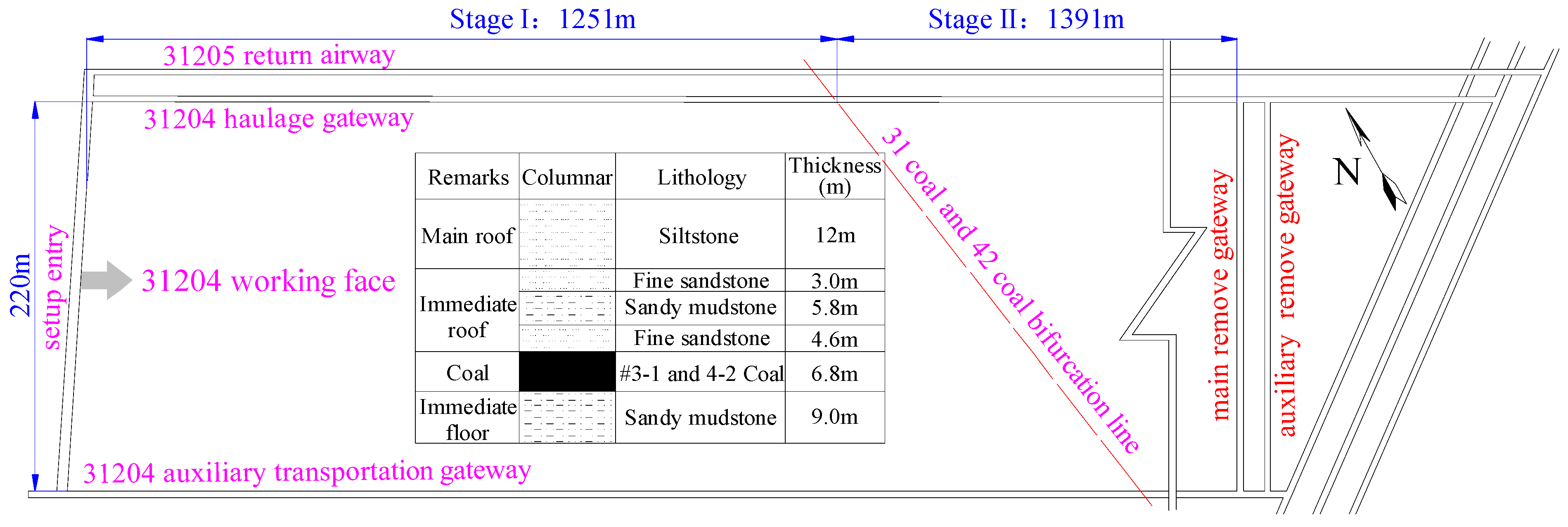
2.1. Project Profile
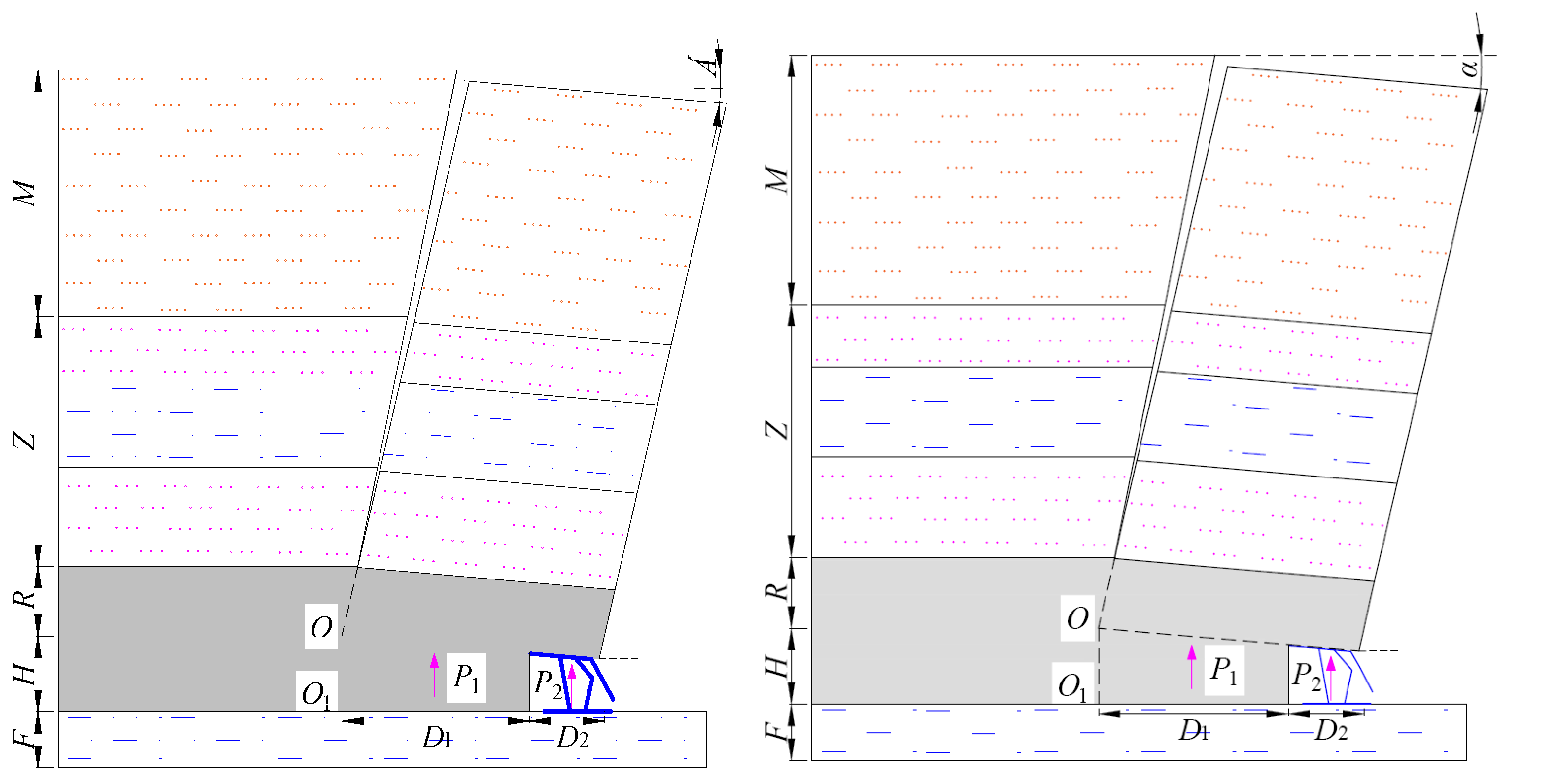
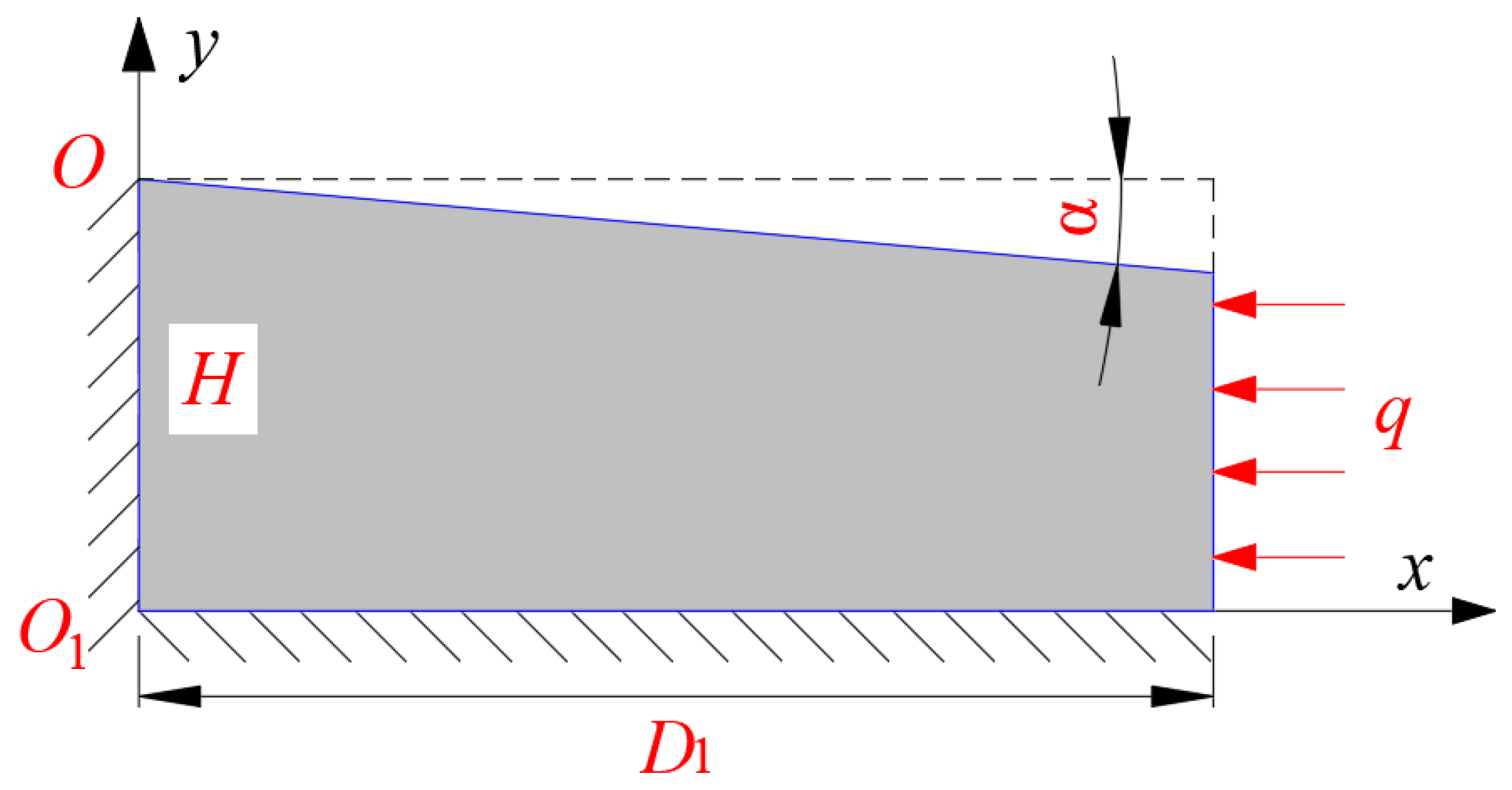
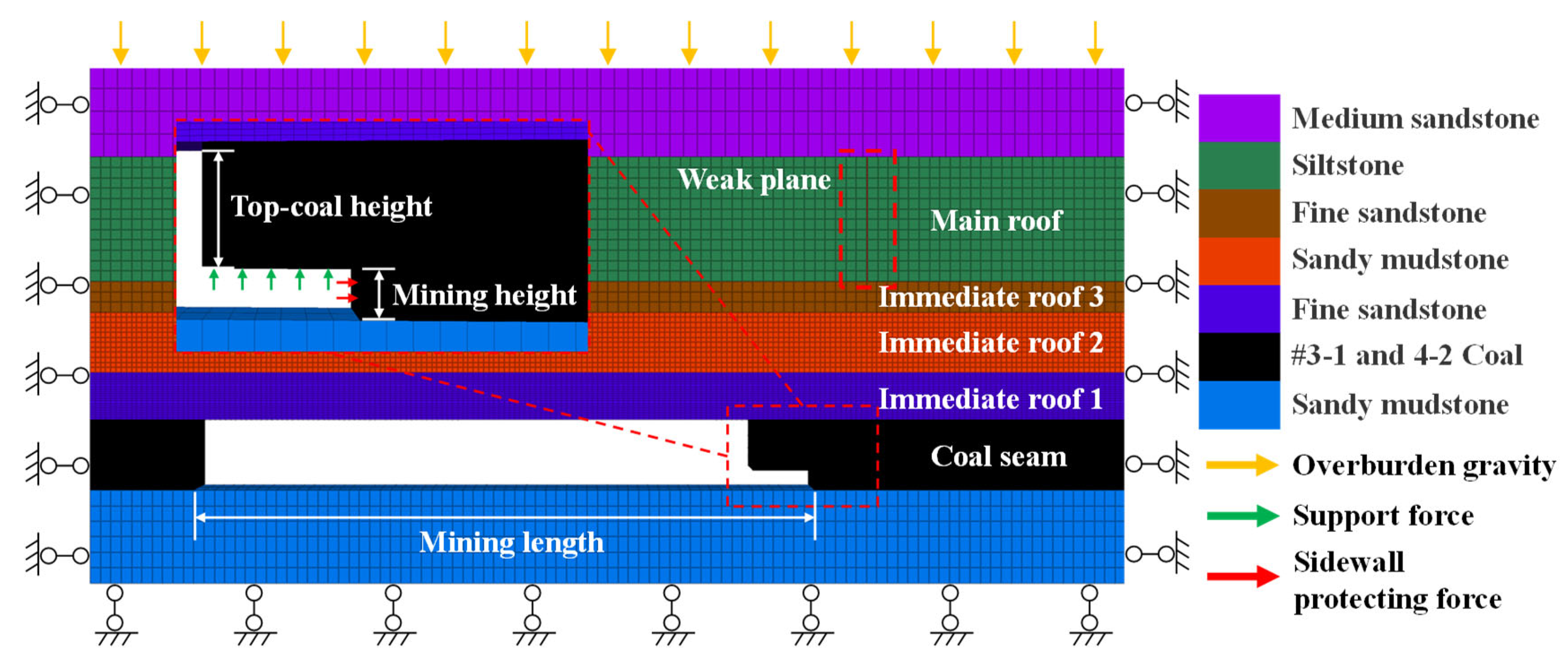
2.2. Mechanical Model
- (1)
- The components of physical force are ignored, that is, fx = 0 and fy = 0.
- (2)
- The boundary conditions of surface force are such that when x = D1, x = −q, and y = 0.
- (3)
- The displacement boundary conditions are such that when x = 0, μ = ν = 0; when y = 0, u = v = 0; when y = H, ν = −x tan α.
2.3. Analysis of Factors Influencing Failure of Coal Wall
- (1)
- Factors influencing occurrence, which refer to the natural occurrence conditions of coal seams, mainly including the thicknesses and densities of the main roof, immediate roof in each layer, and coal seams.
- (2)
- Internal influencing factors, which are the physical and mechanical properties of the coal mass, such as the elastic modulus and Poisson’s ratio. In practice, a coal mass is an elastoplastic body, so its cohesion and angle of internal friction should also be considered.
- (3)
- External influencing factors, that is, external disturbances subjected by the coal mass, such as the cutting height (or height of top coal), breaking position of the main roof, length of the top beam of the support, support strength, and sidewall-protecting force of the support.
- (1)
- Under the influences of the same factor, the characteristics of the distribution of the horizontal displacement of the coal wall along the height of the coal wall are similar; namely, the horizontal displacement is small in the upper and lower parts and large in the middle. The maximum horizontal displacement appears in the upper middle in terms of the height of the coal wall.
- (2)
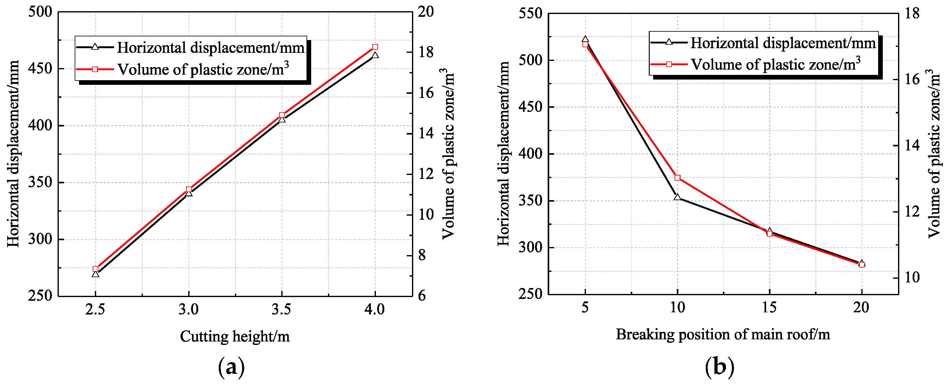
- When the cutting height is 3 m, the maximum horizontal displacement of the coal wall appears at a height of about 2 m. When the other factors remain unchanged, with the increase in the cutting height of the coal seam, the stability of the coal wall is decreased, so that the horizontal displacement of the coal wall rises. When the cutting height of the coal seam increases from 2 m to 4 m, the maximum horizontal displacement of the coal wall rises from 0.18 m to 0.35 m (Figure 6a).
- (3)
- The closer the breaking position of the main roof to the coal wall, the greater the pressure on the coal wall, leading to increased horizontal displacement. As the working face advances, the coal wall constantly approaches the breaking line of the main roof, and the horizontal displacement significantly increases, thus increasing the risk of the rib spalling of the coal wall. As shown in Figure 6b, when the distance from the breaking position of the main roof to the coal wall decreases from 25 m to 5 m, the maximum horizontal displacement of the coal wall increases from 0.08 m to 0.8 m. Moreover, with the decrease in that distance, the displacement significantly increases. When the main roof is weighted, the rib spalling of the coal wall is rapidly aggravated, which is consistent with experience.
- (4)
- As the length of top beam of the support increases, the horizontal displacement of the coal wall decreases, but the change is insignificant. As shown in Figure 6c, when the length of top beam rises from 5 m to 7 m, the maximum horizontal displacement of the coal wall decreases only by 30 mm from 0.29 m to 0.26 m. This is because, on the one hand, as the top beam of the support increases in length, the roof-control length and instability of the coal wall increase; on the other hand, the increase in the length of top beam enhances the support force, which is conducive to stabilizing the coal wall. These counteract each other, so that the change in the length of the top beam of the support has a little influence on the failure of the coal wall.
- (5)
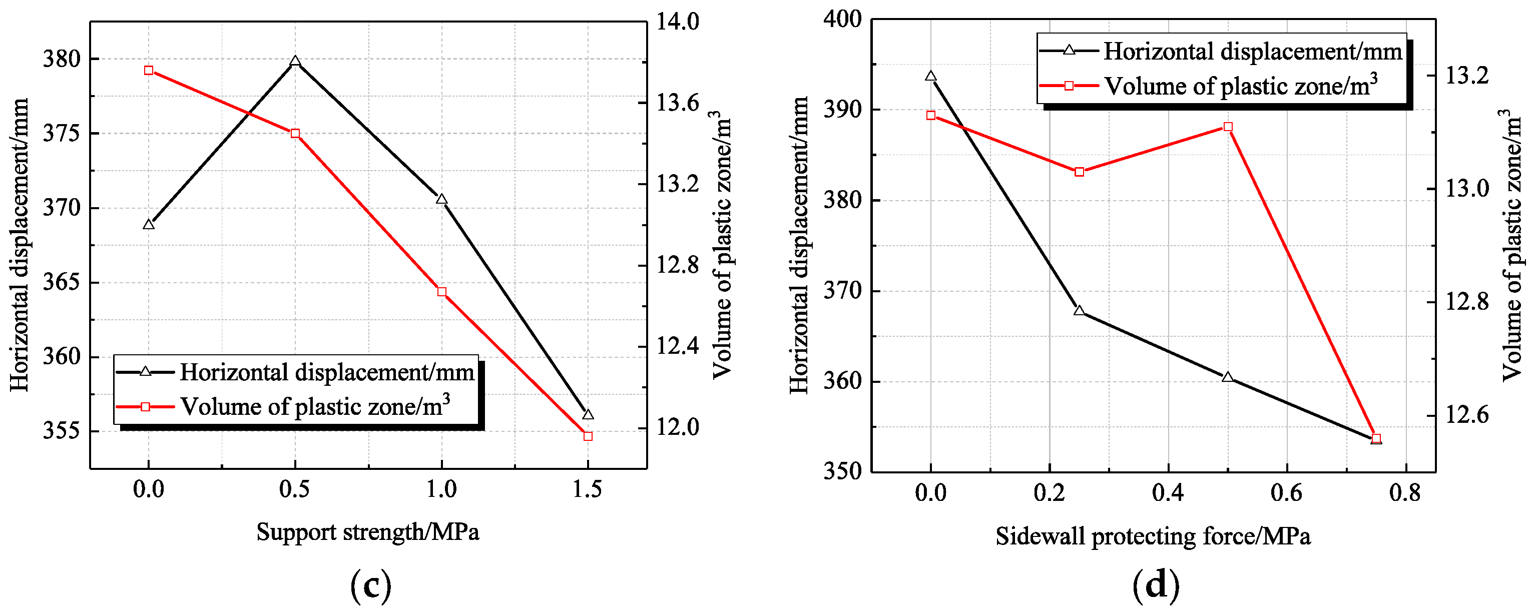
- With the increase in the support strength, the pressure of the overlying strata undertaken by the coal wall decreases, and the horizontal displacement of the coal wall reduces. As shown in Figure 6d, when the support strength is increased from 0 to 1.5 MPa, the maximum horizontal displacement decreases from 0.48 to 0.30 m. The horizontal displacement significantly decreases with increasing support strength. As the support strength is increased from 1.5 to 2.0 MPa, the maximum horizontal displacement decreases from 0.30 to 0.28 m. That is, with the further increase in the support strength, the horizontal displacement slightly reduces, indicating that 1.5 MPa is the critical support strength. Below this strength, the horizontal displacement of the coal wall is sensitive to changes in the support strength; above this strength, it is insensitive to changes in the support strength.
- (6)
- The sidewall-protecting force of the support directly acts on the coal wall and exerts an important influence on the horizontal displacement of the coal wall. With the increase in the sidewall-protecting force afforded by the support, the horizontal displacement of the coal wall decreases. As shown in Figure 6e, the maximum horizontal displacement of and the maximum displacement variation in the coal wall occur at a height of 2.0 m, which can be used as the boundary point of the influence of the sidewall-protecting force on the horizontal deformation of the coal wall. Along the height of the coal wall, the further from that point, the less sensitive the horizontal deformation of the coal wall to the sidewall-protecting force. When the support strengths are 0 and 2 MPa, at a height of 2.0 m, the horizontal displacements are 0.37 and 0.14 m (a difference of 0.23 m), respectively; at a height of 1.0 m, the horizontal displacements are 0.28 and 0.10 m (a difference of 0.18 m), respectively. This suggests that the control effects of the sidewall-protecting force on the coal wall are diminished.
3. Research Methods
3.1. Orthogonal Test Schemes
3.2. Model Establishment
4. Results
4.1. Range Analysis
- (1)
- The rank-order of the factors in terms of their influences on the horizontal displacement of the coal wall and the volume of the plastic zone differs; however, the ranges of the cutting height and the breaking position of the main roof are greater than those of the other factors, indicating that they have a greater (and more sensitive) influence on the horizontal displacement of the coal wall and the volume of the plastic zone. The support strength and sidewall-protecting force of the support are less influential. The factors were ranked in the order of the breaking position of the main roof, cutting height, sidewall-protecting force, and support strength in terms of influences on the horizontal displacement of the coal wall. The breaking position of the main roof plays a dominant role in affecting the horizontal displacement, followed by the cutting height. The factors were ranked in descending order as the cutting height, breaking position of the main roof, support strength, and sidewall-protecting force regarding their influences on the volume of the plastic zone. The cutting height plays a dominant role in affecting the volume of the plastic zone, followed by the breaking position of the main roof.
- (2)
- By affecting the thickness of the top coal and the ranges of influence of the abutment pressure, the cutting height changes the horizontal displacement of the coal wall and the volume of the plastic zone. With the increase in the cutting height, the two dependent variables are positively correlated because a larger cutting height decreases the thickness of top coal and the cushioning effects of the weak top coal, and the mine pressure directly acts on the coal wall, thus aggravating the instability of the coal wall. Furthermore, with the increase in the cutting height, the range of influence of the abutment pressure in front of the coal wall extends, so that fractures develop in the coal mass, and the range of plastic failure zone grows; therefore, the cutting height plays a leading role in affecting the volume of the plastic zone.
- (3)
- By affecting the stress in the coal wall, the breaking position of the main roof changes the horizontal displacement of the coal wall and the volume of the plastic zone. When the distance from the breaking position of the main roof to the coal wall exceeds 10 m, the two dependent variables gradually increase as the breaking position approaches the coal wall. When the distance from the breaking position to the coal wall is less than 10 m, the two dependent variables rapidly increase. By combining this with Equation (1), to ensure the stability of the structure, the force (P1) provided by the coal wall needs to increase when the breaking position of the main roof is closer to the coal wall (D1 decreases). In this case, a larger pressure applied on the coal wall leads to the extrusion of the coal wall and the constant accumulation of horizontal displacement. On this basis, it was determined that there is a certain critical value for the breaking position of the main roof. When the distance from the position to the coal wall exceeds the critical value, the stress applied to the coal wall is small, and the horizontal displacement is small, so the coal wall can remain stable. When the distance is less than the critical value, the horizontal displacement of the coal wall significantly increases, so the coal wall tends to be unstable. Therefore, the breaking position of the main roof plays a leading role in influencing the horizontal displacement.
- (4)
- The support strength and sidewall-protecting force have limited effects on the horizontal displacement of the coal wall and the volume of the plastic zone. With increasing support strength and sidewall-protecting force, the two dependent variables tend to decrease (albeit marginally). In engineering practice, the support strength and sidewall-protecting force are much less than the mine pressure, which slightly affects the dependent variables; however, because the hydraulic support directly act on the coal mining space (the sidewall-protecting force especially directly acts on the coal wall), their influences on the horizontal displacement are somewhat stronger.
4.2. Variance Analysis
- (1)
- In terms of the horizontal displacement, the breaking position of the main roof has significant effects, while the cutting height exerts a more moderate, general influence (the other factors exert insignificant effects). According to the sensitivity, the breaking position of the main roof, cutting height, sidewall-protecting force, and support strength are ranked thus (in descending order).
- (2)
- For the volume of the plastic zone, the cutting height and the breaking position of the main roof have highly significant influences, and the significance of the former is greater than that of the latter. Furthermore, the support strength has general effects, while the other factors exert insignificant influences. In accordance with their sensitivity, the cutting height, breaking position of the main roof, support strength, and sidewall-protecting force are ranked in descending order.
- (3)
- Based on the results of analysis of variance and range analysis, the factors are ranked in same order according to the sensitivity, verifying that the orthogonal test results are correct.
5. Discussion
- (1)
- The cutting height should be reasonably controlled. When considering the ratio of the cutting height to the caving height and mining speed, an appropriate cutting height should be selected. An increase in the cutting height aggravates the occurrence of mine pressure and reduces the inherent stability of the coal wall, greatly increasing the probability of the rib spalling of the coal wall. A small cutting height increases the height of coal caving and slows the advance of the working face, and an overly small cutting height does not meet the requirement for the ratio of the cutting height to the caving height. Therefore, the cutting height of the working face should be kept to below 3.5 m and should be properly reduced in the case of severe rib spalling of the coal wall.
- (2)
- The working resistance and sidewall-protecting force of the support should be improved. The selection of appropriate support equipment and processes can reduce the degree of rib spalling of the coal wall to some extent; therefore, the support parameters should be selected as follows: the support strength and sidewall-protecting strength should be 1.5 MPa and 0.75 MPa, respectively. Furthermore, considering that the #31 coal seam is independently mined in the rear section of the working face, the support height should not be too small, so a ZFY18000/25/39D two-column shield hydraulic support for coal caving should be selected.
- (3)
- The management of the coal wall should be strengthened during weighting. The breaking of the main roof significantly affects the failure of the coal wall. Therefore, coal walls are extremely prone to rib spalling and roof caving during weighting. It is necessary to standardize the operational processes and the use of equipment at the working face to ensure the requisite initial support force and working resistance. Moreover, the roof and the coal wall (after coal cutting) are quickly supported to reduce the exposure time, and the hydraulic support of roof wiping should be advanced with the appropriate pressures applied.
6. Conclusions
- (1)
- Three categories of factors influencing the failure of coal walls were determined. The factors that could be controlled by human actions are the cutting height (or height of top coal), the breaking position of the main roof, the length of top beam of the support, support strength, and the sidewall-protecting force. The changes in the horizontal displacement of the coal wall under the influences of different values of each factor were assessed.
- (2)
- The order of each factor in influencing the horizontal displacement of the coal wall and the volume of the plastic zone was determined through range analysis. The breaking position of the main roof plays a leading role in the horizontal displacement, followed by the cutting height. The cutting height plays a dominant role in affecting the volume of the plastic zone, followed by the breaking position of the main roof. The support strength and sidewall-protecting force have limited effects on the horizontal displacement of the coal wall and the volume of the plastic zone.
- (3)
- The significance of the influence of the factors on the horizontal displacement of the coal wall and the volume of the plastic zone was determined through analysis of variance. In terms of the horizontal displacement, the breaking position of the main roof has the most significant effect, while the cutting height exerts a more moderate influence. As for the volume of the plastic zone, the cutting height and breaking position of the main roof exert highly significant influences, and the significance of the cutting height is greater than that of the breaking position of the main roof (the strength of the support exerts a more moderate, general effect).
- (4)
- Technical measures, such as reasonably controlling the cutting height of the working face, increasing the working resistance and sidewall-protecting force of the support, and strengthening the management of the coal wall during weighting were proposed. The rib spalling of the coal wall in the 31,204 working face can be effectively controlled, allowing the safe, high-efficiency mining of the fully mechanized caving face over its large mining height.
Author Contributions
Funding
Institutional Review Board Statement
Informed Consent Statement
Data Availability Statement
Conflicts of Interest
References
- Pang, Y.; Wang, G.; Ren, H. Multiple influence factor sensitivity analysis on coal wall spalling of workface with large mining height. J. Min. Saf. Eng. 2019, 36, 736–745. [Google Scholar] [CrossRef]
- Wang, J.; Yu, B.; Kang, H. Key technologies and equipment for a fully mechanized top-coal caving operation with a large mining height at ultra-thick coal seams. Int. J. Coal Sci. Technol. 2015, 2, 97–161. [Google Scholar] [CrossRef] [Green Version]
- Gauna, M.; Mark, C. Unanticipated multiple seam stresses from pillar systems behaving as pseudo gob-case histories. Int. J. Min. Sci. Technol. 2017, 27, 131–137. [Google Scholar] [CrossRef]
- Li, W.; Ye, Y.; Wang, Q. Fuzzy risk prediction of roof fall and rib spalling: Based on FFTA-DFCE and risk matrix methods. Environ. Sci. Pollut. Res. 2020, 27, 8535–8547. [Google Scholar] [CrossRef]
- Mohamed, K.; Dyke, M.V.; Rashed, G.; Sears, M.M.; Kimutis, R. Preliminary rib support requirements for solid coal ribs using a coal pillar rib rating (CPRR). Int. J. Min. Sci. Technol. 2021, 31, 15–22. [Google Scholar] [CrossRef]
- Bai, Q.; Tu, S.; Li, Z. Theoretical analysis on the deformation characteristics of coal wall in a longwall top coal caving face. Int. J. Min. Sci. Technol. 2015, 25, 199–204. [Google Scholar] [CrossRef]
- Kong, D.; Xiong, Y.; Cheng, Z.; Wang, N.; Wu, G.; Liu, Y. Stability analysis of coal face based on coal face-support-roof system in steeply inclined coal seam. Geomech. Eng. 2021, 25, 233–243. [Google Scholar] [CrossRef]
- Yang, H.; Liu, Y.; Cao, S.; Pan, R.; Wang, H.; Li, Y.; Luo, F. A caving self-stabilization bearing structure of advancing cutting roof for gob-side entry retaining with hard roof stratum. Geomech. Eng. 2020, 21, 23–33. [Google Scholar] [CrossRef]
- Yuan, Y.; Tu, S.; Wu, Q. Mechanics of rib spalling of high coal walls under fully-mechanized mining. Min. Sci. Technol. 2011, 21, 129–133. [Google Scholar] [CrossRef]
- Aleksandrov, V.M.; Pozharskii, D.A. Three-dimensional contact problems with friction for a composite elastic wedge. J. Appl. Math. Mech. 2010, 74, 692–698. [Google Scholar] [CrossRef]
- Liu, S.; Yang, K.; Zhang, T. Rib spalling 3D model for soft coal seam faces with large mining height in protective seam mining. Geofluids 2020, 2020, 8828844. [Google Scholar] [CrossRef]
- Yang, P.; Liu, C.; Wu, F. Breakage and falling of a high coal wall in a thick mined seam. J. China Univ. Min. Technol. 2012, 41, 371–377. [Google Scholar]
- Erzin, Y.; Cetin, T. The prediction of the critical factor of safety of homogeneous finite slopes subjected to earthquake forces using neural networks and multiple regressions. Geomech. Eng. 2014, 6, 305–313. [Google Scholar] [CrossRef]
- Li, X.; Kang, T.; Yang, Y. Analysis of coal wall slip risk and caving depth based on Bishop method. J. China Coal Soc. 2015, 40, 1498–1504. [Google Scholar] [CrossRef]
- Wu, Y.; Lang, D.; Xie, P. Mechanism of disaster due to rib spalling at fully-mechanized top coal caving face in soft steeply dipping seam. J. China Coal Soc. 2016, 41, 1878–1884. [Google Scholar] [CrossRef]
- Pang, Y.; Wang, G. Hydraulic support protecting board analysis based on rib spalling ‘tensile cracking-sliding’ mechanical model. J. China Coal Soc. 2017, 42, 1941–1950. [Google Scholar] [CrossRef]
- Sinha, S.; Walton, G. Modeling behaviors of a coal pillar rib using the progressive S-shaped yield criterion. J. Rock Mech. Geotech. 2020, 12, 484–492. [Google Scholar] [CrossRef]
- Guo, W.; Liu, C.; Dong, G. Analytical study to estimate rib spalling extent and support requirements in thick seam mining. Arabian J. Geosci. 2019, 12, 1–11. [Google Scholar] [CrossRef]
- Lei, W.; Li, X.; Du, W. Research on mechanism and prevention technology of rib spalling in fully-mechanized coal mining face with soft and unstable seam. In IOP Conference Series Earth and Environmental Science; IOP Publishing: Bristol, UK, 2019; Volume 252, p. 052065. [Google Scholar] [CrossRef]
- Wang, K.; Zhao, T.; Yetilmezsoy, K. Cutting-caving ratio optimization of fully mechanized caving mining with large mining height of extremely thick coal seam. Adv. Civ. Eng. 2019, 2019, 7246841. [Google Scholar] [CrossRef]
- Zhang, Y.; Liu, J.; Pang, Y. Effect analysis of prevention rib spalling system in hydraulic support. J. China Coal Soc. 2011, 36, 691–695. [Google Scholar] [CrossRef]
- Ghadimi, M.; Shahriar, K.; Jalalifar, H. A new analytical solution for the displacement of fully grouted rock bolt in rock joints and experimental and numerical verifications. Tunn. Undergr. Space Technol. 2015, 50, 143–151. [Google Scholar] [CrossRef]
- Yang, S.; Kong, D.; Yang, J. Coal wall stability and grouting reinforcement technique in fully mechanized caving face during topple mining. J. Min. Saf. Eng. 2015, 32, 827–833+839. [Google Scholar] [CrossRef]
- Mohamed, K.M.; Murphy, M.M.; Lawson, H.E.; Klemetti, T. Analysis of the current rib support practices and techniques in U.S. coal mines. Int. J. Min. Sci. Technol. 2016, 26, 77–87. [Google Scholar] [CrossRef] [PubMed] [Green Version]
- Erzin, Y.; Gul, T.O. The use of neural networks for the prediction of the settlement of pad footings on cohesionless soils based on standard penetration test. Geomech. Eng. 2013, 5, 541–564. [Google Scholar] [CrossRef]
- Liu, S.; Li, Z.; Li, Y. Strength properties of Bayer red mud stabilized by lime-fly ash using orthogonal experiments. Constr. Build. Mater. 2018, 166, 554–563. [Google Scholar] [CrossRef]
- Li, X.; Ju, M.; Yao, Q. Numerical investigation of the effect of the location of critical rock block fracture on crack evolution in a gob-side filling wall. Rock Mech. Rock Eng. 2015, 49, 1041–1058. [Google Scholar] [CrossRef]
- Rashed, G.; Mohamed, K.; Kimutis, R. A coal rib monitoring study in a room-and-pillar retreat mine. Int. J. Min. Sci. Technol. 2021, 31, 127–135. [Google Scholar] [CrossRef]
- Wu, X.; Leung, D.Y.C. Optimization of biodiesel production from camelina oil using orthogonal experiment. Appl. Energy 2011, 88, 3615–3624. [Google Scholar] [CrossRef]
- Yuan, Z.; Chen, X.; Zeng, H.; Wang, K.; Qiu, J. Identification of the elastic constant values for numerical simulation of high velocity impact on dyneema® woven fabrics using orthogonal experiments. Compos. Struct. 2018, 204, 178–191. [Google Scholar] [CrossRef] [Green Version]
- Liu, S.; Li, X.; Wang, D. Mechanical and acoustic emission characteristics of coal at temperature impact. Nat. Resour. Res. 2019, 29, 1755–1772. [Google Scholar] [CrossRef]
- Gullu, H.; Fedakar, H.I. On the prediction of unconfined compressive strength of silty soil stabilized with bottom ash, jute and steel fibers via artificial intelligence. Geomech. Eng. 2017, 12, 441–464. [Google Scholar] [CrossRef]
- Yu, X.; Chen, X. Variational laws of debris flow impact force on the check dam surface based on orthogonal experiment design. Geotech. Geol. Eng. 2017, 35, 2511–2522. [Google Scholar] [CrossRef]
- Zhong, D.; Chu, Z.; Ren, B. Global comprehensive sensitivity analysis of arch dam construction parameters based on orthogonal experiment. Trans. Tianjin Univ. 2017, 23, 427–433. [Google Scholar] [CrossRef]


| Level | Factor | |||
|---|---|---|---|---|
| Cutting Height/m | Breaking Position of Main Roof/m | Support Strength/MPa | Sidewall Protecting Force/MPa | |
| 1 | 2.5 | 5 | 0 | 0 |
| 2 | 3.0 | 10 | 0.5 | 0.25 |
| 3 | 3.5 | 15 | 1.0 | 0.5 |
| 4 | 4.0 | 20 | 1.5 | 0.75 |
| Test Serial Number | Cutting Height/m | Breaking Position of Main Roof/m | Support Strength/MPa | Sidewall Protecting Force/MPa | Horizontal Displacement/mm | Volume of Plastic Zone/m3 |
|---|---|---|---|---|---|---|
| i-1 | 2.5 | 5 | 0 | 0 | 423.61 | 12.25 |
| i-2 | 2.5 | 10 | 1 | 0.25 | 275.15 | 7 |
| i-3 | 2.5 | 15 | 1.5 | 0.5 | 201.73 | 5.13 |
| i-4 | 2.5 | 20 | 0.5 | 0.75 | 175.97 | 5.06 |
| i-5 | 3.0 | 5 | 0.5 | 0.25 | 508.27 | 16.17 |
| i-6 | 3.0 | 10 | 1.5 | 0 | 333.38 | 10.69 |
| i-7 | 3.0 | 15 | 1 | 0.75 | 251.41 | 8.79 |
| i-8 | 3.0 | 20 | 0 | 0.5 | 266.78 | 9.44 |
| i-9 | 3.5 | 5 | 1 | 0.5 | 548.12 | 19.06 |
| i-10 | 3.5 | 10 | 0 | 0.75 | 379.37 | 15.63 |
| i-11 | 3.5 | 15 | 0.5 | 0 | 410.02 | 13.75 |
| i-12 | 3.5 | 20 | 1.5 | 0.25 | 281.92 | 11.25 |
| i-13 | 4.0 | 5 | 1.5 | 0.75 | 607.17 | 20.75 |
| i-14 | 4.0 | 10 | 0.5 | 0.5 | 425.01 | 18.81 |
| i-15 | 4.0 | 15 | 0 | 0.25 | 405.5 | 17.70 |
| i-16 | 4.0 | 20 | 1 | 0 | 407.44 | 15.83 |
| Index | Factor | Rank of Influence Level | |||||
|---|---|---|---|---|---|---|---|
| Horizontal displacement | Cutting height | 269.12 | 339.96 | 404.86 | 461.28 | 192.17 |
|
| Breaking position of main roof | 521.79 | 353.23 | 317.17 | 283.03 | 238.77 | ||
| Support strength | 368.82 | 379.82 | 370.53 | 356.05 | 23.77 | ||
| Sidewall protecting force | 393.61 | 367.71 | 360.41 | 353.48 | 40.13 | ||
| Volume of plastic zone | Cutting height | 7.36 | 11.27 | 14.92 | 18.27 | 10.91 |
|
| Breaking position of main roof | 17.06 | 13.03 | 11.34 | 10.40 | 6.66 | ||
| Support strength | 13.76 | 13.45 | 12.67 | 11.96 | 1.8 | ||
| Sidewall protecting force | 13.13 | 13.03 | 13.11 | 12.56 | 0.57 |
| Serial Number | Range of F | Sensitivity Statement | Degree |
|---|---|---|---|
| 1 | F > F0.001(ff, fe) | Highly significant effects | *** |
| 2 | F0.001(ff, fe) > F > F0.01(ff, fe) | Significant effects | ** |
| 3 | F0.01(ff, fe) > F > F0.05(ff, fe) | General effects | * |
| 4 | F < F0.05(ff, fe) | Insignificant effects |
| Index | Source Variance | Sum of the Squared Deviation | Degrees of Freedom | F | Significance |
|---|---|---|---|---|---|
| Horizontal displacement | Cutting height | 82,486.15 | 3 | 20.17 | * |
| Breaking position of main roof | 134,689.21 | 3 | 32.94 | ** | |
| Support strength | 1147.76 | 3 | 0.28 | ||
| Sidewall-protecting force | 3687.77 | 3 | 0.90 | ||
| Volume of plastic zone | Cutting height | 265.15 | 3 | 400.07 | *** |
| Breaking position of main roof | 103.96 | 3 | 156.85 | *** | |
| Support strength | 7.87 | 3 | 11.88 | * | |
| Sidewall-protecting force | 0.87 | 3 | 1.30 |
Disclaimer/Publisher’s Note: The statements, opinions and data contained in all publications are solely those of the individual author(s) and contributor(s) and not of MDPI and/or the editor(s). MDPI and/or the editor(s) disclaim responsibility for any injury to people or property resulting from any ideas, methods, instructions or products referred to in the content. |
© 2023 by the authors. Licensee MDPI, Basel, Switzerland. This article is an open access article distributed under the terms and conditions of the Creative Commons Attribution (CC BY) license (https://creativecommons.org/licenses/by/4.0/).
Share and Cite
Meng, G.; Zhang, J.; Wang, C.; Zhou, N.; Li, M. Analysis of Influencing Factors and Prevention of Coal Wall Deformation and Failure of Coal Wall in Caving Face with Large Mining Height: Case Study. Appl. Sci. 2023, 13, 7173. https://doi.org/10.3390/app13127173
Meng G, Zhang J, Wang C, Zhou N, Li M. Analysis of Influencing Factors and Prevention of Coal Wall Deformation and Failure of Coal Wall in Caving Face with Large Mining Height: Case Study. Applied Sciences. 2023; 13(12):7173. https://doi.org/10.3390/app13127173
Chicago/Turabian StyleMeng, Guohao, Jixiong Zhang, Chongjing Wang, Nan Zhou, and Meng Li. 2023. "Analysis of Influencing Factors and Prevention of Coal Wall Deformation and Failure of Coal Wall in Caving Face with Large Mining Height: Case Study" Applied Sciences 13, no. 12: 7173. https://doi.org/10.3390/app13127173