Article

Research on the High Speed of Piston Pumps Based on Rapid Erecting of Launch Vehicles

School of Aerospace Engineering, Beijing Institute of Technology, Beijing 100081, China
*
Author to whom correspondence should be addressed.
Appl. Sci. 2023, 13(12), 7178; https://doi.org/10.3390/app13127178
Submission received: 15 April 2023 / Revised: 9 June 2023 / Accepted: 13 June 2023 / Published: 15 June 2023
(This article belongs to the Section Mechanical Engineering)

Abstract

:
Rapid erection is a key technology for modern warfare in vehicle weapon launch systems. It is challenging to attain rapidity with the hydraulic erecting system because of the intensified cavitation in the piston chamber at high speeds, which reduces volumetric efficiency and increases flow pulsation in the typical high-pressure axial piston pump. In this paper, an improved scheme for the cylinder window area overflow surface was proposed to solve this problem. Based on the full cavitation model and the compressible model, a numerical model of the internal flow in the piston pump was developed, and the effect of rotational speeds on the flow and cavitation characteristics of the pump was analysed. The results show that after the improvement, the maximum flow of the pump is increased from 1.765 kg/s to 2.295 kg/s, an increase of 30.028%, and the maximum speed corresponding to the volumetric efficiency of more than 90% is increased from 1500 rpm to 2100 rpm. At high speeds, the improved block can effectively suppress the cavitation and backflow in the piston chamber, improve the volumetric efficiency of the piston pump and reduce the flow pulsation, which is conducive to reducing the vibration and noise of the pump body.

1. Introduction

Modern warfare is fast-paced and high-intensity, and mobile launch faces the threat of all-around reconnaissance and long-range precision strikes. Therefore, preparation time before missile launch must be minimised [1]. Rapid erection, a phase in preparation for missile weapon launch [2], has become an important research direction to improve the launch system’s rapid response ability and manoeuvrability, which is crucial for enhancing the mobile weapon combat system’s survivability.
Hydraulic systems have been commonly employed in missile erecting devices due to their excellent stability and reliability [3]. Figure 1 depicts the conventional missile erection scheme. The high-pressure axial piston pump drives hydraulic oil into the hydraulic cylinder via the hydraulic system, pushing the hydraulic rods out and completing the erection [4]. Improving the erection drive source is the most important approach for achieving a rapid erection. Some innovative erection drive schemes, such as electric cylinder drive [2], gas-liquid mixed drive [5,6], gas drive [7,8], etc., have been proposed. The above methods, however, are still in the theoretical stage, and their reliability has not been evaluated by a huge number of engineering practices. Because the hydraulic system has advantages from established technology and good reliability, research on the rapid hydraulic erection system is still very important.
The high-pressure axial piston pump has the benefits of high efficiency, a simple structure and high power density as the power source of the hydraulic erection system. In general, output flow stability, power density, volumetric efficiency, vibration and noise are employed as the primary performance indicators. The high-pressure axial piston pump’s bearing capacity and flow rate directly affect the speed of missile erection. Currently, it is challenging to install a large displacement axial piston pump as a power source in a hydraulic system due to the limited space of launch vehicles [9]. It is necessary to increase the rotational speed of piston pumps in order to achieve rapid erection. However, high-speeding increases cavitation in the piston chamber [10,11,12,13], slows the filling rate of piston pumps [14] and lowers volumetric efficiency. This causes the flow rate to increase slowly or even drop when rotational speed is increased. Cavitation will also aggravate flow pulsation and increase the vibration and noise of the system, which is detrimental to the hydraulic system’s stability. At the same time, the backflow will happen when the piston chamber and suction and discharge oil unloading groove of the valve plate come into contact. Backflow will not only cause cavitation and damage the wall, but it will also increase flow pulsation, which is not conducive to the efficient and steady working of the system.
In order to improve volumetric efficiency and reduce flow pulsation, the cavitation phenomenon in the piston pump must be suppressed [15,16]. In an axial piston pump, there are two types of cavitation: (1) Vaporous cavitation: When the pressure of hydraulic oil falls below the saturated vapour pressure, the medium gasifies. (2) Gaseous cavitation: When the pressure is lower than the air separation pressure, the dissolved air precipitates from the oil, and there is no phase change. When vapour bubbles collapse, they not only reduce volumetric efficiency but also hit the inner wall of the pump, exacerbating the pump’s vibration and noise. Although the gaseous bubbles have no effect on the pump body when they collapse, it is the primary cause of volumetric efficiency reduction. Nowadays, the main measures to prevent the cavitation of piston pumps include installing booster pumps at the oil suction port [17] or booster impellers to increase the inlet pressure [18]; lowering the inclination angle of the swash plate [19]; using capped pistons [20]; optimising the size [21], shape and the number of unloading grooves [22,23,24,25]; topology optimisation of the suction duct [26]; using inward or outward inclined cylinder waist bores to allow oil to be drawn in by the centrifugal force generated [27]; optimising the structural parameters of the waist-shaped bore in the window area of the cylinder [28]. However, the adoption of booster pumps or booster impellers will increase the size of the hydraulic erection system, which is incompatible with the limited space of the launch vehicle. Although the cavitation of piston chambers can be suppressed by reducing the swash plate angle, the theoretical flow will be reduced.
In summary, there are several studies on the cavitation of piston pumps and cavitation suppression. One of the key directions of research is to optimise the waist-shaped bore of the cylinder to suppress cavitation. Previous studies have only focused on the improvement of the inclined waist hole and the optimisation of the structural parameters of the waist hole cross-flow surface [27,28]. However, there are few publications on the suppression of cavitation and enhancement of piston chamber volumetric efficiency by improving the overflow surface in the window area of the cylinder at high speeds. As a result, it is vital to study the high-speed design and cavitation suppression of a high-pressure axial piston pump from the perspective of the design of the overflow surface in the window area of the cylinder.
This study aims to explore an approach for enhancing the volumetric efficiency and reducing the flow pulsation of piston pumps at high rotational speeds. First, a numerical model of the piston pump’s internal flow with cavitation was developed. Second, an improved scheme for the cylinder window area, which is used to suppress cavitation in the piston chamber, increase volumetric efficiency and improve effective speed, was proposed. Third, the flow characteristics of the traditional and improved cylinders were compared. The cause of why the improved cylinder can enhance effective rotational speed was analysed from the perspectives of suppression of cavitation and backflow.

2. Methodology

2.1. Erection Dynamics Model

The rapid erection of missiles is divided into three stages.
(1)
Before erection, the missile is placed on the frame at a horizontal or slight inclination angle and is restrained by various means to ensure the safety of the transportation process and prevent the missile from fleeing forward or tumbling horizontally in the case of braking deceleration and sharp turning.
(2)
During erection, the hydraulic system is injected with oil by a high-pressure axial piston pump. The piston rods of the multi-stage hydraulic cylinder are forced to lengthen sequentially, causing the missile to spin around the bottom hinge with a specific motion law and gradually transition to a vertical state.
(3)
After erection, the missile is in a vertical state. The travel switch is triggered, the control system issues a stop command, the hydraulic cylinder is locked, and the launch procedure can be carried out.
As shown in Figure 2, the missile is subjected to the combined action of gravity. G x ,   y , hydraulic cylinder support force F , and the constraint force of each hinge point at time t during the erection, ignoring the friction force of the hydraulic rod when it is extended. The pivot point O is located at the junction of the launcher’s tail and the frame. The point O 1 is the rotating centre of the erecting cylinder around the hinge position in the middle of the frame. The point O 2 is the rotating centre of the erecting cylinder around the launcher.
The vertical distance between point O and point O 1 is L 3 . O O 1 = L 1 , O O 2 = L 2 and O 1 O 2 = L t increase with time. The movement law of missile erecting is indicated by the change in erecting angle θ ( t ) = O 2 O x . The force arm of the hydraulic cylinder support force F relative to the rotating centre point O is:
l = L 2 sin ( 180 ° O 1 O 2 O )
In Δ O O 1 O 2 , and L 2 are constants. According to the sine theorem, we can get:
L 1 sin O 1 O 2 O = L ( t ) sin ( θ 0 + θ ( t ) ) = L 2 sin ( O 2 O 1 O )
According to the cosine theorem, it can be obtained:
L ( t ) 2 = L 1 2 + L 2 2 2 L 1 L 2 cos ( θ 0 + θ ( t ) ) L 1 M J
The expression of force arm l can be simplified as:
l = L 1 L 2 sin ( θ 0 + θ ( t ) ) L ( t )
The moment of the erection mechanism about the centre of rotation O , according to the moment of moment theorem, consists of the moment of weight M G , the moment of inertia M J and the moment T provided by the hydraulic cylinder:
T = M G + M J
M G = G x 2 + y 2 cos ( ψ + θ ( t ) )
M J = J θ ¨ ( t )
where J is the rotational inertia of the missile with point O as the rotation centre. By combining Equations (5)–(7), the hydraulic cylinder support force F can be obtained:
F = G x 2 + y 2 cos ( ψ + θ ( t ) ) + J θ ¨ ( t ) L 1 L 2 sin ( θ 0 + θ ( t ) ) L ( t )
To solve the hydraulic cylinder support force, combine Equations (3) and (8) and add the hydraulic cylinder expansion length curve L t . Missiles are typically built in a 150-second uniform acceleration-uniform speed-uniform deceleration sequence. In order to satisfy the needs of modern warfare’s quickness, the L t curve is given to acquire the hydraulic bearing capacity F during the erection process based on the completion of the erection action in 30 s. (The hydraulic bearing capacity F and the hydraulic cylinder support force F are a pair of interaction forces). Figure 3 depicts the specific results. The hydraulic bearing capacity increases first and subsequently declines as the erecting angle increases. Because the missile erects too quickly, the hydraulic bearing capacity is negative before the erection is completed. This means that the hydraulic cylinder must produce tension to draw the missile smoothly to the launch position.
According to the dynamic model shown above, the maximum hydraulic bearing capacity is 292.63 KN . Assuming that the oil may freely move through the hydraulic components, such as the reversing valve, the pressure at the axial piston pump’s oil outlet is around 25 MPa . The high-speed flow characteristics of the axial piston pump are then studied based on the above conditions.

2.2. Axial Piston Pump Model

The major functioning parts of an axial piston pump include a swash plate, cylinder block, piston, valve plate and spindle. Due to the effect of the fixed swash plate, the piston rotates with the cylinder body and conducts periodic reciprocating motion in the cylinder body. The volume of the sealing chamber composed of each piston and the cylinder body changes with time, and oil absorption and drainage are accomplished via the oil suction and discharge ports of the valve plate. Figure 4 depicts the operation of the piston pump.
The instantaneous flow Q of a piston chamber is:
Q i = π r 2 w R 0 tan ( β ) sin ( w t + i × 2 π / z )
where w is the rotational speed of the piston chamber around the axis, R 0 is the radius of the distribution circle of the piston chamber, β is the inclination angle of the swashplate of the axial piston pump, z is the number of piston chambers, t is time and r is the radius of the piston chamber. Assuming that at a certain time, the number of piston chambers in the oil discharge stage is m , the theoretical flow of the axial piston pump Q t is [29]:
Q t = i m Q i = π r 2 w R 0 tan ( β ) i m sin ( w t + i × 2 π / z )
The above calculations of theoretical flow do not take cavitation into account, but in practice, cavitation occurs in the hydraulic oil in axial piston pumps.
The full cavitation model includes the vapour equation, the free gas equation and the dissolved gas equation, where the vapour equation represents vaporous cavitation and the free gas equation and dissolved gas equation represent gaseous cavitation. This allows the model to accurately simulate cavitation phenomena in hydraulic machinery [30,31].
The vapour equilibrium equation is:
t Ω ( t ) ρ f v d Ω + σ ρ ( ( v v σ ) n ) f v d σ = σ ( D f + μ t σ f ) ( f v n ) d σ + Ω ( R e R c ) d Ω
The vapour generation rate R e and the vapour dissipation rate R c are given by:
R e = C e ρ l ρ v 2 3 P P v / ρ l 1 / 2 ( 1 f v g f )
R c = C c ρ l ρ v 2 3 p p v / ρ l 1 / 2 f v
The equilibrium equations for the free gas and dissolved gas are, respectively:
t Ω ρ g f d Ω + σ ρ ( ( v v σ ) n ) g f d σ = σ ( D g + μ t σ f ) ( g f n ) d σ + Ω ( ρ ( g d g dequil ) τ ) d Ω
t Ω ρ g d d Ω + σ ρ ( ( v v σ ) n ) g d d σ = σ ( D g d + μ t σ t ) ( g d n ) d σ Ω ( ρ ( g d g dequil ) τ ) d Ω
g dequil = P P gdequilref g dequilref
In the above equations, D f is the vapour diffusion coefficient, D g is the free gas diffusion coefficient, D gd is the dissolved gas diffusion coefficient, C c is the cavitation condensation coefficient and C e is the cavitation evaporation coefficient. As cavitation in axial piston pumps occurs in the high-speed flow region, C c is 0.01 and C e is 0.02 [30]. Further, f v is the vapour mass fraction, g d is the dissolved gas mass fraction, g dequil is the dissolved gas equilibrium mass fraction, g dequilref is the dissolved gas equilibrium mass fraction under relative pressure, g f is the free gas mass fraction, p is the oil pressure, p v is the oil saturated vapour pressure, p gdequilref is the dissolved gas mass fraction relative pressure and t is the time. Likewise, Ω is the control volume, σ is the control surface area, σ t is the turbulent Schmidt number, µ t is the turbulent viscosity and τ is the dissolved gas dissipation time.
The fluid domain of an axial piston pump is separated into five blocks: suction port, discharge port, valve plate suction port, valve plate discharge port and piston chamber. The Cartesian grid has the advantage of excellent computing precision and speed, and the binary tree is used to partition the five fluid domains into Cartesian grids. The total number of meshes is 709,476, the total number of faces is 2,212,628 and the total number of nodes is 783,319 to balance the accuracy and efficiency of the numerical simulation. Figure 5 shows the axial piston pump fluid domain mesh. A numerical model of the internal flow of the axial piston pump was developed based on the full cavitation model, the compressible model, the standard k-ε turbulence model in Pumplinx, and the boundary conditions stated in Table 1.

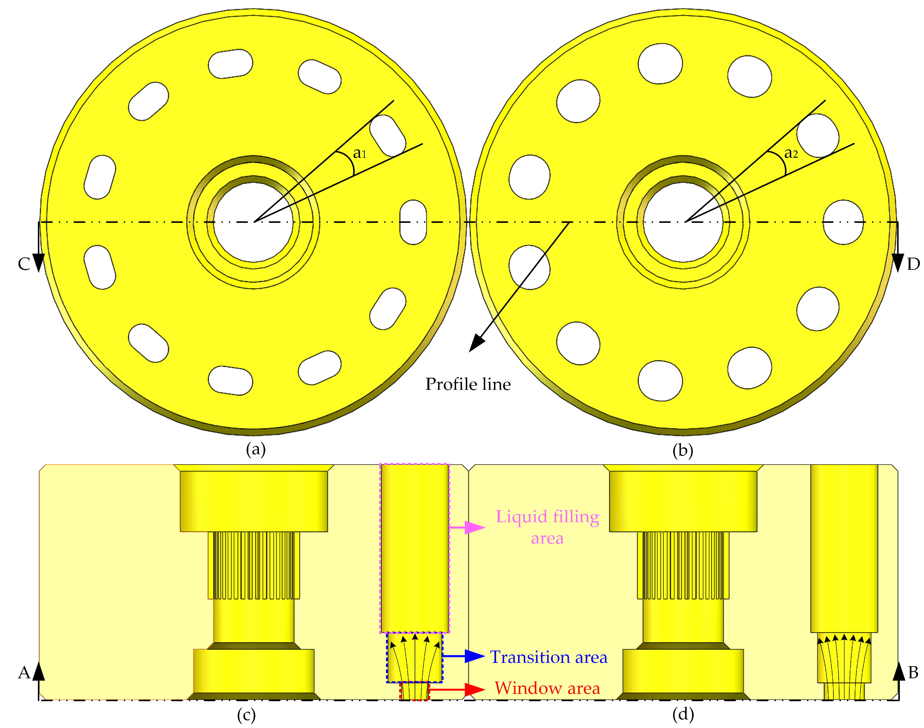
2.3. High-Speed Design of Piston Pumps

The extremely fast flow rate of hydraulic oil in the axial piston pump aggravates the cavitation phenomenon under high-speed situations. Because the pressure in the oil discharge area (the piston chamber, valve plate discharge port and oil discharge port in the oil discharge state) is extremely high, much higher than the saturation vapour pressure and air separation pressure of hydraulic oil, nearly no cavitation occurs. Cavitation occurs mainly in the suction state of the piston chamber due to low pressure in the suction area. Two factors contribute to the pressure drop in the piston chamber. The first is the loss of pressure throughout the suction process in the piston chamber, and the second is the pressure loss near the centre of rotation caused by the centrifugal force of rotation around the shaft [32,33].
The overflow surface of the window area of the traditional axial piston pump cylinder block is waist-shaped (Figure 6a,c), and the flow area is tiny, preventing the oil from flowing freely and effectively, resulting in a significant increase in pressure loss along the oil. The pressure loss is insignificant at low speeds, but at high operating speeds, the traditional structure’s along-range pressure loss increases dramatically, resulting in particularly severe cavitation in the piston chamber. In order to address this problem, the overflow surface of the window area has been improved to significantly increase the area of the overflow surface while maintaining the pack angle of the window area equal before and after the change ( a 1 = a 2 ) (Figure 6). The structure of the valve plate has been modified accordingly to match the modified window overflow surface, and the before and after views are not redundantly represented in this paper.

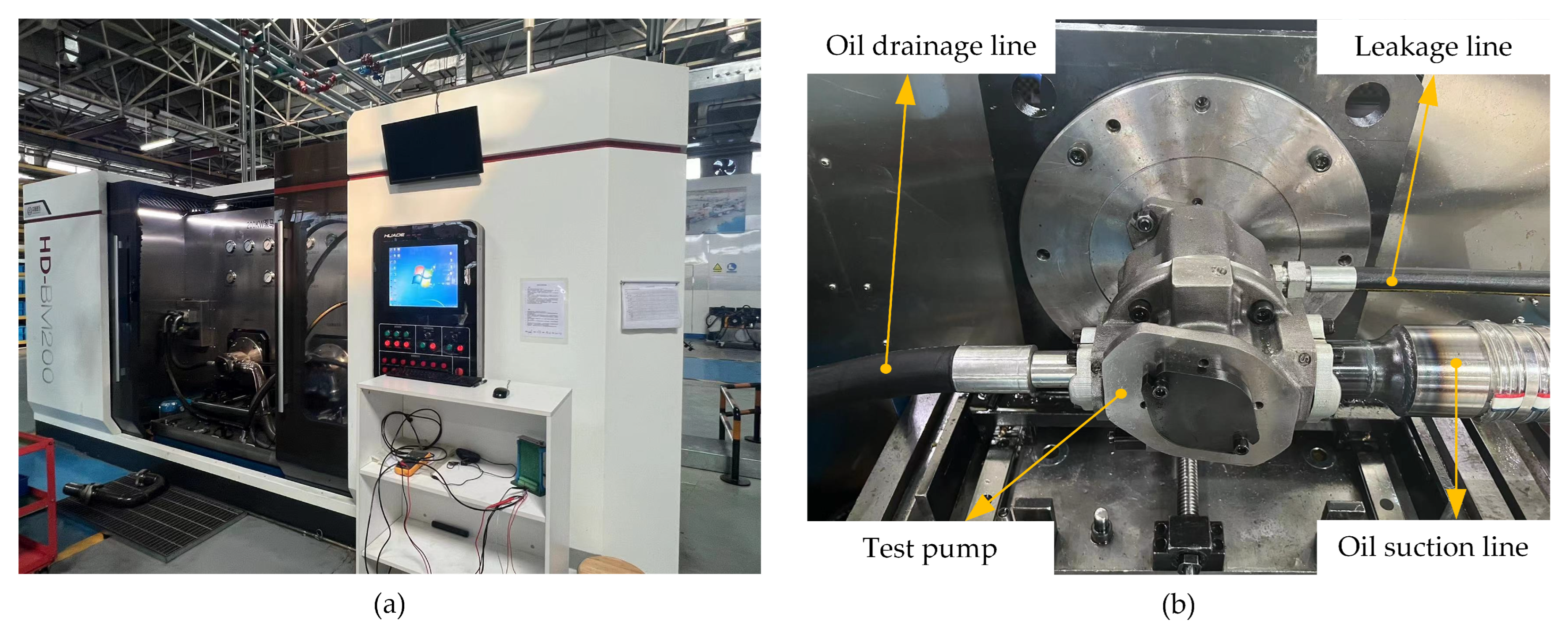
3. Validation of the Numerical Model

A piston pump flow test conducted by Suo et al. [34] was used to verify the correctness of the numerical model. A series of piston pump flow tests at different speeds were carried out on a comprehensive performance test bed. The comprehensive performance test bed and test piston pump are shown in Figure 7.
Based on the structural parameters and boundary conditions provided in the literature [34], a numerical model of the flow field inside the piston pump was developed using Pumplinx. A piston pump flow test at a suction pressure of 0.5 MPa and a discharge pressure of 20 MPa was used to validate the numerical model in this study.
The flow rate of the piston pump obtained by numerical simulation is compared with the experimental results given in the literature [34], as shown in Figure 8. The experimental results are in high accordance with the numerical simulation results, where the maximum error is 3.63%. It can be concluded that the numerical model based on the Full Cavitation Model, the compressible model and the standard k-ε turbulence model in Pumplinx is reasonably accurate in predicting the changes in the internal flow field in a piston pump.

4. Results and Discussion

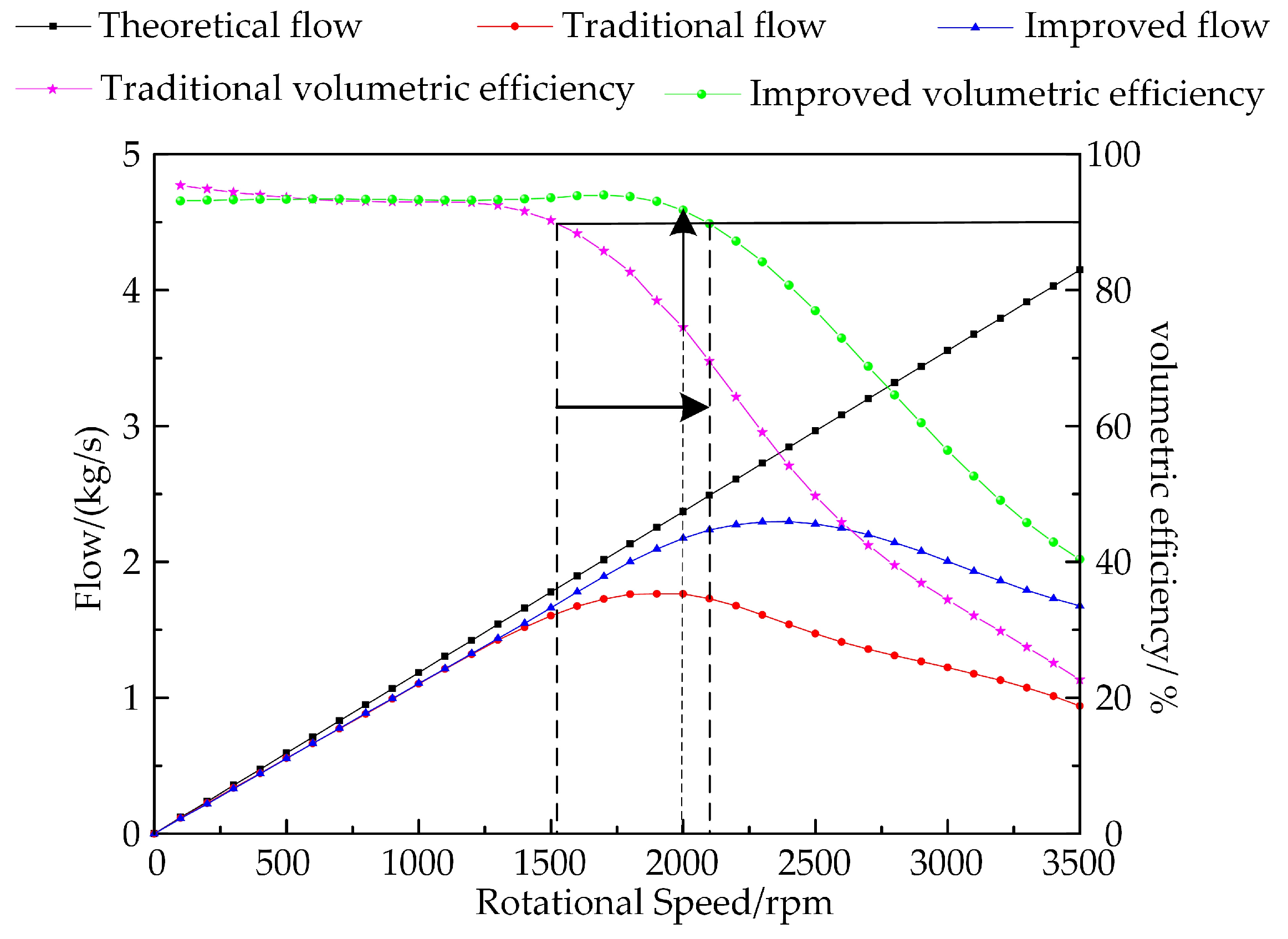
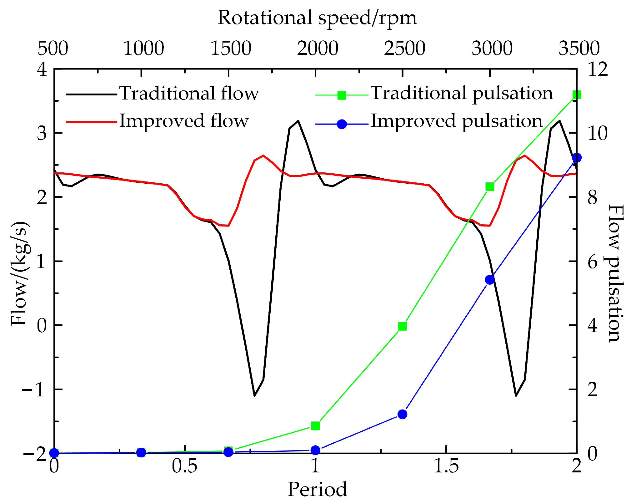
4.1. Flow Characteristics and Volumetric Efficiency of Piston Pumps

To make the description easier, the following uses traditional flow to represent the flow of the axial piston pump using the traditional cylinder, and the improved flow represents the flow of the axial piston pump using the improved cylinder. Figure 9 shows that when the piston pump’s rotational speed is less than 1500 rpm, there is no significant difference in flow rate and volumetric efficiency between the improved and traditional cylinder blocks. However, above 1500 rpm, the flow rate and volumetric efficiency of the piston pump increase greatly with the use of the improved cylinder block, and the maximum flow rate is increased from 1.765 kg/s to 2.295 kg/s. The maximum speed at which the volumetric efficiency remains above 90% is improved from 1500 rpm to 2100 rpm, greatly increasing the axial piston pump’s rated speed. At 2000 rpm, 2500 rpm, 3000 rpm and 3500 rpm, the volumetric efficiency of the conventional block was 74.465%, 49.649%, 34.390% and 22.640%, respectively, which were improved by 23.219%, 54.958%, 64.024% and 78.405% with the improved block. The flow rate of the conventional cylinder was 1.753 kg/s, 1.472 kg/s, 1.222 kg/s and 0.935 kg/s at different speeds and improved by 24.073%, 54.823%, 63.993% and 79.251%, respectively. It can be found that when rotating at high speed, the volumetric efficiency and flow rate of the piston pump, although decreasing with increasing speed, increases with increasing speed after the improvement.
The traditional flow pulsation equation is:
δ = Q max Q min 1 2 ( Q max + Q min )
where Q max and Q min are the maximum and minimum flow rates, respectively, and δ is the flow pulsation. Equation (17), which is dependent solely on the maximum and minimum values for calculating the flow pulsation rate, is incapable of accurately characterising the flow pulsation properties. As a result, a new method of characterising flow pulsation characteristics was proposed, in which the flow curve is discretised, and the mean squared difference is determined for each value using the expression:
δ 1 = 1 n 1 n ( Q avg Q i ) 2
Q a v g = 1 n ( Q 1 + Q 2 + Q 3 + + Q n )
The speed–pulsation curve is obtained by using the above pulsation calculation method and discretising the flow time history curve into 60 pieces (Figure 10). As the rotational speed increases, the flow pulsation also grows. At speeds below 1500 rpm, the flow pulsation of the enhanced cylinder is not noticeably different from that of the traditional cylinder. When the speed is more than 1500 rpm, the flow pulsation of the improved cylinder is significantly reduced. At 2000 rpm, the flow pulsation of the traditional block is 0.855, whereas that of the improved block is 0.090, a reduction of 89%. However, once the rotational speed is greater than 1500 rpm, the traditional flow becomes negative, which causes the hydraulic cylinder to vibrate more. After the cylinder body is improved, the negative flow will no longer emerge.
In conclusion, the volumetric efficiency of the piston pump is greatly increased, flow pulsation is reduced and the high speed of the axial piston pump is achieved by the use of improved cylinders at speeds exceeding 1500 rpm.

4.2. Mechanisms for Achieving High Speed of Piston Pumps

The following is an analysis of the reasons why improved cylinders can achieve high speeds from the perspective of inhibiting cavitation and backflow in the piston chamber.
The volume fraction characterises the degree of cavitation development. A higher volume fraction suggests that the region has more serious cavitation. The numerical model takes into account both vaporous cavitation and gaseous cavitation. The vapour volume fraction is used to characterise vaporous cavitation, and the dissolved gas volume fraction is used to characterise gaseous cavitation. The gas phase volume fraction serves to characterise the sum of the two types of cavitation because they both result in a reduced piston chamber filling rate. As shown in Section 4.1, the improved cylinder increases the volumetric efficiency of the piston pump and lowers flow pulsation, which indicates a considerable cavitation suppression effect at speeds exceeding 1500 rpm. In order to explore the gas phase volume fraction in the piston chamber, three sets of conditions were chosen: 2000 rpm, 2500 rpm and 3000 rpm.
The analysis is performed when the piston chamber is at 90°, and the lower dead point is at 0°. As shown in Figure 11, when the rotational speed is 2000 rpm, the gas phase volume fraction of the A and B zones of the piston chamber of the modified cylinder block reduces dramatically, and the gas phase volume fraction of the A zone decreases to 0. When the rotational speed is 2500 rpm or 3000 rpm, the gas volume fraction in the A and B zones of the piston chamber of the improved cylinder block does not decrease much due to the rise in centrifugal force, but the gas volume fraction of the entire piston chamber falls.
The variation of the gas phase volume fraction in the piston chamber with time for the traditional and improved cylinder blocks under three sets of operating conditions (Figure 12) exhibits that the improved cylinder block effectively suppresses cavitation in the piston chamber. The peak gas phase volume fraction in the piston chamber of the modified block dropped by 3.508%, 9.423% and 6.962%, respectively, at speeds of 2000 rpm, 2500 rpm and 3000 rpm, compared to the traditional block, greatly suppressing cavitation in the piston chamber. This is due to the increased window area and increasing piston pump discharge flow. While at the same rate of change in volume, the larger overflow surface reduces the suction speed to the critical cavitation speed. Therefore, under high-speed conditions, increasing the window overflow area can effectively inhibit cavitation in the piston pump.
The main form of cavitation in the piston pump at high speeds is vaporous cavitation. The magnitude of the vapour volume fraction reflects the degree of vaporous cavitation. The vapour volume fraction curves of both traditional and improved piston chambers are shown in Figure 13. The peak vapour volume fraction of the piston chamber is lowered by 0.492%, 1.498% and 4.250% for 2000 rpm, 2500 rpm and 3000 rpm, respectively, compared to the conventional cylinder block, as shown in the graph. As a result, the improved cylinder can effectively suppress vaporous cavitation in the piston chamber, and the quicker the speed, the better the effect of suppressing vaporous cavitation.
The filling rate of the piston chamber is considerably enhanced when the cylinder block is improved, as indicated in Table 2. At 2000 rpm, the piston chamber filling rate before and after improvement is 89.703% and 97.532%, respectively, and the volume efficiency is 74.465% and 91.755%. The liquid filling rate and volumetric efficiency of the piston chamber are not identical, owing primarily to backflow. The following equation is defined:
α = γ β
where α is the effective transport rate characterising the intensity of the backflow, β is the filling rate when the piston chamber is at the upper dead centre and γ is the volumetric efficiency. The larger the value of α , the weaker the backflow, and the smaller the value of α , the stronger the backflow. With the improved cylinder block, the effective transport rate increased by 11.064%, 23.208% and 22.401% for the three groups of conditions, respectively. The effective transport rate of the piston chamber is significantly increased, and the backflow is reduced based on the improved cylinder block.
Backflow takes place when the piston chamber is moved from the suction to the discharge area. Figure 14 depicts a cloud of backflow in the piston chamber of a traditional block when the rotational speed is 2000 rpm, ranging from 209° to 212°. The velocity vector is represented by the vector arrows, while the pressure is represented by the other cloud. Backflow will impact the piston chamber wall as the cylinder rotates, as shown in region C of the diagram. Figure 15 depicts the flow rate in the piston chamber’s discharge area. Backflow is shown by a positive flow rate in the graph, while normal discharge is represented by a negative flow rate. The maximum flow rate of backflow is reduced after the cylinder is improved, the duration is greatly shortened and the backflow phenomenon is reduced. The overall backflow mass of the traditional and improved blocks is 0.00374 kg and 0.00253 kg, respectively. The total backflow mass of the improved block is reduced by 32.4%.
In summary, the improved cylinder block can effectively inhibit the cavitation and backflow phenomenon in the piston chamber, thus enhancing the volumetric efficiency of the piston pump, reducing the flow pulsation and realising the high speed of the high-pressure axial piston pump.

5. Conclusions

In this work, an improved scheme for the problem of increased cavitation and reduced volumetric efficiency of high-pressure piston pumps at high speeds was proposed by enlarging the overflow area of the cylinder window area. A vertical dynamics model and a numerical model of the internal flow of the piston pump were developed to analyse the volumetric efficiency, flow characteristics and cavitation phenomenon of the improved axial piston pump at high speeds. The main findings are summarised as follows.
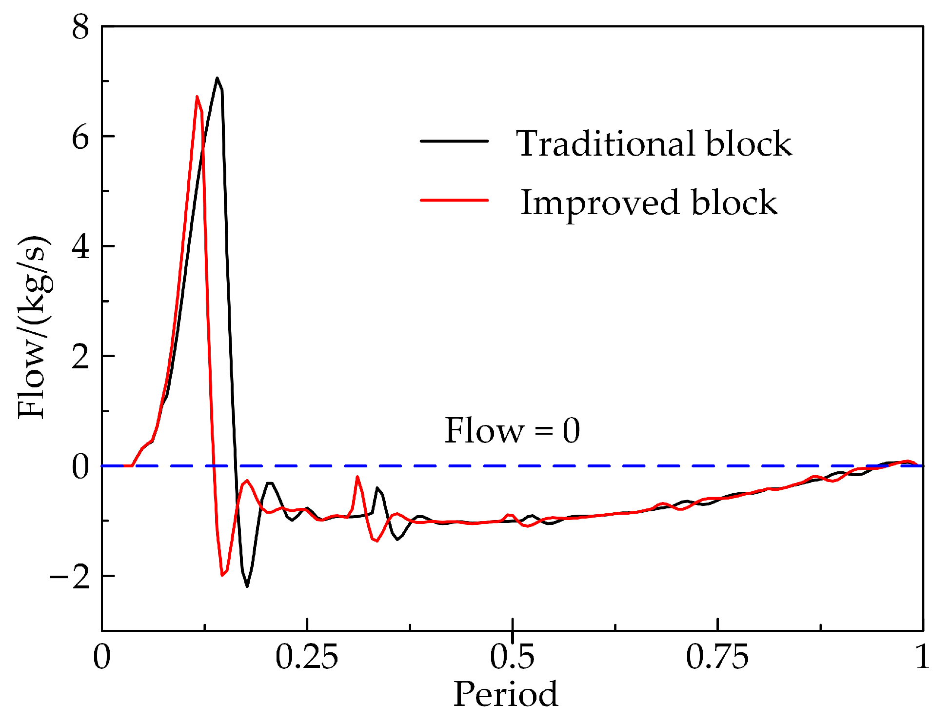
  • The volumetric efficiency and flow rate of the improved cylinder block change slightly at low speeds but increase considerably at high speeds. The maximum speed at which the volumetric efficiency of a traditional axial piston pump remains above 90% is 1500 rpm, while the improved cylinder increases to 2100 rpm. At 2000 rpm, 2500 rpm, 3000 rpm and 3500 rpm, the volumetric efficiency is increased by 23.219%, 54.958%, 64.024% and 78.405%, respectively. The maximum flow rate of the improved piston pump rises from 1.765 kg/s to 2.295 kg/s with different speeds, an increase of 30.028%. When the speed is increased over 1500 rpm, the flow pulsation of the improved cylinder is also greatly reduced.
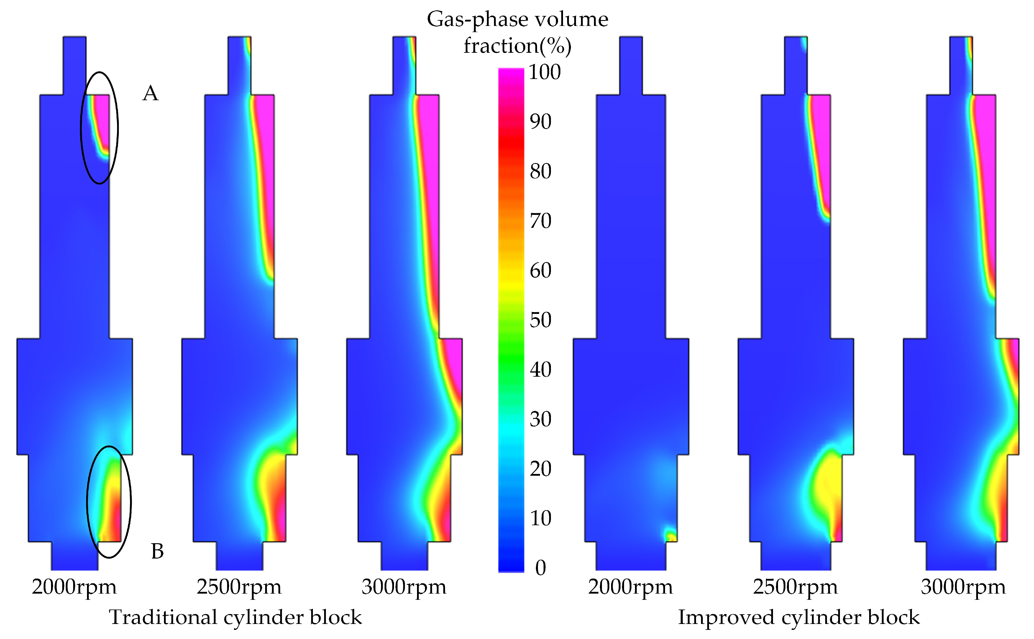
  • The improved block can effectively inhibit the cavitation and backflow of the piston chamber. When rotational speeds at 2000 rpm, 2500 rpm and 3000 rpm, the peak gas phase volume fractions of the improved block are reduced by 3.508%, 9.423% and 6.962%, respectively, and the peak vapour volume fractions in the piston chamber are reduced by 0.492%, 1.498% and 4.250%, respectively, while the effective transport rates are increased by 11.064%, 23.208% and 22.401%, respectively, compared to the traditional blocks. Backflow and cavitation in the piston chambers will be reduced, which will help to increase the volumetric efficiency of the piston pump, reduce flow pulsation and reduce the vibration and noise of the pump body, resulting in smoother hydraulic system performance.

Author Contributions

Methodology, software and writing—original draft preparation, M.H.; conceptualisation, supervision and project administration, Y.J. All authors have read and agreed to the published version of the manuscript.

Funding

This research received no external funding.

Institutional Review Board Statement

Not applicable.

Informed Consent Statement

Not applicable.

Data Availability Statement

The data presented in this study are available on request from the corresponding author. The data are not publicly available due to privacy.

Acknowledgments

The authors acknowledge Suo for his help in building numerical models.

Conflicts of Interest

The authors declare no conflict of interest.

References

  1. Zhang, B.; Hao, L. A review about missile unsupported combat and its capability requirements. Aerodyn. Missile J. 2017, 2017, 43–46+59. [Google Scholar] [CrossRef]
  2. Wu, X. Study on Electric Vertical Erection for Large Missile Launcher on Board. Ph.D. Thesis, Beijing Institute of Technology, Beijing, China, 2015. [Google Scholar]
  3. Feng, J.; Gao, Q.; Shao, Y.; Qian, W. Flow and pressure compound control strategy for missile hydraulic erection system. Acta Armamentarii 2018, 39, 209–216. [Google Scholar] [CrossRef]
  4. Feng, J.; Gao, Q.; Guan, W.; Li, L. Modeling of telescopic hydraulic cylinder and research on inter-stage buffer. Acta Armamentarii 2016, 37, 2268–2276. [Google Scholar] [CrossRef]
  5. Feng, J.; Gao, Q.; Guan, W.; Yao, X.; Li, L. Research on rapid missile erection system based on gas-hydraulic hybrid drive. Acta Armamentarii 2017, 38, 1348–1357. [Google Scholar] [CrossRef]
  6. Sao, Y.; Zhang, W.; Gao, Q.; Feng, J. Interior ballistics modeling and parameters optimization of erecting system with large inertia based on hybrid drive of gas and hydraulics. J. Propuls. Technol. 2018, 39, 751–759. [Google Scholar] [CrossRef]
  7. Ren, Y.; Gao, Q.; Tian, H. Optimization design and analysis of a rapid erection device based on gas-squeezer type power source. J. Vib. Shock. 2020, 39, 83–90. [Google Scholar] [CrossRef]
  8. Ren, Y.; Gao, Q.; Tian, H. Application of flow adjustable gas generator on missile erection device. J. Propuls. Technol. 2021, 42, 249–257. [Google Scholar] [CrossRef]
  9. Liu, X.; Li, M.; Hu, Y. Design of large hydraulic quick erecting system. Chin. Hydraul. Pneum. 2011, 6, 108–110. [Google Scholar]
  10. Chao, Q. Research on Some Key Technologies of High-Speed Rotation for Axial Piston Pumps Used in EHAs. Ph.D. Thesis, Zhejiang University, Zhejiang, China, 2019. [Google Scholar]
  11. Chao, Q.; Zhang, J.; Xu, B.; Huang, H.; Zhai, J. Centrifugal effects on cavitation in the cylinder chambers for high-speed axial piston pumps. Meccanica 2019, 54, 815–829. [Google Scholar] [CrossRef]
  12. Liu, C.; Wu, X.; Gan, X.; He, Y. Numerical simulation of cavitation flow in piston pump based on full cavitation model. China Mech. Eng. 2015, 26, 3341–3347. [Google Scholar]
  13. Chao, Q.; Tao, J.; Wei, X.; Wang, Y.; Meng, L.; Liu, C. Cavitation Intensity Recognition for High-Speed Axial Piston Pumps Using 1-D Convolutional Neural Networks with Multi-Channel Inputs of Vibration Signals. Alex. Eng. J. 2020, 59, 4463–4473. [Google Scholar] [CrossRef]
  14. Yin, F.; Nie, S.; Xiao, S.; Hou, W. Numerical and experimental study of cavitation performance in sea water hydraulic axial piston pump. Proc. Inst. Mech. Eng. Part I J. Syst. Control. Eng. 2016, 230, 716–735. [Google Scholar] [CrossRef]
  15. Han, J. Analysis of Flow Characteristic of Swashplate Axial Piston Pump. Master’s Thesis, Shandong University, Shandong, China, 2020. [Google Scholar]
  16. Tian, Z. Research on Cavitation Phenomenon of 250 cc/r Displacement Axial Piston Pump in the Process of Suction and Discharge. Master’s Thesis, Taiyuan University of Technology, Taiyuan, China, 2018. [Google Scholar]
  17. Ma, Y. Calculation and analysis of gas volume content in piston pump under different working conditions. Hydraul. Pneum. Seals 2020, 40, 18–22+26. [Google Scholar]
  18. Dong, H.; He, Y.; Wang, Y.; Kou, G. Numerical Investigation of Effect of a Centrifugal Boost Impeller on Suction Performance of an Aircraft Hydraulic Pump. Chin. J. Aeronaut. 2022, 35, 236–248. [Google Scholar] [CrossRef]
  19. Gao, D.; Suo, X.; Cai, Q.; Wu, S.; Liang, Y. Influence of key structural parameters of hydraulic piston pump on cavitation in pump. China Mech. Eng. 2018, 29, 434–440. [Google Scholar]
  20. Chao, Q.; Xu, Z.; Tao, J.; Liu, C. Capped Piston: A Promising Design to Reduce Compressibility Effects, Pressure Ripple and Cavitation for High-Speed and High-Pressure Axial Piston Pumps. Alex. Eng. J. 2023, 62, 509–521. [Google Scholar] [CrossRef]
  21. Ma, J.; Fang, Y.; Xu, B.; Yang, H. Optimization of cross angle based on the pumping dynamics model. J. Zhejiang Univ. Sci. A 2010, 11, 181–190. [Google Scholar] [CrossRef]
  22. Zhang, B.; Zhao, C.; Hong, H.; Cheng, G.; Yang, H.; Feng, S.; Zhai, J.; Xiao, W. Optimization of the Outlet Unloading Structure to Prevent Gaseous Cavitation in a High-Pressure Axial Piston Pump. Proc. Inst. Mech. Eng. Part C J. Mech. Eng. Sci. 2022, 236, 3459–3473. [Google Scholar] [CrossRef]
  23. Zhang, H. Cavitation Characteristics Analysis of Distribution Pair of High Temperature Fuel Piston Pump. Master’s Thesis, Zhejiang University, Zhejiang, China, 2019. [Google Scholar]
  24. Tsukiji, T.; Takase, T.; Noguchi, E. Visualization analysis of cavitating jet flow issuing from notch in an axial piston pump. Trans. Jpn. Fluid Power Syst. Soc. 2011, 42, 7–12. [Google Scholar] [CrossRef] [Green Version]
  25. Tsukiji, T.; Chen, Z.; Chen, J. Visualized analysis of cavitation inside axial piston pump. Chin. Hydraul. Pneum. 2015, 2, 1–7. [Google Scholar]
  26. Yu, F.; Zhang, J.; Xu, B.; Zebing, M.; Li, C.; Huang, C.; Fei, L.; Zhimin, G. Raising the Speed Limit of Axial Piston Pumps by Optimizing the Suction Duct. Chin. J. Mech. Eng. Ji Xie Gong Cheng Xue Bao 2021, 34, 105. [Google Scholar] [CrossRef]
  27. Chao, Q.; Zhang, J.; Xu, B.; Huang, H.; Zhai, J. Effects of inclined cylinder ports on gaseous cavitation of high-speed electro-hydrostatic actuator pumps: A numerical study. Eng. Appl. Comput. Fluid Mech. 2019, 13, 245–253. [Google Scholar] [CrossRef] [Green Version]
  28. Sun, Z. Study on Cavitation Resistance of Swash Plate Axial Piston Pump Cylinder and Valve Plate. Ph.D. Thesis, Southwest Jiaotong University, Chengdu, China, 2017. [Google Scholar]
  29. Guan, C.; Jiao, Z.; He, S. Theoretical study of flow ripple for an aviation axial-piston pump with damping holes in the valve plate. Chin. J. Aeronaut. 2014, 27, 169–181. [Google Scholar] [CrossRef] [Green Version]
  30. Singhal, A.K.; Athavale, M.M.; Li, H.; Jiang, Y. Mathematical basis and validation of the full cavitation model. J. Fluids Eng. 2002, 124, 617–624. [Google Scholar] [CrossRef]
  31. Iannetti, A.; Stickland, M.T.; Dempster, W.M. A CDF and experimental study on cavitation in positive displacement pumps: Benefits and drawbacks of the ‘full’ cavitation model. Eng. Appl. Comput. Fluid Mech. 2016, 10, 57–71. [Google Scholar] [CrossRef] [Green Version]
  32. Manring, N.D.; Mehta, V.S.; Nelson, B.E.; Graf, K.J.; Kuehn, J.L. Scaling the speed limitations for axial-piston swash-plate type hydrostatic machines. J. Dyn. Syst. Meas. Control 2014, 136, 031004. [Google Scholar] [CrossRef]
  33. Kunkis, M.; Weber, J. Experimental and Numerical Assessment of an Axial Piston Pump’s Speed Limit; American Society of Mechanical Engineers Digital Collection: Bath, UK, 2016. [Google Scholar]
  34. Suo, X.; Jiang, Y.; Wang, W.; Gao, D.; Zhang, X. Cavitation flow characteristics and optimization of high-pressure pumps in the hydraulic system of aircraft control surfaces. Acta Aeronaut. Astronaut. Sin. 2023, 44, 127402. [Google Scholar]
Figure 1. Diagram of launch vehicle erection.
Applsci 13 07178 g001
Figure 2. Diagram of erection.
Applsci 13 07178 g002
Figure 3. Hydraulic bearing capacity of erection. The blue line means that the hydraulic capacity bearing is equal to 0.
Applsci 13 07178 g003
Figure 4. Diagram of an axial piston pump.
Applsci 13 07178 g004
Figure 5. Fluid domains Meshes of an axial piston pump.
Applsci 13 07178 g005
Figure 6. Simplified two views of traditional and improved cylinder blocks. A–D letters are the identifications to the reference arrow views. (a) Bottom view of traditional cylinder block; (b) Bottom view of improved cylinder block; (c) Front view section of traditional cylinder block; (d) Front view section of improved cylinder block.
Applsci 13 07178 g006
Figure 7. (a) The comprehensive performance test bed and (b) Test pump [34].
Applsci 13 07178 g007
Figure 8. Comparison of experimental and numerical simulation results.
Applsci 13 07178 g008
Figure 9. Traditional and improved flow rate and volumetric efficiency at different rotational speeds.
Applsci 13 07178 g009
Figure 10. Traditional and improved flow rate time travel curve at 2000 rpm and flow pulsation at different rotational speeds.
Applsci 13 07178 g010
Figure 11. Traditional and improved gas-phase volume fraction cloud map of the piston chamber.
Applsci 13 07178 g011
Figure 12. Traditional and improved gas-phase volume fraction curve of the piston chamber.
Applsci 13 07178 g012
Figure 13. Vapour volume fraction curve.
Applsci 13 07178 g013
Figure 14. Backflow cloud of traditional block with different angles at 2000 rpm. (a) 209°; (b) 210°; (c) 211°; (d) 212°.
Applsci 13 07178 g014
Figure 15. Flow rate of traditional and improved piston chamber at 2000 rpm.
Applsci 13 07178 g015
Table 1. Boundary conditions and structural parameters.
DescriptionValueDescriptionValue
Inlet pressure0.101325 MPaAir dissolved volume13%
Outlet pressure25 MPaSaturation vapour pressure400 Pa
Swash-plate angle15°Hydraulic oil density800 kg/m3
Air molar mass28.97 kg/kmolModulus of elasticity of hydraulic oil1.5 × 109 Pa
Number of pistons11Viscosity7 × 10−3 Pa·s
Outer radius of piston10 mmHydraulic oil temperature25 °C
Radius of piston distribution circle48 mm--
Table 2. Filling rate and effective transportation rate of the piston chamber.
Rotational Speed
(rpm)
Traditional Cylinder BlockImproved Cylinder Block
Filling RateVolume
Efficiency
Effective
Transportation Rate
Filling RateVolume
Efficiency
Effective
Transportation Rate
200089.703%74.465%83.013%97.532%91.755%94.077%
250081.055%49.649%61.254%91.089%76.936%84.462%
300075.148%34.390%45.763%82.753%56.408%68.164%
Disclaimer/Publisher’s Note: The statements, opinions and data contained in all publications are solely those of the individual author(s) and contributor(s) and not of MDPI and/or the editor(s). MDPI and/or the editor(s) disclaim responsibility for any injury to people or property resulting from any ideas, methods, instructions or products referred to in the content.

