Article

Safety and Stability Analysis of Demolition and Reconstruction of Existing Railway Bridge Piers and Caps

1
Changsha Railway Survey and Design Co., Ltd., Changsha 410075, China
2
School of Civil Engineering, Central South University, Changsha 410075, China
*
Author to whom correspondence should be addressed.
Appl. Sci. 2023, 13(12), 7213; https://doi.org/10.3390/app13127213
Submission received: 16 May 2023 / Revised: 9 June 2023 / Accepted: 13 June 2023 / Published: 16 June 2023

Abstract

:

Featured Application

In this paper, a bearing in situ replacement scheme for an existing busy railway bridge is proposed; its safety and stability in the critical process of construction are analyzed, and the implementation scheme, problems, and their solutions in the actual construction are introduced, which can provide a reference for the practical application of the related projects.

Abstract

The process of bridge reconstruction often involves the demolition and reconstruction of bridge piers and caps, while most of the construction methods used in the previous bridge reconstruction projects changed the bridge-bearing positions. In this paper, an in situ replacement scheme of bridge piers and caps is proposed, which can maintain the existing stress state of the bridge without changing the bearing position. In order to figure out the safety and stability of the in situ replacement scheme of existing railway bridges, a steel support system model for the removal and reconstruction of the bridge piers and caps is established by ABAQUS, according to a domestic railway bridge reconstruction project, and verified by field measurement test. Based on the model, the stress and deformation of the steel support system under a trainload are analyzed, as well as those of the bearing foundation and the superstructure. The results show that the steel support system and steel pipe piles located directly below the line carrying the trainload are subjected to the greatest stress and deformation. While under various load conditions, the stress and deformation of the main components in the steel support system of the in situ replacement scheme meet the design requirements, and the structure is safe under a trainload. In addition, guided by the numerical calculation results, the implementation scheme, existing problems, and solutions of the project are introduced in detail, which can provide a reference for similar projects.

1. Introduction

In the process of water management, some existing waterways need to be dredged to expand their navigability and flood control capacity [1,2,3], which typically involves the modification of some piers, caps, and pile foundations of the bridges, such as pile buttress replacement, pile cap reinforcement, and other alterations [4,5], which is also the key to improve the service life of the bridges.
The applications of steel brackets are studied as follows: to check the safety of steel pipe brackets in the construction stage, Deng et al. [6] established the finite element model of steel pipe brackets and the field-measured steel pipe stress with MIDAS software. Horyl [7] and Bobet [8] et al. used finite element software (e.g., ANSYS, ABAQUS, etc.) to study the force characteristics of steel brackets, obtained the dynamic characteristics of steel braces, verified the expressions for structural stress and displacement, and proposed the optimal design spacing method. Rodríguez et al. [9] proposed a specific expression for yielding steel ribs based on the convergence–confinement method, which is capable of explaining the arch behavior and is easily used. Khalymendyk et al. [10] used a simple approach, including Kirsch equations, to analyze the stress distribution around the roadway. Rotkegel et al. [11] assessed the impact of bearing plate dimensions on the interaction of steel arch support and rock mass based on laboratory tests and numerical calculations. Zang et al. [12,13] prefabricated steel pipe concrete arches on the ground, feeding these arches into the ground and connecting these arches with flanges to form the roadway supports, which have a high load capacity and are compressible. Huang et al. [14] developed a concrete-filled steel tubular support for long-term, large-scale deformation of deep roadways and verified the outstanding advantages of this support in improving the bearing capacity and structural stability. To explore the mechanism of concrete-filled steel tubular support in deep roadways, Zhang et al. [15] compared the mechanical performances of U-steel supports and concrete-filled steel tubular supports by theoretical calculation and numerical simulation. At present, the application fields of steel brackets are more extensive, such as underground mine working and supporting roadways, but there is a lack of research on the application of steel support systems in the process of bridge reconstruction.
In the field of bridge reconstruction, there are numerous studies on the major methods and stability analysis during the procedure of bridge rebuilding and construction. Fu et al. [16] adopted the Analytic Hierarchy Process (AHP) method to analyze the multi-source data and set the early warning threshold for bridge safety in construction based on the multi-source data of nearby construction and demolition construction of a large-span RC arch bridge in China. Han et al. [17] considered a new type of corrosion-resistant steel, A709-50CR, for girder replacement. The reliability- and risk-based bi-objective optimizations were conducted on a multi-girder carbon steel bridge to determine when and which carbon steel girders should be replaced under different target performance indicators. Seyed et al. [18] investigated the effects of different alternatives for superstructure and substructure systems on the progressive collapse procedure after verifying the bridge collapse procedure. In addition, the application of restrainers at the connection of the deck to the abutment was studied as an effective solution in order to prevent collapse propagation and minimize associated damages. Tazarv et al. [19] performed an experimental investigation to systematically determine the seismic performance of mechanically spliced bridge columns and to develop the most comprehensive test database for these columns. Mansouri et al. [20] investigated the effects of the earthquakes’ duration, intensity, and magnitude on the seismic response of reinforced concrete bridges retrofitted with seismic bearings. Based on the deformation coordination principle and suspension cable theory, Huang et al. [21] proposed a practical calculation method that can calculate the load of the tower acting by a cable system in the cable lifting construction of arch bridges, to calculate and analyze cable lifting construction more quickly and accurately. Moreover, a large-span arch bridge under construction was used as a case study, and the correctness of the calculation method was verified by measuring the displacements of the tower top. Li et al. [22] proposed using the Copula function to calculate the reliability index of the bridge structure construction process system. The basic theory of the Copula function was introduced in detail, and the formula was improved according to the actual situation of bridge construction. As can be seen, most of the construction methods used in the previous bridge reconstruction projects changed the bridge-bearing positions, which had an unpredictable impact on the safety of the existing bridge and increased the disturbance to the traffic on the bridge.
Given the above-mentioned unfavorable factors and the inadequacy of existing studies, some of the alteration programs of existing railroad bridges can be optimized to bear an in situ replacement scheme. That is, special steel sections are used at the existing railway bridge bearings instead of piers and bearing pads without changing the position of the bridge bearings and maintaining the existing stress state of the railway bridge (Figure 1). In this scheme, the span of the girder is not changed, making the construction process and force form of the steel support simpler. At the same time, there is minimal impact on the force of the existing railway bridge girder, which can minimize the disturbance to the ballast bed and reduce the line-blocking time. However, the deformation and stress of the steel support structure under load still need to be further studied to determine the safety and stability of this construction scheme. Accordingly, a numerical simulation of the superstructure and support system model is carried out in this paper based on the actual bridge reconstruction project. Based on the established model, the force and deformation of the temporary support system under the trainload, as well as the deformation of the bridge and track components supported by this system, are investigated. The safety and stability of the construction critical process are analyzed considering the bearing capacity, stability, deflection of the steel brace, and the bearing capacity of the braced steel pipe pile. In addition, the problems and solutions in the actual construction case are introduced, which can provide a reference for the related projects.

2. Numerical Model

2.1. Finite Element Model

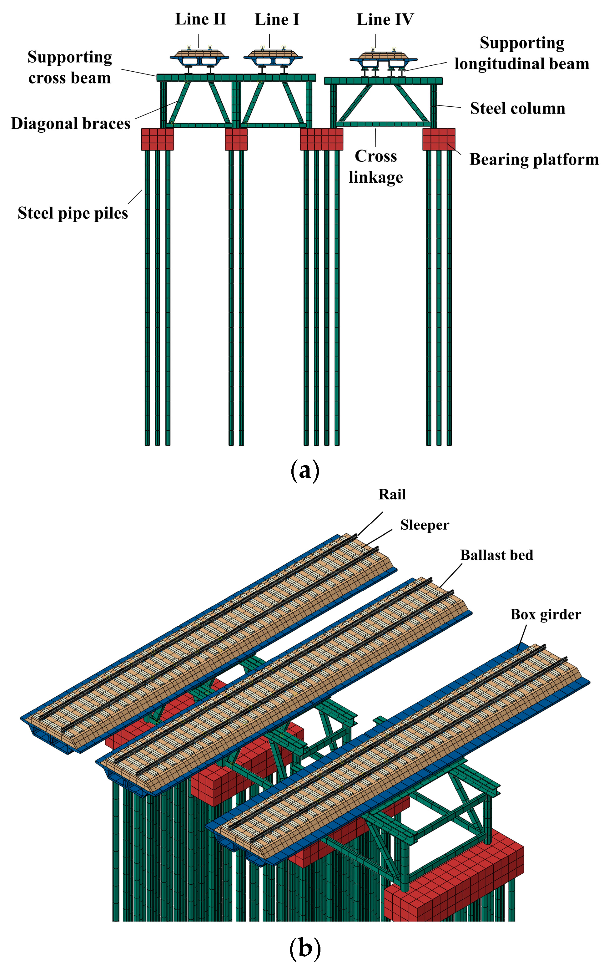
The model established in this paper (Figure 2) is based on a domestic railway viaduct (including the bridge of lines I, II, IV) located in a right-angle turning section of the river (Figure 3). The distance between the I and II lines of the railway viaduct is 5 m, while the spacing between line IV and line I is 7.5 m. The bridges of the lines I and II are simple-supported girder bridges of length (8 + 10 + 20 + 2 × 10 + 2 × 8) m, while the length of the line IV bridge is (3 × 10 + 20 + 2 × 10 + 2 × 8) m.
The finite element model is mainly composed of the superstructure (box girder, ballast bed, rail, sleepers, etc.), temporary steel bracket system, etc. The temporary steel bracket system structure is composed of supporting longitudinal beams, supporting cross beams, steel columns, diagonal braces, cross-linkages, temporary steel bracket bearings, and steel pipe piles from top to bottom. The supporting longitudinal beams and supporting cross beams are made of H500 × 500 special steel with a thickness of 4 cm. The steel column is divided into two types: side-span steel column; and middle-span common steel column. The side-span steel column has a 40 cm diameter and a 10 mm wall thickness, while the diameter of the middle-span common steel column is 60 mm, and the wall thickness is 10 mm. The diagonal braces, cross-linkages, and longitudinal linkages are made of H300 × 200 sealed edge steel diagonal braces; the temporary steel bracket bearing platforms are 1.5 m in height, with a width that corresponds to the original bearing platform spacing of the bridge piers. The steel pipe piles are solid piles with a diameter of 30 cm and a length of 20 m, and the center distance between each pile is 0.7 m. Relevant material parameters are shown in Table 1 [23,24].
In the establishment of the ballast track finite element model, the interlocking force between ballast particles is ignored, which is considered a continuous medium and simulated by solid elements [25,26,27]. The type of rail is CHN60, coupled to the sleepers by fasteners simulated by spring–damper element [28,29]. The type-III fastener is adopted, whose stiffness is 120 MN/m in the vertical direction, 40 MN/m in the lateral direction, and 20 MN/m in the longitudinal direction [30]. The damping is 2 × 10⁴ N·s/m in all three directions. In the process of establishing the finite element model, the shape of the sleeper is simplified to a regular rectangular body. The eight-node element-C3D8R is adopted to simulate the ballast, rail, and sleeper.
The bottom of the steel pipe pile is fixedly restrained, and the two ends of the bridge girder are fixedly restrained for simulating the support of the bridge piers. The ballast bed is composed of a bulk structure, which keeps close to the bridge deck under the trainload; thus, the ballast bed and the bridge deck are bonded together by the “tie constraint”. The contact between the rail sleepers and the ballast bed is simulated as a “surface-to-surface contact”, the normal contact is set as “hard contact”, while the Coulomb friction model with a friction coefficient of 0.3 is adopted as the tangential contact. The supporting longitudinal beams, supporting crossbeams, steel columns, diagonal braces, and other bars are connected by continuous fillet welds, thus setting the contact between them as a “tie restraint”.

2.2. Model Validation

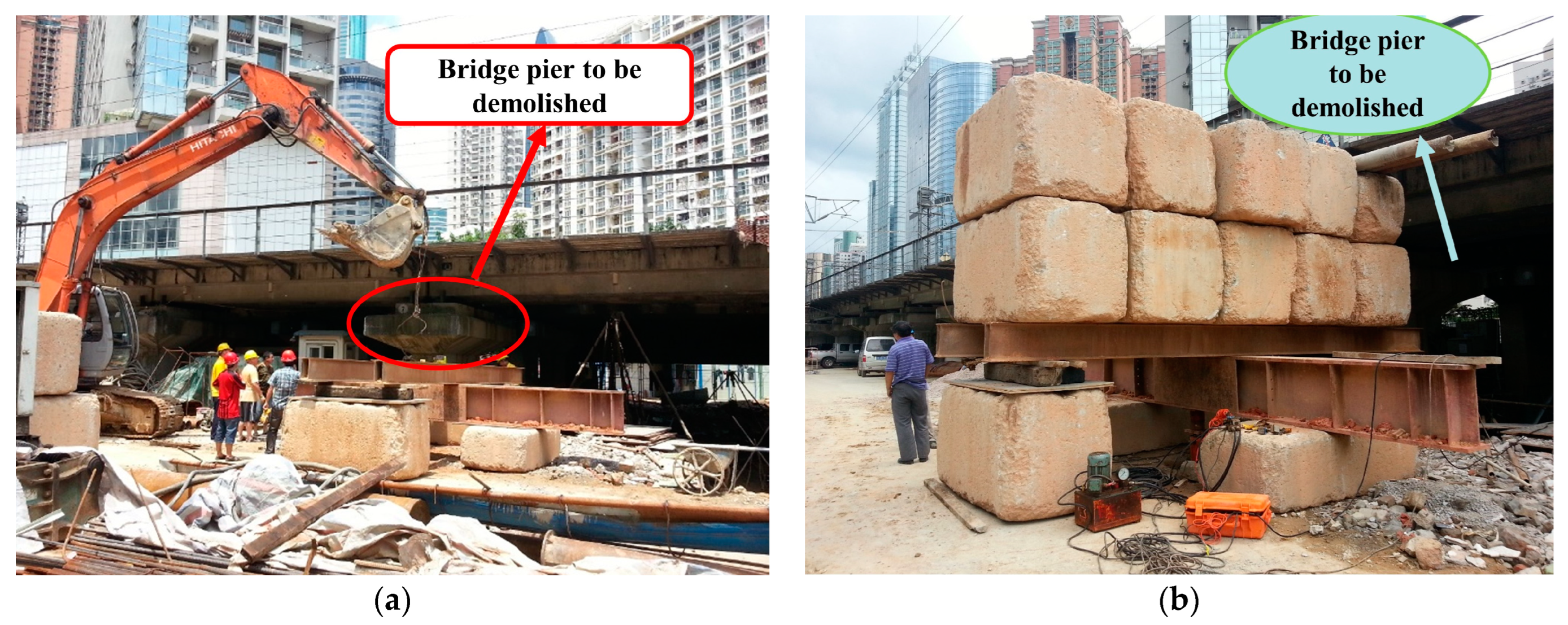
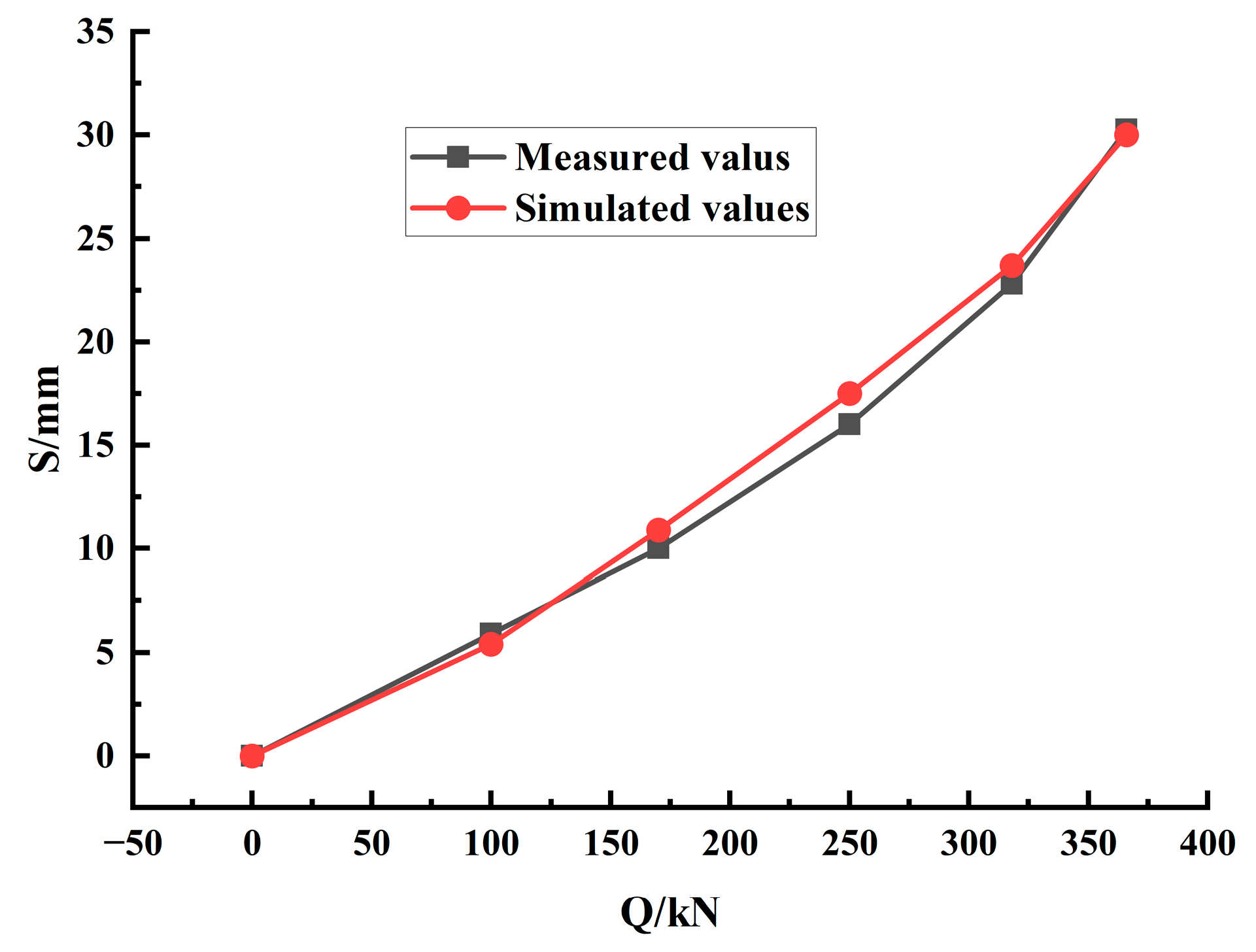
To ensure that the bearing capacity of the steel pipe pile meets the requirements, a single pile-bearing capacity test is conducted. Since there is no sufficient space for loading under the bridge, its adjacent location with the same stratum was selected for the loading test (Figure 4). In order to verify the reliability of the model, the mechanical parameters of the site soil are selected, and the numerical simulation of the single pile static load test of the pile foundation in the established model is carried out and compared with the data measured on site. The effect of the load at a distance from the pile is negligible, so the dimension of the soil model is set to 20 times the pile diameter in the radial direction (6 m) and 1 time the pile length in the vertical direction (20 m). The Mohr–Coulomb constitutive model is used to simulate the soil; the material parameters are shown in Table 2.
The Q-S curve is shown in Figure 5. It can be seen that there is a certain error between the measured and simulated values, which is due to the fact that the friction coefficient μ between pile and soil used in the numerical simulation cannot be obtained accurately, but the basic trend of the simulated and measured data development is consistent, which proves the correctness of the model.

2.3. Selection of Working Conditions

The engine of the train is simplified as 5 concentrated loads weighing 22 t, denoted by F, while the vehicle is simplified as a uniform load weighing 9.2 t/m, denoted by q. By comparing the force of the bearings under different action positions of the simplified static load during train operation, the working condition with the largest concentrated force transferred from the bearing to the lower support system is obtained, which is the most unfavorable load condition of the temporary steel bracket structure.
The train operation is divided into the following four working conditions to determine the most unfavorable load condition for the steel support structure: the fourth axle operates at the rightmost end of the first span; the fifth axle operates at the rightmost end of the first span; the fifth axle is 1.5 m from the rightmost end of the first span; and the fifth axle is 3 m from the rightmost end of the first span. The concentrated forces transmitted downward from the temporary support of the box girder under the four working conditions are calculated, as shown in Table 3.
In summary, the maximum total concentrated force transmitted downward from the temporary support under working condition 2 is the largest, which means the fifth axle operates at the rightmost end of the first span is the most unfavorable load position of the temporary steel support structure; thus, the stress state is selected for subsequent calculation. The distribution of the trainload in this working condition is shown in Figure 6. In the process of simulation, the trainload is applied in the form of a static load. A pressure of 9.07 × 10⁵ N/m2 is applied in the region where the uniform load q acts as shown in Figure 6, while a concentrated force of value 110,000 N is applied in each of the five places where the concentrated force F acts as shown in Figure 6.

3. Force Analysis of Steel Bracket

The cases of the most unfavorable trainload acting on each of the three lines of this bridge are considered and classified as follows (Figure 7): Case 1: trainload applied on line I; Case 2: trainload applied on line II; Case 3: trainload applied on line IV. The maximum stress of each component in the support system under the three cases is obtained through finite element calculation and analysis, as shown in Table 4.
From Table 4:
(1)
The middle-span steel columns directly bear the trainload transferred by the supporting longitudinal beam and cross-beam when the trainload operates on line I and line II, whereas the trainload acting on line IV has no direct effect on the middle-span steel columns, which only bear the self-weight generated by the superstructure, so the maximum stress of the middle-span steel columns under case 3 is 35% of that under case 1 and 2;
(2)
The diagonal braces are subjected to the greatest stress among the components in the three cases, whose maximum stress is less than the yield strength of Q235 steel [31], indicating that the entire steel bracket system is in an elastic stage under the trainload, which means that the bracket design can meet the safety requirements.
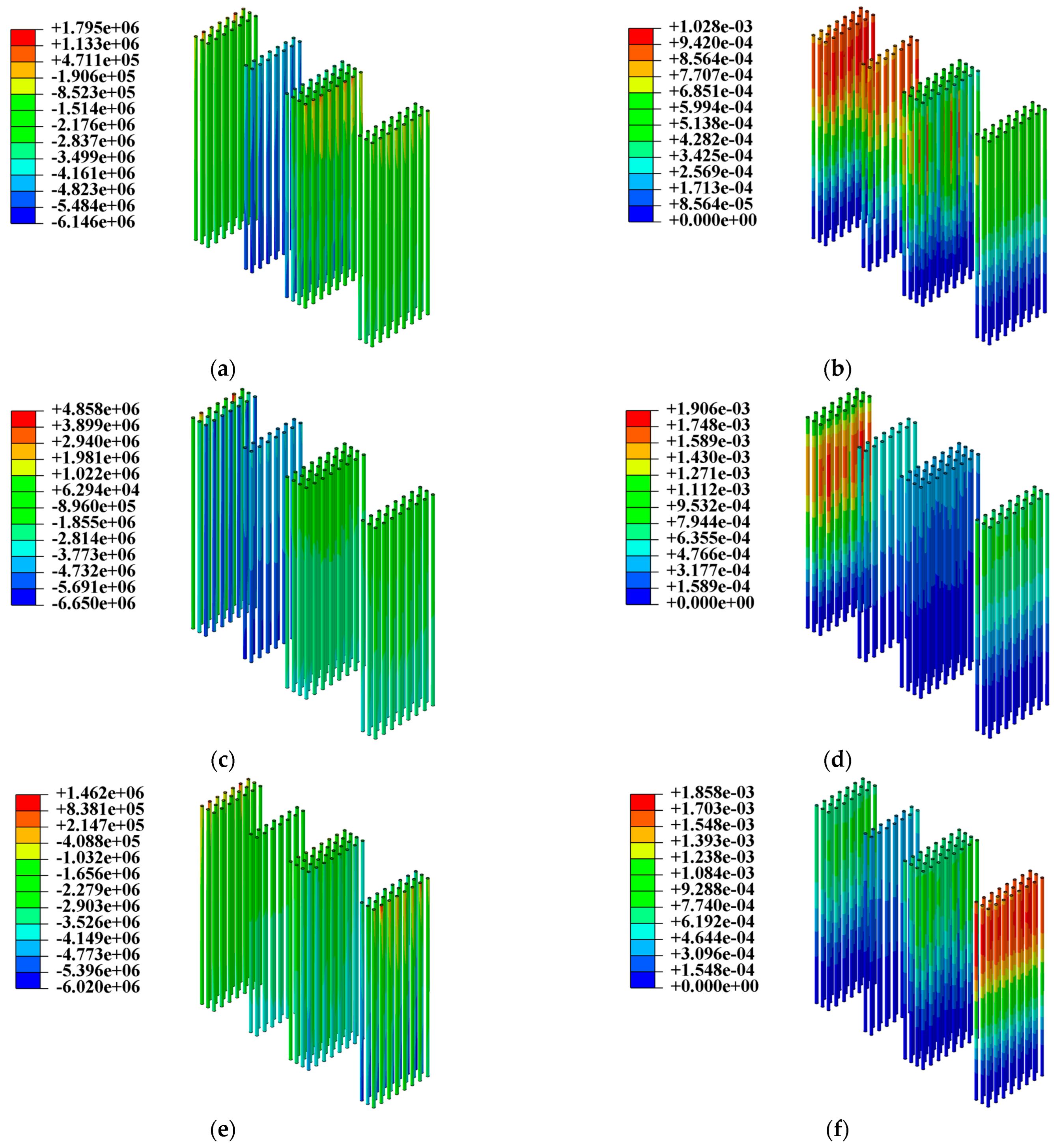
The stress condition of the steel pipe piles can reflect the force law of the bridge and steel support system structure under the trainload for the train, and the superstructure load is mostly passed from the steel pipe piles to the foundation. Figure 8 illustrates the analysis of the stress and displacement cloud diagram of the steel pipe piles in each case. The maximum stress of the steel pipe pile is  σ max = 6.65   MPa   <   f d = 215   MPa , which meets the design requirements. Under these cases, the steel pipe piles located directly below the line of the trainload are subjected to the greatest force. The maximum stress appears at the bottom of the pile, while the maximum displacement appears at the top of the pile, and the magnitude of stress and displacement of the steel pipe piles decreases from the area affected by the trainload to both sides.
The steel structure is permitted to deflect up to 1/400 of its span length under the effect of constant load and live load [31]. The allowable deflection of the supporting longitudinal beam in the temporary support is 2800/400 = 7 mm, and the allowable deflection of the supporting cross beam is 5000/400 = 12.5 mm. The maximum deflections of the longitudinal beams and cross beams, respectively, are 2.13 mm and 2.05 mm, which are less than the allowable deflection and satisfy the requirements from Table 5.
The comparison of case 1 and case 2 demonstrates that the maximum deflection of the longitudinal beams in line IV is 2.07 times and 1.82 times that in line I and line II, respectively, due to a greater distance between the two intersection points of the longitudinal beams and the supporting crossbeams below. At the same time, there are 60 cm diameter middle-span steel columns in the steel brackets under lines I and II to share the force of the side-span steel columns and diagonal braces, which enhances the stiffness of the brackets. As a result, the maximum deflection of the cross beam is 47% of what it is in case 3.
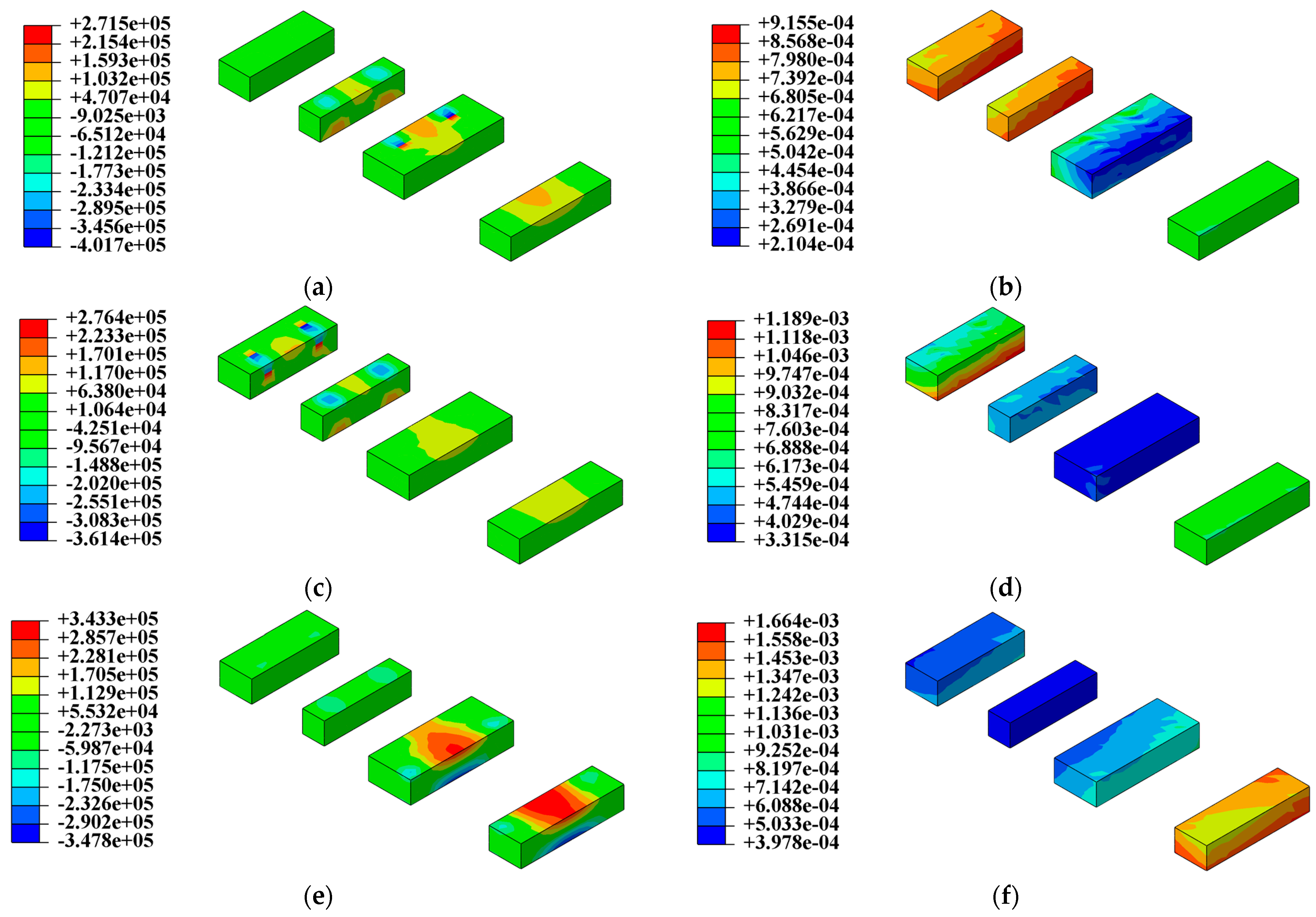
The stress and displacement cloud diagrams of the bearing under the trainload are depicted in Figure 9, in which the maximum longitudinal compressive stress of the bearings under the 3 cases is 0.402 MPa, 0.361 MPa, and 0.348 MPa, and the maximum tensile stress is 0.272 MPa, 0.276 MPa, and 0.343 MPa, respectively. The area of the bearing platforms attached to the steel columns below the train line of action presents a noticeable rise in stress, and the stress away from this area gradually declines. The maximum stress is lower than the tensile and compressive strengths of concrete. The bearing platform directly subjected to the trainload appears to have the largest displacement with maximum deformation of 0.9155 mm, 1.189 mm, and 1.664 mm, respectively.

4. Displacement and Stress of Bridge and Track Components

Table 6 demonstrates the displacement analysis results of the track structure and the box girder, indicating that in the identical case, the displacement of the superstructure has a certain correlation with its substructure under the force of its own gravity; consequently, the displacements of the components in the track structure remain essentially the same as those of the box girder. In cases 1 and 2, the displacements of each component are smaller than those in case 3, suggesting that the overall stiffness of the supporting structure in line I and line II is higher than that in line IV.
The maximum tensile and compressive stress of the track components is below the strength limit, which is not significantly different in all three cases, according to the results of the stress analysis in Table 6. At the same time, the stress of the ballast bed in condition 3 is greater than that in condition 1 and condition 2. By comparing its displacement value in different conditions, it can be seen that this is mostly caused by the larger displacement and deformation of the ballast bed in condition 3, thus causing a compressive stress value 1.46 times those in conditions 1 and 2.
The results of the numerical simulation for stress and displacement of bridge and track structure under case 1 are shown in Figure 10. Among them, the maximum tensile and compressive stress appears at the point of concentrated force action in the rail. Meanwhile, the displacement of the rail structure in the line under trainload action is significantly greater than those in other lines.

5. Technical Solutions for On-Site Construction

5.1. Railroad Bridge Bearing In Situ Bracket Replacement Technology

The construction process of railway bridge-bearing support replacement is as follows: reinforcing existing piers, constructing steel pipe piles → constructing support bearings → installing temporary steel support → blocking railway for bearing support beams installation construction → cutting and removing existing pier bearings in pieces → excavating the pier pit → pouring pier bearing reinforcement concrete → pouring pier reinforcement concrete → pouring pier cap reinforcement concrete → cutting bearing bracket replacement beam, removing temporary steel bracket → completion and acceptance.

5.1.1. Construction of Steel Pipe Pile

The steel pipe piles are mainly divided into existing bridge pier reinforcement steel pipe piles and temporary support steel pipe piles. The construction process is as follows: leveling site → processing steel pipe piles → measuring and positioning →aligning the drilling rig → drilling → drill-hole finished → cleaning the hole → lowering the steel pipe → secondary hole cleaning → filling cement slurry until pure cement slurry flows out of the hole → dumping stones inside the steel pipe piles and pounding.

5.1.2. Construction of Temporary Steel Bracket

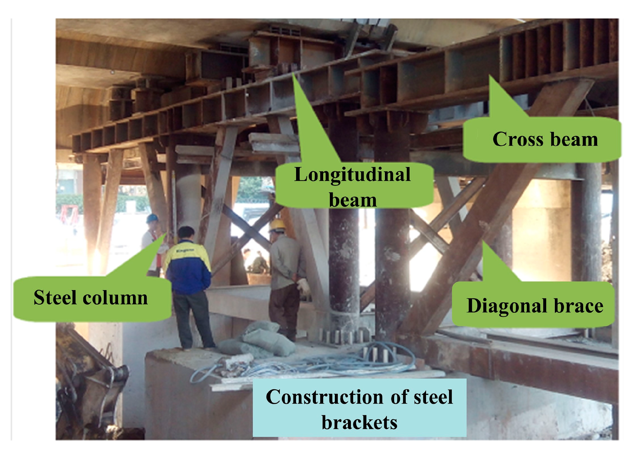
The temporary steel bracket (Figure 11) is composed of steel columns and a support system, whose composition is as follows from bottom to top: φ30 cm steel pipe pile foundation → temporary steel bracket bearing platform → φ40 (φ60) cm steel columns → H500 × 500 steel cross beams → H500 × 500 steel longitudinal beams → bearing.
The erection of steel brackets can be completed in two parts, the installation of steel columns and the construction of the support system.
The steel column is installed by the bracket. The components are moved to the vicinity of the installation site manually after they have been lifted by the crane and unloaded outside the projection range of the bridge deck. After erecting the bracket above it and placing the crossbeam to hang the lifting zipper pulley, it will be straightened and welded with the pre-built parts of the foundation.
The installation of the support system is based on the bottom-to-top method. The procedure of transverse support erection is as follows: constructing the steel columns → erecting the bottom connecting beams → erecting the connecting beams at the top of the steel columns → linking the inclined bracing system between the steel columns. The steel bracing rods should be connected by continuous fillet welds, the weld size of which is 8 mm for the continuous beam bracing and 10 mm for the continuous rigid bracing.

5.1.3. Replacement Construction of the Bridge-Bearing Bracket

The center spacing of φ30 cm steel pipe piles is 0.7 m. The steel skeleton is welded on top of the steel pipe piles, which is coupled with the temporary steel bracket-bearing foundation as a whole. Pre-buried bolts are needed to fix the steel columns on the top surface of the temporary bracket foundation, and the steel columns are reinforced with longitudinal and horizontal rods to ensure stability. The flange is set at the top of the steel column for placing the crossbeams (vertical line direction) fixed by a block welded to the flange.
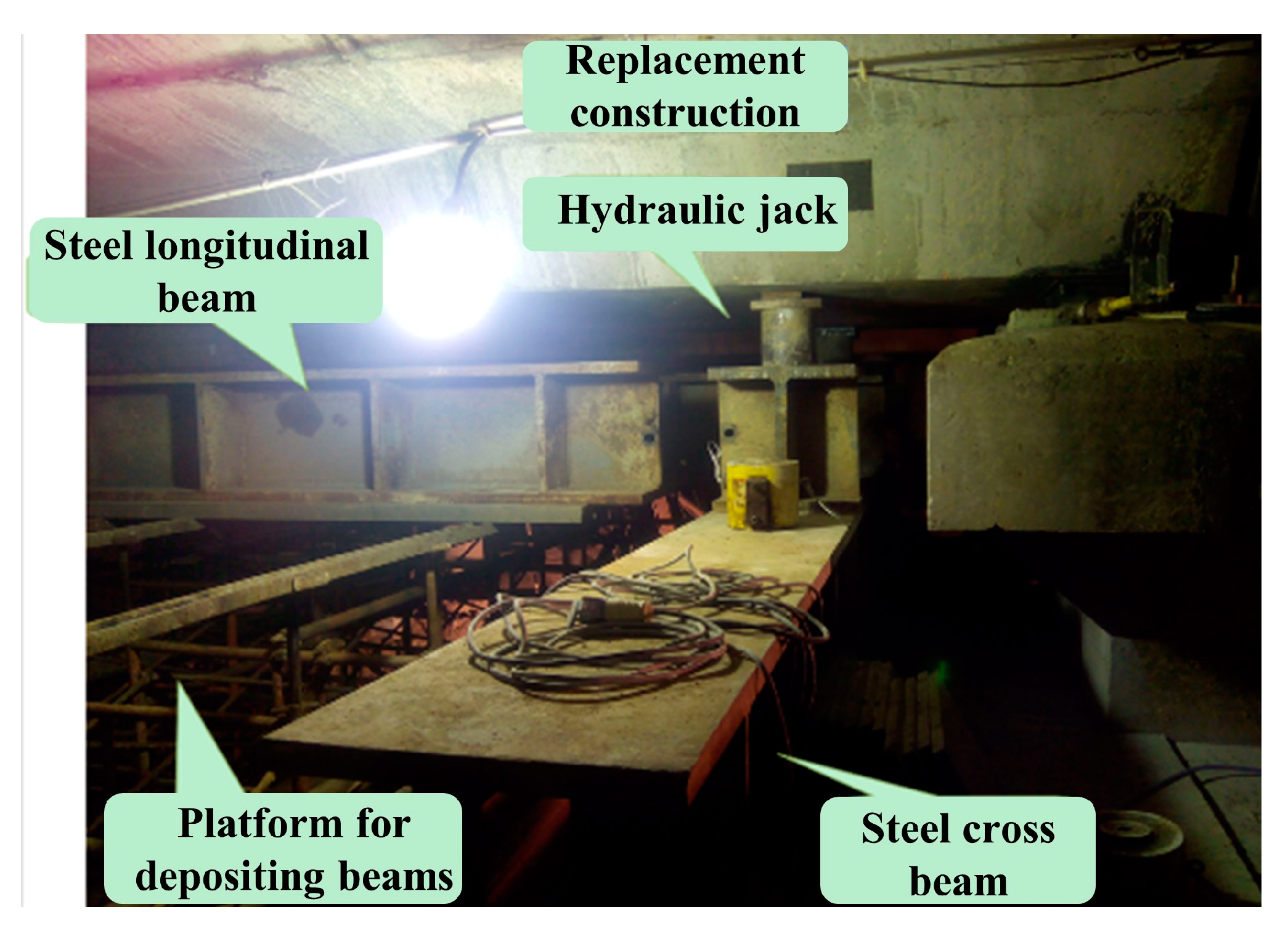
Temporary bearings are positioned on the bracket replacement longitudinal beam corresponding to the original bridge-bearing position to hold up the railway bridge. The original railway bridge bearing (or the same type as the original bearing) is chosen as the temporary bearing (Figure 12).
After each longitudinal beam has been installed, the gap between the bottom of the longitudinal beams and the old bridge piers should be stuffed with triangular wood before opening the line. After all the longitudinal beams are installed on one pier, the triangular wood at the bottom of the longitudinal beams should be removed so that each longitudinal beam can be stressed at the same time. After all the longitudinal beams of a pier are installed, remove the triangular wood from the bottom of the longitudinal beams, allowing each longitudinal beam to bear the force simultaneously.
In the process of bridge jacking, the force applied to the hydraulic jacks gradually increases to 1100 kN to hold up the railway bridge, which can ensure that the bridge will not fall or tilt during the cutting process, and then, the concrete block-cutting operation can be carried out.

5.1.4. Demolition of Old Bridge Piers and Bearings

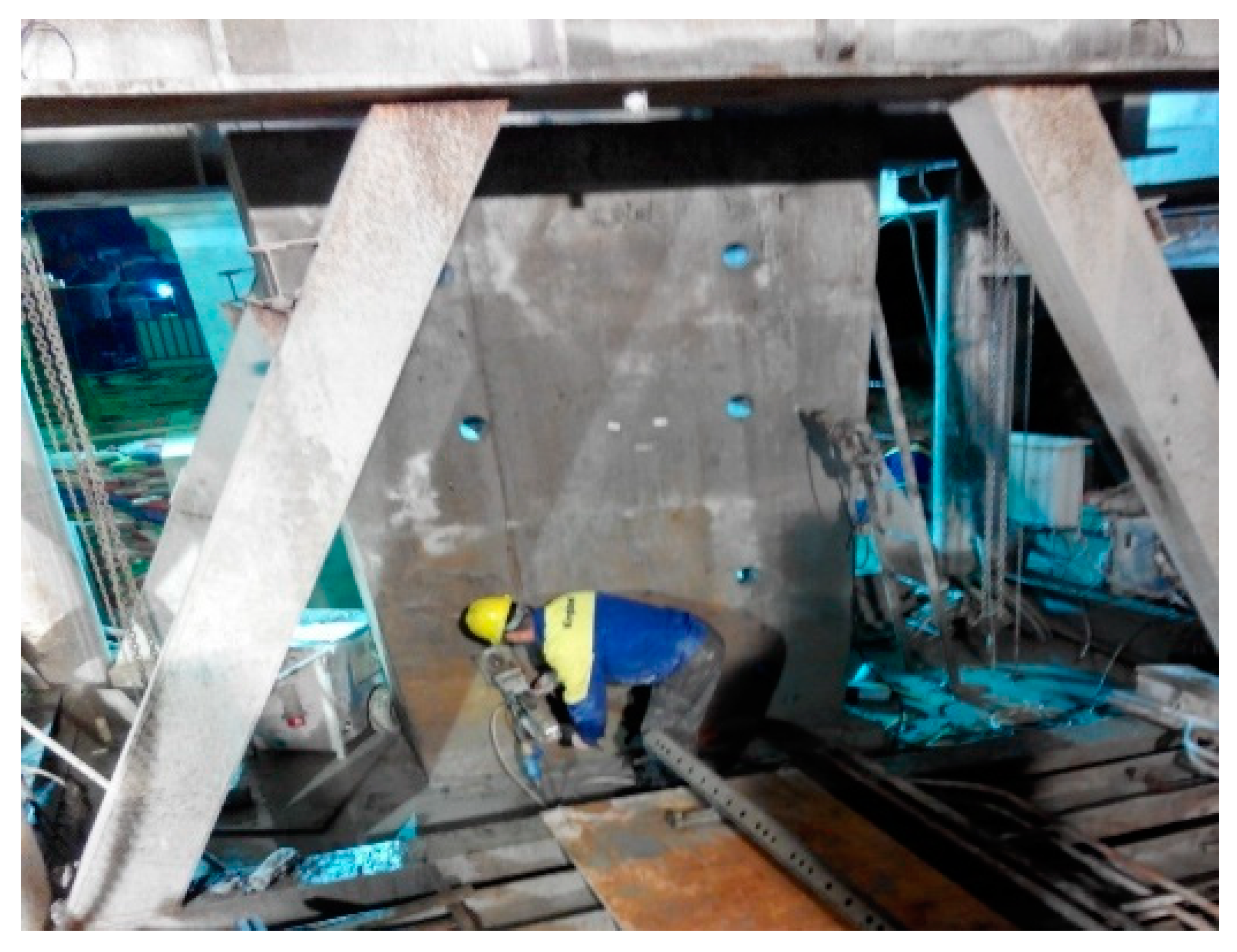
The support will transfer all the load to the steel columns through the bracket replacement longitudinal beams and cross beams after the steel bracket has been entirely assembled, and then, the load is transmitted to the bracket steel pipe piles through the bracket bearing platform. By this time, the old piers and bearings will no longer be subjected to the upper load, allowing for the removal of piers and bearings in slow time outside the blocking point (Figure 13).

5.1.5. Newly Constructed Piers and Abutments

Tie the bearing reinforcement, pour concrete, and rebuild the foundation of the bridge pier bearings according to the design requirements after excavating the foundation pit of the new bridge pier bearings (Figure 14). The bracket replacement steel longitudinal beams are embedded in the new pier cap, becoming a part of the new pier columns, and the temporary steel bracket is removed after the reconstruction of the new piers.

5.2. Problems and Solutions of In Situ Replacement Construction

5.2.1. Narrow Operating Space

The construction operation is relatively difficult due to the limited space for installing bearing bracket replacement steel beams, removing existing piers, and transiting operations. Part of the space in the pier cap concrete of the new bridge is occupied by the support bracket replacement steel beams. To ensure normal railway traffic, the support bracket replacement steel beams will be cast in the new pier cap concrete of the bridge to form a permanent structural system.
The above negative conditions are analyzed in detail and overcome by implementing special technical measures, such as arranging the replacement construction operations in accordance with the railway blocking conditions, decomposing the steps of cutting the concrete of the existing pier caps, wearing beams, and reinforcing to guarantee that the entire blocking operation is carried out in an orderly manner; increasing the concrete strength level of the new piers minimizes the impact caused by train vibration.

5.2.2. Construction of Steel Pipe Piles Encountering Underground Obstacles

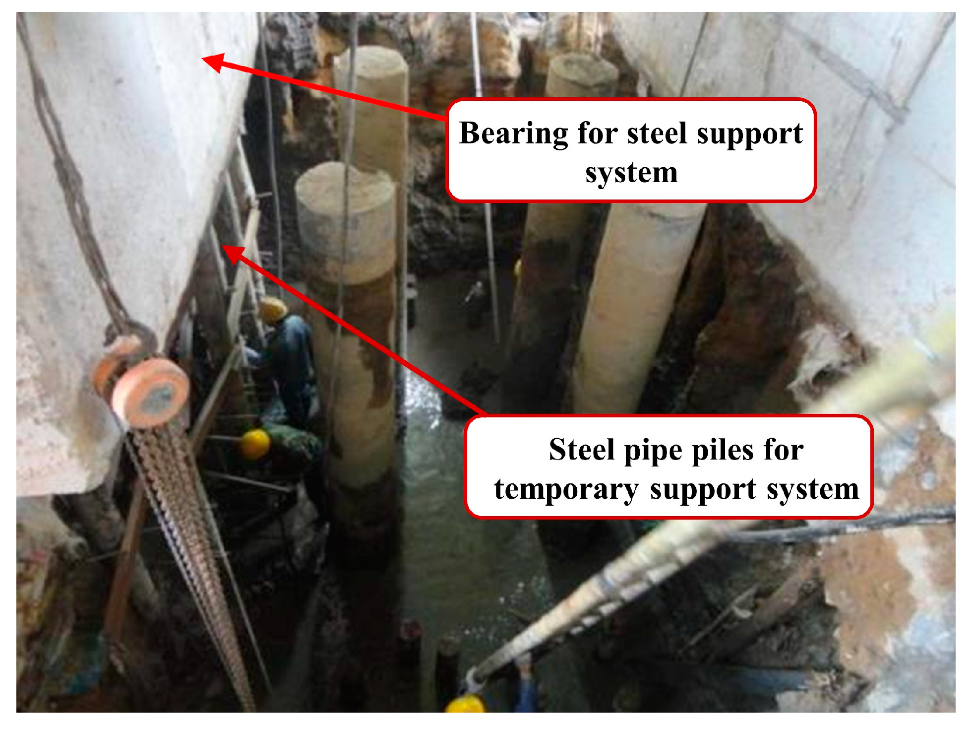
The underground situation is rather complicated due to the underlying obstacles encountered in the location of the steel pipe piles on the river side of the construction line, which leads to the inability to drive piles despite various attempts at the site. After reporting to the design unit and obtaining consent, the steel pipe piles on the south and north sides of the bearing platforms are canceled and replaced with the temporary, braced-steel pipe piles on the east and west sides in equal numbers (Figure 15), and the final hole elevation of the braced steel pipe piles and the reinforced steel pipe piles of the bearing platform is the same, which means that the bearing capacity of the piles is identical.
The reinforcement program of 4# pier bearing in line I is modified as follows: firstly, anchoring 4 temporary bracket steel pipe piles on each side of the east and west sides into the new bearing (Figure 16); pouring a new bearing, which measures 5.2 m (long) × 3.685 m (width) × 2 m (height); then, when the entire replacement construction is accomplished, remove the steel brackets from lines II and IV while still retaining the steel brackets in line I after the pier cap concrete has reached the design strength and the pier force has been restored. After that, the 4 steel pipe piles in the second row of the east and west sides will be cut out; the new 4# pier bearing in line I will then be widened and reinforced by means of enlarging 70 cm on each of the east and west sides and anchoring 8 steel pipe piles into it. Finally, backfill the pit and then remove the steel support of line I after the concrete in the widened portion of the bearing platform reaches the design strength.
The reinforcement program of the pier bearing in line IV 5# is modified as follows: Anchor 12 temporary bracket steel pipe piles on each side of the east and west sides into the new bearing, pouring a new bearing, which measures 8.4 m (long) × 5.3 m (width) × 2 m (height). Backfill the pit and then remove the steel support of line IV after the concrete in the widened portion of the bearing platform reaches the design strength.

5.2.3. Negative Impact on Other Structural Members

Demolition of old bridge piers and bearings is a comprehensive and systematic project, which could have a negative impact on other structural members due to the influencing impact force. In order to minimize the negative impact on the structure, the monitoring of the overall bridge form, structural displacement, internal forces at important nodes, and foundation settlement are key steps to ensure that the construction process is carried out safely.
The controlling of the displacement includes two stages, during the construction process and after the construction is completed. The former is to ensure that the displacement value is within the controllable range in strict accordance with the relevant requirements of the drawings and specifications during the construction process. The latter is to monitor whether the displacement will exceed the limit value after the construction is finished to ensure the safety of the bridge.
In terms of stress, control the stress of each structure during the construction process, monitor the local stress at the most unfavorable stress location, and understand its stress characteristics through the stress changes at the monitoring points.

6. Conclusions

To study the stability and safety of the steel support system for the demolition and reconstruction of the bridge pier bearing, the deformation and stress of the components under the trainload are analyzed, and the detailed presentation of the on-site construction cases, the following conclusions are obtained:
(1)
The stress and deformation of the main components of the steel bracket system meet the design requirements in each load condition, which means the safety and stability of the structure can be guaranteed;
(2)
For the stress and displacement distribution of the steel pipe pile under the trainload, the maximum stress appears at the bottom of the pile, while the maximum displacement appears at the top of the pile, and the magnitude of stress and displacement of the steel pipe pile decreases from the area of the trainload to both sides;
(3)
The greater the distance between the two intersection points of the longitudinal beam and its supporting crossbeams below, the larger the deflection of the longitudinal beam above it;
(4)
Due to the presence of the middle-span steel column, the overall stiffness of the supporting structure under line I and line II is higher than that under line IV;
(5)
The railway bridge-bearing in situ replacement construction plan has little impact on the existing railway bridge girders, and the steel bracket is simple in force form, but there are also corresponding problems in the process of construction operations that must be addressed by applying various safeguard measures to maximize the superiority of this construction plan.

Author Contributions

Conceptualization, P.P. and W.C.; funding acquisition, W.C.; methodology, P.P.; software, W.C. and P.W.; validation, P.P. and P.W.; formal analysis: P.W.; investigation: P.P.; visualization: W.C.; writing—original draft, P.W.; writing—review and editing, W.C. All authors have read and agreed to the published version of the manuscript.

Funding

This work was supported by the Natural Science Foundation of Hunan Province [grant number 2022JJ30715].

Institutional Review Board Statement

Not applicable.

Informed Consent Statement

Not applicable.

Data Availability Statement

The data presented in this study may be available on reasonable request from the corresponding author.

Conflicts of Interest

The authors declare no conflict of interest.

References

  1. Cook, W.; Paul, J.B.; Marvin, W.H. Bridge failure rate. J. Perform. Constr. Facil. 2013, 29, 04014080. [Google Scholar] [CrossRef]
  2. Mitoulis, S.A.; Argyroudis, S.A.; Loli, M.; Imam, B. Restoration models for quantifying flood resilience of bridges. Eng. Struct. 2021, 238, 112180. [Google Scholar] [CrossRef]
  3. Pejović, J.; Serdar, N.; Pejović, R. Damage assessment of road bridges caused by extreme streamflow in Montenegro: Reconstruction and structural upgrading. Buildings 2022, 12, 810. [Google Scholar] [CrossRef]
  4. Yuan, Z.W. Study on reconstruction technology for river-crossing multi-span bridge on railway operating line. Railw. Constr. Technol. 2019, 5, 56–59+89. (In Chinese) [Google Scholar]
  5. Wang, J. Application of bridge demolition technique in reconstruction and expansion engineering of expressway. Transp. Res. 2014, 42, 156–159. (In Chinese) [Google Scholar] [CrossRef]
  6. Deng, D.Y.; Zhang, X.Q.; Chen, Z.; Yang, G.F.; Lu, J.X. Study on force of steel bracket for construction of large span and wide steel box girder. IOP Conf. Ser. Mat. Sci. Eng. 2019, 490, 032013. [Google Scholar] [CrossRef]
  7. Horyl, P.; Šňupárek, R. Behaviour of steel arch supports under dynamic effects of rockbursts. Min. Technol. 2007, 116, 119–128. [Google Scholar] [CrossRef]
  8. Bobet, A.; Yu, H.T. Full stress and displacement fields for steel-lined deep pressure tunnels in transversely anisotropic rock. Tunn. Undergr. Space Technol. 2016, 56, 125–135. [Google Scholar] [CrossRef] [Green Version]
  9. Rodríguez, R.; Díaz-Aguado, M.B. Deduction and use of an analytical expression for the characteristic curve of a support based on yielding steel ribs. Tunn. Undergr. Space Technol. 2013, 33, 159–170. [Google Scholar] [CrossRef]
  10. Khalymendyk, I.; Baryshnikov, A. The mechanism of roadway deformation in conditions of laminated rocks. J. Sustain. Min. 2018, 17, 41–47. [Google Scholar] [CrossRef]
  11. Rotkegel, M.; Bock, S. Impact of bearing plates dimensions on interaction of mine workings support and rock mass. J. Sustain. Min. 2015, 14, 12–20. [Google Scholar] [CrossRef] [Green Version]
  12. Zang, D.S.; Li, A.Q. Study on concrete-filled steel tube supports. Chin. J. Geotech. Eng. 2001, 23, 342–344. (In Chinese) [Google Scholar]
  13. Zang, D.S.; Wei, L. Research and lab test of steel tube concrete support. Mine Constr. Technol. 2001, 6, 25–28. (In Chinese) [Google Scholar]
  14. Huang, W.P.; Yuan, Q.; Tan, Y.L.; Wang, J.; Liu, G.L.; Qu, G.L.; Li, C. An innovative support technology employing a concrete-filled steel tubular structure for a 1000-m-deep roadway in a high in situ stress field. Tunn. Undergr. Space Technol. 2018, 73, 26–36. [Google Scholar] [CrossRef]
  15. Zhang, J.P.; Liu, L.M.; Cao, J.Z.; Yan, X.; Zhang, F.T. Mechanism and application of concrete-filled steel tubular support in deep and high stress roadway. Constr. Build. Mater. 2018, 186, 233–246. [Google Scholar] [CrossRef]
  16. Fu, M.Z.; Liang, Y.X.; Feng, Q.S.; Wu, B.T.; Tang, G.X. Research on the application of multi-source data analysis for bridge safety monitoring in the reconstruction and demolition process. Buildings 2022, 12, 1195. [Google Scholar] [CrossRef]
  17. Han, X.; Yang, D.Y.; Frangopol, D.M. Optimum maintenance of deteriorated steel bridges using corrosion resistant steel based on system reliability and life-cycle cost. Eng. Struct. 2021, 243, 112633. [Google Scholar] [CrossRef]
  18. Seyed, K.A.; Akbari, R.; Maalek, S.; Gharighoran, A. Assessment of design and retrofitting solutions on the progressive collapse of Hongqi Bridge. Shock Vib. 2020, 2020, 4932721. [Google Scholar] [CrossRef]
  19. Tazarv, M.; Sjurseth, T.; Greeneway, E.; Hart, K.; LaVoy, M.; Wehbe, N. Experimental studies on seismic performance of mechanically spliced precast bridge columns. J. Bridge Eng. 2022, 27, 0001948. [Google Scholar] [CrossRef]
  20. Mansouri, S.; Kontoni, D.P.N.; Pouraminian, M. The effects of the duration, intensity and magnitude of far-fault earthquakes on the seismic response of RC bridges retrofitted with seismic bearings. Adv. Bridge Eng. 2022, 3, 19. [Google Scholar] [CrossRef]
  21. Huang, Q.; Wu, X.G.; Zhang, Y.F.; Ma, M. Proposed new analytical method of tower load in large-span arch bridge cable lifting construction. Appl. Sci. 2022, 12, 9373. [Google Scholar] [CrossRef]
  22. Li, Q.F.; Zhang, T.J. Research on the reliability of bridge structure construction process system based on copula theory. Appl. Sci. 2022, 12, 8137. [Google Scholar] [CrossRef]
  23. Tan, S.Y. Study on Vibration Transfer Characteristics and Structure Selection of Railway Track in Active Fault Zone Tunnels. Master’s Thesis, Beijing Jiaotong University, Beijing, China, 2017. (In Chinese). [Google Scholar]
  24. Qi, W.; Cao, Y.; Zhao, Z.H.; Mo, H.Y. Research on the influence of track gauge on stress characteristics of track structure. Railw. Eng. 2020, 60, 131–134. (In Chinese) [Google Scholar]
  25. Galvín, P.; François, S.; Schevenels, M.; Bongini, E.; Degrande, G.; Lombaert, G. A 2.5D coupled FE-BE model for the prediction of railway induced vibrations. Soil Dyn. Earthq. Eng. 2010, 30, 1500–1512. [Google Scholar] [CrossRef] [Green Version]
  26. Costa, P.A.; Calçada, R.; Cardoso, A.S. Ballast mats for the reduction of railway traffic vibrations. Numerical study. Soil Dyn. Earthq. Eng. 2012, 42, 137–150. [Google Scholar] [CrossRef]
  27. Cai, X.P.; Tan, S.Y.; Shen, Y.P.; Cai, X.H. Dynamic analysis of laying elastic sleeper on ballast track in tunnel. J. China Railw. Soc. 2018, 40, 87–93. (In Chinese) [Google Scholar]
  28. Pan, L.; Xu, L.; Chen, X.M.; Zhu, Z.X. Curved ballasted track-vehicle dynamic interaction: Effects of curve radius and track structural nonlinearity. J. Comput. Nonlinear Dynam. 2021, 16, 071004. [Google Scholar] [CrossRef]
  29. Lee, J.; Oh, K.; Park, Y.; Choi, J. Study on the applicability of dynamic factor standards by comparison of spring constant based dynamic factor of ballasted and concrete track structures. Appl. Sci. 2020, 10, 8361. [Google Scholar] [CrossRef]
  30. Cai, X.P.; Zhong, Y.L.; Hao, X.C.; Zhang, Y.R.; Cui, R.X. Dynamic behavior of a polyurethane foam solidified ballasted track in a heavy haul railway tunnel. Adv. Struct. Eng. 2019, 22, 751–764. [Google Scholar] [CrossRef]
  31. Ministry of Housing and Urban-Rural Development of the People’s Republic of China. Standard for Design of Steel Structures, 1st ed.; China Architecture & Building Press: Beijing, China, 2018. (In Chinese)
Figure 1. Bridge pier and steel bracket system.
Applsci 13 07213 g001
Figure 2. Finite element model: (a) temporary steel support system; (b) superstructure.
Applsci 13 07213 g002
Figure 3. The bridge to be reconstructed.
Applsci 13 07213 g003
Figure 4. Single pile bearing capacity test: (a) preparation before testing; (b) testing in progress.
Applsci 13 07213 g004
Figure 5. The Q-S curve of static load test.
Applsci 13 07213 g005
Figure 6. Distribution of trainload.
Applsci 13 07213 g006
Figure 7. Diagram of working conditions.
Applsci 13 07213 g007
Figure 8. Cloud diagram of steel pipe pile: (a) stress in case 1 (Unit: Pa); (b) displacement in case 1 (Unit: m); (c) stress in case 2 (Unit: Pa); (d) displacement in case 2 (Unit: m); (e) stress in case 3 (Unit: Pa); (f) displacement in case 3 (Unit: m).
Applsci 13 07213 g008
Figure 9. Cloud diagram of bearing: (a) stress in case 1 (Unit: Pa); (b) displacement in case 1 (Unit: m); (c) stress in case 2 (Unit: Pa); (d) displacement in case 2 (Unit: m); (e) stress in case 3 (Unit: Pa); (f) displacement in case 3 (Unit: m).
Applsci 13 07213 g009
Figure 10. Cloud diagram of bridge and track structure: (a) the region with a larger concentration of stress; (Unit: Pa) (b) Displacement in case 1 (Unit: m).
Applsci 13 07213 g010
Figure 11. Construction of steel support.
Applsci 13 07213 g011
Figure 12. Replacement construction of longitudinal beams.
Applsci 13 07213 g012
Figure 13. Pier cutting.
Applsci 13 07213 g013
Figure 14. Reconstruction of abutments and piers.
Applsci 13 07213 g014
Figure 15. Construction of steel pipe piles.
Applsci 13 07213 g015
Figure 16. Connection process of steel pipe pile and bearing.
Applsci 13 07213 g016
Table 1. Parameters of superstructure and temporary support system.
ComponentsElastic Modulus (MPa)Density (kg·m−3)Poisson’s Ratio
Rail210,00078000.3
Sleeper36,50025000.2
Ballast bed13018000.3
Box girder34,50025000.2
Supporting rods210,00078000.3
Bearing30,00023600.2
Table 2. Soil mechanics parameters.
Soil LayersThickness of Layers (m)Young Modulus (MPa)Poisson’s RationDensity (kg·m−3)Cohesion
(kPa)
Angle of
Internal
Friction (°)
Sand0.9220.3815204021
Silt3.875240.3615204226
Siltstone7.875260.3415603631
Silty clay7.35260.3515604535
Table 3. Concentrated force at temporary support.
Working Condition R 1   ( N ) R 2   ( N ) R 1   +   R 2   ( N )
1   704   ×   10 3   434   ×   10 3   1138   ×   10 3
2   798   ×   10 3   352   ×   10 3   1150   ×   10 3
3   633   ×   10 3   483   ×   10 3   1116   ×   10 3
4 599   ×   10 3 483   ×   10 3 1082   ×   10 3
Table 4. Maximum stress of each component in steel support system.
ComponentsMaximum Stress (MPa)
Case 1Case 2Case 3
Supporting longitudinal beam73.6273.8268.69
Supporting cross beam29.0918.7129.79
Diagonal brace81.9789.3588.01
Cross linkage78.9280.3385.60
Longitudinal linkage30.0135.5330.38
Side-span steel column23.4820.3415.33
Middle-span steel column8.999.053.18
Table 5. Deflection of longitudinal beam and cross beam.
Maximum Deflection (mm)Case 1Case 2Case 3
Longitudinal beam1.031.172.13
Cross beam0.970.972.05
Table 6. Maximum displacement and stress of each component.
IndicatorsDisplacement
(mm)
Tensile Stress (MPa)Compressive Stress (MPa)
RailsSleepersBallast BedBox GirderRailsRailsBallast Bed
Condition 14.2734.4454.4344.40438.2745.340.121
Condition 24.2974.6534.6374.64238.2945.300.123
Condition 37.0577.2337.2257.34339.1845.410.177
Disclaimer/Publisher’s Note: The statements, opinions and data contained in all publications are solely those of the individual author(s) and contributor(s) and not of MDPI and/or the editor(s). MDPI and/or the editor(s) disclaim responsibility for any injury to people or property resulting from any ideas, methods, instructions or products referred to in the content.