Article

Modification of Nonlinear Controller for Asymmetric Marine Vehicles Moving in Horizontal Plane

by
Przemyslaw Herman
Institute of Automatic Control and Robotics, Poznan University of Technology, ul. Piotrowo 3a, 60-965 Poznan, Poland
Appl. Sci. 2023, 13(12), 7242; https://doi.org/10.3390/app13127242
Submission received: 22 May 2023 / Revised: 9 June 2023 / Accepted: 15 June 2023 / Published: 17 June 2023
(This article belongs to the Special Issue Design and Implementation of Underwater Vehicles)

Abstract

:
This paper considers a trajectory-tracking control algorithm for underactuated marine vehicles moving horizontally in which the current in the North-East-Down frame is constant. This algorithm is a modification of a control scheme based on the input-output feedback linearization method for which the application condition is that the vehicle is symmetric with respect to the left and right sides. The proposed control scheme can be applied to a fully asymmetric model, and, therefore, the geometric center can be different from the center of mass in both the longitudinal and lateral directions. A velocity transformation to generalized vehicle equations of motion was used to develop a suitable controller. Theoretical considerations were supported by simulation tests performed for a model with 3 degrees of freedom, in which the performance of the proposed algorithm was compared with that of the original algorithm and the selected control scheme based on a combination of backstepping and integral sliding mode control approaches.

1. Introduction

Non-holonomic systems, such as autonomous underwater vehicles (AUVs) among others, are difficult to control because of their underactuated nature. In general, underwater vehicle models are strongly nonlinear, contain mechanical couplings, and are described by 6 DOF (degrees of freedom), and the equations of motion depend on many factors, as shown in, for example, [1,2]. Moreover, as is known from the literature, many control algorithms have been developed for fully actuated marine vehicles. One of the important issues for control is tracking a desired trajectory.
In the case of underactuated marine vehicles, building a tracking controller is a significant challenge. Although there are algorithms for models with 6 DOF, for example, [3,4], there are many controllers for models that are simplified from a mechanical point of view. One possible simplification is to use a diagonal inertia matrix as in [5,6]. Another increasingly common simplification is to design the controller for a 5 DOF model with a diagonal inertia matrix, as in [7,8,9].
One of the significant problems that make it difficult to control a marine vehicle is its asymmetry. This occurs when the center of mass does not coincide with the geometric center. This results in additional inertial forces that must be reduced during the controller operation. This problem becomes even more important when the vehicle is underactuated because not all control signals are then available. For this reason, the control algorithm should include additional components to reduce unwanted effects due to the presence of asymmetry. This means that, in the simplest model, when the inertia matrix is diagonal, the control algorithm must guarantee tracking of the desired trajectory with imprecise knowledge of the model parameters.
Because this work addresses the issue of tracking control for underactuated 3 DOF underwater vehicles moving in the horizontal plane, it is worth reviewing publications on this type of object.
Designing controllers for underactuated vehicles is a complex process when the dynamics model is complicated, hence the need to simplify the model. There are many trajectory-tracking strategies described in the literature where the inertia matrix is diagonal. They concern either underwater vehicles in planar motion or surface vehicles. Some control schemes use the Lyapunov theory, as shown in [10,11]. Another solution to the trajectory-tracking problem is to use sliding mode control (SMC) methods [12,13]. In addition, the prescribed performance method has been applied as a control strategy [14,15]. Other important solutions to the trajectory-tracking problem are control schemes based on neural networks (NN), e.g., in [16], or fuzzy logic [17]. There are also many other algorithms for trajectory tracking, such as terminal sliding mode control (TSMC) [18], output feedback control [19] and the linear algebra approach [20]. In order to achieve good performance of control algorithms, combinations of different methods are often proposed, e.g., the backstepping and Lyapunov methods [21], backstepping and SMC (plus Lyapunov stability theory) [22,23], NN and SMC [24,25], NN and SMC plus backstepping [26,27]), backstepping and neural network plus low-frequency techniques [28], event-triggered tracking control with prescribed performance using radial basis function NN (RBFNN) [29], and strategy based on virtual control points and RBFNN [30]. A control scheme which is a combination of an extended state observer (ESO) and a super-twisting second-order sliding mode controller was proposed in [31]. Mu et al. [32] developed a tracking control scheme based on a combination of prescribed performance and the Lyapunov logarithmic barrier function. Event-triggered composite learning using an NN controller was considered in [33]. Taking into account the inertia matrix, it can be seen that most control methods are designed for a vehicle described by a simplified model with a diagonal matrix. This approach results in the algorithms being less complicated from a mathematical point of view and easier to implement. However, information on vehicle dynamics is often less accurate because the algorithm should overcome any model inaccuracies in the control process. Of course, the approach based on the assumption of negligible couplings makes sense if the vehicle is indeed exactly balanced or if it is justified that the couplings have small (negligible) values. However, such conditions are not always met and then the simplified control algorithm may not be effective enough or its performance will be worse.
If the asymmetry of the vehicle is so significant that it cannot be ignored, then control strategies are usually proposed using a model with a symmetric inertia matrix but assuming symmetry with respect to the right and left sides. Control schemes designed for such asymmetric underactuated marine vehicles moving horizontally are less common than control algorithms with a diagonal inertia matrix. Various control algorithms are available for the model in which the vehicle is symmetric in its longitudinal plane. For example, an integral backstepping algorithm was proposed in [34] for tracking the trajectory in the presence of ocean current disturbance. The combination of a backstepping technique, cascade analysis, and the Lypunov approach for full state regulation of surface vehicles can be found in [35], and the combination of the Lyapunov direct method with backstepping control in [36,37]. In [38], a control scheme based on the input-output feedback linearization method and usage of the position point of the hand was presented. A trajectory-tracking algorithm for planar under-actuated vehicles that utilize sliding mode control was described in [39]. The design of an improved line of sight (LOS) using an adaptive terminal sliding mode controller was addressed in [40]. In [41], an FUO (finite-time uncertainty observer) was developed in order to enable the separation principle in the algorithm and synthesis of the observer’s perspective, making it possible to accurately control the trajectory tracking.
Controlling trajectory tracking by developing an accurate control method in a newly defined polar coordinate system moving along a path (PMPCS) was proposed in [42]. The application of neural networks in control strategies was reported, for example, in [43,44]. An adaptive control algorithm with prescribed performance for underactuated surface vehicle trajectory tracking was developed in [45], while, in [46], this method was supported by neural networks. An approach to the tracking control problem based on the prescribed performance function and quantized feedback signals was described in [47]. For a fully asymmetric vehicle, an algorithm based on a combination of backstepping and integral SMC was proposed in [48]. A brief overview of methods to solve the trajectory-tracking problem for vehicle model asymmetry and disturbances is given in Table 1. In the table, the sign + indicates a positive answer, while − indicates a negative answer. It may be noted that, in the case of a diagonal inertia matrix (symmetric vehicle), variable disturbance models are used, which should reduce the effect of the environment and modeling inaccuracies on the performance of the controller. However, even when partial asymmetry is assumed, functions representing disturbances are usually introduced in addition.
This paper is concerned with using one of the algorithms (in modified form after velocity transformation) to track a desired trajectory of a 3 DOF vehicle model. In order to perform the trajectory-tracking task, a controller expressed in terms of some quasi-velocities (QV) was used. The proposed scheme uses the idea discussed in [38]. This study does not use a combination of different approaches that can make it difficult to use QV, so it was thought appropriate for the considered control task.
However, the difference between the proposed controller and those mentioned above is that here it is assumed that the vehicle is not symmetrical about the axes of longitudinal and lateral motion. Moreover, introducing a description of the vehicle dynamics with the use of quasi-velocities is necessary to carry out the task of trajectory tracking because it enables first-order differential equations to be obtained. Such a description causes the inertia matrix to be diagonal and the obtained quasi-accelerations to be independent. The QV adapted here are referred to in [49] as generalized velocity components (GVC), and were applied for mechanical systems. In the past, they were also used to control fully actuated underwater vehicles [50,51]. Unfortunately, a drawback of the proposed approach to the control task is a failure to show the stability of the entire system. Instead, we show how the dynamics equations used can be transformed to the form considered in the cited work. Selected simulations on 3 DOF models of two vehicles moving horizontally with three trajectories demonstrated the effectiveness of the application. However, in the tests, it turned out that the idea of control is practical for various models of underwater vehicles with different desired trajectories.
The contributions of this work can be summarized as follows:
(1)
Decomposition of the inertia matrix enabling description of the use of velocity transformation for an underactuated underwater vehicle moving in the horizontal plane, obtaining diagonal equations of motion, and testing of the modified control algorithm.
(2)
Showing some of the information available from the trajectory-tracking controller when a dynamic description containing quasi-velocities (QV) is used.
(3)
Proposal of an algorithm for trajectory tracking in horizontal motion when the center of mass lies outside both axes of symmetry of the vehicle. This controller is generalized in the sense that the previously known controllers from [38,52] are special cases of it and apply only when the center of mass is shifted in the longitudinal direction. In contrast, this scheme also considers shift in the center of mass in the lateral direction. A simulation test of the modified control algorithm was performed for two models of different vehicles and three desired trajectories based on intuitive selection of controller parameters.
Compared to [52], this paper is different in the following ways:
(1)
First, the algorithm presented is applicable to vehicles whose center of mass lies outside the coordinate axes and is not symmetrical on the longitudinal axis.
(2)
Second, the theoretical contribution is that the vehicle dynamics model is more realistic and this has been taken into account in the control algorithm.
(3)
Third, the controller contains more dynamic couplings due to the more complex dynamic model. Therefore, it is possible to assess their influence on the movement of the vehicle along the selected desired trajectory.
(4)
Fourth, a motion analysis for the cycloid–like trajectory is included in the simulation study, which provides a deeper understanding of the vehicle dynamics using the proposed controller. Instead of a sine trajectory, a sine-cosine trajectory was applied. In addition, quantities that are crucial for coupling evaluation are added.
Section 2 describes the marine vehicle model and the transformed equations of motion in terms of the quasi-velocities. Section 3 describes the modified tracking controller. In Section 4, simulations are shown for two different underwater vehicles and three desired trajectories. In Section 5, the conclusions are presented.

2. Marine Vehicle Model

A model of the considered planar vehicle in the North-East-Down (NED) frame is shown in Figure 1.
In this frame, the position and the orientation of the vehicle are represented by the vector η = [ x , y , ψ ] T . The velocities in the body frame are ν = [ u , v , r ] T (the surge velocity, the sway velocity, and the yaw rate, respectively). Moreover, the vector V = [ V x , V y , 0 ] T describes the ocean current in the NED frame. In the body frame, the ocean current vector is expressed as ν c = R T ( ψ ) V . The model of motion of an AUV moving horizontally is given as [1,2]:
η ˙ = R ( ψ ) ν r + V ,
M ν ˙ r + C ( ν r ) ν r + D ν r = τ ,
where ν r = [ u r , v r , r ] T = ν ν c is the vector of relative velocities in the body frame, D means the linear damping coefficients matrix, and τ is the control vector containing the applied force along the surge motion and the applied torque around the z axis. The matrices in the above equations are:
R ( ψ ) = cos ψ sin ψ 0 sin ψ cos ψ 0 0 0 1 , M = m 11 0 m 13 0 m 22 m 23 m 13 m 23 m 33 , C ( ν r ) = 0 0 c 13 0 0 c 23 c 13 c 23 0 , D = d 11 0 d 13 0 d 22 d 23 d 31 d 32 d 33 , τ = τ u 0 τ r .
The elements of the matrices are as follows: m 11 = m X u ˙ , m 22 = m Y v ˙ , m 13 = m 31 = m y g X r ˙ , m 23 = m 32 = m x g Y r ˙ , m 33 = J z N r ˙ , c 13 = m 22 v r m 23 r , c 23 = m 11 u r m 13 r , and d 11 , d 22 , d 23 , d 32 , and d 33 are constant hydrodynamic damping coefficients. The equation replacing (1) can be written in the following form:
x ˙ y ˙ ψ ˙ = u r cos ψ v r sin ψ + V x u r sin ψ + v r cos ψ + V y r .

2.1. Transformed Equations of Motion

If the inertia matrix M is symmetric, then it is possible to decompose it, e.g., using the method given in [49]. This approach was successfully applied for marine vehicles, for example, in [50,51]. The decomposition leads to M = Υ T N Υ 1 and a diagonal matrix N = Υ T M Υ is obtained. As a result, instead of (2), one has:
η ˙ = R ( ψ ) ν r + V , ν r = Υ ζ ,
ζ ˙ + N 1 Υ T C ( ν r ) ν r + N 1 Υ T D ν r = N 1 Υ T τ ,
where ζ = [ ζ 1 , ζ 2 , ζ 3 ] T , with:
Υ = 1 0 Υ 13 0 1 Υ 23 0 0 1 , N = d i a g { N 1 , N 2 , N 3 } ,
where N 1 = m 11 , N 2 = m 22 N 3 = m 33 ( m 13 2 / m 11 ) ( m 23 2 / m 22 ) , Υ 13 = ( m 13 / m 11 ) , Υ 23 = ( m 23 / m 22 ) , ζ 1 = u r Υ 13 r , ζ 2 = v r Υ 23 r , ζ 3 = r which means that v r ζ 2 because u r = ζ 1 + Υ 13 ζ 3 and v r = ζ 2 + Υ 23 ζ 3 . Moreover, N 1 B f = [ τ u , 0 , τ r + Υ 13 τ u ] T = [ τ ξ u , 0 , τ ξ r ] T .
Remark 1.
The QV ζ 1 , ζ 2 , and ζ 3 have a physical sense. They can be understood as a speed disturbance due to dynamic couplings in the vehicle, namely, ζ 1 = u r + Δ u r , ζ 2 = v r + Δ v r , ζ 3 = r .
The equations replacing (1) and (2) are as follows:
x ˙ = ( ζ 1 + Υ 13 ζ 3 ) cos ψ ( ζ 2 + Υ 23 ζ 3 ) sin ψ + V x ,
y ˙ = ( ζ 1 + Υ 13 ζ 3 ) sin ψ + ( ζ 2 + Υ 23 ζ 3 ) cos ψ + V y ,
ψ ˙ = ζ 3 ,
ζ ˙ 1 = F 1 ( ζ ) + τ ξ u ,
ζ ˙ 2 = F 2 ( ζ )
ζ ˙ 3 = F 3 ( ζ ) + τ ξ r ,
where:
F 1 ( ζ ) = N 1 1 c 13 ( ζ ) ζ 3 + d 11 ( ζ 1 + Υ 13 ζ 3 ) + d 13 ζ 3 ,
F 2 ( ζ ) = N 2 1 c 23 ( ζ ) ζ 3 + d 22 ( ζ 2 + Υ 23 ζ 3 ) + d 23 ζ 3 , F 3 ( ζ ) = N 3 1 ( c 13 ( ζ ) ( ζ 1 + Υ 13 ζ 3 ) + c 23 ( ζ ) ( ζ 2 + Υ 23 ζ 3 ) c 33 ( ζ ) ζ 3 ( Υ 13 d 11 + d 31 ) ( ζ 1 + Υ 13 ζ 3 ) ( Υ 23 d 22 + d 32 ) ( ζ 2 + Υ 23 ζ 3 )
( Υ 13 d 13 + Υ 23 d 23 + d 33 ) ζ 3 ) ,
and c 13 ( ζ ) = ( m 22 ( ζ 2 + Υ 23 ζ 3 ) + m 23 ζ 3 ) , c 23 ( ζ ) = m 11 ( ζ 1 + Υ 13 ζ 3 ) m 13 ζ 3 , c 33 ( ζ ) = Υ 13 c 13 ( ζ ) + Υ 23 c 23 ( ζ ) .
The change in coordinates after using the velocity transformation is applied. Therefore, in terms of the QV, one gets:
z 1 = ψ ,
z 2 = ζ 3 ,
ξ 1 = x + l cos ψ ,
ξ 2 = y + l sin ψ ,
ξ 3 = ( ζ 1 + Υ 13 ζ 3 ) cos ψ ( ζ 3 + Υ 23 ζ 3 ) sin ψ ζ 3 l sin ψ ,
ξ 4 = ( ζ 1 + Υ 13 ζ 3 ) sin ψ + ( ζ 3 + Υ 23 ζ 3 ) cos ψ + ζ 3 l cos ψ .
Moreover,
z ˙ 1 = z 2 ,
z ˙ 2 = F 3 ( ζ ) + τ ξ r * ,
ξ ˙ 1 ξ ˙ 2 = ξ 1 ξ 2 + V x V y ,
ξ ˙ 3 ξ ˙ 4 = F ξ 3 ( z 1 , ξ 3 , ξ 4 ) F ξ 4 ( z 1 , ξ 3 , ξ 4 ) + cos z 1 ( l + Υ 23 ) sin z 1 sin z 1 ( l + Υ 23 ) cos z 1 τ u * τ r * ,
where:
F ξ 3 ( · ) F ξ 4 ( · ) = cos ψ sin ψ sin ψ cos ψ F 1 ( ζ ) ζ 2 ζ 3 ( l + Υ 23 ) ζ 3 2 + Υ 13 F 3 ( ζ ) F 2 ( ζ ) + ( ζ 1 + Υ 13 ζ 3 ) ζ 3 + ( l + Υ 23 ) F 3 ( ζ ) .
Comment—Relationships with source description. The change in coordinates was defined in [38] as follows: z 1 , z 2 , ξ 1 , ξ 2 by (17)–(20), whereas the other is defined as:
ξ 3 = u r cos ψ v r sin ψ r l sin ψ ,
ξ 4 = u r sin ψ + v r cos ψ + r l cos ψ .
The Equations (17)–(22) represent the above variables in terms of QV.

2.2. Additional Information Obtained by Using QV

If QV is employed, then additional ones can be obtained that are not available in the classical equations of motion. The set of quantities and indexes was presented for fully actuated 6 DOF underwater vehicles, e.g., in [50,51]. However, in this paper, they are used to study the dynamics of a 3 DOF underactuated vehicle and at relative velocities. The following measures were adopted to evaluate the performance of the algorithm:
(1)
Norm of the matrix Υ 1 representing the normalized value of the couplings in the dynamic vehicle model. The matrix Υ is calculated from the symmetric matrix M and depends on the dynamic and geometric parameters.
(2)
The kinetic energy dissipated by each vector variable ζ (and its sum concerning the whole vehicle) following the formula: K = 1 2 ν r T M ν r = 1 2 ζ T N ζ = 1 2 i = 1 3 N i ζ i 2 = i = 1 3 K i .
(3)
The mean value of kinetic energy related to each variable and the sum of the mean kinetic energy: K m = m e a n ( K ) = i = 1 3 m e a n ( K i ) .
(4)
The distortion of each velocity due to couplings resulting from the formula: Δ ζ i = ζ i ν r i . The QV ζ i includes couplings between itself and the other velocities because ζ i = Υ i i 1 ν r i + j = i + 1 3 Υ i j 1 ν r j .

2.3. Relationship to Original Description of Dynamics

In order to compare the original description of the dynamics in [38] (where m 13 = 0 , d 13 = 0 , and d 31 = 0 ) and that presented here using the Equations (1)–(3), it is sufficient to perform a partial diagonalization of the inertia matrix, namely, by calculating:
Υ 1 = 1 0 Υ 13 0 1 0 0 0 1 , P = Υ 1 T M Υ 1 .
As a result, the equation of motion dynamics is as follows:
P κ ˙ r + C * ( ν r ) ν r + D * ν r = B * f ,
where κ r = [ u r Υ 13 r , v r , r ] T , which results from the relationship between the variables (cf. Appendix A). The matrices are of the form:
P = m 11 0 0 0 m 22 m 23 0 m 23 p 33 , C * ( ν r ) = 0 0 c 13 0 0 c 23 c 13 c 23 Υ 13 c 13   , D * = d 11 0 d 13 0 d 22 d 23 Υ 13 d 11 + d 31 d 32 Υ 13 d 13 + d 33   , B * = b 11 0 0 b 22 0 b 32 .
The new parameter used is: p 33 = m 33 ( m 13 2 / m 11 ) . Recalling again the source reference [38] and Υ 13 from Equation (7) (also applied in (30)), it may be observed that the only difference is due to the presence of Υ 13 . The equations of motion, such as those in the cited publication, will occur in the case where it is assumed that Υ 13 = 0 , that is, in the absence of the element m 13 .

3. Controller in Terms of Quasi-Velocities

3.1. Differences Compared to the Original Trajectory-Tracking Algorithm

The proposed algorithm is based on the control idea developed in [38]. However, since the QV controller does not meet some of the conditions of the original controller, it is necessary to refer to assumptions 1–8, i.e., (A1)–(A8) given in the reference work.
Assumptions (A1), (A3), (A4), (A7), (A8) remain unchanged. (A1) says that only surge, sway, and yaw are taken into account. In (A3), only the hydrodynamic damping is assumed to be linear. According to (A4), the ocean current in the inertial frame V = [ V x , V y ] T is non-rotational, constant, and bounded ( V m a x > 0 under condition ( V x 2 + V y 2 ) 1 / 2 V m a x ).
The desired trajectory, defined as Γ ( t ) = { ( ξ 1 d ( t ) , ξ 2 d ( t ) , ξ 3 d ( t ) , ξ 4 d ( t ) ) | t R + } with ξ ˙ 1 d = ξ 3 d , ξ ˙ 2 d = ξ 4 d , is considered. (A7) says that there are constant values for signal limitation (m-minimum value, M-maximum value), such that ξ 3 d ( t ) ξ 3 m , ξ 3 M , ξ 4 d ( t ) ξ 4 m , ξ 4 M , ξ ˙ 3 d ( t ) ξ ˙ 3 m , ξ ˙ 3 d M , ξ ˙ 4 d ( t ) ξ ˙ 4 d m , ξ ˙ 4 d M . According to (A8), the following total relative velocity is chosen U d = ( ξ r 3 d 2 + ξ r 4 d 2 ) 1 / 2 > 0 , where ξ r 3 d = ξ 3 d V x and ξ r 4 d = ξ 4 d V y . In addition, to overcome disturbances from ocean currents, the vehicle’s propulsion motors must provide sufficient power. Assumptions (A2), (A5), and (A6) have been modified.
Assumption (A2) of symmetry on the port and starboard sides is extended because, in the proposed approach, the vehicle may be asymmetric about two axes. The relationship between the model considered in [38] and in this work was discussed in Section 2.3. (A5) The body-fixed coordinate frame b is at a point ( x P * , 0 ) (the distance x P is defined from the center of gravity along the vehicle center line). The point ( x P * , 0 ) is understood as the pivot point, that is, such that M 1 B f = [ τ u , 0 , τ r ] T . However, Equation ((2)–) is slightly different from that in [38] due to the different location of the center of mass. According to the modification (A6), conditions Y 1 > 0 and Y 2 > 0 are satisfied (these quantities are calculated in Appendix A), which applies to the situation of unstable sway dynamics.
Formally, the control objective is as follows:
lim t ( ξ 1 ξ 1 d ( t ) ) = 0 , lim t ( ξ 2 ξ 2 d ( t ) ) = 0 , lim t ( ξ 3 ξ r 3 d ( t ) ) = 0 , lim t ( ξ 4 ξ r 4 d ( t ) ) = 0 .
Proposed quasi-velocity controller (QVC). To maintain the same idea of changing variables as in [38], it was assumed that u r = ξ 3 cos z 1 + ξ 4 sin z 1 , v r = ξ 3 sin z 1 + ξ 4 cos z 1 z 2 l , and r = z 2 . The change in input to linearize the external dynamics can be written as follows:
τ u * τ r * = cos ψ ( l + Υ 23 ) sin ψ sin ψ ( l + Υ 23 ) cos ψ 1 F ξ 3 ( z 1 , ξ 3 , ξ 4 ) + μ 1 F ξ 4 ( z 1 , ξ 3 , ξ 4 ) + μ 2 * .
The control input vector μ = [ μ 1 , μ 2 * ] T solves the problem under consideration, that is, tracking the desired trajectory Γ ( t ) .
Define Δ ξ 3 = ξ 3 ξ 3 d , Δ ξ 1 = ξ 1 ξ 1 d , Δ ξ 1 I = ξ 1 I ξ 1 d I , Δ ξ 4 = ξ 4 ξ 4 d , Δ ξ 2 = ξ 2 ξ 2 d , Δ ξ 2 I = ξ 2 I ξ 2 d I , where ξ i I = 0 t ξ i ( σ ) d σ , where i { 1 , 2 , 1 d , 2 d } are the integrals of signals ξ i I . Then, in the controller (34), there are two inputs μ 1 and μ 2 * , namely:
μ 1 = k v x Δ ξ 3 k p x Δ ξ 1 k I x Δ ξ 1 I + ξ ˙ 3 d ,
μ 2 * = k v y ( l + Υ 23 ) Δ ξ 4 k p y Δ ξ 2 k I y Δ ξ 2 I + ξ ˙ 4 d ,
where k v x , k v y , k p x , k p y , k I x , and k I y , which are positive real constant gains, are used. The first signal (35) is the same as in [38], but the second is different, which is key to completing the control task.
This algorithm guarantees the achievement of the control objectives (33). However, from the decomposition method used, it follows that τ u * = ( N 1 1 + N 3 1 Υ 13 2 ) τ u + N 3 1 Υ 13 τ r and τ r * = N 3 1 Υ 13 τ u + N 3 1 τ r . This relationship can be used for the input signals normalization and is given in the following form:
τ u τ r = s f N 1 N 1 Υ 13 N 1 Υ 13 N 3 + N 1 Υ 13 2 μ 1 μ 2 * ,
where s f means a scaling factor (a constant value). In addition, the following relationships arise from τ u = s f N 1 ( μ 1 Υ 13 μ 2 * ) and τ r = s f N 3 μ 2 * N 1 Υ 13 ( μ 1 Υ 13 μ 2 * ) . If the values N 1 and N 3 are too large or too small, the control signal becomes ineffective.
The benefit of such normalization is that the action of the control algorithm will be directly related to the dynamics of the vehicle. Note that, in [38], the control gains are selected without reference to the vehicle dynamics.
Comment. Theorem 1 of [38] is only partially satisfied for the control algorithm in terms of QV due to the different equations of motion. To relate this to the results of the original work, a revised theorem was proposed based on a vehicle model analogy. In the reference, the desired total relative velocity U d is defined. This quantity and its time derivative are limited, that is, U d U d m i n , U d m a x , and U ˙ d U ˙ d m i n , U ˙ d m a x .
Modified theorem. An underactuated marine vehicle is described by the model (A4)–(A6) and (A12)–(A17) (cf. Appendix A). The point of position of the hand is h = [ ξ 1 , ξ 2 ] T = [ x + l cos ψ , y + l sin ψ ] T (where [ x , y ] T is the position of the pivot point of the vehicle, l is a positive constant, and ψ is the yaw angle of the vehicle). Then, the velocity U d = ( ( ξ r 3 d 2 + ξ r 4 d 2 ) 2 ) 1 / 2 > 0 and ϕ 1 = arctan ( ξ r 4 d 2 / ξ r 3 d 2 ) , the crab angle (the angle between the vehicle track and the longitudinal axis of the vehicle), are defined. Provided that assumptions 1-8 (including their modifications) are met, and if:
0 < U d m a x < Y 2 / Y 1 ,
k v x , k v y , k p x , k p y , k I x , k I y > 0 ,
l > m a x { m 22 / m 23 , X 2 / Y 2 } ,
U ˙ d m a x 2 m i n { a ̲ ( d ̲ c ̲ ) , b } Y 1 U d m a x l + 2 Y 1 X 1 1 l , b = Y 2 + X 2 l ,
then, the controller described by Equation (34), where Υ 23 = 0 , and with new input signals (35) and (36), is guaranteed to achieve the control objectives (33). In the particular case, the relative velocities ( ξ 1 , ξ 2 , ξ 3 , ξ 4 ) tend globally exponentially to the corresponding set velocities ( ξ 1 d , ξ 2 d , ξ 3 d , ξ 4 d ), while ( z 1 , z 2 ) are only globally ultimately bounded. In addition, the steady-state values V ^ x , V ^ x of the integral variables provide estimates of the ocean current.
Comment. Condition Υ 23 = 0 is necessary due to the fact that only partial diagonalization is needed to take advantage of the similarity to the original method. The quantities X 1 , X 2 , Y 1 , Y 2 are determined from (A21). Moreover, the positive constants a ̲ , c ̲ , d ̲ are defined in [38].
Sketch of proof. Consider the relationships shown in Section 2.3 and the results shown in Appendix A, in particular the revised values of X 1 , X 2 , Y 1 , Y 2 . Using the similarity to the results shown in [38], the proof of the modified theorem would be analogous.

3.2. Advantages and Limitation of Using the Proposed Tracking Controller

The benefits of using the QV obtained from the decomposition of the inertia matrix for control purposes can be summarized in a few points:
  • It can be used to control fully asymmetric vehicles, making the dynamics model more realistic than a model with a diagonal inertia matrix. Simplifying the dynamics model still allows the algorithm to work, but loses some information about the effects of dynamic coupling.
  • The resulting equations employed in the algorithm are decoupled because of the diagonalization of the inertia matrix instead of calculating the inverse inertia matrix. The equations of motion are in diagonal form. From the dynamics equations, it can be determined which values of mass correspond to the quasi-accelerations when couplings are included.
  • Insights into vehicle dynamics with the controller are available.
  • Each quasi-velocity is controlled separately. The time history provides information about the deformation of the velocity during vehicle movement.
  • Control signals are related to the vehicle dynamics because they are scaled by s f and the set of parameters is included in the algorithm.
  • Compared to other algorithms, additional information hidden in the inertia matrix can be obtained after the velocity transformation from the modified controller.
Comment. In terms of the scope of applicability, control algorithms can be divided as follows:
  • suitable for fully asymmetrical vehicle models (about both axes of symmetry), e.g., the proposed QV controller;
  • suitable for vehicle models with partial asymmetry (about one axis), e.g., [38,39,41,43,45,46];
  • suitable for fully symmetrical vehicle models (with diagonal inertia matrix), e.g., [14,17,18,21,22,23,24,40].
Much more commonly, asymmetry is understood as a shift of the center of mass in the x direction). For such a simplified model, the proposed algorithm is also suitable for trajectory tracking and the effect of coupling during motion will be detectable. Thus, both functions of the algorithm (trajectory tracking and detection of coupling effects) are still satisfied. Many control schemes deal with tracking the desired trajectory only when the inertia matrix is diagonal. In this extreme case, the algorithm containing QV will only fulfill the task of control without detecting the effect of couplings on the movement of the vehicle since the inertia matrix is diagonal. At the same time, this form will be simplified compared to the general form. Control methods developed for a dynamics model with a diagonal inertia matrix cannot be compared with the proposed algorithm since it is suitable for estimating the effect of dynamic couplings. By assuming a diagonal inertia matrix, the control algorithm will compensate for any inaccuracies due to inertia forces. The QV-based control scheme allows tracking the desired trajectory under the full asymmetry of the vehicle model while studying the effect of dynamic coupling (i.e., assuming the center of mass is located outside the x- and y-axes). The symmetric inertia matrix plays a key role in the proposed approach.
Remark 2.
The proposed method is limited to horizontal vehicle movement only. With the current state of knowledge, it cannot be extended to a three-dimensional space. The difficulty is that it is not clear how, in the case of the considered algorithm, to extend the definition of the hand point to the three-dimensional system in such a way as to also preserve the idea of control by means of transformation of variables. In addition, the proposed approach is based on the strategy described in [38], which, in turn, requires restrictive assumptions (e.g., planar motion of the vehicle, linear damping coefficients, only the constant ocean current is taken into account and other disturbances are ignored). For this reason, more complex disturbances are also neglected in the proposed method. Disturbances of a more complicated form would change the equation of kinematics (1) so much that the principle of the method would not be maintained. However, under certain conditions, the method can be useful because in [38] the results of the sea trial test are shown.

4. Numerical Simulations

The purpose of this section is to test the control algorithm for two selected underwater vehicle models and for three trajectories. Verification of the method was limited to simulation studies. The simulation investigations were limited to the conditions mentioned in Remark 2. The original control scheme from [38] included experimental results obtained through a torpedo-like vehicle test at sea. Therefore, it can be expected that a modified method, i.e., taking into account the asymmetries of the vehicle, could also be verified by experiment.

4.1. Vehicles and Test Conditions

In order to show the performance of the controller, vehicle models with different dynamics were selected.
The vehicle Kambara was described in [53,54]. The vehicle has length L v = 1.2 m, width W v = 1.5 m, and height H v = 0.9 m. For Kambara, the matrix M is taken to be a diagonal one. In order to consider the matrix M with off-diagonal elements, it is assumed that m 13 = m y g = 10 kg m, which corresponds to a center of gravity shift of 0.09 m, m 23 = m x g = 35 kg m, which corresponds to a center of gravity shift of 0.3 m. The set of parameters is shown in Table 2. This set of parameters enables calculation of the elements of the diagonal matrix N, i.e., N 1 = 175.4 kg, and N 2 = 140.8 kg, N 3 = 6.80 kg m 2 .
The XX AUV model of the second vehicle was taken from [34,55]. It has a torpedo–like shape (length approximately 1.2 m). The parameters used for the simulations are presented in Table 2. Due to the matrix symmetry M m 13 = m 31 , m 23 = m 32 , it was assumed also that m 23 = m x g = 3.0 kg m, which corresponds to a center of gravity shift of about 0.07 m (in the cited references, this quantity is absent, but it is needed for this test).
From this set of parameters, the calculated elements of the diagonal matrix N are N 1 = 47.5 kg, N 2 = 94.1 kg, and N 3 = 13.1 kg m 2 . Simulations using Matlab/Simulink (time step Δ t = 0.05 , and using the ODE3 Bogacki-Shampine method) were carried out under additional assumptions:
(1)
The starting points were selected taking into account the dynamics of each vehicle model.
(2)
The simulation time t = 200 s was chosen to show the effects of the use of the controller.
(3)
The disturbances were assumed to be close to [38], i.e., V x = 0.05 m/s, V y = 0.10 m/s. The forces and torques were limited to reduce their initial values, that is, | τ u | 15 N and | τ r | 15 Nm.
(4)
The test was performed based on the software referred to in [56], modified to obtain results using the equations expressed in QV.
For the point h value l = 1.2 , m was chosen for Kambara and l = 0.7 m for XX AUV. Due to the dynamics of each vehicle s f = 10 2 , s f N 1 = 1.754 , and s f N 3 = 0.068 were assumed for Kambara, whereas s f = 10 1 , s f N 1 = 4.75 , and s f N 3 = 1.33 were assumed for XX AUV.
The norm of the matrix Υ 1 depends on the vehicle parameter set and is determined for each vehicle. Some information about the proposed couplings which can be deduced from this norm is given in Table 3. For Kambara, one gets Υ 1 = 1.136 , which means more than 14% couplings (1.000 is equivalent to 0%, whereas 1.932 to 100%). This value means that the couplings are weak. For XX AUV, one obtains Υ 1 = 1.043 , which means almost 5% couplings. This value means that the couplings are very weak, but almost weak. Of course, it is possible to take the values of the parameters so that the couplings in the system are larger, but, for practical reasons, this seems unrealistic.

4.1.1. Results for QV Control Algorithm

Linear trajectory described by p d = 0.5 t , 0.3 t T , and with the start point p 0 = [ 2 5 ] T for Kambara and XX AUV, was tested. The gains for the controller, to ensure acceptable errors convergence, were selected as follows:
K a m b a r a k v x = k v y = 12 , k p x = k p y = 3 , k I x = k I y = 0.3 ,
X X   A U V k v x = k v y = 5 , k p x = k p y = 1 , k I x = k I y = 0.2 .
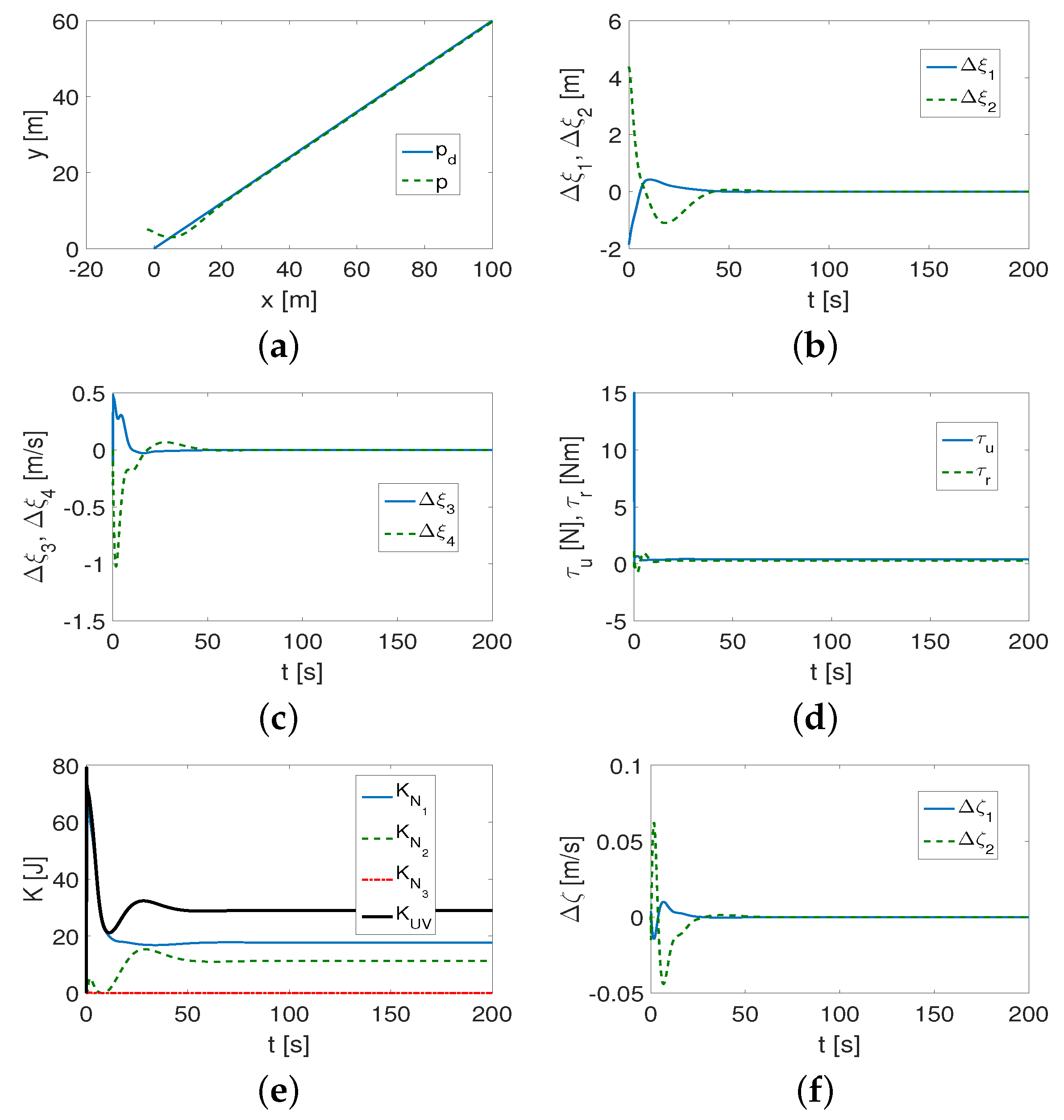
As can be seen in Figure 2a, the desired trajectory is correctly tracked. Observing Figure 2b,c, it may be noted that, after about 50 s, the position and velocity error states are close to zero. The applied force τ u and torque τ r given in Figure 2d are highest at the beginning of vehicle movement. However, the dominant value is τ u . Figure 2e shows that the largest part of the kinetic energy is consumed by a variable ζ 1 that refers to the lateral movement of the vehicle. The mean values of kinetic energy are: K m = 29.767 J (where K m 1 = 18.938 J, K m 2 = 10.825 J, K m 3 = 0.004 J). Moreover, from Figure 2f, it can be observed that the velocity disturbance values are larger for Δ ζ 2 (about 0.06 m/s), whereas for Δ ζ 2 , they are much smaller. Thus, the couplings are mainly concerned with lateral velocity.
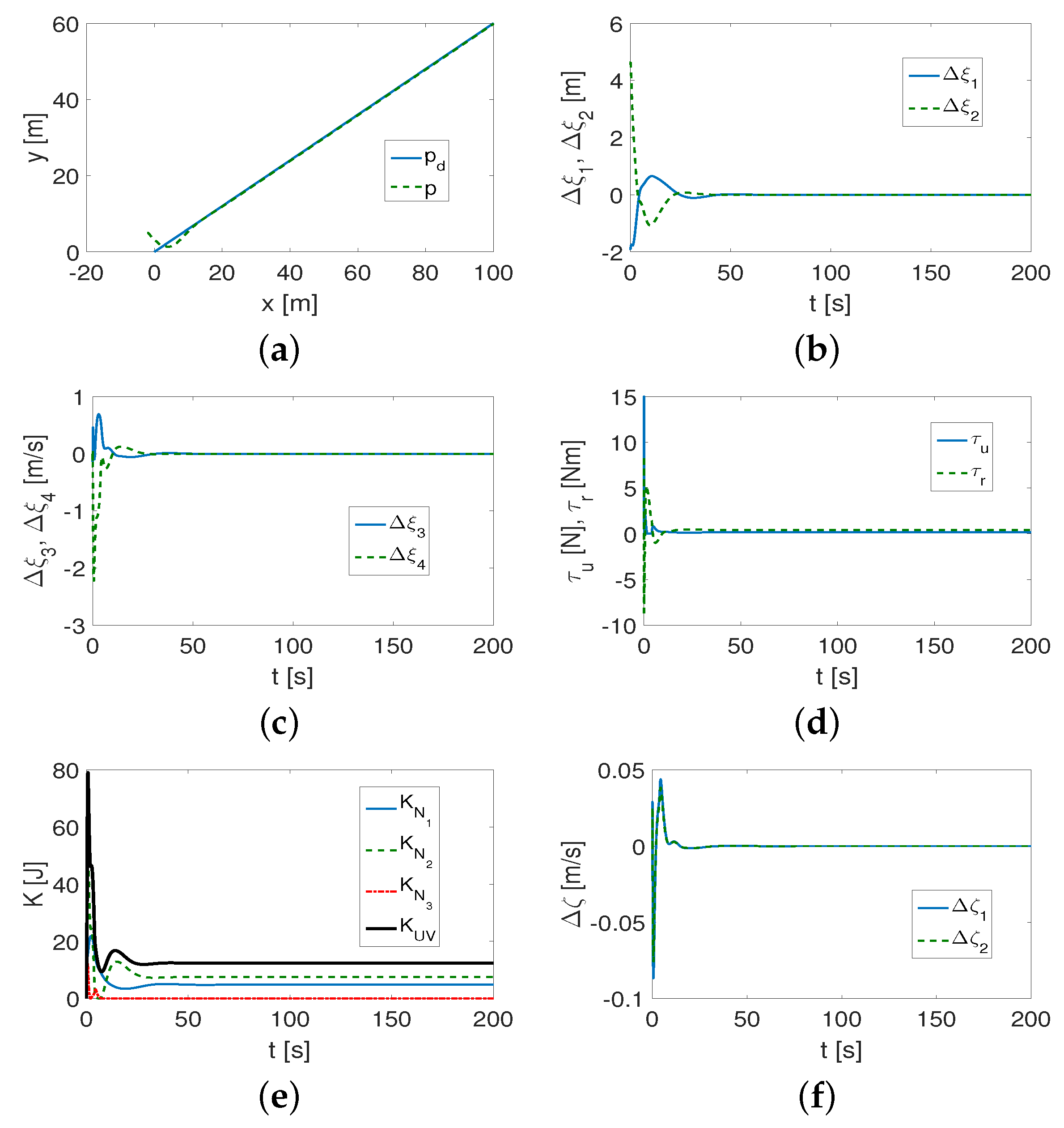
For the same linear trajectory and the XX AUV vehicle, the results of the test are shown in Figure 3. From Figure 3a, it is observed that the vehicle converges to the reference trajectory. The position and velocity error states tend to zero, as seen in Figure 3b,c after about 40 s. The applied force and torque history is presented in Figure 3d. However, in the beginning, both the force and moment contribute to the movement of the vehicle and reach large values. Figure 3e shows that the kinetic energy is mainly dissipated due to the lateral movement of the vehicle but the longitudinal movement is also significant. The mean values of kinetic energy are: K m = 13.195 J (and K m 1 = 5.165 J, K m 2 = 7.952 J, K m 3 = 0.078 J). From Figure 3f, it is noted that the dynamical couplings represented by the velocity errors Δ ζ 1 , Δ ζ 2 are comparable, which indicates that the velocity couplings are comparable in both directions (x and y). Their values are even higher than those of Kambara.
A sine-cosine trajectory described by p d = 0.5 t , 10 sin 0.02 t + 5 cos 0.01 t T , with the starting point p 0 = [ 2 5 ] T for Kambara and XX AUV, was selected for the second test. The same gain sets as previously, i.e., (42), (43), respectively, were assumed.
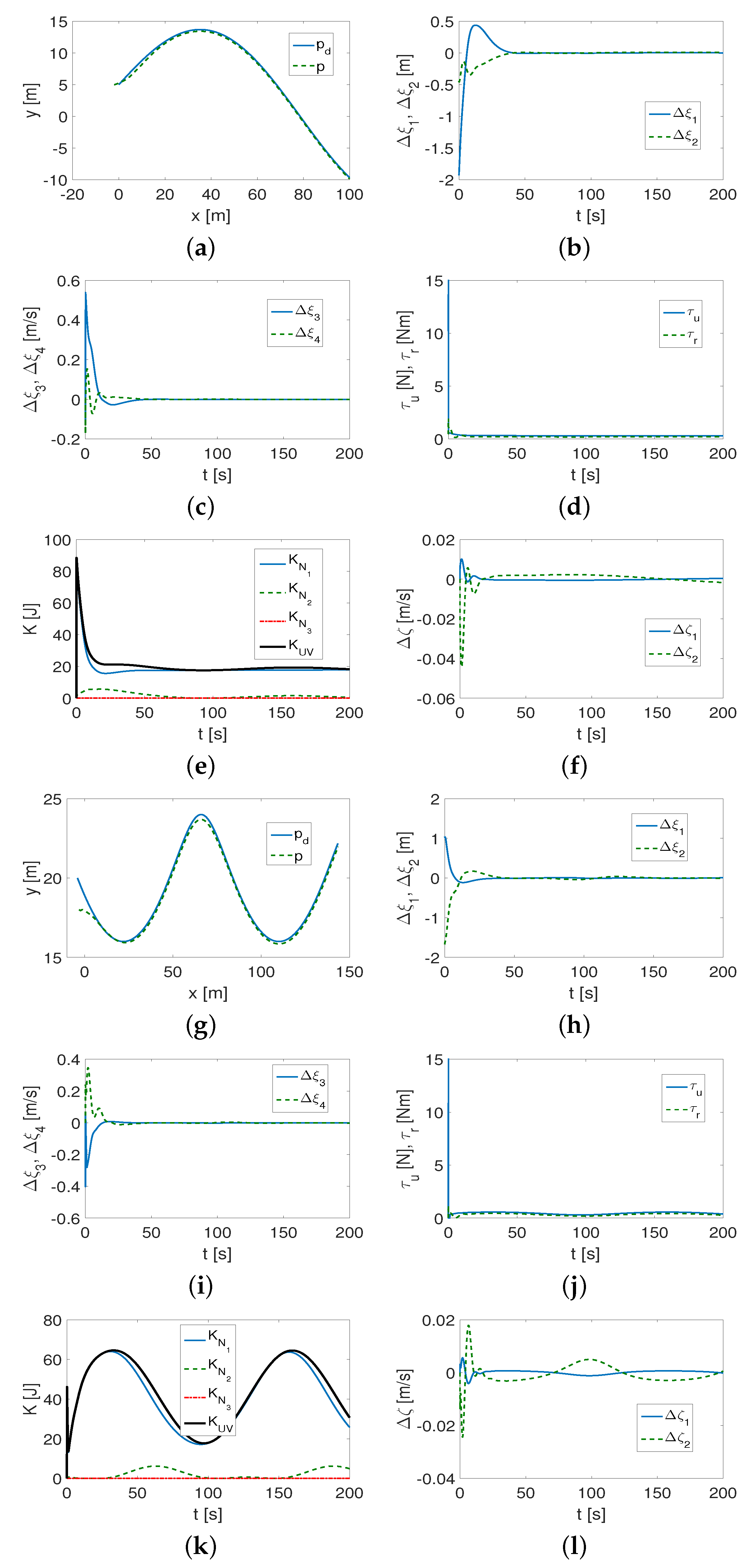
From Figure 4a, it is found that, for Kambara, the algorithm works correctly. The position and velocity error states are close to zero after about 40 s (Figure 4b,c). The applied force and torque values are similar to the linear trajectory, as depicted in Figure 4d. Figure 4e shows that the kinetic energy is reduced first by longitudinal motion of the vehicle. The mean kinetic energy values obtained are: K m = 20.693 J (and K m 1 = 18.902 J, K m 2 = 1.790 J, K m 3 = 0.001 J). However, the speed deformation, represented by variables Δ ζ 1 , Δ ζ 2 , is smaller than for the linear trajectory and varies during the motion, as shown in Figure 4f.
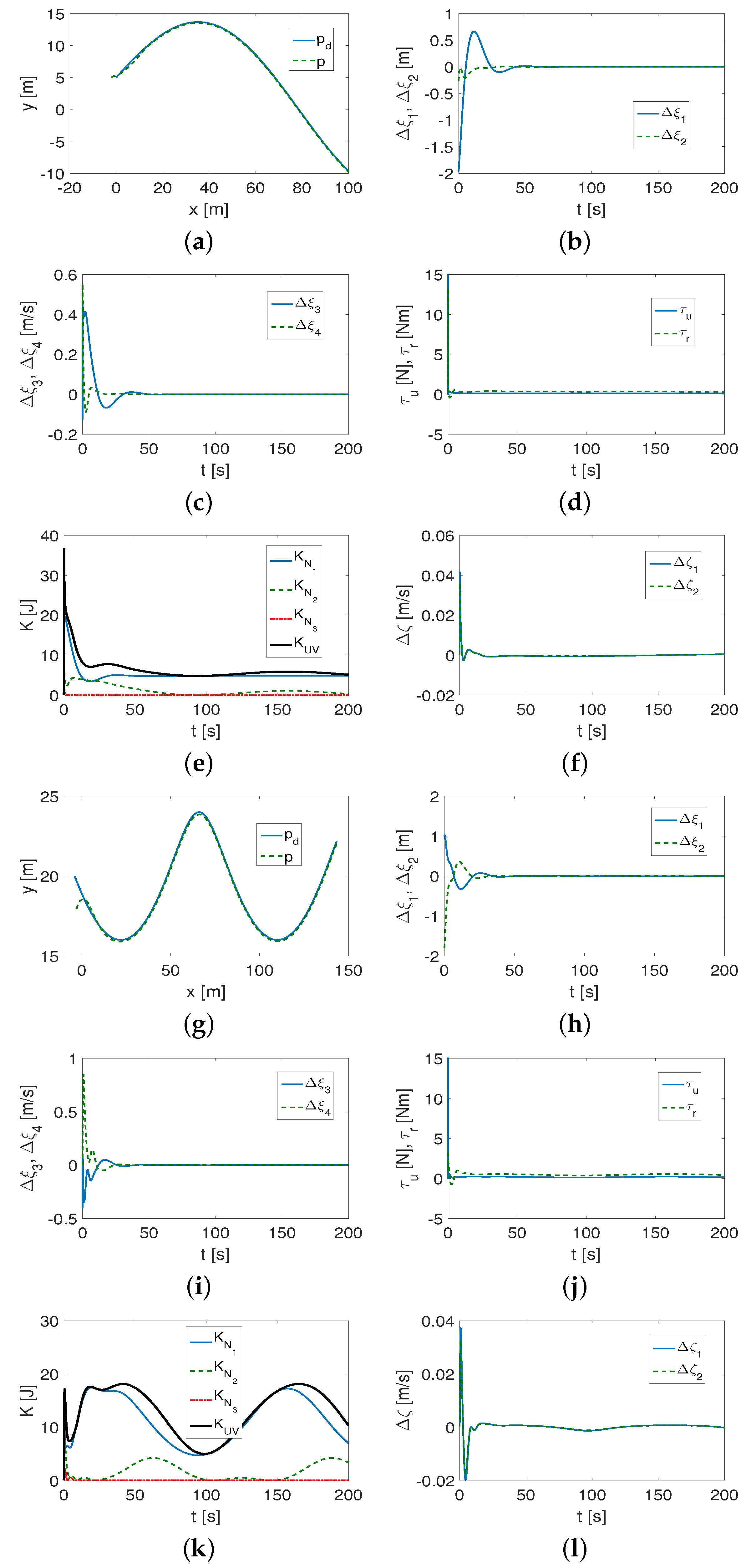
In Figure 5, the results for the XX AUV model are given. From Figure 5a, it can be noted that the control algorithm works correctly. This fact is confirmed in Figure 5b,c, where the position and velocity error states are shown. Although the applied force and torque are small (Figure 5d), they change as the vehicle moves along the trajectory. From the kinetic energy time history, depicted in Figure 5e, it can be seen that the longitudinal movement of the vehicle causes the greatest consumption of kinetic energy. In this case, the mean kinetic energy values are: K m = 6.365 J (and K m 1 = 5.133 J, K m 2 = 1.225 J, K m 3 = 0.006 J).
A slightly greater deformation of the velocity (errors Δ ζ 1 , Δ ζ 2 ) occurs than for the linear trajectory, as shown in Figure 5f. The couplings in both directions of horizontal motion are very close to each other.
A cycloid-like trajectory described by p d = 0.7 t 4 cos 0.05 t , 20 4 sin 0.05 t T , with the start point p 0 = [ 3 18 ] T for Kambara and XX AUV, was assumed.
The gains set was slightly changed in order to obtain better performance of the controller, namely:
K a m b a r a k v x = k v y = 12 , k p x = k p y = 4 , k I x = k I y = 0.4 ,
X X   A U V k v x = k v y = 5 , k p x = k p y = 1 , k I x = k I y = 0.3 .
The used test trajectory is different from the previous two because of its much smaller curvature. In Figure 4g–l, the results for Kambara are depicted. From Figure 4g, it is observed that the task is performed quickly and correctly. However, when tracking the curvature, the error values are larger. The position and velocity error states tend to zero after about 40 s, as shown in Figure 4h,i. The time history of the applied force and torque given in Figure 4j is similar to the history of the sine-cosine trajectory. Figure 4k shows that most of the kinetic energy is absorbed by the forward motion of the vehicle, similarly to the sine-cosine trajectory. However, the shape of the kinetic energy history is different because the change occurs as the shape of the trajectory tracked changes. The mean values of the kinetic energy are: K m = 44.763 J (and K m 1 = 42.524 J, K m 2 = 2.238 J, K m 3 = 0.001 J).
The maximum values of the velocity deformation ( Δ ζ 1 , Δ ζ 2 errors) caused by the couplings are smaller than for the previous two trajectories, but the deformation fluctuates with the evolution of the shape of the trajectory, as shown in Figure 4l.
The corresponding results obtained for the vehicle XX AUV are depicted in Figure 5g–l. From Figure 5g, it can be seen that the trajectory is tracked correctly. Similar conclusions can be drawn based on the graph presented in Figure 5h,i, where the positions and velocity error states are given. The applied forces and torque shown in Figure 5j have small values, with the exception of the first phase of the vehicle’s motion, and reflect changes in the trajectory shape. In Figure 5k, it can be found that most of the kinetic energy is reduced by longitudinal motion. Due to the shape of the change in this energy, the same effect is found for the Kambara vehicle for the same trajectory. The mean values of the kinetic energy are: K m = 13.144 J (and K m 1 = 11.512 J, K m 2 = 1.611 J, K m 3 = 0.021 J). The velocity deformations caused by the couplings at the beginning of the vehicle movement have large values, but, at all times, they are comparable for the longitudinal and lateral movements, as evidenced by the variables Δ ζ 1 , Δ ζ 2 shown in Figure 5l.
Analysis of results based on indexes. To estimate the qualitative results obtained in the QV driver test, an analysis was performed based on the selected indexes.
  • mean of the elements (mean), i.e., mean( Δ ξ 12 ), where Δ ξ 12 = | Δ ξ 1 | + | Δ ξ 2 | ; mean( Δ ξ 34 ), where Δ ξ 34 = | Δ ξ 3 | + | Δ ξ 4 | ; mean( Δ p x y ), where Δ p x y = | Δ p x | + | Δ p y | ;
  • the standard deviation of the elements (std), i.e., std( Δ ξ 12 ), std( Δ ξ 34 ), std( Δ p x y );
  • root mean square of the tracking error, i.e., R M S = 1 t f t 0 t 0 t f e ( t ) 2 d t ,
    with e ( t ) = Δ p x 2 + Δ p y 2 ( Δ p x , Δ p y —the position errors in the reference frame);
  • mean integrated absolute control, i.e., M I A C = 1 t f t 0 t 0 t f | A ( t ) | d t , where A = τ u , τ r .
The index values are summarized in Table 4.
The mean error values are mostly smaller for the XX AUV than for the Kambara. There are also smaller values of the thrust force of the vehicle τ u . These values are related to the mass of the vehicle. For the position and velocity state errors, this is not necessarily the case. It follows that these states are not crucial for the actual errors but indicate how well the algorithm is working. In contrast, the RMS and mean( Δ p x y ) show this explicitly. Another observation is that the control tracking accuracy depends on the realized trajectory. For both vehicles, better tracking accuracy was obtained for curvilinear trajectories than for linear trajectories. This may suggest that tracking the latter is more difficult for the QV-based algorithm.

4.1.2. Comparison with Classic Controller

Analogous tests, that is, for the same vehicles, trajectories and initial conditions, as well as the same operating conditions, were carried out using the control scheme of [38] (referred to here as the classic controller).
The parameters of the classical regulator, which guaranteed acceptable error convergence, were chosen as follows:
K a m b a r a k v x = k v y = 25 , k p x = k p y = 5 , k I x = k I y = 0.5 ,
X X   A U V k v x = k v y = 30 , k p x = k p y = 5 , k I x = k I y = 0.5 .
Attempting to change these values did not yield better results than those presented in this section of the article.
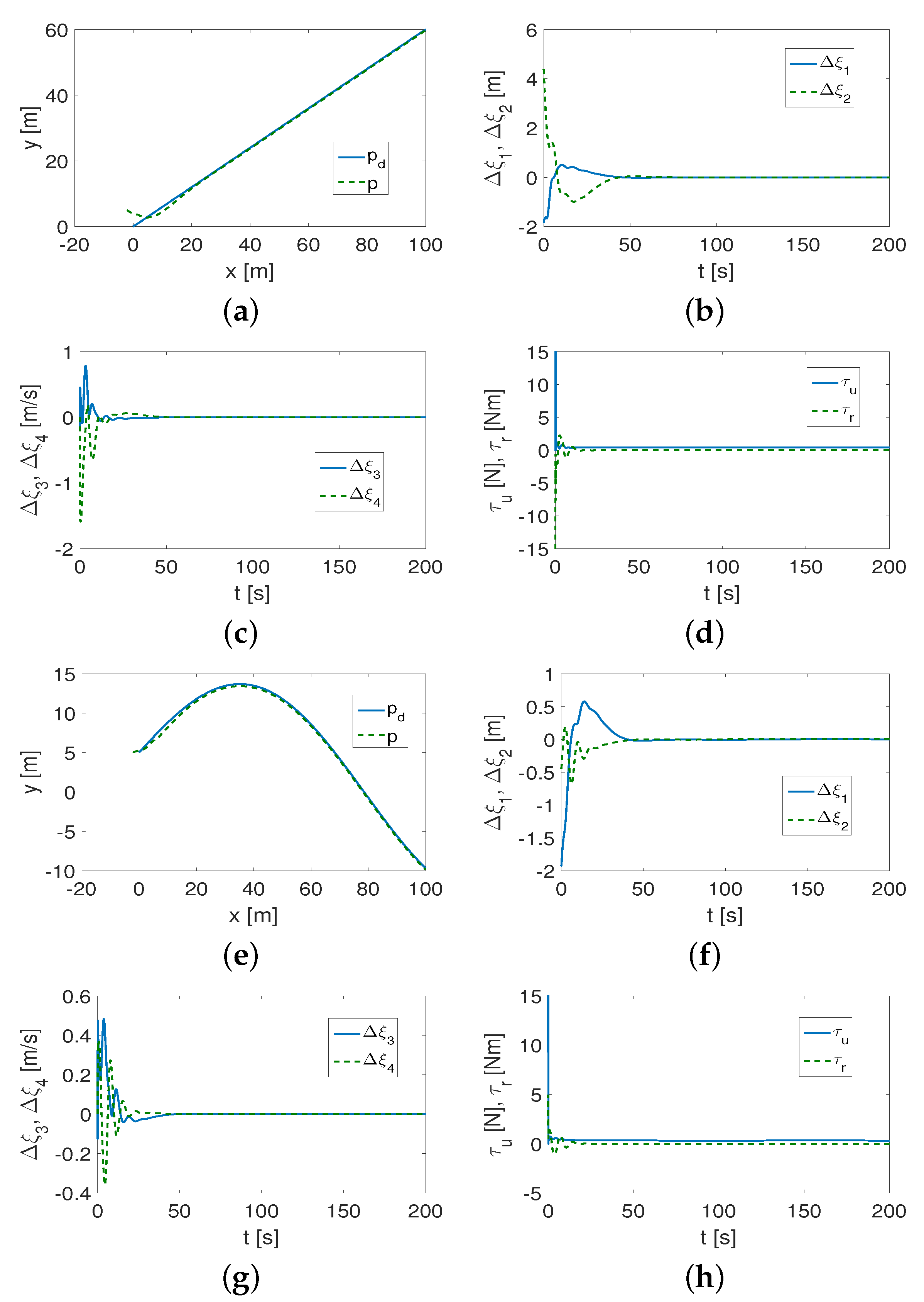
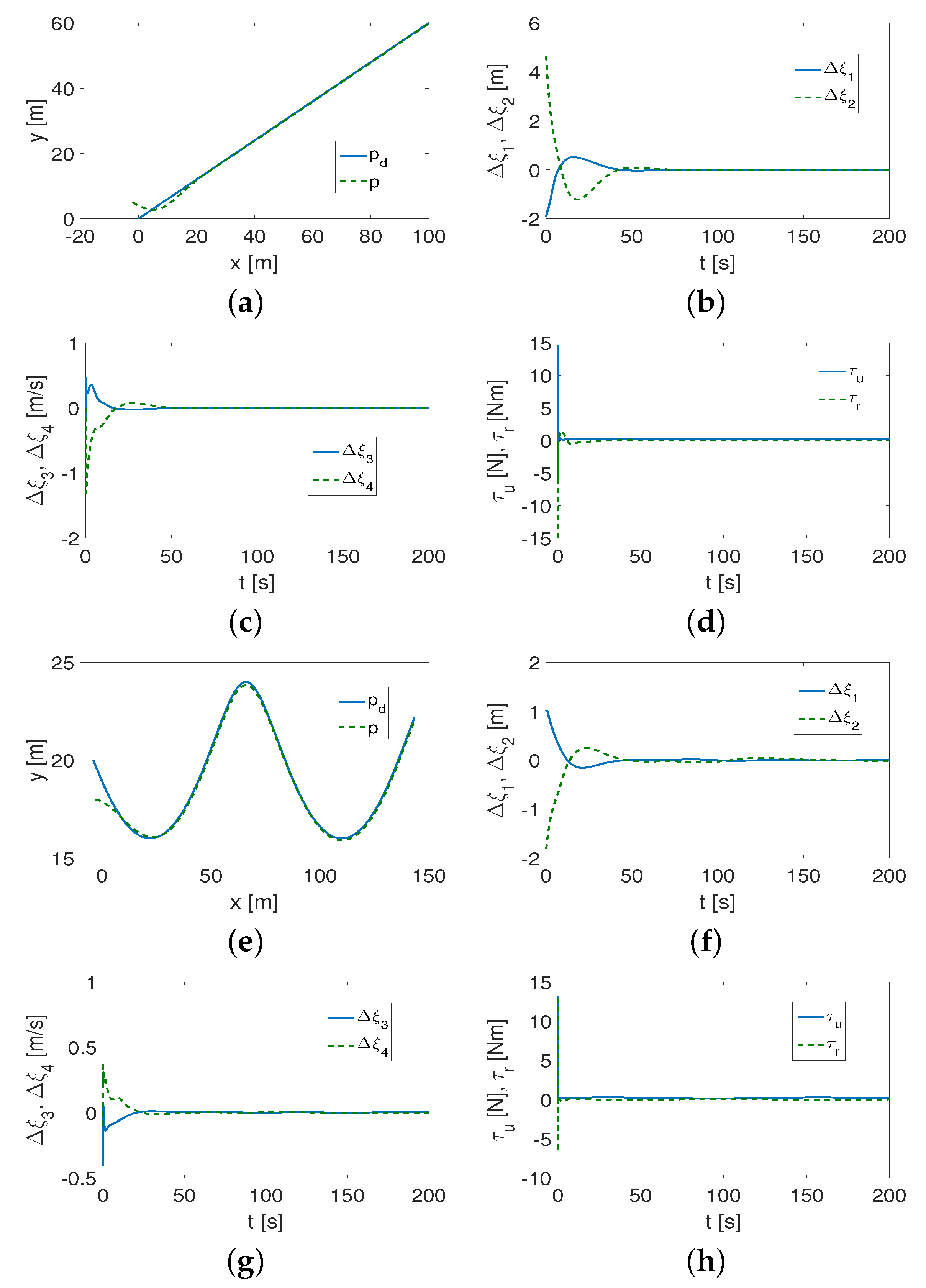
Linear trajectory. The results obtained for Kambara are given in Figure 6. They are similar to those presented in Figure 2. As can be seen from Figure 6a–d, the controller is working properly. However, the velocity error states, as shown in Figure 6c, have larger values at the beginning and are more disturbed.
Acceptable results were also obtained for the XX AUV, as shown in Figure 7a–d. The velocity error states (Figure 7c) do not change as quickly as for Kambara.
Sine-cosine trajectory. For this trajectory, the simulation results are presented for the Kambara vehicle only in Figure 6a–d. The controller works properly, but, again, the errors Δ ξ 3 , Δ ξ 4 (Figure 6g) significantly change their values when the vehicle starts moving, which is not noticeable when an algorithm containing QV is used (Figure 4c).
Cycloid-like trajectory. Figure 7e–h present the results for the XX AUV only. As can be easily seen, the algorithm works correctly and the desired trajectory is tracked. The effects are similar to those shown in Figure 5g–j. However, the changes in the error states here are not as fast as for the QV controller (cf. Figure 5h,i and Figure 7f,g).
Analysis of results based on indexes. The performance of the classic controller is given in Table 5. Slightly better results were obtained for the XX AUV than for the Kambara for the actual errors, although this was not always consistent with the error values of the position and velocity states. In addition, there is a greater reduction in the tracking accuracy for the linear trajectories than for the curvilinear trajectories. The mean thrust values τ u are much larger than the mean torque values τ r , leading to the conclusion that the linear motion of the vehicle dominates.

4.1.3. Comparison with Algorithm Based on Velocity Transformations

To compare the results obtained with the proposed control algorithm, simulation tests were performed for analogous operating conditions using the control scheme developed in [48]. The algorithm chosen is a combination of backstepping, control of the integral sliding mode, and velocity transformation. Thus, its working idea is different from that of the proposed controller. In addition, it is also suitable for a fully asymmetric model like the modified controller considered in this paper. This controller is denoted here as VT (based on velocity transformation). Due to a different control idea, limitations on force and torque were taken in | τ u | 120 N and | τ r | 37 Nm, respectively. These values can be obtained considering the engines installed in the Kambara vehicle. Constant disturbances were adopted to keep the direction and nature of the operation consistent with previously assumed disturbances, that is, 5 N along the x-axis and 10 Nm along the y-axis. Tests were performed for a Kambara vehicle that realized a linear and sine-cosine trajectory.
Linear trajectory. The set of control parameters in the algorithm proposed in [48]
K a m b a r a k 1 = k 2 = 0.20 , k 3 = 10 ; k 4 = 1 , k 5 = 5 ,
was selected in order to guarantee fast response and acceptable tracking errors. The mean values of the calculated kinetic energy were: K m = 61.319 J (and K m 1 = 58.586 J, K m 2 = 2.510 J, K m 3 = 0.223 J). The energy values are higher than those with the algorithm proposed in this paper. Thus, the controller described in [48] consumes energy.
The results of the simulation are shown in Figure 8.
From Figure 8a,b, it can be seen that the tracking of the desired trajectory is implemented correctly; however, there is deformation when the vehicle begins to move. During this time, there is a large increase in the kinetic energy (Figure 8c) and also in the force and torque (Figure 8d).
Sine-cosine trajectory. For this desired trajectory, the set of parameters was slightly changed to improve the control performance. It was as follows:
K a m b a r a k 1 = k 2 = 0.30 , k 3 = 10 ; k 4 = 1 , k 5 = 5 .
The algorithm worked correctly, and for this trajectory only index values were given. The performance indexes for the VT control algorithm are presented in Table 6.
A comparison of the proposed QV controller with the VT controller can be made based on the results shown in Table 4 and Table 6. As can be seen from the data, in the tables, the VT controller had larger mean values mean( Δ p x y ) and standard deviation (except for the mean error for the SC trajectory) for the tracking error. Even if corrected, the results for the VT controller (assuming a different set of parameters) would be comparable, but there could be undesirable oscillations. Therefore, it can be concluded that, for the assumed operating conditions, the proposed control algorithm is more efficient than the VT algorithm. The advantage of the QV controller is also evidenced by the fact that the values of the input signals are much smaller than those of the VT controller.

4.2. Discussion of Results

Models of two vehicles with different dynamics and three types of desired trajectories were investigated. The test results of the QV-based control scheme can be summarized as follows.
(1)
It was found that the performance of the control algorithm is affected by both vehicle dynamics and the selection of the desired trajectory.
(2)
The curvature of the trajectory (smaller radius of curvature) causes more interference at the beginning of the vehicle movement, and this, in turn, forces the controller to increase the control signals. The result can be a reduction in the trajectory-tracking accuracy unless the value of the coefficient l is reduced.
(3)
Not only are the gains of the controllers k v x , k v y , k p x , k p y , k I x , k I y important for tracking the desired trajectory, but the value of the l parameter is also essential. If l has a large value ( l > 1 ), then, in the case of trajectories with small curvature (which should be determined after performing a simulation to check the accuracy of trajectory tracking), tracking occurs after a short time, but is inaccurate during movement (tracking errors in the x-y plane increase). The value of the coefficient s f depends on the weight of the vehicle, and, more specifically, on its dynamic parameters.
(4)
It turned out that the algorithm is somehow robust to changes in the appropriately selected set of control gains. This means that the same set of gains can be applied to different trajectories and only slightly modified to track trajectories with sufficiently small curvature.
(5)
Investigating the distribution of kinetic energy consumption across variables representing quasi-velocities and velocity deformations caused by dynamic couplings in the vehicle provides additional insight into its dynamics. The time history of this energy indicates for which QV the reduction is greatest (in which direction of motion), and how the changes occur for different shapes of the desired trajectory.
(6)
The variables Δ ζ i also reflect the shape of the trajectory because they can change as the vehicle moves.
Simulation tests performed under other operating conditions and also for another vehicle indicate the suitability of the proposed algorithm, both for control purposes and for study of the dynamics of marine vehicles.
Analysis of the results obtained from the QV-based controller and the classical one.
(1)
Comparative observations of the figures show that both the QV and CL controllers work correctly, although, in some cases, the error convergence time may be shorter for the QV controller than for the CL controller. This may be due to the fact that coupling in the lateral direction is included in the control equation.
(2)
The proposed performance indexes provide more information. It can be seen that, for both algorithms, their effectiveness depends on the parameters of the vehicle model and the trajectory being tracked.
(3)
Based on the values of the indexes in Table 4, Table 5 and Table 6, it can be observed that:
  • After applying the CL algorithm, the smaller index values are not determined by the dynamic parameters of the vehicle because some of the smaller index values apply to the Kambara vehicle and some to XX AUV. Therefore, it is difficult to identify the relationship between the performance and the vehicle dynamics. Having applied the algorithm using QV, it is clear that smaller index values were obtained more often for the XX AUV vehicle than for the Kambara. From this it can be concluded that the effectiveness of the proposed controller depends, to some extent, on the dynamic parameters of the vehicle, which is not seen for the CL one.
  • The calculated index values show that both algorithms track linear trajectories with less accuracy than curvilinear trajectories.
  • The base indexes (that is, without force and torque) are mostly lower for each vehicle after using the QV controller when we compare them with the indexes obtained from the CL algorithm. The advantage is more evident for the actual errors (mean( Δ p x y ) and RMS( | | e | | )). It is worth noting that the errors in the position and velocity states indicate whether the algorithm correctly performs the tracking task, but the actual errors are larger, which is, however, in line with the assumptions of both the original (CL controller) and the modified (QV controller) methods. Since the QV-based control scheme takes into account both the longitudinal and lateral asymmetry of the vehicle, while CL only takes into account the longitudinal asymmetry, it would seem that it is the CL algorithm that should be more effective in performing the task of trajectory tracking. The fact that this is very often not the case can be explained by modifications to the controller that use the dynamic parameters of the vehicle.
  • Both controllers, i.e., QV and CL, primarily use the driving force, but smaller values are provided by the QV algorithm. In contrast, the average torque is much lower (close to zero) for the CL controller. The reason for this is the taking of vehicle dynamics into account, as it is necessary to provide larger values of this torque.
  • Compared to the other control scheme tested, here denoted VT, it turned out that, for the assumed operating conditions and desired trajectories, the considered QV algorithm gave slightly better performance with respect to the tracking errors with significantly lower values of the control signals.
(4)
It is worth noting that a properly selected set of control coefficients allows some flexibility because it can be applied to different trajectories (at most with a slight change in value).
(5)
Using the QV controller, more information is obtained on the dynamics of the vehicle than the CL controller. This is one of the essential differences between the two control schemes.
Limitations and disadvantages of the algorithm using QV can be summarized in several points.
  • According to the idea presented in [38] and used to design the QV-based controller, only the convergence of the position and velocity state errors to zero is guaranteed. This means that the real position errors (represented by the values of RMS( | | e | | ) and mean( Δ p x y )) can tend to certain constant values. This is what would explain their larger values than the values of the state errors.
  • In addition to the controller parameters k v x , k v y , k p x , k p y , k I x , k I y and the l parameter, the quality of the results is also affected by the value of the additional factor s f , so the total number of parameters is one more than for a classic controller. However, the advantage of s f is that it is adopted according to the dynamic parameters of the vehicle and can be tuned even if the algorithm does not work properly with another set of gains.
  • It takes quite a long time to reach the convergence values of the position and velocity states, even with the correct choice of controller gains. This time can be reduced by decreasing the values of k v x , k v y , but then oscillations and rapid changes in the error values will occur. To avoid this phenomenon, the values of k v x , k v y can be increased, but this will increase the convergence time of the state errors to zero. Therefore, a compromise between all gain values is important.

5. Conclusions

In this work, an algorithm in terms of quasi-velocities is considered for fully asymmetric vehicle models. It is based on the idea of trajectory-tracking control proposed by Paliotta et al. [38]. The main difference between the two algorithms is that the dynamic parameters of the marine vehicle are taken into account in the proposed controller differently than for the original algorithm. In contrast to the description provided in the source work, the velocity transformation method is applied here to obtain the first-order differential equations. Furthermore, the extension of the method consists in the fact that, in this work, dynamic couplings are present in the x- and y-directions, whereas, in the original work, only couplings in the x-direction were assumed. As a result of changing the description of the vehicle dynamics, it is possible to extend the function of the control algorithm to the estimation of couplings in the vehicle model. The aim of the work was to show the possibilities offered by the modified algorithm in the case of the presence of couplings in both directions of vehicle movement, i.e., one that allowed tracking the desired trajectory when the vehicle is asymmetric in two planes. Simulation tests were carried out for two vehicle models with different dynamics and three desired trajectories to show the relationship between the vehicle model and the realized trajectory. Based on numerical simulations, it has been shown that it is possible not only to track a desired trajectory, but also to gain some insight into vehicle dynamics. Comparing the performance of the algorithms, the proposed QV, the classic CL [38] and another one that was taken for the study [48], it turned out that the former was more efficient than the others given the assumptions made and the operational conditions. Therefore, the proposed modified algorithm can be used not only to control underwater vehicles, but also to test the model of their dynamics. Future research should explore other control methods suitable for vehicles with full asymmetry because such algorithms, in reduced form, are also suitable for partially symmetric or fully symmetric vehicles.

Funding

The work was supported by Poznan University of Technology Grant No. 0211/SBAD/0122.

Institutional Review Board Statement

Not applicable.

Informed Consent Statement

Not applicable.

Data Availability Statement

Not applicable.

Conflicts of Interest

The author declares no conflict of interest.

Appendix A

The dynamic equation of a vehicle, instead of (2), may be expressed in the form:
M ν ˙ r + C ( ν r ) ν r + D ν r = B f ,
where:
B = b 11 0 0 b 22 Υ 13 b 11 b 32 ,
is the actuator configuration matrix and f = [ T u , T r ] T , where T u is the thruster force and T r is the rudder angle. The vector B f can also represent the force and moment resulting from the configuration of the motors. Taking into account the velocity transformation and its time derivative:
ν r = Υ 1 κ r , κ r = Υ 1 1 ν r , κ r = [ u r Υ 13 r , v r , r ] T , κ ˙ r = Υ 1 1 ν ˙ r .
Instead of (4), the kinematic Equations ( u r = κ 1 r + Υ 13 r ) have the form:
x ˙ = ( κ 1 r + Υ 13 r ) cos ψ v r sin ψ + V x ,
y ˙ = ( κ 1 r + Υ 13 r ) sin ψ + v r cos ψ + V y ,
ψ ˙ = r .
Inserting Υ 1 from (30) into (A1), and multiplying by Υ 1 T , as a result, the equation of motion dynamics is as follows:
M ν ˙ r + C ( ν r ) ν r + D ν r = B f ,
Υ 1 T M Υ 1 κ ˙ r + Υ 1 T C ( ν r ) ν r + Υ 1 T D ν r = Υ 1 T B f ,
P κ ˙ r + Υ 1 T C ( ν r ) ν r + Υ 1 T D ν r = Υ 1 T B f .
Denoting B * = Υ 1 T B , it can be written:
κ ˙ r = P 1 H + P 1 B * f ,
where H = Υ 1 T C ( ν r ) ν r + Υ 1 T D ν r and:
P 1 = p ¯ 11 0 0 0 p ¯ 22 p ¯ 23 0 p ¯ 23 p ¯ 33 , P 1 B * f = p ¯ 11 b 11 T u ( p ¯ 22 b 22 + p ¯ 23 b 32 ) T r ( p ¯ 23 b 22 + p ¯ 33 b 32 ) T r .
The symbols used have the following meanings: p ¯ 11 = m 11 1 , p ¯ 22 = p 33 / Δ , p ¯ 23 = m 23 / Δ , p ¯ 33 = m 22 / Δ , Δ = m 22 p 33 m 23 2 . In [38], the pivot point is selected to ensure that M 1 B f = [ τ u , 0 , τ r ] T is not Υ 13 b 11 without the element Υ 13 b 11 in the matrix B (A2). Here, due to lateral asymmetry, it must be taken into account. Therefore, the position of the pivot point is calculated from p ¯ 22 b 22 + p ¯ 23 b 32 = 0 to ensure that the element of the second row is null. Thus, the above condition can be written as ( m 33 ( m 13 2 / m 11 ) ) b 22 m 23 b 32 = 0 .
Consequently, the matrix-vector equation can be written in the form of:
κ ˙ 1 r = p ¯ 11 H 1 + τ u ,
v ˙ r = p ¯ 22 H 2 p ¯ 23 H 3 ,
r ˙ = p ¯ 23 H 2 p ¯ 33 H 3 + τ r ,
where:
H 1 = c 13 r + d 11 κ 1 r + ( d 13 + d 11 Υ 13 ) r ,
H 2 = ( m 11 κ 1 r 2 m 13 r ) r + d 22 v r + d 23 r ,
H 3 = c 13 κ 1 r ( m 11 κ 1 r 2 m 13 r ) v r + ( d 31 + Υ 13 d 11 ) κ 1 r + d 32 v r + d 33 + Υ 13 ( d 13 + d 31 + Υ 13 d 11 ) r ,
denoting κ 1 r = u r Υ 13 r . Introducing the symbols: d 311 = d 31 + Υ 13 d 11 , d 312 = d 33 + Υ 13 ( d 13 + d 31 + Υ 13 d 11 ) , one has:
v ˙ r = ( p ¯ 22 m 11 + p ¯ 23 m 23 ) κ 1 r ( p ¯ 22 d 23 + p ¯ 23 d 312 ) r + ( p ¯ 23 m 22 p ¯ 23 m 11 ) κ 1 r ( p ¯ 22 d 22 + p ¯ 23 d 32 ) v r + 2 p ¯ 22 m 13 r 2 2 p ¯ 23 m 13 r v r p ¯ 23 d 311 κ 1 r .
The residual components W = 2 p ¯ 22 m 13 r 2 2 p ¯ 23 m 13 r v r p ¯ 23 d 311 κ 1 r can be analyzed for inclusion in the other two components. It is assumed that δ 1 m a x = | 2 p ¯ 22 m 13 r m a x | ( r m a x means the maximum value of r), δ 2 m a x = | 2 p ¯ 23 m 13 r m a x | ( r m a x means the maximum value of r), and δ 3 m a x = | p ¯ 23 d 311 κ 1 r m a x | ( κ 1 r m a x means the maximum value of κ 1 r ). For the component W to be non-negative, the condition must be met:
δ 1 m a x r + δ 2 m a x v r δ 3 m a x ,
and then it is assumed W = δ 1 m a x r + δ 2 m a x v r . In other cases, i.e., if:
δ 1 m a x r + δ 2 m a x v r < δ 3 m a x ,
it should be assumed W = a 1 δ 3 m a x r + a 1 δ 3 m a x v r , where a 1 is a constant guaranteeing that W δ 3 m a x . Taking into account the results obtained and denoting that X 1 = p ¯ 22 m 11 + p ¯ 23 m 23 , Y 1 = p ¯ 23 m 22 p ¯ 23 m 11 as well as X 2 = δ 1 m a x p ¯ 22 d 23 p ¯ 23 d 312 (or X 2 = a 1 δ 3 m a x p ¯ 22 d 23 p ¯ 23 d 312 ), Y 2 = p ¯ 22 d 22 + p ¯ 23 d 32 δ 2 m a x (or Y 2 = p ¯ 22 d 22 + p ¯ 23 d 32 a 1 δ 3 m a x ) Equation (A18) can be rewritten as:
v ˙ r = X ( κ 1 r ) r + Y ( κ 1 r ) v r ,
where: X ( κ 1 r ) = X 1 κ 1 r + X 2 and Y ( κ 1 r ) = Y 1 κ 1 r Y 2 .
Equations (A12)–(A17) are analogous to the dynamic equations in [38], but include the quasi-velocity κ 1 r resulting from the partial decomposition of the inertia matrix M. A similar analog can be found in Equation (A21).

References

  1. Do, K.D.; Pan, J. Control of Ships and Underwater Vehicles; Springer: London, UK, 2009. [Google Scholar]
  2. Fossen, T.I. Guidance and Control of Ocean Vehicles; John Wiley and Sons: Chichester, UK, 1994. [Google Scholar]
  3. Aguiar, A.P.; Hespanha, J.P. Trajectory-Tracking and Path-Following of Underactuated Autonomous Vehicles with Parametric Modeling Uncertainty. IEEE Trans. Autom. Control 2007, 528, 1362–1379. [Google Scholar] [CrossRef] [Green Version]
  4. Zhang, L.J.; Qi, X.; Pang, Y.J. Adaptive output feedback control based on DRFNN for AUV. Ocean Eng. 2009, 36, 716–722. [Google Scholar] [CrossRef]
  5. Bechlioulis, C.P.; Karras, G.C.; Heshmati-Alamdari, S.; Kyriakopoulos, K.J. Trajectory Tracking with Prescribed Performance for Underactuated Underwater Vehicles Under Model Uncertainties and External Disturbances. IEEE Trans. Control Syst. Technol. 2017, 25, 429–440. [Google Scholar] [CrossRef]
  6. Fetzer, K.L.; Nersesov, S.; Ashrafiuon, H. Nonlinear control of three-dimensional underactuated vehicles. Int. J. Robust Nonlinear Control 2020, 30, 1607–1621. [Google Scholar] [CrossRef]
  7. Fang, K.; Fang, H.; Zhang, J.; Yao, J.; Li, J. Neural adaptive output feedback tracking control of underactuated AUVs. Ocean Eng. 2021, 234, 109211. [Google Scholar] [CrossRef]
  8. Huang, B.; Zhou, B.; Zhang, S.; Zhu, C. Adaptive prescribed performance tracking control for underactuated autonomous underwater vehicles with input quantization. Ocean Eng. 2021, 221, 108549. [Google Scholar] [CrossRef]
  9. Liu, J.; Du, J. Composite learning tracking control for underactuated autonomous underwater vehicle with unknown dynamics and disturbances in three-dimension space. Appl. Ocean Res. 2021, 112, 102686. [Google Scholar] [CrossRef]
  10. Behal, A.; Dawson, D.M.; Dixon, W.E.; Fang, Y. Tracking and Regulation Control of an Underactuated Surface Vessel with Nonintegrable Dynamics. IEEE Trans. Autom. Control 2002, 47, 495–500. [Google Scholar] [CrossRef] [Green Version]
  11. Lefeber, E.; Pettersen, K.Y.; Nijmeijer, H. Tracking Control of an Underactuated Ship. IEEE Trans. Control Syst. Technol. 2003, 11, 52–61. [Google Scholar] [CrossRef] [Green Version]
  12. Ashrafiuon, H.; Muske, K.R.; McNinch, L.C.; Soltan, R.A. Sliding-Mode Tracking Control of Surface Vessels. IEEE Trans. Ind. Electron. 2008, 55, 4004–4012. [Google Scholar] [CrossRef]
  13. Zhang, L.; Huang, B.; Liao, Y.; Wang, B. Finite-Time Trajectory Tracking Control for Uncertain Underactuated Marine Surface Vessels. IEEE Access 2019, 7, 102321–102330. [Google Scholar] [CrossRef]
  14. Li, J.; Du, J.; Sun, Y.; Lewis, F.L. Robust adaptive trajectory tracking control of underactuated autonomous underwater vehicles with prescribed performance. Int. J. Robust Nonlinear Control 2019, 29, 4629–4643. [Google Scholar] [CrossRef]
  15. Zhang, J.X.; Chai, T. Singularity-Free Continuous Adaptive Control of Uncertain Underactuated Surface Vessels With Prescribed Performance. IEEE Trans. Syst. Man Cybern. Syst. 2022, 52, 5646–5655. [Google Scholar] [CrossRef]
  16. Pan, C.Z.; Lai, X.Z.; Wang, S.X.; Wu, M. An efficient neural network approach to tracking control of an autonomous surface vehicle with unknown dynamics. Expert Syst. Appl. 2013, 40, 1629–1635. [Google Scholar] [CrossRef]
  17. Duan, K.; Fong, S.; Chen, P. Fuzzy observer-based tracking control of an underactuated underwater vehicle with linear velocity estimation. IET Control Theory Appl. 2020, 14, 584–593. [Google Scholar] [CrossRef]
  18. Elmokadem, T.; Zribi, M.; Youcef-Toumi, K. Terminal sliding mode control for the trajectory tracking of underactuated Autonomous Underwater Vehicles. Ocean Eng. 2017, 129, 613–625. [Google Scholar] [CrossRef]
  19. Do, K.D.; Jiang, Z.P.; Pan, J.; Nijmeijer, H. A global output-feedback controller for stabilization and tracking of underactuated ODIN: A spherical underwater vehicle. Automatica 2004, 40, 117–124. [Google Scholar] [CrossRef]
  20. Serrano, M.E.; Scaglia, G.J.E.; Godoy, S.A.; Mut, V.; Ortiz, O.A. Trajectory Tracking of Underactuated Surface Vessels: A Linear Algebra Approach. IEEE Trans. Control Syst. Technol. 2014, 22, 1103–1111. [Google Scholar] [CrossRef]
  21. Do, K.D. Robust adaptive tracking control of underactuated ODINs under stochastic sea loads. Robot. Auton. Syst. 2015, 72, 152–163. [Google Scholar] [CrossRef]
  22. Sun, Z.; Zhang, G.; Qiao, L.; Zhang, W. Robust adaptive trajectory tracking control of underactuated surface vessel in fields of marine practice. J. Mar. Sci. Technol. 2018, 23, 950–957. [Google Scholar] [CrossRef]
  23. Xu, J.; Wang, M.; Qiao, L. Dynamical sliding mode control for the trajectory tracking of underactuated unmanned underwater vehicles. Ocean Eng. 2015, 105, 54–63. [Google Scholar] [CrossRef]
  24. Mu, D.; Wang, G.; Fan, Y. Trajectory tracking control for underactuated unmanned surface vehicle subject to uncertain dynamics and input saturation. Neural Comput. Appl. 2021, 33, 12777–12789. [Google Scholar] [CrossRef]
  25. Zhang, L.; Zheng, Y.; Huang, B.; Su, Y. Finite-time trajectory tracking control for under-actuated unmanned surface vessels with saturation constraint. Ocean Eng. 2022, 249, 110745. [Google Scholar] [CrossRef]
  26. Zhang, C.; Wang, C.; Wei, Y.; Wang, J. Neural-Based Command Filtered Backstepping Control for Trajectory Tracking of Underactuated Autonomous Surface Vehicles. IEEE Access 2020, 8, 42482–42490. [Google Scholar] [CrossRef]
  27. Zhou, J.; Zhao, X.; Chen, T.; Yan, Z.; Yang, Z. Trajectory Tracking Control of an Underactuated AUV Based on Backstepping Sliding Mode with State Prediction. IEEE Access 2019, 7, 181983–181993. [Google Scholar] [CrossRef]
  28. Zhang, C.; Wang, C.; Wang, J.; Li, C. Neuro-adaptive trajectory tracking control of underactuated autonomous surface vehicles with high-gain observer. Appl. Ocean Res. 2020, 97, 102051. [Google Scholar] [CrossRef]
  29. Deng, Y.; Zhang, Z.; Gong, M.; Ni, T. Event-Triggered Asymptotic Tracking Control of Underactuated Ships with Prescribed Performance. IEEE Trans. Intell. Transp. Syst. 2023, 24, 645–656. [Google Scholar] [CrossRef]
  30. Sun, X.; Wang, G.; Fan, Y. Trajectory Tracking Control for Vector Propulsion Unmanned Surface Vehicle with Incomplete Underactuated Inputs. IEEE J. Ocean Eng. 2023, 48, 80–92. [Google Scholar] [CrossRef]
  31. Liu, W.; Ye, H.; Yang, X. Super-Twisting Sliding Mode Control for the Trajectory Tracking of Underactuated USVs with Disturbances. J. Mar. Sci. Eng. 2023, 11, 636. [Google Scholar] [CrossRef]
  32. Mu, D.; Li, L.; Wang, G.; Fan, Y.; Zhao, Y; Sun, X. State constrained control strategy for unmanned surface vehicle trajectory tracking based on improved barrier Lyapunov function. Ocean Eng. 2023, 277, 114276. [Google Scholar] [CrossRef]
  33. Pan, B.; Chen, C.; Zhu, G.; Su, Y. Event-Triggered Composite Learning Finite-Time Trajectory Tracking Control for Underactuated MSVs Subject to Uncertainties. IEEE Access 2022, 10, 14440–14449. [Google Scholar] [CrossRef]
  34. Dong, Z.; Wan, L.; Liu, T.; Zeng, J. Horizontal-plane Trajectory-tracking Control of an Underactuated Unmanned Marine Vehicle in the Presence of Ocean Currents. Int. J. Adv. Robot. Syst. 2016, 13, 83. [Google Scholar] [CrossRef] [Green Version]
  35. Wang, N.; Xie, G.; Pan, X.; Su, S.F. Full-State Regulation Control of Asymmetric Underactuated Surface Vehicles. IEEE Trans. Ind. Electron. 2019, 66, 8741–8750. [Google Scholar] [CrossRef]
  36. Do, K.D. Practical control of underactuated ships. Ocean Eng. 2010, 37, 1111–1119. [Google Scholar] [CrossRef]
  37. Wang, C.; Xie, S.; Chen, H.; Peng, Y.; Zhang, D. A decoupling controller by hierarchical backstepping method for straight-line tracking of unmanned surface vehicle. Syst. Sci. Control Eng. 2019, 7, 379–388. [Google Scholar] [CrossRef]
  38. Paliotta, C.; Lefeber, E.; Pettersen, K.Y.; Pinto, J.; Costa, M.; Borges de Sousa, J.Td.F. Trajectory Tracking and Path Following for Underactuated Marine Vehicles. IEEE Trans. Control Syst. Technol. 2019, 27, 1423–1437. [Google Scholar] [CrossRef] [Green Version]
  39. Ashrafiuon, H.; Nersesov, S.; Clayton, G. Trajectory Tracking Control of Planar Underactuated Vehicles. IEEE Trans. Autom. Control 2017, 62, 1959–1965. [Google Scholar] [CrossRef]
  40. Xia, Y.; Xu, K.; Li, Y.; Xu, G.; Xiang, X. Improved line-of-sight trajectory tracking control of under-actuated AUV subjects to ocean currents and input saturation. Ocean Eng. 2019, 174, 14–30. [Google Scholar] [CrossRef]
  41. Wang, N.; Su, S.F.; Pan, X.; Yu, X.; Xie, G. Yaw-Guided Trajectory Tracking Control of an Asymmetric Underactuated Surface Vehicle. IEEE Trans. Ind. Inform. 2019, 15, 3502–3513. [Google Scholar] [CrossRef]
  42. Qu, Y.; Cai, L. Simultaneous planning and executing trajectory tracking control for underactuated unmanned surface vehicles from theory to practice. Ocean Eng. 2023, 270, 113665. [Google Scholar] [CrossRef]
  43. Park, B.S. Neural Network-Based Tracking Control of Underactuated Autonomous Underwater Vehicles with Model Uncertainties. J. Dyn. Syst. Meas. Control Trans. 2015, 137, 021004. [Google Scholar] [CrossRef]
  44. Chen, L.; Cui, R.; Yang, Ch.; Yan, W. Adaptive Neural Network Control of Underactuated Surface Vessels with Guaranteed Transient Performance: Theory and Experimental Results. IEEE Trans. Ind. Electron. 2020, 67, 4024–4035. [Google Scholar] [CrossRef] [Green Version]
  45. Jia, Z.; Hu, Z.; Zhang, W. Adaptive output-feedback control with prescribed performance for trajectory tracking of underactuated surface vessels. Isa Trans. 2019, 95, 18–26. [Google Scholar] [CrossRef] [PubMed]
  46. Dai, S.L.; He, S.; Lin, H. Transverse function control with prescribed performance guarantees for underactuated marine surface vehicles. Int. J. Robust Nonlinear Control 2019, 29, 1577–1596. [Google Scholar] [CrossRef]
  47. Park, B.S.; Yoo, S.J. Robust trajectory tracking with adjustable performance of underactuated surface vessels via quantized state feedback. Ocean Eng. 2022, 246, 110475. [Google Scholar] [CrossRef]
  48. Herman, P. Trajectory Tracking Nonlinear Controller for Underactuated Underwater Vehicles Based on Velocity Transformation. J. Mar. Sci. Eng. 2023, 11, 509. [Google Scholar] [CrossRef]
  49. Loduha, T.A.; Ravani, B. On First-Order Decoupling of Equations of Motion for Constrained Dynamical Systems. J. Appl. Mech. 1995, 62, 216–222. [Google Scholar] [CrossRef]
  50. Herman, P. Application of nonlinear controller for dynamics evaluation of underwater vehicles. Ocean Eng. 2019, 179, 59–66. [Google Scholar] [CrossRef]
  51. Herman, P. Vehicle Dynamics Study Based on Nonlinear Controllers Conclusions and Perspectives. In Inertial Quasi-Velocity Based Controllers for a Class of Vehicles; Springer Tracts in Mechanical Engineering; Springer: Cham, Switzerland, 2022. [Google Scholar] [CrossRef]
  52. Herman, P. Application of a Trajectory Tracking Algorithm for Underactuated Underwater Vehicles Using Quasi-Velocities. Appl. Sci. 2022, 12, 3496. [Google Scholar] [CrossRef]
  53. Silpa-Anan, C. Autonomous Underwater Robot: Vision and Control. Master’s Thesis, The Australian National University, Canberra, Australia, 2001. [Google Scholar]
  54. Silpa-Anan, C.; Abdallah, S.; Wettergreen, D. Development of autonomous underwater vehicle towards visual servo control. In Proceedings of the Australian Conference on Robotics and Automation, Melbourne, Australia, 30 August–1 September 2000; pp. 105–110. [Google Scholar]
  55. Dong, Z.; Wan, L.; Li, Y.; Liu, T.; Zhuang, J.; Zhang, G. Point Stabilization for an Underactuated AUV in the Presence of Ocean Currents. Int. J. Adv. Robot. Syst. 2015, 12, 100. [Google Scholar] [CrossRef] [Green Version]
  56. Lesniak, J.; Stachowiak, M. Simulation Analysis of Selected Vehicle Control Methods with Incomplete Input Signals. Engineering Thesis, Poznan University of Technology, Poznan, Poland, 2020. [Google Scholar]
Figure 1. Model of underwater vehicle in horizontal motion.
Applsci 13 07242 g001
Figure 2. Numerical test for Kambara, QV controller and linear trajectory: (a) desired and realized trajectory; (b) position error states; (c) velocity error states; (d) applied force and torque; (e) kinetic energy time history; (f) errors Δ ζ 1 , Δ ζ 2 .
Applsci 13 07242 g002
Figure 3. Numerical test for XX AUV, QV controller and linear trajectory: (a) desired and realized trajectory; (b) position error states; (c) velocity error states; (d) applied force and torque; (e) kinetic energy time history; (f) errors Δ ζ 1 , Δ ζ 2 .
Applsci 13 07242 g003
Figure 4. Numerical test for Kambara, QV controller and sine-cosine trajectory (af), and cycloid-like trajectory (gl): (a,g) desired and realized trajectory; (b,h) position error states; (c,i) velocity error states; (d,j) applied force and torque; (e,k) kinetic energy time history; (f,l) errors Δ ζ 1 , Δ ζ 2 .
Applsci 13 07242 g004
Figure 5. Numerical test for XX AUV, QV controller and sine-cosine trajectory (af), and cycloid-like trajectory (gl): (a,g) desired and realized trajectory; (b,h) position error states; (c,i) velocity error states; (d,j) applied force and torque; (e,k) kinetic energy time history; (f,l) errors Δ ζ 1 , Δ ζ 2 .
Applsci 13 07242 g005
Figure 6. Numerical test for Kambara, CL controller and linear trajectory (ad), and sine-cosine trajectory (eh): (a,e) desired and realized trajectory; (b,f) position error states; (c,g) velocity error states; (d,h) applied force and torque.
Applsci 13 07242 g006
Figure 7. Numerical test for XX AUV, CL controller and linear trajectory (ad), and cycloid-like trajectory (eh): (a,e) desired and realized trajectory; (b,f) position error states; (c,g) velocity error states; (d,h) applied force and torque.
Applsci 13 07242 g007
Figure 8. Numerical test for Kambara, VT controller and linear trajectory: (a) desired and realized trajectory; (b) position errors; (c) kinetic energy time history; (d) applied force and torque.
Applsci 13 07242 g008
Table 1. Examples of tracking controls solutions.
Source Asymmetry Disturbances
Noy Axisx y Axis
Behal et al. [10]+none
Zhang et al. [13]+variable
Sun et al. [22]+variable
Xu et al. [23]+variable
Zhang et al. [25]+variable
Zhou et al. [27]+variable
Deng et al. [29]+variable
Liu et al. [31]+variable
Mu et al. [32]+variable
Pan et al. [33]+variable
Dong et al. [34]++variable
Paliotta et al. [38]++constant
Ashrafiuon et al. [39]++variable
Wang et al. [41]++variable
Park [43]++none
Chen et al. [44]++variable
Dai et al. [46]++variable
Park and Yoo [47]++variable
Herman [48]+++variable
Table 2. Parameters for Kambara and XX AUV model.
KambaraXX AUV
ParameterValueValueUnit
m 11 175.447.5kg
m 13 103.0kg m
m 22 140.894.1kg
m 23 −355.2kg m
m 33 16.0713.6kg m 2
d 11 12013.5kg/s
d 13 1010.0kg/s
d 22 9050.2kg/s
d 23 1041.4kg m/s
d 31 1010.0kg m/s
d 32 1017.3kg m/s
d 33 1827.2kg m 2 /s
Table 3. Couplings evaluation using Υ 1 .
Vehicle KambaraXX AUV
Υ 1 1.000<1.047<1.186<1.326<1.466≤1.932
Couplingsnovery weakweakaveragestrongvery strong
0 %<5 %<20 %<35 %<50 %≥50 %
Table 4. Performance indexes for QV controller (L-linear, SC-sine-cosine, C-cycloid-like).
KambaraXX AUV
Trajectory  LSCC  LSCC
mean( Δ ξ 12 )0.23430.09920.10560.16520.07940.0704
std( Δ ξ 12 )0.66910.26150.30770.60710.23590.2489
mean( Δ ξ 34 )0.04720.01880.01980.05250.02100.0233
std( Δ ξ 34 )0.17760.07280.06440.24030.07950.1018
mean( Δ p x y )0.55640.35560.28630.34720.22070.1921
std( Δ p x y )0.76400.24600.34620.67400.07950.3003
RMS( | | e | | )0.74660.34360.35910.56740.27470.2647
MIAC( τ u )0.40290.32200.46690.16740.12030.1776
MIAC( τ r )0.29130.22780.33800.48650.33860.4870
Table 5. Performance indexes for CL controller (L-linear, SC-sine-cosine, C-cycloid-like).
KambaraXX AUV
  LSCC  LSCC
mean( Δ ξ 12 )0.23420.11310.12270.28080.12660.1345
std( Δ ξ 12 )0.63660.27990.29930.73910.29450.3528
mean( Δ ξ 34 )0.04950.02940.02610.05140.02040.0197
std( Δ ξ 34 )0.19550.10840.06250.17520.06570.0575
mean( Δ p x y )0.54910.36000.29100.46170.26130.2251
std( Δ p x y )0.73630.26120.35270.82040.30060.3820
RMS( | | e | | )0.71200.35510.35880.72250.31830.3360
MIAC( τ u )0.42360.33650.48580.17840.14140.2083
MIAC( τ r )0.06790.04390.03960.05480.03470.0600
Table 6. Performance indexes for VT controller (L-linear, SC-sine-cosine).
Kambara
  LSC
mean( Δ p x y )0.57500.2750
std( Δ p x y )0.92920.3243
RMS( | | e | | )0.80650.3726
MIAC( τ u )75.17468.921
MIAC( τ r )3.78643.9702
Disclaimer/Publisher’s Note: The statements, opinions and data contained in all publications are solely those of the individual author(s) and contributor(s) and not of MDPI and/or the editor(s). MDPI and/or the editor(s) disclaim responsibility for any injury to people or property resulting from any ideas, methods, instructions or products referred to in the content.