1. Introduction
Mobile robots are intelligent systems that integrate various functions, including environmental perception, dynamic decision-making and planning, behavior control, and execution. These robots find wide applications in various fields, such as rescue, reconnaissance, and military operations. Based on their mode of mobility, mobile robots can be classified into four broad categories [
1], namely, wheeled robots, legged robots, tracked robots, and composite structural robots. The walking mechanism of wheeled mobile robots is relatively simple, with wheels as the main body. They possess advantages, such as high efficiency, being lightweight, and ease of control, but their environmental adaptability is weak, making it difficult for them to navigate structured environments, such as staircases. Legged mobile robots are highly adaptable to their surroundings and can adjust their leg posture to traverse rugged terrains. However, these robots tend to have complex postural control and mechanisms, owing to their complex structure. Crawler robots boast a relatively stable structure and can move steadily over uneven surfaces. Unlike wheeled robots, they consume much power, owing to higher friction resistance, which limits their maximum speed. Composite mobile robots bring together two or more basic forms to achieve higher overall performance and can scale special terrain. As such, composite robots are currently the focus of much scholarly research. Some of the more common composite robots include: (1) wheel-leg composite mobile robots [
2,
3], which combine the stability of wheeled robots with the strong obstacle-crossing ability of leg robots; (2) wheel-track composite mobile robots [
4], which employ wheels for high-speed long-distance movement and tracks for adaptation to various complex terrains, thereby enhancing overall environmental adaptability; and (3) wheel-track-leg composite mobile robots [
5], which combine even more factors and have a more complex structure. By combining the efficiency of movement on flat ground with the ability to negotiate complex terrain, wheel-tracked composite mobile robots have gained widespread attention and use. The performance of mobile robots on land is reflected in their posture, ability to cross obstacles, and movement stability [
6].
Several scholars have designed and analyzed the terrestrial performance of various types of robots. Bruzzone, L. created a versatile platform that combines tracked motion on irregular and yielding terrain, energy-efficient wheeled motion on flat and compact surfaces, and stair climbing/descending capabilities. Unfortunately, the platform’s gait becomes overly complicated and inefficient while ascending stairs due to its limited swing arms of only two [
7]. Niimi, H. studied the relationship between the position of the center of gravity of the crawler-type mobile robot and the height of the step that can be climbed [
8]. Zhang, S., et al., designed a wheel/track morphological reconfigurable mobile robot and established the relationship between the robot and the height of the step pendulum angle and the step height h for climbing obstacles, as well as the maximum slope that can be climbed. However, the robot’s structure is overly complex and requires a specialized wheel/track conversion device for implementation [
9]. Yonggan Wang et al., analyzed the crucial movements for their self-designed amphibious delivery robot on water and land. However, the robot’s large body mass (resulting from the swing arm wheel being the same size as the main wheel) and the overly complicated and inefficient gait when climbing stairs are due to structural limitations [
10]. Zhang, S., et al., proposed an adaptive wheel-legged shape reconfigurable mobile robot and conducted a kinematics analysis of the robot’s ability to climb obstacles, stairs, and gullies. However, the robot’s structure remains somewhat complex, and the analysis of only two wheels failed to determine its load capacity [
11]. Tanyildizi designed a hybrid wheeled fire extinguisher robot with a five-piece transformable wheel system enabling swift movement on flat ground. The wheel mechanism opens and transforms into a star-shape, allowing the robot to climb and grasp onto obstructions in challenging terrain [
12]. Barthuber, L. introduced a novel tracked mobile robot design capable of teleporting across various unstructured terrains within the physical environment. Despite being tested on different terrains, the robot features a single tracked structure and moves at a relatively slow speed [
13].
Overall, while there have been various designs and analyses of robots’ terrestrial performance, each design has its unique set of advantages and limitations. Further research and development are necessary to improve the robots’ functionality and address structural constraints to better navigate challenging terrains.
In this paper, the focus is on analyzing the ground performance of an urban mobile robot operating in a complex environment. To enhance movement efficiency, obstacle traversal capabilities, and overall stability in complex environments, a multi-joint wheel–rail composite mobile robot was designed by drawing from the literature [
10]. The rest of the paper is structured as follows. The structure of the wheel–track composite mobile robot is described in
Section 2. The relationship between the center of mass of the mobile robot and the angle between the front and rear swing arms are analyzed. According to the change in the center of mass, the gait of the mobile robot climbing steps on the land is planned, and the relationship between the height of the steps and the posture of the front and rear swing arms is obtained in
Section 3. The mobile robot’s ability to climb slopes on land and cross trenches is analyzed in
Section 4. Simulations are used to verify the rationality of the mobile robot design and the performance of the barrier crossing in
Section 5, providing a theoretical foundation for the development of this kind of robot.
The main contributions of this paper are as follows. (1) A multi-joint wheel-track composite mobile robot is designed, equipped with four-swing arms that enhances stability and flexibility when traversing different terrains. (2) To increase climbing efficiency, two step-climbing gaits are planned for both high and low steps. (3) A systematic analysis of the robot’s performance in climbing steps, crossing obstacles, ascending slopes, and crossing trenches was conducted, aimed at providing a theoretical foundation for further development of such robotic systems.
2. Mobile Robot Structure Design
As the degree of urbanization continues to increase, the urban environment becomes increasingly complex and diverse, posing a huge challenge to the mobility of large equipment. Therefore, mobile robots have gradually become an indispensable choice. Mobile robots can adapt well to various urban environments and better meet the various needs and challenges of modern cities. However, in the continuous changes of the urban environment, ground mobile robots also face challenges. Mobile robots must have the ability to explore natural terrain and artificial environments, such as stairs, steps, slopes, etc., while having flexible mobility and portability to adapt to the diversity of urban environments.
There are currently many wheeled and tracked hybrid mobile robots available, such as the VIPER robot developed by Israeli Elbit Systems, the Lizard intelligent robot, developed by the Shenyang Institute of Automation, and research robots cited in the literature [
9,
10,
11,
12,
13]. These robots take advantage of the benefits of combining wheels and tracks, providing good obstacle traversal capabilities and adaptability to various complex terrains. These robots have widespread application fields, including military reconnaissance, exploration and surveying, medical care, logistics delivery, and other areas.
The structural design of robots is adjusted and optimized according to different application requirements. To ensure that our multi-jointed tracked-wheeled compound mobile robot performs reliably in complex terrain, we considered potential real-world imperfections that could impact its functionality. We recognize that the terrain can be varied and unpredictable, and imperfections, such as sensor noise [
14] or dynamic effects [
15] can destabilize the robot’s control performance [
16]. Therefore, during our design process, we incorporated contingencies to account for these challenges, such as developing two distinct locomotion modes for the robot to climb stairs and establishing kinematics/dynamics equations for its land movement.
In this paper, we focus on urban reconnaissance robots. The mobile system of the wheel and shoe composite mobile robot designed in this paper has certain climbing and obstacle surmounting ability, flexible movement ability, and good passive adaptability to terrain. The design of the mobile system should mainly meet the following design objectives based on the characteristics of the urban environment and the task requirements of the mobile robot (good portability, mobility, and ability to cross obstacles). (1) The climbing slope is greater than 30°, and it can overcome obstacles higher than 300 mm and deep ditches more than 250 mm wide. (2) The mass of the mobile subsystem shall not exceed 15 kg, and the speed shall not exceed 15 km/h. (3) The robot has strong passive terrain adaptation ability and is easy to control.
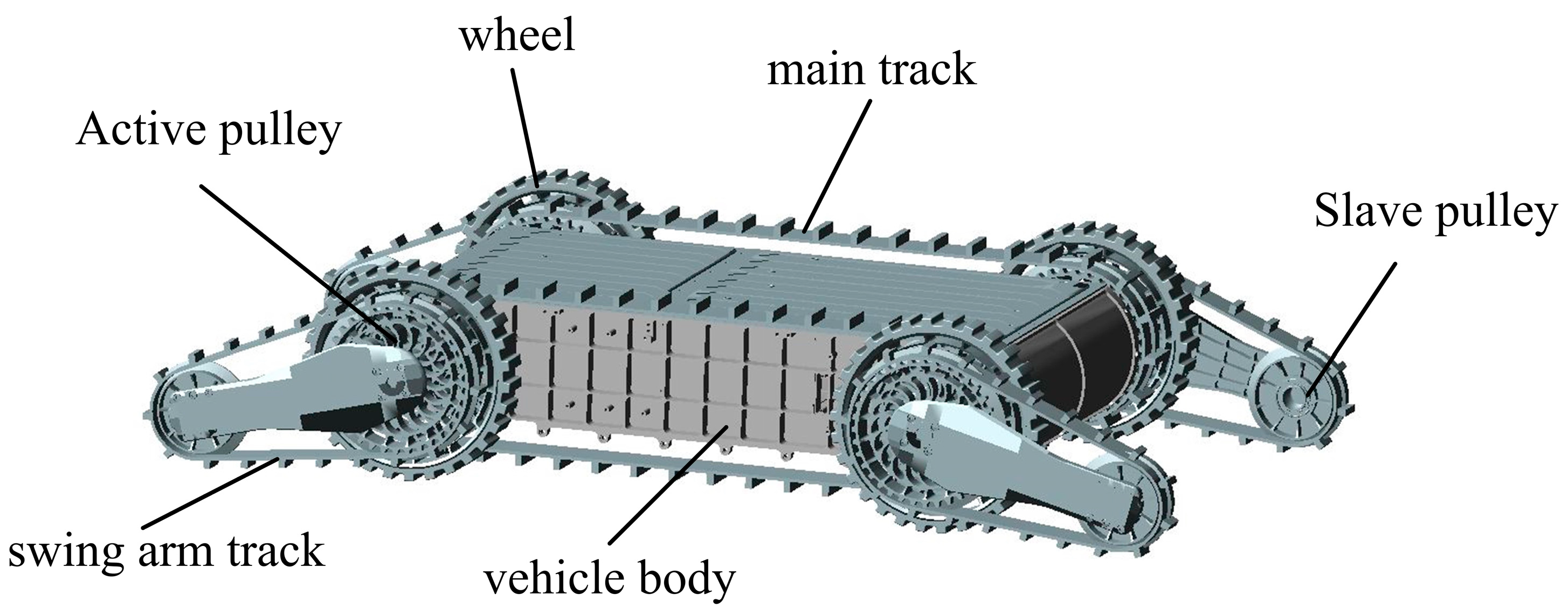
Integrating the characteristics of wheeled and tracked walking mechanisms, a multi-joint wheel-track composite mobile robot has been designed. It consists of four wheels, two intermediate tracks, and four swing arm tracks, which can ensure both the obstacle-crossing capability and rapid driving on flat ground. The mobile robot’s ability to cross barriers is related to the mechanism’s size, and the wheeled robot’s ability is limited by its wheel diameter. To overcome this limitation, the design idea of a folding and deforming mechanism is adopted to allow the robot to fold in a non-working state for storage and transportation. When it is in a working state, the robot unfolds, expanding in size, and thus achieving its obstacle-crossing function. The wheel-tracked composite robot is shown in
Figure 1.
Compared to the design in the literature [
10], our robotic platform has undergone significant improvements. One of the major changes we made was to adopt a pendulum wheel design with different sizes between the front and rear. This design enhances the flexibility and operability of our robot, enabling it to traverse over obstacles and uneven terrain more effectively. Moreover, we configured the front and rear pendulum wheels on the same axis, which further enhances the stability and control of our platform. These changes were carefully designed to optimize the performance of our robot while meeting specific application requirements.
When the robot is running normally, the track swing arm is in a retracted state, and the wheels are in contact with the ground for land travel. This feature makes it ideal for driving on flat roads, allowing for fast and efficient movement. However, when the robot encounters obstacles, its gait can be changed by any angle combination between the front and rear swing arms. This allows the robot to cross obstacles easily and with flexibility.
The swingarm is a crucial component of the robot’s capability to overrun and should be designed in a way that maximizes its overrunning ability without compromising the robot’s flexibility by making the arm too bulky. The robot tracks should feature a high coefficient of friction, which will enable the robot to traverse slippery dirt surfaces. Moreover, pendulum arms are designed to provide the robot with stability when moving across uneven and slippery terrain. The arms counterbalance the robot’s movement, preventing it from tipping over and ensuring a smooth gait. These design features serve to improve the robot’s efficiency and reduce the likelihood of damage to its components. With these considerations in mind, the robot’s pendulum arms are designed, as shown in
Figure 2, each of which can be rotated 360° to adjust the robot’s walking posture. With these design features, the robot has a higher chance of successfully traversing rough terrains and overcoming obstacles, making it a highly useful tool for search and rescue operations, exploration, and military applications.
5. Simulation and Numerical Calculation
Based on the analysis and our task requirements, we have carefully designed and developed a robot for urban environments. To gain a better understanding of the robot’s performance, we have listed its relevant parameters in
Table 1. The robot we have manufactured is shown in the following,
Figure 12.
Substitute the parameters of the robot into Equations (4)–(19). After calculation, for the robot climbing low steps, it reaches the maximum height of climbing As for climbing high steps, the maximum height of the robot climbing high step is mm. For the height of the robot platform overturning, the maximum overturning height is . Thus, the robot’s maximum step climbing height is 505.3 mm. When the height is below 206.65 mm, the robot adopts the first gait to improve climbing efficiency. For heights exceeding 206.65 mm, the second gait is used to maximize the climbing ability.
Figure 13a shows the curve of the swing arm track’s effective radius
and
, when the robot climbs a low step. The intersection of the two curves is the maximum height the robot can climb under a low step.
Figure 13b shows the surface plot of the swing arm’s effective radius
and step height
, when the robot climbs a high step. The highest point on the intersection line of the two surfaces is the maximum height that the robot can climb under the high step.
Figure 13c shows the surface plot of the relationship between the overturning height of the robot and the angle of the swing arm track. The highest point on the surface corresponds to the maximum height that the robot can overturn.
The virtual prototype of the wheel-tracked robot and the obstacle model were created in the three-dimensional modeling software Unigraphics NX 8.0 and imported into ADAMS. The four main wheels of the robot and the ground were set as the contact collision type, and the dynamic friction and static friction coefficients were redefined so that the robot wheels can contact the road and generate sufficient friction for movement. This allowed for the robot model movement on the road. The initial simulation settings and obstacle parameter settings are listed in
Table 2.
The linear motion speed curve of the robot is shown in
Figure 14. The model of the robot undergoes a linear acceleration process within 0.4 s after startup. The model can fully drive into the simulated road surface after 1.2 s of trial calculation because of the non-excitation road surface at the beginning of driving. After approximately 0.41 s, the robot mobile reaches its maximum motion speed and enters a uniform linear motion state. The robot ultimately meets the preset requirement of 1 m/s.
The simulation of the robot climbing a step with a height of 300 mm is shown in
Figure 15. The robot first approaches the step at a steady speed. Then, the rear swing arm rotates clockwise to raise the robot’s body, and the front swing arm rotates clockwise to contact the step. As the robot advances, the rear swing arm rotates clockwise, and the robot lifts until it successfully crosses the high step. Overall, the simulation demonstrates the robot’s ability to climb steps with ease and accuracy. The use of swing arms and the coordinated motion of the robot’s body allowed it to elevate itself and cross the step effectively. This proves the effectiveness of our gait planning. Future work can focus on enhancing the robot’s ability to climb higher steps and improving its stability during the climbing process.
Substitute the parameters of the robot into Equations (21)–(26). When the tubber timing belt drives on a smoother road surface (without considering the influence of track spurs on the size of adhesion force), the adhesion coefficient f can be taken as 0.7, or, when the rubber timing belt drives on the road surface with higher friction, the adhesion coefficient can be taken as 1.2. According to the calculation, the maximum slope angle of the robot in longitudinal climbing is γ = 35° for an attachment coefficient of 0.7 and for an attachment coefficient of 1.2.
Substitute the parameters of the robot into Equations (27)–(31). According to the calculation, the maximum slope angle of the robot in longitudinal climbing is γ = 35° for an attachment coefficient of 0.7 and for an attachment coefficient of 1.2. Establish the slope climbing simulation model of the mobile robot.
The process of the robot’s ascent up a slope of 30° has been simulated, and the simulation findings are elaborated in
Figure 16. The initial scenario in
Figure 16a shows the robot moving along steadily at a consistent speed prior to reaching the slope. During this stage, the robot’s swing arm is held in a contracted state. Moving on to the subsequent stage in
Figure 16b, the robot is depicted in an open swing arm state, negotiating the 30° slope. Additionally, the trajectory of the robot while it climbs up the slope is illustrated in
Figure 17. When observing
Figure 17, we can see that, from 0 to 0.66 s on the time axis, the robot was driving on a flat surface until it reached the slope position. At 0.66 s, the robot started to climb the stairs, and at 1.09 s, the robot had fully entered the slope and continued to travel on it.
Substitute the robot’s parameters into Equation (20). According to the calculation, when , the maximum width of the transverse trench m. Now, establish a simulation model of the robot that can cross the trench.
The simulation of the robot crossing the trench is shown in
Figure 18. Initially, the robot moves at a constant speed to the near edge of the trench and subsequently enters the crossing phase with its front wheels in suspension and the front swing arm touching the far edge of the trench. Then, the front swing arm crosses the distal edge line of the trench, straddles the trench, and the front drive wheels move from the original overhang to the distal edge line of the trench. The robot proceeds to move forward, while its rear drive wheels remain suspended near the side edge line of the trench. The rear pair of drive wheels of the robot moves from the overhang to the far side edge line, and the rear pair of swing arms begin to enter the overhang. Ultimately, the robot is positioned fully on the side of the distal edge line of the trench, successfully crossing it. The trajectory of the robot crossing the trench centroid is shown in
Figure 19. It can be observed from the figure that the robot is capable of smoothly crossing the trench.
6. Conclusions
In this paper, we specifically designed a composite mobile robot with both wheeled and tracked structures. We planned corresponding gaits for it and analyzed its performance in climbing stairs, slopes, and crossing ditches. The research results are as follows.
- (1)
Based on the change rule of the robot’s center of mass, we planned stair-climbing gaits for different terrains. The maximum climbable height is 505.3 mm; if it is less than 206.65 mm, the first gait is used; otherwise, the second gait is adopted.
- (2)
For slope climbing, we analyzed the platform torque changes and anti-skid conditions of the robot. When the adhesion coefficient is 0.7 and 1.2, the maximum longitudinal and lateral climbing angles are 35° and 50.2°, respectively.
- (3)
We studied the geometric relationship between the robot’s center of mass and the ditch during the ditch-crossing process, and we concluded that the maximum passable ditch width is 388.05 mm.
- (4)
The simulation validation shows that the robot can successfully complete tasks, such as climbing stairs, going uphill, and crossing ditches and ravines, proving the effectiveness and rationality of the planned gait.
In future work, we will conduct in-depth research on robot performance, including three-dimensional analysis, to fully understand its performance in complex environments. We will focus on the coordinated operation at different heights in obstacle scenarios and explore other influencing factors to optimize the gait planning, improve the stability and adaptability of practical applications. In summary, we will analyze and validate from multiple perspectives, aiming to achieve effective robot applications in various environments.


