Article

A Robust Control Strategy for the Automatic Load Commutation Device Considering Uncertainties of Source and Load

1
College of Electrical Engineering, Zhejiang University, Hangzhou 310027, China
2
State Grid Hangzhou Power Supply Company, Hangzhou 310016, China
3
School of Information and Electrical Engineering, Hangzhou City University, Hangzhou 310015, China
4
School of Information Science and Engineering, Zhejiang Sci-Tech University, Hangzhou 310018, China
*
Author to whom correspondence should be addressed.
Appl. Sci. 2023, 13(13), 7390; https://doi.org/10.3390/app13137390
Submission received: 15 May 2023 / Revised: 9 June 2023 / Accepted: 13 June 2023 / Published: 21 June 2023
(This article belongs to the Section Electrical, Electronics and Communications Engineering)

Abstract

:
The long-term three-phase imbalance in distribution systems can lead to increased energy losses during transmission, reduced efficiency in energy utilization, and have serious implications for power supply security, power quality, and economic operations of the power system. The automatic load commutation device is an automatic device designed to address the issue of three-phase load imbalances in low-voltage distribution networks. By adjusting the phase of users without interrupting the power supply, this automatic device evenly distributes the load across all phases and effectively resolves the three-phase imbalance problem. Therefore, aiming at the above issue, a robust optimization method is adopted to address the control problem of automatic load commutation devices for a low-voltage distribution network. First, using historical data from photovoltaic and wind power generation systems as well as user load, a forecast analysis is conducted and uncertainty models for renewable energy and load demand are established. Then, a robust control strategy for the automatic load commutation device is proposed, which considers uncertainties of both source and load using the robust optimization method. The proposed model is then linearized using second-order cone technology and strong dual theory, and the column-and-constrained generation (C&CG) algorithm is employed to solve the problem iteratively. Finally, a modified IEEE 33-bus system is taken to verify the effectiveness of the proposed strategy. The simulation results show that the proposed load commutation device robust control model can enhance the ability of the distribution network to respond to load demand and renewable energy fluctuations while ensuring the economic operation of the distribution network. In addition, by adjusting the deviation amount and uncertainty parameters of load demand and renewable energy, a good balance between the robustness and economy of the proposed model can be achieved.

1. Introduction

As the demand for power quality from distribution network users increases, power quality has become a pressing concern for the power system. In recent years, improving power quality in low-voltage distribution networks has been a major focus for the power system in China. One critical research topic is to identify and mitigate three-phase load imbalances in low-voltage distribution networks in order to enhance network management. However, distribution networks are challenging to manage due to their vast geographic spread, complex loads, and numerous single-phase loads with strong randomness and unbalanced spatiotemporal distributions. These factors can lead to three-phase imbalance phenomena in distribution systems [1,2,3], causing increased energy losses during transmission, reduced electric energy utilization efficiency, and severe consequences on power supply security, power quality, and the economic operation of the power system. Therefore, it is essential to adjust the phase sequence in low-voltage station areas not only to conserve energy and reduce losses within distribution networks but also to ensure the efficient use of electric energy [4,5].
Currently, the primary solutions for addressing the three-phase load imbalance issue in distribution systems include manual phase adjustment, reactive power compensation [6], asymmetric compensation, and distribution system controller management [7,8]. Reactive power compensation and asymmetric adjustment can partially improve the performance of distribution transformers. However, they cannot effectively solve the three-phase imbalance issue in distribution system lines. The manual phase adjustment and automatic commutation via smart commutation switches are the principal methods for regulating unbalanced loads in distribution systems. The manual phase adjustment involves manually adjusting the phase sequence of three-phase load access using power system operators to address unbalanced three-phase load distribution issues in distribution systems. This approach is time-consuming, labor-intensive, and unable to timely track load fluctuations, thus limiting its application scenarios. With the maturation of automatic load commutation device technology and decreasing equipment costs, automatic commutation devices have been widely adopted and applied in recent years. Nonetheless, with the increasing penetration of renewable energy sources within the distribution network [9], there has been a growing proportion of nonlinear and impact loads, leading to changes in power supply concerning both magnitude and direction on transmission lines. Therefore, it is crucial to study reasonable control strategies for automatic load commutation devices that fully consider uncertainties related to renewable energy output and load demand within the power system.
In order to ensure the relative balance of loads distributed across three phases to reduce line loss, numerous scholars have conducted research on load commutation algorithms and the uncertainty of user loads. In [10], a load adjustment method based on the historical power data for each phase in the distribution system and the electricity consumption information of each user in the substation is proposed. This approach avoids misadjustment problems caused by the access or fluctuations of transient random loads when adjusting the load through on-site current detection. A three-phase unbalance mitigation model considering the three-phase unbalance degree is proposed in [11], and a mixed-integer linear programming model is formulated. In [12], a load commutation strategy that considers the threshold of a three-phase imbalance is proposed to alleviate the phenomenon of three-phase load imbalances in distribution systems effectively. In [13], a multi-objective optimal load commutation mathematical model with the optimization objective of minimizing both three-phase current imbalance in distribution systems and automatic load commutation device switching times during the commutation process is established to improve the economic operation levels of a power system. In [14], the impacts of different loads and electricity usage patterns on single-phase power users are considered, and a method for addressing three-phase imbalances of distribution systems based on load dynamic programming is proposed. In [15], a manual phase sequence optimization method based on load forecasting and a nondominated sorting genetic algorithm is suggested, which alleviates delays and lags within algorithms when allocating phase sequences using collected historical data, ultimately achieving positive energy-saving effects. In [16], a multi-objective optimization model with objectives including minimizing three-phase imbalances, minimizing commutation times, and maximizing phase sequence continuity duration is established. This approach can help to prevent continuous commutations over multiple time periods while enhancing adaptability for commutation switch adjustments in response to user-load fluctuations.
Based on the references mentioned above, it can be seen that significant progress has been made in the field of control strategies for load commutation devices and addressing three-phase load imbalance in distribution systems. However, current research on control strategies for load commutation devices primarily focuses on multi-objective optimization models with the objective of minimizing the degree of three-phase imbalance or minimizing the number of load commutations. Furthermore, the above references did not consider the redistribution of power flow after grid reconstruction when constructing phase optimization models. Thus, this paper intends to incorporate uncertainties in user load demand and renewable energy output and investigate the robust control of automatic load commutation devices with the optimization objective of minimizing the cost of three-phase distribution network line loss and load commutation.
Therefore, an automatic load commutation device robust control model considering the uncertainties of both renewable energy output and the load demand in three-phase unbalanced distribution network is established in this paper. Firstly, the model of renewable energy and load demand uncertainty is established based on the prediction analysis of the historical data of photovoltaic power systems, wind power systems and user loads. Then, a robust control strategy for an automatic load commutation device considering the uncertainties of both source and load is proposed based on the robust optimization method. The model is linearized by second-order cone technology and the strong dual theorem, and an iterative solution is obtained using column-and-constraint generation algorithm (C&CG). Finally, the modified IEEE 33-bus system is taken as an example to verify the effectiveness of the proposed strategy.

2. The Uncertainty Models of Renewable Energy and Load Demand

2.1. The Model of Uncertainty for the Output of Photovoltaic Power Generation System

The intensity of illumination can have a significant impact on the active power provided by a photovoltaic power generation system. By predicting the intensity of illumination in the environment where the photovoltaic system is located, the predicted value of the active power output P p v of the photovoltaic system can be represented as:
P p v = H A η K
where H is the predicted local light intensity value; A is the area of photovoltaic system; η is the conversion efficiency of photovoltaic modules; and K is the correction coefficient, including the operational attenuation coefficient, inverter efficiency, correction factor for photovoltaic system orientation, etc.
Considerable empirical statistical evidence demonstrates that the illumination level during a specific time period conforms closely to the Beta distribution [17], and its corresponding probability density function can be approximated as follows:
f ( x ; α , β ) = Γ ( α + β ) Γ ( α ) Γ ( β ) x α 1 ( 1 x ) β 1
where α and β are the shape parameters of the Beta distribution, which can be calculated from the mean and variance of the intensity of illumination over a certain time period. Γ( ) is the gamma function. x is the ratio of illumination intensity to the maximum illumination intensity, which is defined as:
x = r r max
where r max denotes the maximum illumination intensity at a certain time period.
After considering the uncertainty of photovoltaic power, the active power output of the photovoltaic system and the maximum deviation of the active power output can be obtained. Then, the active power output of the photovoltaic system can be represented as
P U p v = P p v + P D p v ε p v
where P U p v is the active power output of photovoltaic system considering the uncertainty, P p v is the predicted active power output of the photovoltaic system, P D p v is the maximum deviation of the active power output of the photovoltaic system, and ε p v is the fluctuation degree of the photovoltaic output.

2.2. The Model of Uncertainty for the Output of Wind Power Generation System

Wind speed is the main factor affecting the output of the wind turbine generator system. By predicting the wind speed of wind power farms, the predicted value P w t , the active power provided by wind power generation system, can be represented as [18]:
P w t = 0 0 v v c   or   v v f P r v v c v r v c v c v v r P r v r v v f
where P r is the rated output power of the wind power generation system, and v , v r , v c and v f are the predicted wind speed, rated wind speed, cut-in wind speed, and cut-out wind speed, respectively.
Typically, lots of scholars employ various distributions, such as the Weibull distribution, normal distribution, and Rayleigh distribution, to model the probability density function of wind speed. In this work, the well-established bimodal Weibull distribution [19] is adopted to characterize the probability density of wind speed, and its corresponding probability density function can be represented as follows:
f v w i n d = k s h a p e c s c a l e v w i n d c s c a l e exp v w i n d c s c a l e k s h a p e
where kshape and cscale are the shape parameter and distribution parameter of f(vwind), respectively.
According to the wind speed probability model and the wind power generation model, the active power output and the maximum deviation of the active power output of the wind power generation system can be obtained. Then, the active power output of the wind power generation system considering the uncertainty can be represented as:
P U w t = P w t + P D w t ε w t
where P U w t is the active power output of wind power considering the uncertainty, P w t is the forecasted active power output provided by the wind power generation system, P D w t is the maximum deviation of the actual wind power generation active power value relative to the active power forecast output, and ε w t is the fluctuation degree of the wind power output.

2.3. The Model of Uncertainty for Load Demand

A long- and short-term memory neural network [20] is utilized in this work for load demand prediction, the active power demand and reactive power demand can be represented as:
P U L , t = P L , t + P D L , t ε L Q U L , t = Q L , t + Q D L , t ε L
where P U L , t and Q U L , t are the active and reactive power demands of the load considering uncertainty, respectively; P L , t and Q L , t are the predicted values of active and reactive power of the load at time t, respectively; P D L , t and Q D L , t are the maximum deviation of the actual active power and reactive power of the load relative to the predicted value, respectively; and ε L is the fluctuation degree of load demand.

3. The Robust Control Model of Automatic Load Commutation Devices Considering the Uncertainties of Source and Load

3.1. The Objective Function of the Robust Control Model for Automatic Load Commutation Devices

Radial distribution networks are commonly structured to adopt a radial configuration for zone power supply, which poses a challenge in the planning of such networks. Therefore, selecting appropriate power flow equations that are specifically designed for calculating radial distribution networks is imperative. In this work, the Distflow model for branch power flow [21] is utilized to describe the power flow in radial distribution networks. Accounting for the uncertain factors of the distribution system, an enhanced Distflow model for branch power flow in three-phase unbalanced radial distribution networks can be represented as follows:
For any node j at time t,
i m ( j ) P i j φ , t r i j φ P i j φ , t 2 + Q i j φ , t 2 V i φ , t 2 = k n ( j ) P j k φ , t + P j φ , t i m ( j ) Q i j φ , t X i j φ P i j φ , t 2 + Q i j φ , t 2 V i φ , t 2 = k n ( j ) Q j k φ , t + Q j φ , t P j φ , t = P U j , D G φ , t P U j , L φ , t Q j φ , t = Q U j , D G φ , t Q U j , L φ , t
For the branch ij at time t,
V i φ , t 2 V j φ , t 2 = 2 P i j q , t i j + Q i j φ , t x φ r i j φ 2 + x i j φ 2 P i j φ , t 2 + Q i j φ , t 2 V i φ , t 2
where φ { A , B , C } , m(j) denotes the set of initial nodes of the branch in the grid with node j as the terminal node; n(j) denotes the set of terminal nodes of the branch in the grid network with node j as the initial node; P i j φ , t and Q i j φ , t are the active and reactive power of each phase of the initial end of branch ij, respectively; r i j φ and x i j φ are the three-phase branch resistance and reactance of branch ij, respectively; V i φ , t is the voltage amplitude of each phase of node i; P j φ , t and Q j φ , t are the net active and reactive power injections of each phase at node j, respectively; P U j , D G φ , t and Q U j , D G φ , t are the renewable energy active and reactive power values at node j, respectively; and P U j , L φ , t and Q U j , L φ , t are the load active and reactive power demands, respectively.
According to the Distflow model for branch power flow, node voltage and power flow from the source node to the terminal node of the distribution network can be incrementally calculated. To accommodate the uncertainty of renewable energy and load demand, this paper aims to minimize the total line loss for three-phase systems to ensure maximum profit in worst-case scenarios. In addition, considering the impact of frequent switching actions of load commutation switches on their service life, this paper incorporates the cost of switching actions into the objective function. Therefore, a robust control model for automatic load commutation devices is developed in this paper, which accounts for uncertainties in both source and load, with an objective function that seeks to minimize the total line loss for three-phase systems and costs associated with commutation switch actions. The objective function is represented as follows:
min t T i F C a c t α i , t + max P ˜ j , D G φ , t , P ˜ j , L φ , t , Q ˜ j , L φ Π 1 2 t T φ = A C i = 1 N b j c ( i ) C l o s s r i j φ P i j φ , t 2 + Q i j φ , t 2 V i φ , t 2
where T is the time set, F is the set of nodes where the commutation switch is located; C a c t is the cost coefficient of one action of the commutation switch; C l o s s is the unit price of active power consumed by the network loss; α i , t is the 0–1 variable of whether the load commutation switch is operated or not at node i at moment t; α i , t = 1 means the load commutation switch is operated, otherwise it is 0; Π denotes the uncertainty set of renewable energy and load demand at moment t; N b is the set of nodes in the distribution network; and c(i) is the set of nodes connected to node i in the distribution network.

3.2. The Constraints of the Robust Control Model for Automatic Load Commutation Devices

(1)
Constraints on power balance
In the robust control model of automatic load commutation considering the uncertainties of source and load, the power balance constraints are shown as Equations (1) and (3).
(2)
Security constraints on node voltage and branch current
To ensure the secure and stable operation of a low-voltage distribution network that considers the uncertainty of renewable energy and load demand, the node voltage and branch current must meet the following constraints
V i φ , min V i φ V i φ , max I i j φ I i j φ , max
where V i φ , min and V i φ , max denote, respectively, the φ-phase minimum and maximum voltage limits for node i, and I i φ , max is the limit of the overload critical current of the φ-phase branch.
(3)
Constraint on the output power of root node
The uncertainty of load demand and renewable energy will cause power fluctuations in the distribution network and adversely affect the transmission network, so the gateway exchange power at the root node of the distribution network must meet the following constraints:
P 0 φ , min P 0 φ P 0 φ , max Q 0 φ , min Q 0 φ Q 0 φ , max
where P 0 φ and Q 0 φ , respectively, represent the active power and reactive power of phase φ flowing into the distribution network from the root node, and P 0 φ , min , P 0 φ , max , Q 0 φ , min , and Q 0 φ , max are, respectively, the upper and lower limits of the active power and reactive power at the junctions of phase φ.
(4)
Constraint on the number of commutation switch operations
In order to minimize the impact of the commutation switch operation on its service life and to ensure the normal operation of the switch during the optimization period, the number of commutation switch operations should meet the following constraint:
t T i F a i , t < S max
where S max   is the maximum number of all commutation switch operations during the optimization period.
(5)
Constraints on the power fluctuations of renewable energy and load demand considering the uncertainties
P i , D G φ , t = P U i , D G φ , t Q i , D G φ , t = P U i , D G φ , t tan γ P U i , D G φ , t P i , t G φ , t P D i , D G φ , t , P i , D G φ , t + P D i , D G φ , t Q U i , D G φ , t Q i , D G φ , t Q D i , D G φ , t , Q i , D G φ , t + Q D i , D G φ , t P U i , L φ , t P i , L φ , t P D i , L φ , t , P i , t φ , t + P D i , L φ , t Q U i , L φ , t Q i , L φ , t Q D i , L φ , t , Q i , L φ , t + Q D i , t φ , t k n ( i ) ε i , D G φ , t Γ D G N D G k n ( i ) ε i , L φ , t Γ L N L
where P U i , D G φ , t and P U i , L φ , t are the active power output of renewable energy and photovoltaic power considering the uncertainty at time t, respectively; γ is the power factor angle; P i , D G φ , t and P D i , D G φ , t are the predicted output and fluctuation of active power of renewable energy at time t, respectively; P i , L φ , t , P D i , L φ , t , Q i , L φ , t , and Q D i , L φ , t are the predicted output and fluctuations of active and reactive power of load demand at time t, respectively; ε i , D G φ , t and ε i , L φ , t are the fluctuation degrees of renewable energy and load demand, respectively; Γ D G and Γ L are the uncertainty parameters of renewable energy and load demand, respectively; and N D G and N L denote the number of renewable energy and load with uncertainty, respectively.
In the steady-state analysis process of distribution networks, renewable energy sources typically employ the PQ control mode [22]. This implies that the reactive power provided by photovoltaic and wind turbine units can be computed based on the known active power and power factor.

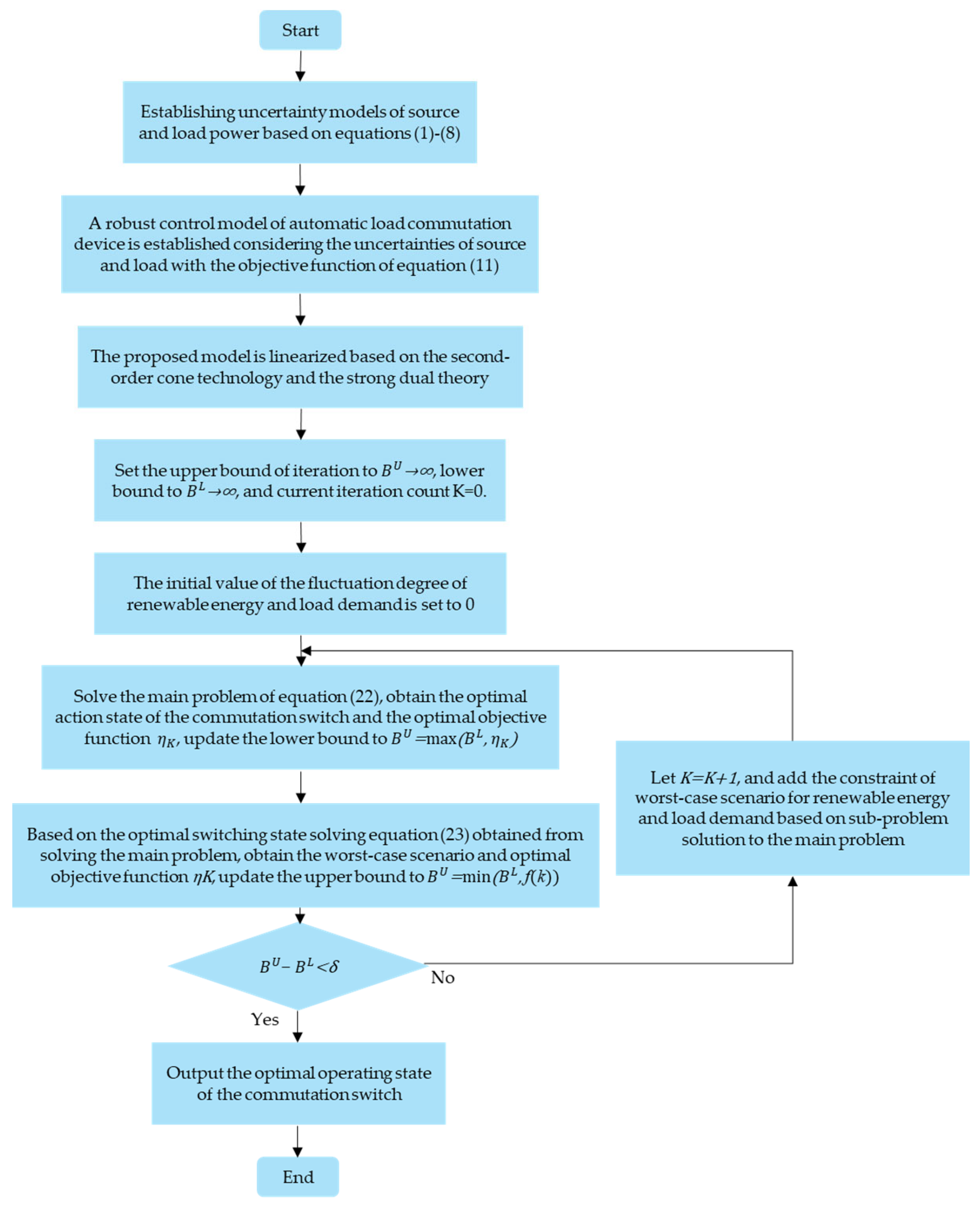
3.3. Solution Algorithm for the Robust Control Model

Due to the nonlinearity and strong non-convexity of the power balance constraint in the robust control model of automatic load commutation devices in the distribution network, as well as the discrete integer variable constraint on the number of switching actions, the model is a mixed-integer nonlinear programming problem with NP-hard characteristics, which is difficult to solve. To address this issue, the convex relaxation based on second-order cone programming is utilized in this paper to transform the original optimization model into a mixed-integer convex programming model, which considers the characteristics of distribution networks. The optimized model after convex relaxation exhibits improved computational efficiency compared to its original version. Then, the intermediate variables are defined for the voltage magnitude squared and current magnitude squared as follows:
v i , 2 φ , t = V i t 2 i i j , 2 φ , t = P i j φ , t 2 + Q i j φ , t 2 V i φ , t 2
Using the above variables to replace the relevant terms in the original objective function and constraints, the objective function can be represented as:
min t T i F C a c t α i , t + max P ˜ j , D G φ , t , P ˜ j , L φ , t , Q ˜ j , L φ Π 1 2 t T φ = A C i = 1 N b j c ( i ) C l o s s r i j φ i i j , 2 φ , t
Then, add i i j , 2 φ , t = P i j φ , t 2 + Q i j φ , t 2 V i φ , t 2 to the constraints. According to references [23,24], under the conditions of the objective function being a strictly increasing function and there being no upper bound on the node load, the above equation can be transformed into:
i i j , 2 φ , t P i j φ , t 2 + Q i j φ , t 2 v i , 2 φ , t
After an equivalent transformation, Equation (18) can be written in standard second-order cone form as follows:
2 P i j φ , t 2 Q i j φ , t i i j , 2 φ , t v i , 2 φ , t i i j , 2 φ , t + v i , 2 φ , t
The constraint on power balance can be changed into the following form:
i m ( j ) P i j φ , t r i j φ i i j , 2 φ , t = k n ( j ) P j k φ , t + P j φ , t i m ( j ) Q i j φ , t x i j φ i i j , 2 φ , t = k n ( j ) Q j k φ , t + Q j φ , t v i , 2 φ , t v j , 2 φ , t = 2 P i j φ , t r i j φ + Q i j φ , t x i j φ r i j φ 2 + x i j φ 2 i i j , t φ , t 2 P i j φ , t 2 Q i j φ , t i i j , 2 φ , t v i , 2 φ , t i i j , 2 φ , t + v i , 2 φ , t P j φ , t = P U j , D G φ , t P U j , L φ , t Q j φ , t = Q U j , D G φ , t Q U j , L φ , t
Through the transformation above, the robust control model of automatic load commutation device considering the uncertainties of source and load is transformed into a second-order cone programming problem, which can be represented as follows:
min t T i F C a c t α i , t + max P ˜ j , D G φ , t , P ˜ j , P φ , t , Q ˜ j , L φ 1 2 t T φ = A C i = 1 N b j c ( i ) C l o s s r i j φ i i j , 2 φ , t   s . t .   ( 12 ) ( 15 ) ,   ( 20 )
Extensive research has been conducted on the effectiveness of second-order cone transformation, as documented in reference [25]. It shows that under certain assumptions, the accuracy of the model can be ensured while obtaining optimal solutions to the original problem.
The robust control model established above for the automatic load commutation devices considering the uncertainties of source and load is a two-layer model. Taking uncertainty into account, the decision variable of the outer layer is the number of operations for the automatic load commutation device, while the decision variables of the inner layer include load demand and renewable energy output. In this way, the original problem cannot be solved directly. From the mathematical form of the model, it can be seen that the robust control model for an automatic load commutation device is a combinatorial optimization problem typically solved using approximate algorithms based on mathematical programming. When determining the number of actions for all automatic commutation devices, this problem can be transformed into an optimal power flow problem to establish load demand and renewable energy levels. Utilizing the C&CG algorithm [26], the original uncertain robust problem can be converted into a main problem and a subproblem for iterative solution. This algorithm presents superior computational efficiency and solution performance. The main issue above considers the operating status of automatic commutation switches within an optimized network throughout the entire optimization period in order to reduce switch operation costs; meanwhile, based on current automatic load commutation switch states, the subproblem calculates optimal network loss under worst-case scenarios involving fluctuations in renewable energy and load demand under uncertain conditions.
The main problem of the two-stage robust control model for automatic load commutation devices considering the uncertainties of source and load can be represented as:
min t T i F C a c t α i , t + η s . t .   η 1 2 t T φ = A C i = 1 N b j c ( i ) C l o s s r i j φ i i j , 2 φ , t i m ( j ) P i j φ , t r i j φ i i j , 2 φ , t = k n ( j ) P j k φ , t + P j , D G φ , t , S P j , L φ , t , S i m ( j ) Q i j φ , t x i j φ i i j , 2 φ , t = k n ( j ) Q j k φ , t + Q j , D G φ , t , S Q j , L φ , t , S v i , 2 φ , t v j , 2 φ , t = 2 P i j φ , t r i j φ + Q i j φ , t x i j φ r i j φ 2 + x i j φ 2 i i j , 2 φ , t 2 P i j φ , t 2 Q i j φ , t i i j , 2 φ , t v i , 2 φ , t i i j , 2 φ , t + v i , 2 φ , t ( 12 )   -   ( 14 )
where P j , D G φ , t , S , Q j , D G φ , t , S , P j , L φ , t , S , and Q j , L φ , t , S are the active and reactive power of renewable energy and load demand, respectively, which are obtained by solving the subproblem.
The main problem is the optimization problem in the first stage. In the main problem above, variables for renewable energy and load demand in Equation (20) have been replaced with worst-case power values returned by corresponding subproblems under conditions such as the constraint on power balance, the constraint on the node voltage and branch current safety, the constraint on the output power of root node, the constraint on the commutation switch’s frequency. The main problem can be solved to obtain optimal operating states of automatic commutation device for each load. It is a mixed-integer linear programming problem and can be easily solved using commercial solvers.
The subproblem of the two-stage robust control model of the automatic load phase change device considering the uncertainties of both source and load can be represented as:
max min 1 2 t T φ = A C i = 1 N b j c ( i ) C loss   r i j φ i i j , 2 φ , t   s . t .   ( 12 ) ( 13 ) ,   ( 15 ) ,   ( 20 )
The subproblem is the second stage of the aforementioned two-stage robust control model of the automatic load phase change device. In this problem, the operating state of the automatic commutation device is a known variable that is determined by solving the main problem. Therefore, while considering the uncertainties associated with renewable energy and load demand, the subproblem solves the optimal three-phase power flow that minimizes the loss of the distribution network under worst-case scenarios, given the operating state of the commutation device.
The subproblem serves to generate new scenarios for renewable energy and load demand, which are then included as new column constraints in the main problem. Given a specific state of automatic commutation device action, solving the subproblem results in the corresponding optimal solution and the worst-case fluctuation scenario of renewable energy and load demand. Therefore, this subproblem can be formulated as a mixed-integer linear programming problem with the objective of maximizing the objective function.
The objective function of the subproblem is a min–max problem, which is difficult to solve directly. However, the subproblem can be transformed into a linear programming problem that satisfies the strong dual condition. Therefore, this paper takes the strong dual theory to transform the inner minimum value problem into its corresponding dual maximum value problem [27,28]. As a result, the inner and outer problems can be merged into one maximum problem while adding the corresponding dual constraint and complementary slackness constraint. The objective function of the subproblem after dual processing can be represented as:
max 1 2 t T φ = A C i = 1 N b j c ( i ) C l o s s r i j φ i i j , 2 φ , t
After the transformation above, both the main problem and subproblems become mixed-integer linear programming problems that can be solved iteratively using the C&CG algorithm. The subproblem continuously generates new column constraints and adds them to the main problem for iterative solving until the upper and lower limits converge to the optimal solution. The convergence accuracy of the algorithm is set as δ. The solving process of a robust control model for automatic commutation device in distribution network load based on the C&CG algorithm is shown in Figure 1.

4. Case Studies

4.1. Case and Parameter Settings

To verify the effectiveness of the model proposed in this paper, a robust control model of the automatic load commutation device considering the uncertainties of the source and load is established using MATLAB R2019b. Then, the commercial optimization solver CPLEX 12.9.0 is employed to solve the optimization model. The test environment utilizes an Intel Xeon Gold 5117 CPU with a clock speed of 2.00 GHz and 64 G RAM.
The topology of the modified IEEE 33-bus power system, used in this paper, is illustrated in Figure 2. The system comprises 33 nodes, 32 branches, a voltage level of 12.66 kV, and an installed capacity of 1 MVA. The photovoltaic systems have an installed capacity of 250 kVA and are installed at nodes 6 and 27 connected to phase A. Additionally, a photovoltaic system with an installed capacity of 250 kVA is installed at node 20 connected to phase C. Wind turbines with an installed capacity of 300 kVA are positioned at nodes 15 and 24 connected to phase B. The power factor for renewable energy sources is set at 0.8. The branch parameters and reference load data are based on information from reference [29] as presented in Table 1. The total active power and reactive power of the standard system are measured at approximately 3635 MW and 2265 Mvar, respectively. The difference in active power carried by each phase of the system’s load can reach up to a maximum difference of 30 kW, indicating the presence of a three-phase imbalance phenomenon.
The optimization period in this paper spans 24 h, which is divided into 24 equal time periods. The values of renewable energy and load demand at the beginning of each period are used as the numerical input. The unit price of active power consumption for distribution network loss and the cost coefficient for switching once are set to USD 0.8/kW·h and USD 1/time, respectively. The variation curves of the predicted output for the three-phase load and renewable energy are shown in Figure 3. To simulate the load demand and renewable energy output over the 24 h period, the original load at the node is multiplied by the corresponding change rate, and the capacity of renewable energy is multiplied by the same rate. It is worth noting that different change rates can be used without compromising the effectiveness of the proposed method.

4.2. Result Analysis for Robust Control Implementation in Automatic Load Commutation Devices

To demonstrate the effectiveness of the robust control model of automatic load commutation device, a user with an active power of 10 kW and reactive power of 4 kVar equipped with an automatic commutation device is added to each load node in the modified IEEE 33-bus system described above. Similarly, the original load is multiplied by the load change rate to obtain the user’s load values for changes within a 24 h period, and optimization simulations are conducted for both determinacy and robustness. The maximum deviation rate of active output from photovoltaic and wind power are set as 30%, and the maximum deviation rate of load demand is set as 40% [30]. Meanwhile, the deterministic model for the automatic load commutation device based on the predicted output of load demand and renewable energy used to solve the model is employed. Commutation operation occurs only once within a 24 h period, with the total network loss over one day being minimized. The uncertainty parameters Γ D G and Γ L of renewable energy and load demand are both set as 1. The robust control results of the automatic load commutation device are shown in Table 2, along with the deterministic control results.
From Table 2, it can be seen that the automatic load commutation devices in the deterministic model only performed one commutation action within a day, while in the robust control model, the automatic commutation device performed commutation actions four times within a day. In the deterministic model of an automatic load commutation device, the considered load demand and renewable energy are both predicted values, and the distribution network operates under ideal conditions. Therefore, its automatic load commutation device only needs a small number of actions to make the three-phase distribution network operate in a more balanced state. In contrast, the robust control model of automatic load commutation devices needs to consider the optimal operation of distribution network under worst-case scenarios for both load demand and renewable energy. The robust control model of automatic load commutation device aims to optimize the operation of the power distribution network under the worst-case scenarios of load demand and renewable energy. The network loss results obtained from the robust control model are the network losses under the worst-case scenarios of the power injections at node, so the total three-phase network loss is higher than that of the deterministic model.
In addition, in order to demonstrate that the robust control model with an automatic load commutation device will not significantly affect the economic efficiency of the distribution network, Table 3 compares the objective function values of the deterministic model and robust control model under the predicted power scenario and the worst-case scenario with fluctuating load demand and renewable energy.
According to Table 3, when the load demand and renewable energy are in the predicted power output scenario, the objective function value of the robust control model for the automatic load commutation device is slightly higher than that obtained by the deterministic model. This is due to the robust control model taking the situation of load demand and fluctuations in renewable energy into account, thus sacrificing some of the operational economic efficiency of the distribution network. When the load demand and renewable energy are at their worst-case scenario, the objective function value of the robust control model is significantly lower than that of the deterministic model, which proves the necessity of considering fluctuations in load demand and renewable energy. Meanwhile, the comparison of objective function values shows that the robust control model of the automatic load commutation device does not sacrifice too much economic efficiency in the operation of the distribution network. On the contrary, it can enhance the ability of the distribution network to cope with load demand fluctuations and improve its acceptance capacity for renewable energy.

4.3. Sensitivity Analysis of Parameters within Uncertainty Sets

The range of uncertainty in the source and load considered in this paper is influenced by the maximum deviation and fluctuation in the prediction of load demand and renewable energy. To analyze the impact of parameter changes in uncertain sets on model conservatism, this section utilizes a modified IEEE 33-bus power system to conduct the sensitivity analysis. Different deviation and uncertainty parameters are set for load demand and renewable energy, respectively, to compare the effects of robust control model and deterministic model on optimization results.
For the sake of comparison, only the uncertainty caused by a single factor is considered. Specifically, it assumes that renewable energy remains at its predicted value while load demand varies within a range of 10% to 40% above the predicted value. Alternatively, it assumes that load demand stays at its predicted value while renewable energy varies within a range of 10% to 30% above the predicted value. The corresponding objective function values for the system are presented in Table 4.
From Table 4, it can be seen that when the deviation of load demand is higher than that of the predicted value, the objective function value of the robust control model is lower than that of the deterministic model. As the uncertainty of load demand increases, the difference in objective function values between the two models increases and the optimization effect of robust control model is better, reflecting its advantage in adverse scenarios. Conversely, when the deviation of renewable energy surpasses the predicted value, the objective function value of the deterministic model is lower than that of the robust control model. This occurs due to the power injections from renewable energy sources having an opposite effect compared to that of load demands. As renewable energy generation increases, simulation conditions shift towards more favorable scenarios rather than worsening ones. The continuous absorption of connected renewable energy by loads reduces three-phase network losses. Consequently, in these situations, the optimization effect of a robust control model is slightly inferior to that of a deterministic model. It can be concluded that a robust control strategy offers better adaptability to harsh conditions without sacrificing significant economic efficiency within milder scenarios. Furthermore, this approach enhances a distribution network’s ability to respond effectively to uncertainties of both the source and load within its system.
The number of scenarios contained in the uncertainty sets of load demand and renewable energy will be affected by uncertainty. By controlling the uncertainty parameters, certain limitations can be imposed on the situation of load demand and renewable energy, thereby regulating the conservatism of the robust control model for automatic load commutation devices. This paper designs multiple combinations of renewable energy and load demand uncertainty parameters Γ D G and Γ L . The corresponding objective function values of the system under different uncertainty parameters are shown in Table 5. From Table 5, it can be seen that as the uncertainty parameters Γ D G and Γ L decrease, the range of the uncertainty set gradually becomes smaller, and the worst-case scenario covered by the generated fluctuation scene is reduced. Therefore, the optimized objective function value will also decrease accordingly, and the conservatism of the robust control model for the automatic load commutation device is reduced. In practical applications, decision-makers should consider the impact of objective factors, such as demand-side policies, on the fluctuation of load demand and renewable energy based on the actual distribution network situation. Based on this, they can choose appropriate uncertainty parameters, exclude certain extremely low probability adverse scenarios, and achieve a balance between robustness and economy in the control model of the automatic load commutation device.

5. Conclusions

While aiming at the uncertainties of renewable energy and load demand in a three-phase unbalanced distribution network, a robust control model of automatic load commutation devices considering the uncertainties of source and load is established in this paper. First, based on the historical data of photovoltaic power generation system, wind power generation system, and user load, a forecast analysis is carried out, and the uncertainty models of renewable energy and load demand are established. Then, based on the robust optimization method, a robust control strategy for the automatic load commutation device considering the uncertainties of both source and load is proposed. On this basis, the proposed model is linearized based on second-order cone technology and the strong dual theory to make it easier to be solved. Finally, taking the modified IEEE 33-bus system as an example, case studies are conducted to verify the effectiveness of the proposed strategy. The results verified the feasibility and effectiveness of the proposed method and show that the model proposed in this paper will sacrifice part of the economics of distribution network operation, but it has better adaptability to harsh scenarios and does not have too much economic loss in mild scenarios, which can strengthen the distribution network to cope with the uncertainty of source and load in the network. In addition, by adjusting the deviation and uncertainty parameters of load demand and renewable energy, the robustness and economy of the proposed model can be well balanced. The future work can be carried out from the following aspects:
(1)
The selection method of the optimal uncertainty is not considered in this work. The optimal uncertainty can be selected on the basis of the commutation strategy, reasonably reduce the size of the uncertainty set, and weigh the conservatism of the robust control.
(2)
The whole optimization cycle for optimization is taken as 24 h in this work, which reduces the number of actions of the commutation device. How to reasonably divide the commutation cycle of the load automatic commutation device within a day to further improve the economy of distribution system operation needs to be studied in the future.

Author Contributions

Conceptualization, Y.W., Z.C., T.Z. and Z.L.; methodology, Y.W. and Z.C.; software, Y.W. and Z.C.; validation, G.C.; formal analysis, Y.W. and Z.C.; investigation, G.C. and Z.C.; resources, G.C.; data curation, Y.M.; writing—original draft preparation, Y.W. and Z.C.; writing—review and editing, T.Z. and Z.L.; visualization, T.Z. and Y.M.; supervision, C.C. and Z.L. All authors have read and agreed to the published version of the manuscript.

Funding

This research was funded by the National Natural Science Foundation of China, grant number U2166206 and the National Natural Science Foundation of China, grant number 52077195.

Institutional Review Board Statement

Not applicable.

Informed Consent Statement

Not applicable.

Data Availability Statement

The data presented in this study are available from the first author upon request.

Conflicts of Interest

The authors declare no conflict of interest.

References

  1. Zahedmanesh, A.; Muttaqi, K.M.; Sutanto, D. An adaptable correlated control for maintaining voltage quality in low-voltage distribution grids containing PVs and PEVs. IEEE Trans. Ind. Inform. 2022, 18, 5804–5814. [Google Scholar] [CrossRef]
  2. Zhang, T.; Liu, S.; Qiu, W.; Lin, Z.; Zhu, L.; Zhao, D.; Qian, M.; Yang, L. KPI-based real-time situational awareness for power systems with a high proportion of renewable energy sources. CSEE J. Power Energy Syst. 2022, 8, 1060–1073. [Google Scholar]
  3. Liu, S.; You, S.; Lin, Z.; Zeng, C.; Li, H.; Wang, W.; Hu, X.; Liu, Y. Data-driven event identification in the US power systems based on 2D-OLPP and RUSBoosted trees. IEEE Trans. Power Syst. 2022, 37, 94–105. [Google Scholar] [CrossRef]
  4. Zhao, J.; Wang, Y.; Song, G.; Li, P.; Wang, C.; Wu, J. Congestion management method of low- voltage active distribution networks based on distribution locational marginal price. IEEE Access 2019, 7, 32240–32255. [Google Scholar] [CrossRef]
  5. Su, X.; Masoum, M.A.S.; Wolfs, P.J. Optimal pv inverter reactive power control and real power curtailment to improve performance of unbalanced four-wire lv distribution networks. IEEE Trans. Sustain. Energy 2014, 5, 967–977. [Google Scholar] [CrossRef]
  6. Ferreira, P.D.F.; Carvalho, P.M.S.; Ferreira, L.A.F.M.; Ilic, M.D. Distributed energy resources integration challenges in low-voltage networks: Voltage control limitations and risk of cascading. IEEE Trans. Sustain. Energy 2013, 4, 82–88. [Google Scholar] [CrossRef]
  7. Djerioui, A.; Houari, A.; Saim, A.; Ait-Ahmed, M.; Pierfederici, S.; Benkhoris, M.F.; Machmoum, M.; Ghanes, M. Flatness based grey wolf control for load voltage unbalance mitigation in three-phase four-leg voltage source inverters. IEEE Trans. Ind. Appl. 2020, 56, 1869–1881. [Google Scholar] [CrossRef]
  8. Chen, Y.; Lao, K.-W.; Qi, D.; Hui, H.; Yang, S.; Yan, Y.; Zheng, Y. Distributed self-triggered control for frequency restoration and active power sharing in islanded microgrids. IEEE Trans. Ind. Inform. 2023, 1–12. [Google Scholar] [CrossRef]
  9. Chu, Z.; Cui, X.; Zhai, X.; Liu, S.; Qiu, W.; Waseem, M.; Aziz, T.; Wang, Q.; Lin, Z. Anomaly detection and clustering-based identification method for consumer–transformer relationship and associated phase in low-voltage distribution systems. Energy Convers. Econ. 2022, 3, 392–402. [Google Scholar] [CrossRef]
  10. Guo, Z.C.; Che, J.T.; Guo, Q.D. Adjustment of three-phase unbalanced load in distribution network based on its historical power data and power consumption. Power Syst. Prot. Control 2018, 46, 86–95. [Google Scholar]
  11. Liu, S.; Jin, R.; Qiu, H.; Cui, X.; Lin, Z.; Lian, Z.; Lin, Z.; Wen, F.; Ding, Y.; Wang, Q.; et al. Practical method for mitigating three-phase unbalance based on data-driven user phase identification. IEEE Trans. Power Syst. 2020, 35, 1653–1656. [Google Scholar] [CrossRef]
  12. Xiaoyun, Z.; Hongbo, Z.; Dingli, L.; Guanhua, S.; Jian, L. Study on the application of phasing rotation technology in three-phase imbalance control. Power Capacit. React. Power Compens. 2019, 40, 131–135+159. [Google Scholar]
  13. Fang, H.; Sheng, W.; Wang, J.; Liang, Y.; Wang, S. Research on the method for real-time online control of three-phase unbalanced load in distribution area. CSEE J. Power Energy Syst. 2015, 35, 2185–2193. [Google Scholar]
  14. Tang, D.; Hao, J.; Liu, R.; Ma, T.; Li, H.; Liu, Y. Control method of three phase load imbalance in a distribution station area based on dynamic programming. Power Syst. Prot. Control 2020, 48, 58–66. [Google Scholar]
  15. Pingping, H.; Wei, P.; Nan, Z.; Hongbin, W.; Rujia, C. Optimization method for artificial phase sequence based on load forecasting and non-dominated sorting genetic algorithm. Autom. Electr. Power Syst. 2020, 44, 71–78. [Google Scholar]
  16. Jie, T.; Yin, Y.; Siliang, L.; Yongjun, Z.; Qinhao, L. On-line optimization method for phase sequence in station area based on improved support vector machine and non-dominated sorting genetic algorithm—III. Autom. Electr. Power Syst. 2022, 46, 50–58. [Google Scholar]
  17. Gutierrez-Lagos, L.; Ochoa, L.F. OPF-based CVR operation in PV-rich MV-LV distribution networks. IEEE Trans. Power Syst. 2019, 34, 2778–2789. [Google Scholar] [CrossRef] [Green Version]
  18. Ding, J.; Xie, K.; Hu, B.; Shao, C.; Niu, T.; Li, C.; Pan, C. Mixed aleatory-epistemic uncertainty modeling of wind power forecast errors in operation reliability evaluation of power systems. J. Mod. Power Syst. Clean Energy 2022, 10, 1174–1183. [Google Scholar] [CrossRef]
  19. Surinkaew, T.; Ngamroo, I. Coordinated robust control of dfig wind turbine and pss for stabilization of power oscillations considering system uncertainties. IEEE Trans. Sustain. Energy 2014, 5, 823–833. [Google Scholar] [CrossRef]
  20. Faustine, A.; Pereira, L. FPSeq2Q: Fully parameterized sequence to quantile regression for net-load forecasting with uncertainty estimates. IEEE Trans. Smart Grid 2022, 13, 2440–2451. [Google Scholar] [CrossRef]
  21. Baran, M.E.; Wu, F.F. Network reconfiguration in distribution systems for loss reduction and load balance. IEEE Trans. Power Deliv. 1989, 4, 1401–1407. [Google Scholar] [CrossRef]
  22. Wan, C.; Lin, J.; Song, Y.; Xu, Z.; Yang, G. Probabilistic forecasting of photovoltaic generation: An efficient statistical approach. IEEE Trans. Power Syst. 2017, 32, 2471–2472. [Google Scholar] [CrossRef] [Green Version]
  23. Farivar, M.; Low, S.H. Branch flow model: Relaxations and convexification—Part I. IEEE Trans. Power Syst. 2013, 28, 2565–2572. [Google Scholar] [CrossRef]
  24. Li, N.; Chen, L.J.; Low, S.H. Exact convex relaxation of OPF for radial networks using branch flow model. In Proceedings of the IEEE Third International Conference on Smart Grid Communications (SmartGridComm), Tainan, Taiwan, 5–8 November 2012; pp. 7–12. [Google Scholar]
  25. Arya, L.D.; Koshti, A.; Choube, S.C. Distributed generation planning using differential evolution accounting voltage stability consideration. Int. J. Electr. Power Energy Syst. 2012, 42, 196–207. [Google Scholar] [CrossRef]
  26. Zeng, B.; Zhao, L. Solving two-stage robust optimization problems using a column-and- constraint generation method. Oper. Res. Lett. 2013, 41, 457–461. [Google Scholar] [CrossRef]
  27. Lee, C.; Liu, C.; Mehrotra, S.; Bie, Z. Robust distribution network reconfiguration. IEEE Trans. Smart Grid 2015, 6, 836–842. [Google Scholar] [CrossRef]
  28. Haghighat, Z.B. Distribution system reconfiguration under uncertain load and renewable generation. IEEE Trans. Power Syst. 2016, 31, 2666–2675. [Google Scholar] [CrossRef]
  29. Wang, Y.; Zhang, N.; Li, H.; Yang, J.; Kang, C. Linear three-phase power flow for unbalanced active distribution networks with PV nodes. CSEE J. Power Energy Syst. 2017, 3, 321–324. [Google Scholar] [CrossRef]
  30. Chen, X.; Wu, W.; Zhang, B. Robust restoration method for active distribution networks. IEEE Trans. Power Syst. 2016, 31, 4005–4015. [Google Scholar] [CrossRef]
Figure 1. Solving process of robust control model for three-phase automatic load regulation device considering the uncertainties of both source and load.
Applsci 13 07390 g001
Figure 2. Structure of the modified IEEE 33-bus power system.
Applsci 13 07390 g002
Figure 3. Forecasted output of load and renewable energy.
Applsci 13 07390 g003
Table 1. Network data of the modified IEEE 33-bus power system.
BranchHead NodeEnd NodeBranch Impedance/ΩLoad of End Node/(kW, kvar)
ZaaZbbZccZab = ZbaZac = ZcaZbc = ZcbPhase APhase BPhase C
1120.0935 + j0.04770.0933 + j0.04750.0931 + j0.04740.0009 + j0.00040.0013 + j0.00070.0011 + j0.000532 + 19j33 + 20j35 + 21j
2230.5003 + j0.25480.4989 + j0.25410.4979 + j0.25360.0049 + j0.00250.0073 + j0.00370.0059 + j0.003030 + 13j31 + 15j29 + 13j
3340.3714 + j0.18910.3704 + j0.18860.3696 + j0.18820.0036 + j0.00180.0054 + j0.00270.0043 + j0.002245 + 30j0 + 0j35 + 24j
4450.3868 + j0.19700.3856 + j0.19640.3849 + j0.19600.0038 + 0.00190.0057 + j0.00290.0045 + j0.002320 + 10j20 + 10j20 + 10j
5560.8312 + j0.71760.8288 + j0.71540.8271 + j0.71400.0081 + j0.00700.0122 + j0.01060.0098 + j0.008420 + 6j20 + 7j20 + 7j
6670.1900 + j0.62800.1894 + j0.62620.1890 + j0.62490.0018 + j0.00610.0028 + j0.00920.0022 + j0.007465 + 33j70 + 34j65 + 33j
7780.7220 + j0.23860.7199 + j0.23790.7185 + j0.23740.0071 + j0.00230.0106 + j0.00350.0085 + j0.002870 + 34j65 + 33j65 + 33j
8891.0454 + j0.75101.0423 + j0.74881.0403 + j0.74730.0103 + j0.00740.0154 + j0.01100.0123 + j0.008820 + 7j18 + 6j22 + 7j
99101.0596 + j0.75101.0565 + j0.74881.0544 + j0.74730.0104 + j0.00740.0156 + j0.01100.0125 + j0.008821 + 7j20 + 7j0 + 0j
1010110.1995 + j0.06590.1989 + j0.06570.1985 + j0.06560.0019 + j0.00060.0029 + j0.00090.0023 + j0.000714 + 9j16 + 11j15 + 10j
1111120.3800 + j0.12560.3788 + j0.12520.3781 + j0.12500.0037 + j0.00120.0056 + j0.00180.0044 + j0.001420 + 11j20 + 12j20 + 12j
1212131.4900 + j1.17231.4856 + j1.16881.4826 + j1.16650.0146 + j0.01150.0220 + j0.01730.0176 + j0.013821 + 12j19 + 11j20 + 12j
1313140.5497 + j0.72350.5480 + j0.72140.5470 + j0.72000.0054 + j0.00710.0081 + j0.01060.0064 + j0.008540 + 28j38 + 27j42 + 25j
1414150.5998 + j0.53380.5980 + j0.53230.5969 + j0.53120.0059 + j0.00520.0088 + j0.00780.0070 + j0.00630 + 0j19 + 3j20 + 3j
1515160.7514 + j0.55310.7491 + j0.55150.7477 + j0.55040.0074 + j0.00540.0111 + j0.00810.0088 + j0.006519 + 6j20 + 7j21 + 7j
1616171.3083 + j1.74681.3044 + j1.74161.3018 + j1.73820.0128 + j0.01720.0193 + j0.02580.0154 + j0.020619 + 6j21 + 7j20 + 7j
1717180.7429 + j0.58260.7407 + j0.58080.7393 + j0.57970.0073 + j0.00570.0109 + j0.00860.0087 + j0.006830 + 14j30 + 13j30 + 13j
182190.1664 + j0.15880.1659 + j0.15830.1656 + j0.15800.0016 + j0.00150.0024 + j0.00230.0019 + j0.001833 + 15j29 + 13j28 + 12j
1919201.5267 + j1.37571.5222 + j1.37161.5192 + j1.36890.0150 + j0.01350.0225 + j0.02030.0180 + j0.016229 + 13j28 + 12j33 + 15j
2020210.4156 + j0.48550.4144 + j0.48410.4135 + j0.48310.0040 + j0.00470.0061 + j0.00710.0049 + j0.005729 + 12j30 + 13j31 + 15j
2121220.7195 + j0.95130.7174 + j0.94850.7159 + j0.94660.0070 + j0.00930.0106 + j0.01400.0085 + j0.011228 + 12j33 + 15j29 + 13j
223230.4579 + j0.31290.4566 + j0.31190.4557 + j0.31130.0045 + j0.00300.0067 + j0.00460.0054 + j0.003630 + 16j31 + 17j29 + 17j
2323240.9114 + j0.71970.9087 + j0.71760.9069 + j0.71610.0089 + j0.00700.0134 + j0.01060.0107 + j0.0085130 + 60j140 + 70j150 + 70j
2424250.9094 + j0.71160.9067 + j0.70950.9049 + j0.70810.0089 + j0.00700.0134 + j0.01050.0107 + j0.0084150 + 70j130 + 70j140 + 60j
256260.2060 + j0.10490.2054 + j0.10460.2050 + j0.10440.0020 + j0.00100.0030 + j0.00150.0024 + j0.104420 + 8j20 + 8j20 + 9j
2626270.2884 + j0.14680.2876 + j0.14640.2870 + j0.14610.0028 + j0.00140.0042 + j0.00210.0034 + j0.001718 + 7j22 + 9j20 + 9j
2727281.0748 + j0.94771.0717 + j0.94491.0695 + j0.94300.0105 + j0.00930.0158 + j0.01400.0127 + j0.011219 + 6j22 + 8j19 + 6j
2828290.8162 + j0.71110.8138 + j0.70900.8122 + j0.70760.0080 + j0.00700.0120 + j0.01050.0096 + j0.008438 + 23j42 + 25j40 + 22j
2929300.5151 + j0.26230.5135 + j0.26160.5125 + j0.26100.0050 + j0.00250.0076 + j0.00380.0060 + j0.003160 + 180j70 + 210j70 + 210j
3030310.9890 + j0.97740.9860 + j0.97450.9841 + j0.97260.0097 + j0.00960.0146 + j0.01440.0116 + j0.011545 + 20j51 + 23j54 + 27j
3131320.3151 + j0.36370.3142 + j0.36620.3136 + j0.36550.0031 + j0.00360.0046 + j0.00540.0037 + j0.004370 + 33j72 + 35j68 + 32j
3232330.3461 + j0.53810.3450 + j0.53650.3444 + j0.53550.0034 + j0.00530.0051 + j0.00790.0040 + j0.006320 + 13j20 + 14j20 + 13j
Table 2. Comparison of robust control and deterministic control results of automatic load commutation devices.
Commutation
Load Node
Robust Control ModelDeterministic Control Model
Load Phase before CommutationLoad Phase after CommutationLoad Phase before CommutationLoad Phase after Commutation
1AAAA
2AAAA
3AAAA
4AAAA
5AAAA
6AAAA
7AAAA
8AAAA
9BBBB
10BBBB
11BBBB
12BBBB
13BBBB
14BBBB
15BBBB
16BBBB
17BBBB
18BBBB
19BBBB
20BBBB
21CCCC
22CCCC
23CCCC
24CBCC
25CCCC
26CCCC
27CCCC
28CCCC
29CACC
30CACC
31CCCC
32CACA
Three-phase Total Network Loss842.41 kW748.29 kW·h442.74 kW·h371.11 kW·h
Total Number of Commutation Times0401
Table 3. Comparison of objective function values between deterministic model and robust control model under different scenarios.
Model for SolvingValue of Objective Function/USD
Predictive Output
Scenario
Worst-Case
Scenario
Deterministic Control Model297.89665.88
Robust Control Model322.75602.63
Table 4. Impact of uncertainty set deviation on objective function values.
Uncertainty FactorDeviation Amount/%Objective Function Value of the Deterministic Control Model/USDObjective Function Value of Robust Control Model/USD
Uncertainty of Load Demand10366.17337.09
20442.95403.58
30528.42483.59
40622.66569.20
Uncertainty of Renewable Energy Output10294.73315.61
20293.84314.92
30288.71310.96
Table 5. Impact of uncertainties of load demand and renewable energy on objective function values.
Uncertainty
Parameter   Γ D G
Objective Function Value Corresponding to the
Uncertain   Parameter   Γ L / USD
0.60.81.0
0.6494.76538.32583.33
0.8502.05546.65592.74
1.0509.93555.52602.63
Disclaimer/Publisher’s Note: The statements, opinions and data contained in all publications are solely those of the individual author(s) and contributor(s) and not of MDPI and/or the editor(s). MDPI and/or the editor(s) disclaim responsibility for any injury to people or property resulting from any ideas, methods, instructions or products referred to in the content.

