Abstract
Applying mathematical models and numerical methods is crucial for describing and simulating the metal cold-rolling process, wherein the accurate prediction of rolling force is an effective way to improve the quality of rolled sheets. This paper considers key influencing parameters such as friction lubrication, stress, tension, and roll-flattening radius during the rolling process and establishes a calculation model for the friction coefficient and roll-flattening radius. By considering the coupling effect of the dynamic roll gap on rolling force, a rolling force model for non-steady-state friction lubrication during the rolling process is obtained. The correctness of the proposed model is verified by comparing it with industrial measurement results. The influences of the friction coefficient, stress, tension before and after rolling, and roll-flattening radius on rolling force are quantitatively studied. The results show that the rolling force increases with an increase in the friction coefficient. When the friction coefficient exceeds 0.2, the rate of increase slows down, approaching dry friction conditions. The rolling force increases linearly with stress but decreases with increasing tension before and after rolling. The rolling force model, considering the roll-flattening radius, provides numerical calculation results that are closer to an industrial measured rolling force. This work contributes to a better understanding of the mechanism behind the improvement of the cold rolling process.
1. Introduction
Cold tandem rolling is widely employed in modern industries as a significant metal forming process. Its primary objective is to achieve precise control over metal strips by using continuous rolling, thereby obtaining the desired thickness, surface quality, and mechanical properties, among other attributes. Rolling force is pivotal in this process as it directly affects stability, material deformation, and product quality. The rolling process involves dynamic changes in the roll gap due to non-steady-state friction lubrication, tension fluctuations, and roll-flattening deformation. The dynamic roll gap model is crucial in formulating process regulations, enhancing product quality, and maximizing production efficiency. The rolling force model forms the foundation for high-precision control of the rolling process and is the core component of the dynamic roll gap model. Therefore, researching a rolling force model which accurately reflects industrial production is an inherently valuable task [1,2].
The cold tandem rolling process is a complex multi-parameter coupling process with many unstable factors. Numerous studies have been conducted from the perspectives of physics and mathematicals on rolling-force modeling of the cold rolling process, domestically and overseas. Many scholars have studied the influencing mechanism of rolling force on lubricating friction and stress factors. Liu et al. [3] developed the total friction stress model with mixed lubrication, and the unit pressure differential equation of the linearized rolling parts proposed the rolling force model of a cold-rolled strip under mixed lubrication friction. Based on proper mathematical and physical techniques and the unstable hydrodynamic lubrication theory, Wang et al. [4] established a fundamental dynamic roll gap rolling force model. Cao et al. [5] quantitatively analyzed the interaction of unsteady lubrication film thickness, compressive stress, and friction stress in the working area of strip rolling process. Wu et al. [6] used the principle of equivalent interface layers to synchronize the surface roughness deformation with the lubrication effect, obtained the shape change of the micro-working interface of rolls and strips, and came up with a new multi-scale approach to study the pressure and friction of the working interface in the three-dimensional model of cold rolling. Kosasih et al. [7] proposed that a transition zone between the intake area and the work area is necessary for the strip cold rolling process, established a geometric model of the rolling strip process with the transition zone, and discussed the rolling force by combining the lubrication friction of the intake area, transition area, and work area. Some scholars have also studied the influencing mechanism of rolling force on lubrication friction and tension factors. Maksimov et al. [8] proposed a connection between rolling force and tension variation, and analyzed the interpretation of the thinning amount and strain hardening, unit friction force, circumferential speed of the work roll, tension, and rolling force. Zhao et al. [9] discussed the area where the friction force in the opposite direction is formed in the rolling process, determined that the changes in the circumferential speed of the work roll, the tension at the end of the rolled piece, and other rolling parameters are related to the length of the area, and gave the functional form of the length coefficient of the area, thus improving the influencing factors of the rolling force model. Some scholars have used finite element analysis and experimental means to study the rolling force model. Liu et al. [10] used the three-dimensional elastic-plastic finite element approach to simulate the working process of cold rolling, considering the elastic deformation of the roll, the plastic deformation of the rolling piece, and the pressure between the work roll and the backup roll, according to the numerical simulation, and the rolling force along the width distribution of rolling stock, and discussed the location of rolling force peaks under different rolling conditions. Zhu et al. [11] adopted the differential element method to establish the strip’s finite element equation of plastic deformation of plastic deformation, they numerically simulated the flattening process of work rolls in the cold rolling process. Sun et al. [12] used numerical methods to fit the roll shape curve after elastic flattening of work rolls, and established a new Hitchcock roll flattening radius calculation formula to increase the rolling force calculating model’s precision. The authors of [13,14] used sensors to measure the normal force and friction force of the rolling interface in the process of cold aluminum rolling; many experimental data demonstrated that the normal force and friction force changed nonlinearly with time, and discussed the influence of various friction coefficients on the aspect ratio of aluminum. Yuen et al. [15] developed a rolling force model to examine the plastic deformation of strips, talked about the impact of the rolling force’s relationship to the ratio of extremely high pressure to extremely low pressure, and evaluated the precision of the model’s calculated results using data from experiments. Li et al. [16] established an elastic-plastic multi-station finite element model of the TCR process considering work-hardening effects using a segmented modeling strategy, data transmission technology, and unit mesh partitioning technology; the effects of rolling force on the strip crown and flatness at each stand are investigated quantitatively using the developed FE model, revealing the influence of rolling force on the shape of strip, including the strip crown and flatness, demonstrates the importance of studying rolling force models.
Although the mathematical model for calculating rolling force in cold rolling mills has been extensively studied, the research results remain limited due to the complexity of the dynamic roll gap in the cold rolling process and the constraints associated with solving mathematical and physical models. This paper proposes a new rolling force model, based on the existing Bland-Ford-Hill rolling-force calculation formula, to establish a more accurate rolling-force calculation equation. The model considers the internal correlation mechanism among the roll, strip, and lubrication friction in the cold rolling process and comprehensively considers the influence of multiple parameters, including strip stress, tension, unsteady lubrication friction, and roll-flattening radius.
In the following sections, the theoretical basis of rolling-force modeling, the model-establishment process, and the numerical analysis results will be comprehensively elaborated. This research achievement will provide new insights and strategies for understanding and managing rolling force, thus having important practical significance for optimizing the cold continuous rolling process.
2. Theoretical Analysis of the Rolling Force Modeling
Accurately calculating a robust rolling force model is essential for constructing cold rolling schedules, establishing rolling mill operating parameters, and developing industrial production process monitoring and management systems. The rolling force model has been extensively studied by researchers both domestically and internationally, providing valuable insights for its application in industrial production. However, to enhance the applicability and robustness of rolling force models, it is crucial to deepen our understanding of the scientific logic behind model establishment. This will enable us to clarify the contextual relevance of various models used in different working conditions [17].
Cold rolling production is a complex process characterized by multiple parameters with unsteady coupling effects and numerous uncertain factors. To develop a rolling force model that accurately represents the technological process, it is common to simplify and appropriately assume the conditions and control parameters of the industrial production process from the perspective of physics and mathematics. Currently, mathematical and physical model theories exist that can precisely describe the behavior of rolling force, such as the Karman unit pressure differential equation, the Orowan unit pressure equilibrium differential equation, the Stone rolling force calculation formula, and the Bland-Ford-Hill rolling force model.
The Karman unit pressure differential equation is applicable under the following conditions: the rolling process involves pure plane deformation without significant spreading, there is no shear stress along the height direction of each cross-section in the deformation zone, and the horizontal stress is uniformly distributed. It assumes that the principal stress directions align with the rolled piece’s longitudinal, transverse, and vertical directions. The equation considers the element body as the focus of the study. It assumes a constant friction coefficient for the contact arc, neglecting the elastic deformation of both the roll and the rolled piece. Furthermore, it takes equal force exerted by the element body on the width of the rolled piece. Establishing the Orowan unit pressure equilibrium differential equation primarily considers pure plane deformation and negligible spreading of the strip. It replaces the friction stress on the contact surface between the roll and the rolled piece with shear stress. Stone’s rolling force calculation formula is applicable when the thickness of the rolled piece is significantly smaller than the radius of the roll, and the rolling pressure is substantial. It approximates the cold rolling process of the rolled piece as plate upsetting, without accounting for elastic deformation or the elastic contact arc of the rolled pieces. The Bland-Ford rolling force model, derived from the traditional Bland-Ford-Hill cold rolling force formula, is rigorously derived in theory and extensively utilized in practical cold rolling manufacturing. This calculation method is applied in the current study.
3. Consider the Dynamic Roll Gap Cold Rolling Process Model
3.1. Analysis of Cold Rolling Working Interface
In the cold rolling process, the geometric model of the working interface is depicted in Figure 1. Multiple physical quantities of the working interface change dynamically, and each physical quantity is dynamically correlated with one another, making it a highly complex metal forming process [18,19,20]. When studying the variation characteristics of the rolling force in the cold rolling process, it is necessary to consider the influence coefficient of stress, the influence coefficient of tension, the friction coefficient, and the roll flattening radius.
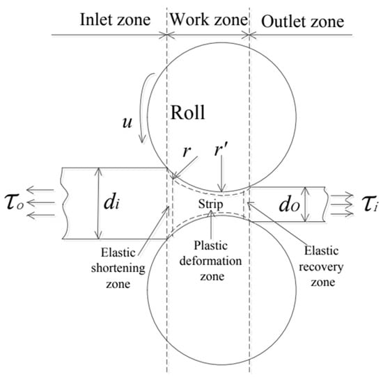
Figure 1.
Geometric model of the working interface in the rolling process.
represents the inlet thickness of the deformation area of the rolled piece, (unit: mm); represents the outlet thickness of the deformation zone of the rolled piece, (unit: mm); represents the tension before rolling parts, (unit: MPa); represents the tension after rolling, (unit: MPa); represents roll radius, (unit: mm); represents the roll flattening radius, (unit: mm); represents the linear speed of roll surface, (unit: m/s).
According to the metal rolling theory, the relative reduction rate ε is determined by the following equation:
The following equation determines the stress state coefficient Qp model:
where represents the friction coefficient between rolls. The friction coefficient is a non-constant term, due to the fact that the actual working interface is in a state of unsteady lubrication friction, which can be approximated by the Roberts formula [19], and can be determined via the following equation:
where is the unsteady friction coefficient; is the amount of decision pressing; and represent the coefficient of friction characteristics. They can be named according to the actual situation for a reasonable calculation value. The following equation can determine the tension influence coefficient model:
where represents the weighting coefficient of front strip tension, specified as = 0.6; represents the average deformation resistance, (unit: MPa).
3.2. Rolling Force Model
The cold rolling process includes the inlet, working, and exit zones. The working zone is the deformation area of the rolled piece. The deformation zone consists of three elastic zones: the outlet elastic zone, the inlet elastic zone, and the plastic-elastic zone. There is a strong load phenomenon at the working boundary between the roll and the strip, which results in a certain elastic deformation of the roll at the local position. Therefore, the roll-flattening radius must be considered when analyzing the rolling force model [19]. The Bland-Ford model theory is used to develop the rolling force model of cold rolling, which considers plastic deformation, elastic deformation, and unstable disturbance of the roll-flattening radius.
The total rolling force, , is determined by the following equation:
where is the rolling force in the plastic-deformation zone, is the rolling force in the elastic-deformation zone; the rolling force in the plastic-deformation zone is determined by the following equation:
where represents the width of rolled pieces (unit: mm); indicates the contact arc length of the roll after flattening (unit: mm).
It is clear from the formula that the roll flattening radius affects the range of the rolling force in the plastic deformation zone; thus, a mathematical model of the roll-flattening radius must be developed. According to the elastic contact deformation theory, the contact arc length is determined by the following equation:
where represents the absolute amount of pressure (unit: mm).
According to Hitchock formula, the roll-flattening radius is as follows:
where represents the Poisson’s ratio of the roll; represents the elastic modulus of the roll; represents the effective pressure reduction volume (unit: mm); according to the elastic-deformation theory, it can be defined as the following equation:
Among:
where represents the pressure reduction in the elastic-recovery area (unit: mm); represents the amount of compression in the elastic-compression zone (unit: mm); represents the amount of compression in the plastic-deformation zone (unit: mm); represents outlet-deformation resistance (unit: MPa); for reasonable calculation, is usually defined as the Hitchock formula constant of the calculation model, which can be valued according to the actual situation.
The rolling force is determined by the following equation:
where represents the rolling force in the elastic zone (unit: kN); represents the rolling force in the elastic-recovery zone (unit: kN).
3.3. Decoupling of Roll-Flattening Radius and Rolling Force Model
Based on the rolling force model and the roll-flattening radius calculation model, a coupling relationship between them can be observed. Although the results are typically obtained through simultaneous iterative calculations, the editing of the calculation program tends to be complex, and non-convergence may occur. Therefore, decoupling the two models can yield an explicit formula for the rolling force model.
Equations (12) and (6) are substituted into Equation (5) and converted into the form of a roll-flattening radius, and replaced by the following equation:
where represent parameters independent of the roll-flattening radius, and the rolling force model is determined by the following equation:
The roll flattening radius of Equation (8) is sorted out in a parametric way:
It can be known that b1 and b2 are parameters independent of the rolling force, and the roll-flattening radius is determined by the following equation:
Through transformation Equation (14), obtain
Substituting Equation (15) into Equation (13), a quadratic equation with one variable about can be obtained as follows:
If , the equation has a positive solution, and the following equation determines the roll-flattening radius after decoupling:
In conclusion, the rolling force can be separated via plugging Equation (16) into Equation (13), and you can obtain the rolling force display formula shown below:
4. Numerical Analysis of the Rolling Force Model
The accuracy of the newly developed rolling force model can be verified by conducting numerical simulations and field tests. The numerical calculation accuracy can be determined based on comparing the model predictions and the actual results. For instance, a field test was conducted on producing thin strip steel in a large cold rolling enterprise, as depicted in Figure 2. The industrial parameters related to material processing, such as strip width, inlet and outlet thickness, front and rear tension, reduction amount, and velocity, are provided in Table 1 and Table 2.
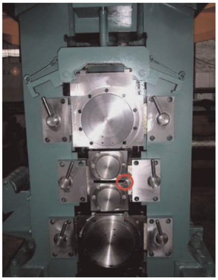
Figure 2.
Field test.

Table 1.
Data information of the steel coil.
Table 2.
Comparison of the rolling production site data of each rolling pass.
The simulation test is conducted using the data presented in Table 1 and Table 2. By utilizing the numerical calculation process depicted in Figure 3, the results obtained from the new rolling force model are compared with the calculation results of the original rolling force model. In the rolling force measurement, due to the influence of various factors, to characterize the rationality of the measurement results, uncertainty factors such as instrument resolution, environmental conditions, and measurement methods are considered [21], and the data statistics are shown in Table 3. The comparison data, as shown in Table 4, are sorted out for analysis.
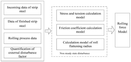
Figure 3.
Numerical calculation process.
Table 3.
Uncertainty of the measurement data.
Table 4.
Numerical calculation results of each rolling pass.
The numerical results indicate that the rolling force model proposed in this paper exhibits good consistency with the actual measurements, with an error range of approximately 8%. Compared to the original numerical calculation model that only considers elastic-plastic deformation, the proposed model aligns more closely with the actual rolling force observed in industrial production. These findings provide evidence of the established model’s high prediction accuracy and ability to represent the cold rolling forming process accurately.
The intermediate pass plays a crucial role in the stability of cold tandem rolling [22]. In this study, the focus is on intermediate passes. The relationship between the friction coefficient and the rolling force is depicted in Figure 4. It can be observed that the rolling force increases with an increase in the friction coefficient. However, beyond a friction coefficient of 0.2, the rate of increase in rolling force tends to decrease. While a smaller friction coefficient leads to energy savings, it also results in poor rolled surface quality due to the fluid dynamic state at the working interface of the roll and the rolled piece, as well as the lack of constraints on grain deformation on the rolled surface. Therefore, designing lubrication technologies is an effective approach to reducing the rolling force, saving energy, and improving strip production quality.
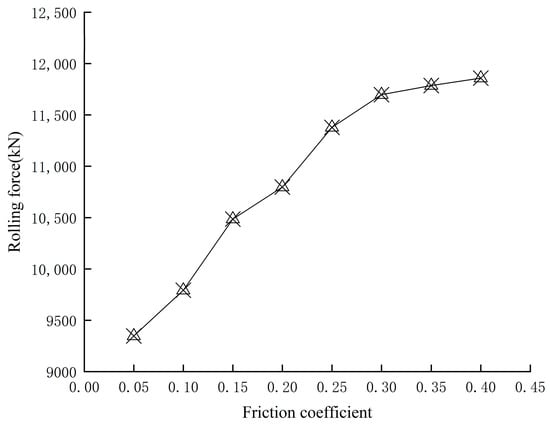
Figure 4.
Relationship between friction coefficient and rolling force.
The relationship between stress and rolling force is depicted in Figure 5. It can be observed that as the stress increases from 50 to 150, the rolling force exhibits a linear growth. Thus, to enhance the stability of the rolling force, it is advisable to utilize high-quality strip and blank materials.
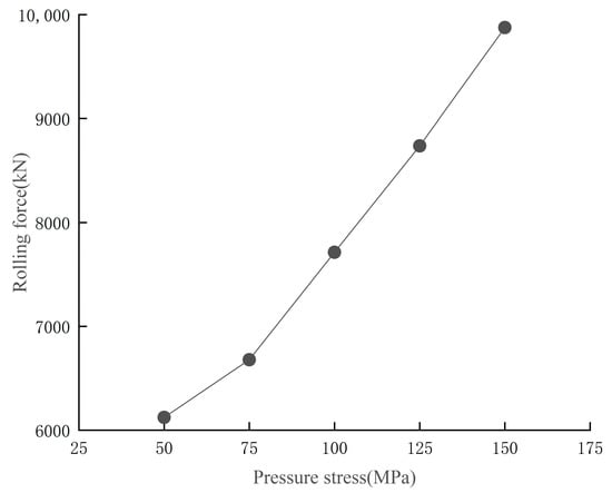
Figure 5.
Relationship between pressure stress and rolling force.
The relationship between tension and rolling force is depicted in Figure 6, which shows that as the front and rear tension increases, the rolling force decreases. This can be attributed to the reduction of three-way compressive stress in the plastic deformation zone of the strip due to the increase in tension. Consequently, there is a transformation of compressive stress into tensile stress. As a result, the rolling force decreases, and the thickness of the rolled piece becomes thinner than the standard. Therefore, effective control of the tension between stands can enhance rolling stability.
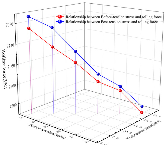
Figure 6.
Relationship between tension stress and rolling force.
By iteratively applying the rolling force calculation formula and the roll flattening radius calculation formula to decouple them, as depicted in Figure 7, the rolling force values gradually stabilize and converge after four iterations. To investigate the impact of the roll flattening radius on the rolling force, data from the five passes mentioned above are selected for analysis. The comparison between the rolling force calculation results obtained without considering the roll flattening radius and those obtained by considering the roll flattening radius is depicted in Figure 8. The calculated results obtained without considering the roll-flattening radius deviate significantly from the measured values of the rolling force. This observation emphasizes the crucial role of the roll-flattening radius in determining the accuracy of the rolling force calculation.
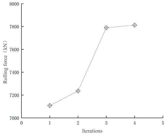
Figure 7.
Variation rolling force with the iteration process.
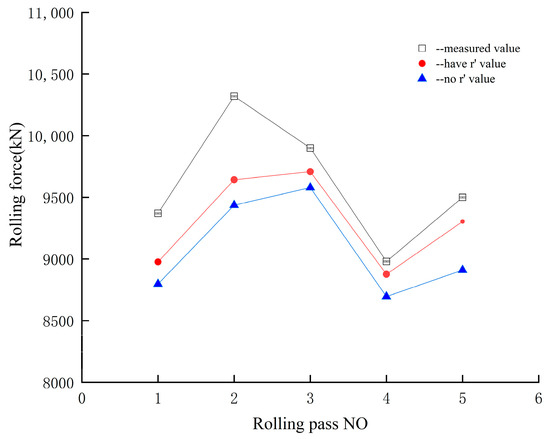
Figure 8.
The numerical comparison.
5. Conclusions
In the this work, the study initially focused on important factors such as lubrication, friction, stress, tension, and roll-flattening radius in the rolling process. Mathematical models were separately established for the friction coefficient and roll-flattening radius. Subsequently, the mathematical models for the non-steady-state friction coefficient and roll-flattening radius were decoupled from the Bland-Ford-Hill rolling-force-calculation formula, proposing a novel rolling force model that considers the coupling of multiple parameters in the cold rolling process. Next, production data of thin strip steel from a large-scale company were utilized to analyze the effects of the friction coefficient, stress, tension before and after rolling, and roll-flattening radius on the rolling force. The following conclusions were drawn from the study: (1) The rolling force increases with an increase in the friction coefficient. When the friction coefficient exceeds a certain value, the rate of increase in the rolling force decreases. As the friction coefficient increases, the fluid lubrication decreases, approximating a dry friction state. However, an excessively low friction coefficient can also impact the rolling quality. (2) The rolling force exhibits a linear increase with increasing stress. Maintaining a constant stress level in high-quality rolled products helps ensure the stability of the rolling force. (3) The rolling force decreases with increasing tension before and after rolling. Effective control of the inter-stand tension enhances the rolling stability. (4) By comparing the actual measured rolling forces at each pass of the cold rolling process with the calculated values from the newly developed rolling force model and the rolling force model that does not consider the roll-flattening radius, it was found that the calculated values from the new model closely approximate the measured values. This indicates that an accurate prediction of the roll-flattening radius can improve the precision of rolling force calculations.
This research establishes a robust foundation for simulating rolling forces in the cold rolling process and provides valuable guidance for controlling rolling forces in practical production. However, cold rolling is an exceedingly complex process, and future research should also consider the influence of rolling interface roll vibrations and bending forces on the rolling force.
Author Contributions
Conceptualization, L.T.; data curation, H.W.; methodology, Q.W.; validation, H.W.; writing—original draft, L.T.; writing—review and editing, Q.W. All authors have read and agreed to the published version of the manuscript.
Funding
The work was supported by National Natural Science Foundation of China (Project No. 51875146) and the Natural Science Foundation of Zhejiang Province, China (Project No. LY21E050005).
Institutional Review Board Statement
Not applicable.
Informed Consent Statement
Not applicable.
Data Availability Statement
Not applicable.
Acknowledgments
This work is supported by the Zhejiang Provincial Key Laboratory of Special Processing, Hangzhou Dianzi University.
Conflicts of Interest
The authors declare no conflict of interest.
References
- Liu, Y.M.; Wang, Z.H.; Wang, T. Prediction and Analysis of the Force and Shape Parameters in Variable Gauge Rolling. Chin. J. Mech. Eng. 2022, 35, 88. [Google Scholar] [CrossRef]
- Wei, L.X.; Zhai, B.H.; Sun, H. An ensemble JITL method based on multi-weighted similarity measures for cold rolling force prediction. ISA Trans. 2022, 126, 326–337. [Google Scholar] [CrossRef] [PubMed]
- Liu, S.; Lu, H.F.; Zhao, D.X. Dynamic rolling force modeling of cold rolling strip based on mixed lubrication friction. Int. J. Adv. Manuf. Technol. 2020, 108, 369–380. [Google Scholar] [CrossRef]
- Wang, Q.Y.; Zhang, Z.; Chen, H.Q. Characteristics of unsteady lubrication film in metal-forming process with dynamic roll gap. J. Cent. South Univ. 2014, 21, 3787–3792. [Google Scholar] [CrossRef]
- Cao, L.; Li, X.; Wang, Q.L. Vibration analysis and numerical simulation of rolling interface during cold rolling with unsteady lubrication. Tribol. Int. 2021, 153, 106604. [Google Scholar] [CrossRef]
- Wu, C.; Zhang, L.; Li, S. A novel multi-scale statistical characterization of interface pressure and friction in metal strip rolling. Int. J. Mech. Sci. 2014, 89, 391–402. [Google Scholar] [CrossRef]
- Kosasih, P.B.; Tieu, A.K. Mixed film lubrication of strip rolling using O/W emulsions. Tribol. Int. 2007, 40, 709–716. [Google Scholar] [CrossRef]
- Maksimov, E.A. Reducing pressure on the rolls and tension in the asymmetric cold-rolling of strip. Metallurgist 2010, 54, 11–12. [Google Scholar] [CrossRef]
- Zhao, Q.L.; Liu, X.H.; Sun, X.K. Analysis of Mechanical Parameters of Asymmetrical Rolling Dealing with Three Region Percentages in Deformation Zones. Materials 2022, 15, 12–19. [Google Scholar] [CrossRef]
- Liu, X.H.; Xu, S.; Li, S.Q. FEM Analysis of Rolling Pressure Along Strip Width in Cold Rolling Process. J. Iron Steel Res. Int. 2007, 14, 22–26. [Google Scholar] [CrossRef]
- Zhu, G.M.; Du, F.S.; Sun, D.Y. FEM Revise of Hitchcock Equation of Calculating Working Roll′s Contact Flattening in Cold Strip Steel Rolling. Chin. J. Mech. Eng. 2003, 39, 135–137. [Google Scholar] [CrossRef]
- Sun, D.Y.; Du, F.S.; Zhu, G.M. Accurate and Fast Simulation of Rolling Force Model in Cold Strip Rolling. Iron Steel 2003, 38, 32–35. [Google Scholar]
- Le, H.R.; Sutcliffe, M.P.F. A Robust Model for Rolling of Thin Strip and Foil. Int. J. Mech. Sci. 1995, 53, 846–856. [Google Scholar] [CrossRef]
- Gao, Z.Q.; Fu, W.P.; Wang, W.; Wang, S.Q. The Modeling for the Normal Contact Stiffness and Damping of Anisotropic Interface. Mech. Solids 2021, 56, 534–550. [Google Scholar] [CrossRef]
- Yuen, W.Y.D.; Dixon, A.; Nguyen, D.N. The Modelling of the Mechanics of Deformation in Flat Rolling. J. Mater. Process. Technol. 1996, 60, 87–94. [Google Scholar] [CrossRef]
- Li, L.J.; Xie, H.B.; Liu, T.W. Effects of Rolling Force on Strip Shape during Tandem Cold Rolling Using a Novel Multistand Finite Element Model. Steel Res. Int. 2022, 93, 2100359. [Google Scholar] [CrossRef]
- Li, L.J.; Xie, H.B.; Pan, D. Influence of intermediate roll shifting on strip shape in a CVC-6 tandem cold mill based on a 3D multi-stand FE model. Int. J. Adv. Manuf. Technol. 2022, 121, 4367–4385. [Google Scholar] [CrossRef]
- Stratmann, A.; Jacobs, G.; Hsu, C.J. Antiwear tribofilm growth in rolling bearings under boundary lubrication conditions. Tribol. Int. 2017, 113, 43–49. [Google Scholar] [CrossRef]
- Heidari, A.; Forouzan, M.R.; Akbarzadeh, S. Development of a Rolling Chatter Model Considering Unsteady Lubrication. Trans. Iron Steel Inst. Jpn. 2014, 54, 165–170. [Google Scholar] [CrossRef]
- Lorentz, B.; Albers, A. A numerical model for mixed lubrication taking into account surface topography, tangential adhesion effects and plastic deformations. Tribol. Int. 2013, 59, 259–266. [Google Scholar] [CrossRef]
- Zhang, S.H.; Deng, L.; Che, L.Z. An integrated model of rolling force for extra-thick plate by combining theoretical model and neural network model. J. Manuf. Process. 2022, 75, 100–109. [Google Scholar] [CrossRef]
- Wang, Q.Y.; Cui, M.C.; Wang, H. Establishment and simulation analysis of coupled vibration system model between stands of tandem rolling mills based on rollers multi-modal mode. J. Cent. South Univ. 2020, 51, 2834–2843. [Google Scholar] [CrossRef]


Disclaimer/Publisher’s Note: The statements, opinions and data contained in all publications are solely those of the individual author(s) and contributor(s) and not of MDPI and/or the editor(s). MDPI and/or the editor(s) disclaim responsibility for any injury to people or property resulting from any ideas, methods, instructions or products referred to in the content. |
© 2023 by the authors. Licensee MDPI, Basel, Switzerland. This article is an open access article distributed under the terms and conditions of the Creative Commons Attribution (CC BY) license (https://creativecommons.org/licenses/by/4.0/).