1. Introduction
High-speed permanent magnet motors have a promising future. It is small, has a high power density, and can be directly connected to high-speed loads [
1,
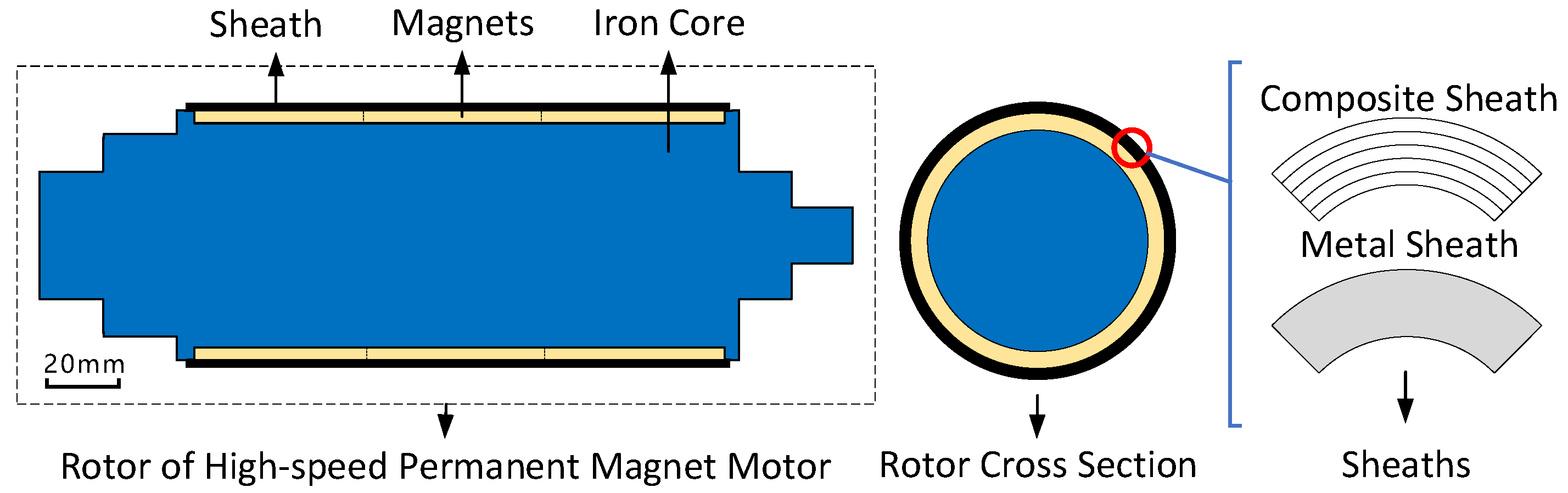
2]. The rotor structure is shown in
Figure 1, and the mechanical strength of the magnets is poor, so additional sleeve protection is required. Two kinds of sleeves are commonly used, namely metal sleeves and composite sleeves. Among them, carbon fiber composite protective sleeves have the following advantages: they have weak conductivity, which reduces eddy current losses in the sleeve [
3]; they also have low density, which increases motor power density; additionally, they have higher strength and require less thickness than other materials, maximizing the actual air gap of the motor and creating possibilities for electromagnetic coil design [
4].
There are many scholars who have studied the composite sleeving of high-speed permanent magnet motors. For example, articles [
5,
6,
7,
8] analyzed the stress and deformation of the sleeve under different operating conditions by analytical calculations and finite element methods. They calculated the preload or interference required for safe rotor operation of the sleeve. This ensures that both the structural strength of the rotor and the electromagnetic performance of the sleeve meet usage requirements. Although they designed the sleeve better, they ignored the effect of the sleeve preparation process on its performance. In fact, winding tension, winding angle, curing method, and choice of carbon fiber and resin in the preparation process all impact the performance of carbon fiber composite sleeves. Selecting a suitable sleeve preparation process to reduce sleeve thickness and improve sleeve performance is a key issue that needs urgent study. Therefore, this paper analyzes the carbon fiber composite sleeve preparation process parameters for high-speed permanent magnet motors one by one and summarizes suitable process parameters for practical use.
Reference [
9] analyzed different sleeve materials and thicknesses for the rotor of a 350 kW, 20,000 rpm motor and found that a thinner carbon fiber sleeve can reduce the electromagnetic loss of the motor. Reference [
10] analyzed the multi-layer and multi-angle winding of carbon fiber sleeves for an 80 kW, 60,000 rpm motor. Reference [
11] established a deformation and stress model for a multi-angle winding hybrid composite cylinder under axial load and internal and external pressure. Reference [
12] studied the effect of composite winding angle and layer number on the bursting strength of pressure vessels using finite element models. Reference [
13] studied the effect of composite fibers, matrix volume fraction, and winding angle variation on the compressive performance and axial bearing capacity of flat tubes. These studies focused on multi-layer and multi-angle winding analysis, finite element models, etc., but lacked experimental verification. Therefore, further experiments are needed to verify these theoretical results.
The references for the winding process and testing are included in
Table 1.
References [
14,
15] studied the effect of winding angle on the failure mode of carbon fiber composite materials. It was found that the compressive strength of composite materials decreases with increasing winding angle, and the failure modes are brittle fracture, local buckling, and transverse shear. References [
14,
15] prepared a protective sleeve in three layers according to winding angles of 90, 55, and 90°, gradually increasing the thickness of the middle layer. Pipes with a diameter-to-thickness ratio of less than 20:1 fail by buckling, while those with a ratio greater than 20:1 fail by shearing. Reference [
16] explored the relationship between winding angle and failure mechanisms of composite materials mixed with an aluminum layer protective sleeve. With the increase in the winding angle, the compressive strength of the protective sleeve decreases, leading to a change in the failure mode from fracture to local buckling.
Reference [
17] used NOL ring failure experiments to find that in the dry winding process, the strength of the protective sleeve first increases and then decreases with an increase in winding tension. The curing process leads to a decrease in the pretension of fibers inside the protective sleeve. Reference [
18] studied the effect of different pre-tension forces and winding drum diameters on strength loss during fiber winding through experiments. It was found that both affect fiber strength by changing the frictional force between fibers and equipment. However, this study was designed with a small winding tension.
In addition, it has been found that the tension in fibers exerts a radial pressure on the inner composite, causing a relaxation of the tension in the fibers first wound on the core mold [
19]. To solve this problem, some scholars have proposed reducing the remaining winding tension gradient of the composite by using a layered curing process [
20].
Many scholars have studied the curing method of composite materials. For example, References [
21,
22] studied the relationship between the curing method and the quality of composite materials. They found that increasing the curing pressure and temperature changed the viscosity and fluidity of the resin. High-toughness composites are easy to produce with curing defects under vacuum conditions. Reference [
23] investigated the effect of stage curing on composite materials and found that stage curing is beneficial for reducing porosity content and improving product quality.
Analyzing existing data, it was found that there are few studies directly on the composite sleeve technology for high-speed permanent magnet motors. Existing research mainly focuses on the theoretical design of sleeves and the molding process of composite materials, with the latter usually focusing on pressure vessels. Therefore, this paper proposes to study the relationship between the performance of composite sleeves for high-speed permanent magnet motors and the selection of resins, fibers, and winding process from the perspective of motor requirements. In this paper, we used the Taguchi method [
24] for research, and selected different carbon fibers, resins, winding angles, winding tensions, and curing rates and times to prepare NOL rings. The NOL test, which can measure the macroscopic mechanical properties of ring composites and characterize the interfacial bonding properties of composites, was used as an analytical tool. The properties of the composites made by wet winding and dry winding were investigated by tensile shear testing and resin content testing, respectively. The macroscopic mechanical properties of the resin and carbon fiber were evaluated, and the influence of the process on the composite properties was studied. The sleeve selection and winding method with good mechanical properties were obtained, and a composite sleeve with easy winding for motors was obtained. This paper provides a systematic solution for the selection and process design of rotor sleeves for high-speed permanent magnet motors. The winding process flow of the high-speed permanent magnet motor rotor composite sleeve is shown in
Figure 2.
2. Test Content and Methods
The NOL ring damage tests use T700 grade carbon fiber and epoxy resin as composite material systems. The tests mainly include three parts:
The effect of three factors (winding angle (A), fiber type (B), and resin type (C)) on the damage strength of the composite at different levels;
The effect of carbon fiber winding tension on the mechanical properties and resin content of the composite;
The effect of layered curing during dry winding and the rate of temperature rise during curing on the quality and properties of the composite.
Three types of fiber bundles were used in the wet winding tests: T-700 12k from Toray Co., Ltd., Tokyo, Japan; SYT49s 12k from Zhongfu Shenying Carbon Fiber Co., Ltd., Jiangsu, China; and TZT700s 12k from Weihai Guangwei composite material Co., Ltd, Shandong, China. Their thicknesses were 0.125 mm and their widths were 4 mm. The resin adopts three resins with different heat resistance grades provided by Harbin FRP Institute Co., Ltd., Harbin, China: HBY-SL-03-01, HBY-SL-03-02, and HBY-SL-03-03. The viscosity of the first two resins is 700 mPas, and the viscosity of the last one is 500 mPas. The resin curing systems are as follows:
HBY-SL-03-01:80 °C/4 h + 140 °C/2 h + 200 °C/4 h.
HBY-SL-03-02:90 °C/2 h + 140 °C/2 h.
HBY-SL-03-03:100 °C/1 h + 120 °C/1 h + 180 °C/2 h.
The dry winding test material is epoxy-slit narrow tape with EM817 resin. The fibers chosen are 12KHF40T-U-125GSM produced by Jiangsu Hengshen Co, Jiangsu, China. The filament width is 6.35 mm, the thickness is 0.125 mm, and the resin content is 33%. The curing system is as follows: 80 °C/2 h + 100 °C/2 h + 125 °C/3 h. The winding tension is 700 N.
2.1. Experimental Design
The Taguchi method is a commonly used experimental optimization technique that can achieve more accurate and reliable results with fewer experiments [
23]. Generally speaking, it involves multiple factors at multiple levels, requiring orthogonal experimental design, and then determining the optimal parameter combination by analyzing the experimental results.
In the case of the NOL ring preparation process, experiments were designed according to the Taguchi method to study the effects of winding angle, fiber type, and resin type on the sleeve’s performance. Three levels were selected for each factor in the experiment, totaling nine groups of experiments. By analyzing these nine groups of experiments, comprehensive experiments were obtained with 27 combinations of results.
The experimental table is shown in
Table 2, where the winding angle of 45° refers to the inner layer ring winding 0° in the circumferential direction, the middle layer helix winding 45°, and the outer layer ring winding 0°, and the three layers have the same thickness. The winding angle of 30° refers to the inner layer ring winding 0° in the circumferential direction, the middle layer helix winding 30°, and the outer layer ring winding 0°, and the three layers have the same thickness. The winding angle of 0° represents only circumferential winding. The experiment used a commonly used tension of 60 N for wet winding. The NOL ring formed by winding had the following geometric dimensions: 13.97 mm in width, 1.38 mm in thickness, and an inner diameter of 84.00 mm.
To investigate the maximum winding tension of wet winding, an experimental design was conducted. The winding angle of NOL rings was selected as circumferential, and the resin was selected as HBY-SL-03-01. The winding tension was gradually increased from 70 N to 130 N, in increments of 10 N.
As the tension of wet winding gradually increases to 130 N, the performance of composite materials begins to decline. Therefore, subsequent research on dry winding curing was carried out to provide greater pressure for motor protection. As the sleeve winding process proceeds, the outer fibers of the composite relax the inner fibers. To suppress this effect, a layered curing method can be adopted. For the two variables in the layered curing, the number of cures and the rate at which the temperature rises during the curing process, the experiments are designed as shown in
Table 3.
2.2. NOL Ring Preparation and Performance Test Methods
NOL ring tensile and shear tests adopt the national standard of the People’s Republic of China, “Mechanical Properties Test Method for Filament Winding Reinforced Plastic Ring Specimens,” code name GB/T1458-2008 [
25].
To prepare tensile-shear specimens, the following steps were taken: firstly, a release agent was applied to the winding mold, and the pipe was wrapped to its full length and full wall thickness; then, it was cured in the curing furnace and demolded; finally, the wet-wound pipe was cut according to size, manually polished, and numbered. Because there is a large dispersion in the preparation process of NOL ring winding, nine horizontal tests were selected for tensile and shear tests. Twenty-one groups of tests mentioned in the article required a total of 252 NOL rings to prepare tensile-shear specimens. Tensile tests were performed on a universal testing machine at a loading speed of 2 mm/min, while shear tests were performed at a loading speed of 1 mm/min. The test temperature was 23 °C and the humidity was 55%. The tensile-shear test is shown in
Figure 3.
The tensile strength of NOL rings was calculated according to the following formula [
25]:
where
is the tensile strength of NOL rings, in MPa;
is the failure load, in N;
L is the width of the sample, in mm; and
h is the thickness of the sample, in mm.
The shear strength of NOL rings was calculated according to the following formula [
25]:
where
is interlaminar shear strength, in MPa;
is the failure load, in N;
L is the width of the sample, in mm; and
h is the thickness of the sample, in mm.
Discretization was calculated according to the following formula [
25]:
where
is the discrete value of nine groups of data at each level,
is the variance of nine groups of data at each level, and
is the mean value of nine groups of data at each level.
3. Results and Discussion
The tensile strength and interlaminar shear strength of the sample at each level were calculated, respectively, according to Equations (1) and (2). The average value of the calculated results of multiple groups at each level was obtained, and the dispersion coefficient was calculated according to Equation (3). The obtained data are plotted in
Table 4 and
Table 5. Among them, KA1~KC3 correspond to the mean value of data at level 1 of factor A to the mean value of data at level 3 of factor C.
3.1. Effect of Winding Angle
The tensile failure results of NOL rings with different winding angles are plotted in
Figure 4. The relationship between tensile strength and shear strength is as follows:
where
is the failure strength when the winding angle is 45°,
is the failure strength when the winding angle is 30°, and
is the failure strength when the winding angle is 0°.
The maximum tensile strength appears at the 0° circumferential winding level, and its size is 2474 MPa. The tensile failure values of NOL rings with winding angles of 45 and 30° are 1853 and 1957 MPa, respectively. This is determined by the anisotropy of carbon fiber. When winding at 0°, the force stretches along the direction of the fiber, which can give full play to the bearing capacity of the fiber. The sleeve has good radial and circumferential mechanical properties.
The volume content of NOL ring fibers with a winding angle of 0 ° was calculated according to Formulas (5) and (6) [
26]. The NOL ring resin mass content is known to be 19.89%.
where
and
are fiber mass and resin mass, respectively, and
and
are fiber density and resin density, respectively.
,
.
The fiber tensile strength after winding is calculated as follows:
where
is the tensile strength of fiber after winding and
is the tensile failure strength of NOL.
The tensile strength of a single bundle of T700-grade carbon fibers is 4900 MPa. Ignoring the contribution of resin strength to the strength of the composite, the tensile strength of a purely circumferentially wound NOL ring is reduced by 30% during the process compared with a single bundle of fibers.
By calculation, the tensile strength of NOL rings with 45 and 30° winding angles is reduced by 20~25% compared with that of rings with pure circular winding. Theoretically, the tangential stress equivalent values of NOL rings with 45 and 30° winding angles are 90 and 95.5% of pure annular winding, respectively, but the measured values are smaller than the equivalent values. This is because, in the process of preparing NOL ring samples, the fibers in the spiral direction will be cut off, the tension exerted on the fibers will be relaxed, and the fibers will shrink in the composite material. The interfacial integrity between the fibers and the matrix is disrupted. It affects the uniformity of force transfer between the spiral wound layer fibers and the substrate, the interlayer bonding, and the overall mechanical properties of the material. The mechanical properties of 45°-wound NOL rings and 30°-wound NOL rings are reduced by 17.76 and 16.24%, respectively. A similar law can be obtained from the interlaminar shear strength.
3.2. Effect of Fiber Types
Comparing the tensile failure results of NOL rings with different fiber types, it is found that SYT49s-12k fiber possesses the maximum failure strength, and the difference in failure strength of different fibers is not obvious. Therefore, separate experiments were designed for different fiber types. The influence of different kinds of fibers on the mechanical properties of composite materials was studied by keeping the type of resin unchanged and setting the winding angle at 0°.
It can be seen from
Figure 5 that TZT700s-12k fiber has poor performance and T-700-12k fiber is in the middle when HBY-SL-03-03 resin is used for circumferential wounding at room temperature. SYT49s-12k fiber has the best mechanical performance, and its tensile strength is 32.3% higher than TZT700s-12k fiber.
As can be seen from
Figure 6, when HBY-SL-03-01 resin is used for circumferential winding at room temperature, the mechanical properties of TZT700s-12k and T-700-12k fibers are still inferior to those of SYT49s-12k fibers. Therefore, under the current test conditions, the mechanical properties of SYT49s-12k are the best.
3.3. Effect of Resin Types
The NOL ring failure data of different resin types were sorted in
Figure 7. From the tensile strengths and interlaminar shear strengths of the three levels, it is known that the breaking strengths of NOL rings prepared with HBY-SL-03-01 resin and HBY-SL-03-02 resin are higher than those of NOL rings prepared with HBY-SL-03-03 resin. It was found that the viscosity of HBY-SL-03-01 and HBY-SL-03-02 resins was the same, both higher than that of HBY-SL-03-03 resin. It is known that resin viscosity is one of the factors affecting the mechanical properties of NOL rings. The resin with higher viscosity is easier to wrap on the surface of carbon fiber, which can more effectively protect the carbon fiber during the process, reduce fiber wear, and improve the quality of the composite. In addition, as the viscosity of the resin increases, the crosslink density between the resin molecules increases, which also leads to a decrease in the tensile strength of the composite [
27].
3.4. Effect of Wet WindingTension
For wet winding, failure data of NOL rings with different winding tensions are sorted in
Figure 8. When the winding tension varies between 70 and 130 N, the failure load of composite materials decreases as the winding tension increases. The NOL ring with a winding tension of 70 N has the highest tensile strength and shear strength, which are 2453 and 43 MPa, respectively, and the NOL ring with a winding tension of 130 N has the lowest tensile strength and shear strength, which are 2143 and 38 MPa, respectively.
Figure 9 shows the relationship between winding tension and resin content in NOL ring samples. It can be seen that the resin content decreases with increasing winding tension. The content of NOL ring resin is the highest (21.3%) when the tension is 70 N and the lowest (18.9%) when the tension is 130 N.
During the preparation of NOL rings, carbon fibers are combined with resin by siphoning, and the amount of resin bound in this way is limited by the type and cross-sectional area of the fiber tows. After the fiber bundles are fully impregnated with resin, the excess resin will be stored between the fiber bundles due to the wet winding process. This part of the resin is weakly bound to the fiber tows, and the resin will be extruded under the winding tension, and the resin content of the composite decreases. As the fiber winding tension increases, the effect of the unit winding tension on the decrease in resin content is weakened. This is because the distance between fiber bundles decreases as the resin content decreases, the pressure required for the macroscopic flow of resin increases, and the increase in winding tension gradually decreases the increase in resin flow. Although the increase in winding tension decreases the resin content, the process damage to the fibers also increases, so the strength of the composite decreases at higher winding tensions due to process limitations.
Resin content was converted to fiber volume content, and empirical formulas exist for fiber volume content and winding tension.
where
and
are the current fiber volume content and current winding tension, respectively,
and
are the initial fiber volume content and initial winding tension, respectively,
is the ultimate fiber volume content, and
k is the correction factor.
Figure 10 shows the microstructure of composite materials and the schematic diagram of resin-rich regions arranged in hexagons. It is shown that the volume content of the ultimate fibers inside the composite can reach 90.7%. However, it is impossible for carbon fibers to reach the ideal arrangement limit in the resin matrix in engineering, and there must be resin-rich areas in the composite materials. Generally, the fiber volume content ranges from 60 to 80%. Therefore, 0.8 is taken as the ultimate fiber volume content in this paper, and
k is taken as −0.25 after correction with the actual measurement results. The comparison in
Figure 8 shows that the predicted fiber volume content of composite materials is in good agreement with the actual measured results.
3.5. The Effect of the Dry Winding Curing Method
To ensure good interlayer interface performance, the surface of the cured fiber needs to be polished before winding, which will damage the integrity of the surface fiber of the composite material. When the thickness of the composite material is small, the relative damage ratio of the fiber is large. Although lamination curing can inhibit the fluidity of the resin, excessive lamination is not conducive to improving the quality of the sleeve.
Table 6 shows the relationship between curing times of dry winding, heating rate, and failure strength of NOL ring samples. According to the data in the table, the NOL ring prepared by curing twice has the highest tensile strength (1867 MPa), while the NOL ring prepared by curing three times has the lowest tensile strength (1698 MPa).
The maximum tensile strength of NOL rings was 1766 MPa at a heating rate of 1 min/°C, and the minimum tensile strength of NOL rings was 1491 MPa at a heating rate of 3 min/°C. The tensile strength of composites shows a downward trend as the heating rate slows down. This is because the slower the heating rate is, the longer the transition time of resin from its viscous flow state to its glass state will be, and the fluidity of resin will increase, resulting in an uneven distribution of resin inside the composites. The contact time between the composite resin and the external environment increases, which reduces the stability of the curing and heating processes [
28].
3.6. Effect of Interface Performance
The interface of the composite material exists between the region where the properties of the reinforcing agent change and the region where the resin base body is consistent. Its state and strength have a very important effect on the properties of the composite material. Due to the small proportion of the interface relative to the whole composite material, it is difficult to measure separately. In this paper, the NOL ring test was used for macroscopic characterization, and the interface properties were studied by analyzing the fracture morphology of NOL ring samples. As can be seen in
Figure 11, the annularly wound NOL ring is torn, the fibers at the fracture have explosive damage characteristics, and there is obvious delamination in the fracture area. This indicates that the microcrack extends along the fiber interface direction and the composite cracks along the winding direction. NOL interlayer shear ring cracks have no obvious interfacial debonding, fiber pulling out, or brittle fracture. In conclusion, the resin content is appropriate, and the interfacial properties are good during the torus winding. The fracture energy of the composite material is large, and it has certain toughness. After the fracture of the 45° wound NOL ring sample, the fiber crack has a zigzag path and expands in other directions, and the fiber tear failure decreases while the brittle fracture increases. Therefore, it can be inferred that the 45° wound NOL ring sample has a local brittle fracture. The bond strength of the composite material is low, and energy dissipation occurs at the bond. Debonding occurs, forming layered damage. The resin matrix is damaged by shear stress, the material shows irregular damage, and the distribution of broken fibers will be randomly distributed [
29]. In addition, fiber fracture will occur during the processing of the 45° wound NOL ring sample prepared by the ring cutting method, resulting in weak local links. Therefore, the composite property of the 45° wound NOL ring sample is weaker than that of the circumferentially wound sample.


