Abstract
The tightening standards of nitrogen oxides emission from industrial plants encourage nitric acid producers to search for new efficient solutions to meet the stringent emission limits. Industrial practice and the patent literature show that the effectiveness of deNOx (SCR) and deN2O technology is affected not only by the type and shape of the catalyst, but also by the method of its installation in a heterogenous catalytic reactor. The article presents the background of the problem, related to the emission of nitrogen oxides from nitric acid plants, and describes the technology of the tail gases purified from NOx and N2O. It shows various aspects that should be considered in designing reactors for deNOx and deN2O processes in nitric acid plants. The advantages and disadvantages of different catalytic basket designs, their industrial application and the direction of their design development were also indicated.
1. Introduction
The continuous development of technologies for removing harmful components of industrial off-gasses is a consequence of increasingly stringent emission standards and society’s growing awareness about the need to protect the environment for future generations. The term “hazardous gases” refers to substances harmful to human health, the environment and construction materials. In the case of nitric acid plants, these gases are nitrogen oxides, N2O and NOx (NO, NO2).
Nitrous oxide (N2O) is non-toxic to living organisms, but it is a greenhouse gas with a GWP index (Global Warming Potential) 265–300 times greater than CO2 [1]. Due to the high efficiency in absorbing infrared radiation, reducing its emission, even to a small extent, results in a significant reduction in CO2 equivalent emission. Accumulation of N2O is favoured by its long lifetime in the atmosphere, estimated at 116 years [2]. Nitrous oxide also indirectly contributes to the destruction of the ozone layer in the stratosphere, where it is photolyzed and reacts with oxygen to NOx, which reacts then with O3 [2,3].
In nitric acid plants, nitrous oxide (N2O) is formed as a by-product in the process of ammonia oxidation to NO, carried out in the presence of Pt-Rh-Pd catalytic gauzes package [4]:
2NH3 + 2O2 ® N2O + 3H2O + 736 kJ/mol
Moreover, it can also be formed downstream of the catalytic gauzes package in the reaction of unreacted ammonia with NO (Equation (2)), as well as in the process of selective catalytic reduction of NOx (deNOx), carried out in SCR reactors, installed downstream of the absorption column (Equations (1) and (3)):
2NH3 + 8NO → 5N2O + 3H2O + 945.7 kJ
4NO + 4NH3 + 3O2 → 4N2O + 6H2O + 2403.3 kJ
Nitrous oxide is chemically inert and stable at temperatures <700 °C. Therefore, without using technology for its removal, it does not undergo any changes in the entire technological line of nitric acid production and is emitted into the atmosphere with the tail gases stream at a concentration of 500–2000 ppm (depending on the plant type). The nitrous oxide emission can reach a level of ~5 kg/t HNO3, ~7 kg/t HNO3 and ~12 kg/t HNO3 for low-, medium- and high-pressure plants, respectively [5].
Nitrogen oxides, referred to as NOx, are not classified as greenhouse gases, although they are included in the overall radiation balance [6]. Unlike N2O, they have a significant harmful effect on human health. They cause respiratory and cardiovascular diseases, and sometimes cancer or even death. They also harm the environment, contributing to the formation of acid rain and the destruction of the ozone layer in the stratosphere. In addition, they react with other air pollutants, creating the so-called photochemical smog [7,8].
Nitric oxide (NO) is the main product formed in the process of ammonia oxidation, carried out in the presence of Pt-Rh-Pd catalytic gauzes package [4]:
4NH3 + 5O2 → 4NO + 6H2O + 904 kJ/mol
In the technological line of the plant between the ammonia burner and the absorption column, NO partially oxidizes to NO2:
2NO +O2 ↔ 2NO2
In this area of the plant, the presence of NO and NO2 in the gas stream (so-called nitrous gases) is desirable for the production of nitric acid:
3NO2 + H2O → 2HNO3 + NO
Reaction (6) occurs in the liquid phase on the sieve trays (plates) of the absorption column. Additionally, reaction (5) occurs inside the column between the plates in the gas phase. The efficiency of nitrogen oxides absorption in water is never 100%. Therefore, NO and NO2 are always present in the so-called tail gases stream, leaving the absorption column. In this area of the nitric acid plant, they are treated as pollutants. Their amount depends on the size of the absorption column and the conditions in which the absorption process is carried out, i.e., temperature, pressure and gas flow rate. The content of nitrogen oxides in the tail gases stream is usually 2–3 wt. % in relation to the amount of nitric acid produced. Thus, without the technology of NOx removal, their concentration downstream of the absorption column may reach even 3000 ppm for low-pressure plants [4,9,10,11].
NOx and N2O emissions are regulated by the Directive of the European Parliament on industrial emissions 2010/75/EU. Under the guidelines contained in the Official Journal of the European Union L248/3 [12] and the BAT document (Best Available Techniques Reference Document) [13], the current emission limits are 300 ppm N2O and 90 ppm NOx for the existing nitric acid plants, while 100 ppm N2O and 75 ppm NOx for the new ones [9]. Due to the European Union’s pursuit of a “zero-emission” economy, these limits are expected to be tightened in the future. There are two aspects in favour of reducing N2O emissions: environmental and economic. According to the “European Green Deal” communication presented by the European Commission in 2019, by 2030, CO2 equivalent emissions from industrial plants should be reduced by at least 42% in the so-called non-ETS countries (the current level is 30%) and by at least 52% in the EU-ETS countries (the current level is 43%), in relation to the emissions recorded in 2005. This involves the need to reduce greenhouse gas emissions, even in the plants that have been considered low-emission. The second aspect in favour of lowering N2O emission is related to the possibility of CO2eq emission allowances trading. Currently, the reduction in nitrous oxide emissions to a level lower than that resulting from the established emission standards gives a profit of several dozen EUR/day for each additional 1 ppm of N2O reduced [14,15,16].
Due to the tightening legal requirements regarding N2O and NOx emission standards and the economic aspect, scientists and engineers put much effort into improving the technology for removing these harmful gaseous pollutants from nitric acid plants. Most of the work is focused on developing and testing the catalysts for N2O decomposition/reduction (deN2O) and NOx reduction. Only a few scientific and technical studies concern the design of catalytic baskets or reactors for the deNOx/deN2O processes (Section 2). The industrial experience of Łukasiewicz-INS shows that the design and technical condition of the catalytic basket, supporting a catalyst bed, significantly influences the catalyst efficiency.
The article presents solutions in the field of technology for removing N2O and NOx from the tail gases in nitric acid plants, focusing mainly on the design of the catalytic baskets, installed inside deNOx/deN2O reactors.
2. Technologies for Purifying the Tail Gases from N2O and NOx
According to the BAT guidelines [13], the best available technologies for nitrous oxide emission abatement in nitric acid plants are a high-temperature catalytic N2O decomposition in the nitrous gases stream (HT-deN2O), low-temperature decomposition (LT-deN2O) and catalytic reduction of N2O in the tail gases stream. The first of these processes is carried out in an ammonia oxidation reactor, where achieving a profound reduction in N2O emissions, exceeding 95% of the initial value, is technologically very difficult. A low-temperature N2O decomposition or reduction technology is a more practical and effective solution. The implementation of the N2O removal process at the end of the technological line of nitric acid production (downstream of the absorption column) for a given type of catalyst allows for achieving a nearly 100% reduction in N2O emission, by selecting the appropriate catalyst load, as well as the design of the catalytic basket and deN2O reactor [17].
The process of catalytic N2O reduction is mainly carried out in the presence of zeolites (e.g., ZSM-5, BEA, MFI, FAU or FER) modified with iron or copper ions (in the presence of Fe-FER a simultaneous reduction of NOx and N2O is possible) [18]. Hydrogen, or more often hydrocarbons (e.g., methane, propane), are used as a reducing agent:
CH4 + 4N2O → CO2 + 2H2O + 4N2 (T = 350–450 °C)
N2O reduction with ammonia is also possible in the presence of iron-modified zeolites. However, this process is non-selective in the presence of NOx and requires an operating temperature >440 °C to achieve 95% N2O reduction [17,19,20].
In a low-temperature catalytic N2O decomposition process, catalysts based on transition metals (Cu, Co, Fe, Ni) on various supports, i.e., ZnO, CeO2, Al2O3, TiO2, ZrO2, hydrotalcite, perovskite and zeolite, can be used. Among the transition metal oxides, spinel-based catalysts, e.g., Fe3O4 and Co3O4 are preferred. A particular difficulty in using catalysts based on transition metal oxides may be the inhibitory effect of other tail gases components (i.e., NOx, O2 or H2O) on the deN2O process. Purifying the tail gases at a temperature >350 °C can reduce the adverse effect of the water presence on the activity of these spinels. The problem with NOx influence can be solved by using a reactor with a deNOx/deN2O dual-bed catalytic system, in which the gas stream is first purified of NOx. In the process of low-temperature N2O decomposition, zeolite catalysts modified with copper and iron ions are also used, the most popular of which is Fe-ZSM-5. These catalysts can perform a dual function of catalyzing the N2O decomposition and NOx reduction. A commercial catalyst for N2O decomposition is, for example, Clariant EnviCat® N2O in the form of trillobes, ensuring over 99% efficiency of N2O removal from the tail gases stream [21,22,23,24,25].
One of the best available techniques for reducing NOx emissions from nitric acid plants is the selective catalytic reduction of NOx with ammonia, carried out between the absorption column and the expansion turbine. Such a location enables the deNOx process to be carried out under high pressure, which allows for using a smaller volume of the catalyst bed than installing the reactor downstream of the expansion turbine. In such cases, preheating the tail gases to the operating temperature of the catalyst is often not required. However, in the case of tail gases purifying upstream of the expansion turbine, apart from the operating temperature, selecting a suitable form of the catalyst is also crucial. It should ensure low-pressure drops across the catalyst bed, not causing significant energy losses at the gas inlet of the expansion turbine [13,26,27].
The selective catalytic reduction of NOx with ammonia, depending on the temperature, oxygen content and NO2/NOx molar ratio in the purified tail gases, can proceed according to the following reactions:
4NO + 4NH3 + O2 → 4N2 + 6H2O
NO + NO2 + 2NH3 → 2N2 + 3H2O
2NO2 + 4NH3 + O2 → 3N2 + 6H2O
Under non-optimal process conditions for a given type of catalyst, undesirable side reactions may occur in the reactor, leading to the formation of N2O and NO [28,29,30,31]. The selective catalytic reduction of NOx with ammonia is usually carried out at a temperature higher than 200 °C, due to the risk of ammonium nitrate accumulation in the reactor. The upper limit of the process temperature is determined by the type of catalyst and the maximum operating temperature of the expansion turbine [32]. In the case of oxide catalysts based on transition metals (e.g., V2O5), it should be equal to or lower than 400 °C, because at higher temperatures the share of undesirable side reactions of ammonia oxidation to N2O and NO in the deNOx process increases [33]. In the case of some zeolites modified with iron ions, it is possible to conduct the deNOx process at temperatures up to 600 °C [34,35]. Moreover, for this type of catalyst, using a temperature >400 °C is beneficial due to the increase in their activity in N2O reduction with ammonia (e.g., in the presence of Fe-ZSM-5 zeolite) [17,36,37].
Based on the scientific and patent literature, it can be concluded that the preferred catalysts for the deNOx process are: oxides of transition metals [38,39,40,41], rare earth metals [42] and zeolites modified with transition metals ions [31,43,44,45,46]. In the case of metal oxides, they are often deposited on ceramic supports, i.e., TiO2, Al2O3, SiO2, ZrO2 and CeO2, which increase the mechanical strength of the catalyst and the stability of its operation. Commercial catalysts used in nitric acid plants in the deNOx process are mainly V2O5 supported on Al2O3 [47] or TiO2 [29,30,33,48] and high-silicon zeolites (MFI, BEA, FER, MOR, FAU, MEL, SAPO-18/SAPO-34 and most often ZSM-5) [49,50,51] modified with transition metal ions, i.e., Cu (Cu-CHA [31,52], Cu-ZSM-34 [44]) and Fe (e.g., Fe-BEA [34], Fe-ZSM-5 [35,43]).
Some of the literature and patent studies focus on methods of NOx removal from the tail gases stream in a two-stage process, combined with N2O removal. These are mainly different variants of EnviNOx (Tyssen Krupp/UHDE) process, consisting of:
- Variant I—catalytic decomposition of N2O and selective catalytic reduction of NOx with ammonia in the tail gases stream, which is used in the plants with the tail gases temperature in the range of 425–520 °C [27,43,53,54]:
2N2O → 2N2 + O2
6NO2 + 8NH3 → 7N2 + 12 H2O
4NO + O2 + 4NH3 → 4N2 + 6H2O
- Variant II—selective catalytic reduction of NOx with ammonia (reactions 12 and 13) and selective catalytic reduction of N2O with hydrocarbons (reaction 14, e.g., methane) in the tail gases stream, most commonly used in the plants with the tail gases temperature <425 °C (guaranteed operating temperature range 340–520 °C) [27,53,54]:
(3n + 1) N2O + CnH2n+2 → (3n + 1) N2 + n CO2 + (n + 1) H2O
The EnviNOx technology allows N2O removal with 98–99% efficiency and for reducing NOx emission to <10 ppm. Above 45 EnviNOx units operate in nitric acid plants worldwide [55]. The temperature range in which the tail gases purifying from nitrogen oxides is carried out is 300–650 °C.
Casale S. A. additionally proposed a solution consisting of three-stage purifying of the tail gases from NOx and N2O. NOx is reduced with ammonia on a first and third bed of a zeolite catalyst modified with iron or copper ions. On the second bed of iron-modified zeolite catalyst, N2O is removed via a catalytic decomposition. The efficiency of this solution in purifying the tail gases from NOx is above 95% [56].
The efficiency of the SCR process is verified based on the maximum NOx and N2O conversion (reduction or decomposition), that can be achieved on the catalyst bed, and ammonia slip (translating into ammonia consumption index). The conversion degree is determined by measuring the concentration of NOx and N2O at the reactor inlet and outlet during the tail gases’ purifying process. In addition, the pressure drop across the catalyst bed is also measured, especially in the case of high-pressure plants. Its value translates into the amount of energy recovery in the expansion turbine.
The main parameters that affect the catalyst efficiency in the deNOx (SCR) reactor are GHSV (Gas Hourly Space Velocity), NH3/NOx molar ratio and operating temperature. GHSV determines the residence time of the tail gases components in the reaction zone (expressed as the ratio of the gas flow rate and the catalyst bed volume). The value of this parameter increases with the increase in the tail gases flow rate, which may translate into a reduction in the nitrogen oxides conversion on a given catalyst bed. For the plants with high gas flow rates, the deNOx and deN2O process efficiency can be improved by lowering the linear gas velocity, using a catalytic basket of appropriate design. In the deNOx process, controlling the NH3/NOx molar ratio is necessary to minimize NH3 slip and reduce the ammonia consumption index while maintaining a high NOx conversion. At the operating temperature lower than the optimum for a given catalyst type, the concentration of a reducing agent in the tail gases stream has little effect on the NOx reduction. It may contribute to the increase in ammonia slip. The efficiency of the deNOx process increases with increasing NH3/NOx molar ratio at the temperatures close to the optimum temperature for a given catalyst. Above this temperature, a decrease in the NOx reduction rate is observed, despite the increase in the NH3/NOx molar ratio. This is due to the increased share of undesirable side reactions (e.g., ammonia oxidation to N2O). Therefore, for each catalyst, the temperature window for the deNOx process is defined, i.e., the temperature range of its optimal operation [7,33,57,58].
The deNOx or deN2O catalysts can be formed in various shapes, i.e., extrudates, trillobes, spheres, stars, monoliths, foams or metal wire gauzes, which affect the design of the reactor interior. The shape of the catalyst determines the size of its geometric surface area available for the reactants, and the gas pressure drops across the catalyst bed. Higher gas flow resistances are caused by the catalyst beds in the form of grains, while the lowest are caused by the catalysts in the form of monoliths or gauzes. High-pressure drops and diffusion resistances characterize packed bed reactors, while these resistances are more significant the smaller the shaped catalyst body forming the bed. Monolithic catalysts usually have the form of honeycomb blocks. They are typically made of ceramic (cordierite) or metallic material (stainless steel, metal alloys), coated with the active phase of the catalyst. Bulk catalysts can also be shaped this way (without using support). Monolithic catalysts are characterized by a high specific surface area, low thermal expansion and high thermal shock resistance. Their manufacturing process is easy to scale up. Their disadvantages are the lack of reactants radial mixing, low rates of interfacial mass and heat exchange. In addition to the solid catalyst blocks, monoliths can also have a foam structure, made of metal or ceramics. They are characterized by a high surface area-to-volume ratio. Their advantages are low pressure drop across the catalyst bed (however higher than in the case of standard monoliths), high mass and heat transfer coefficients, good radial mixing, higher gas flow disturbances in the material’s tortuous channels, high specific surface area and porosity. Heat transfer occurs in three ways: via convection, radiation and conduction. Catalysts in the form of gauzes, made of metals or steel coated with an active phase (e.g., FeCeW catalysts supported on SSWM gauzes), are characterized by: high rates of mass and heat transfer and low pressure drops. In this case, the internal and external diffusion resistances and pressure drop are greatly influenced by the supports’ structure. For the catalyst in the form of gauzes, the limitations related to the external diffusion resistances are eliminated (pore and axial diffusion), and a reactor with a dimension up to 10 times smaller than the reactor with a monolithic catalyst can be used. They can be used in nitric acid plants with high tail gases flow rates. The structure of such a catalyst is flexible, so its efficiency can be easily influenced by changing the size and shape of the gauzes, wire diameter or gauzes packing density. Fluidized bed reactors provide the best gas–solid body contact; therefore, their dimensions can be smaller than those of packed or monolythic bed reactors. However, this requires using catalysts with high mechanical strength, because during fluidization, abrasion of the catalyst bed may occur [37,59,60].
The pressure drop value is affected by the form and size of the shaped catalyst body and the linear gas flow velocity through the catalyst bed. The latter depends on the method of the catalyst bed installation inside the reactor. Figure 1 shows an exemplary dependence of the gas pressure drops on the linear gas flow velocity in the radial reactor, for the catalysts in the form of 3 mm diameter extrudates and 8 mm diameter tablets. It was determined based on deNOx tests in the SCR reactor in a pilot nitric acid plant. The parameters of the catalyst bed were as follows: bed dimensions s × h = 0.058 m2 × 0.39 m (s—cross-sectional area of a bed in an annular basket, h—height of the bed), porosity 50% (3 mm extrudates) and 60% (8 mm tablets). Operating parameters of the catalytic reactor: p = 450 kPa abs., T = 673 K.
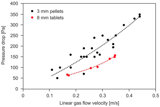
Figure 1.
The dependence of the tail-gas pressure drop across the deNOx catalyst beds in the form of extrudates (ϕ = 3 mm) and tablets (ϕ = 8 mm) on the linear gas flow velocity (own research).
The influence of the catalyst shaped body dimensions, bed porosity, shape factor and linear gas flow velocity on the pressure drop value can be determined based on the Ergun Equation (10):
- H—height of the catalyst bed, m
- ΔP—pressure drop of a gas flow through the catalyst bed, Pa
- V—linear gas flow velocity, m/s
- x—hydraulic diameter of the shaped catalyst body, m
- ε—bed porosity,
- ρf—density of the gas flowing through the catalyst bed, kg/m3,
- μ—gas viscosity, Pa·s.
For the shaped catalyst bodies, slightly differing from the shape of a sphere, the Blake–Kozeny–Carman and Plummers coefficients are equal to A = 150 and B = 1.75. The hydraulic diameter can be determined from Equation (16):
- Vi—volume of the shaped catalyst body, m3
- Si—surface of the shaped catalyst body, m2.
The average catalyst bed porosity can be determined based on the volume of the catalyst bed, mass and density of the shaped catalyst body, according to Equation (17):
The higher gas flow resistances promote better gas distribution over the catalyst bed. On the other hand, it is associated with less energy recovery in the expansion turbine, which translates into higher operating costs. The linear gas flow velocity affects the rate of catalytic reaction that runs in the diffusion regime, i.e., in the presence of the shaped catalyst. By lowering it, the efficiency of the deNOx and deN2O processes can be increased [26,61,62,63,64,65].
When developing the technology for the tail gases purifying from nitrogen oxides, the following aspects should be taken into account: the minimum N2O and NOx conversion expected by the industrial customer, or required to meet the applicable emission standards, the allowable pressure drop across the catalyst bed, and in case of using reducers, their permissible concentration in the purified gas stream (e. g. ammonia slip). On this basis, it is possible to select the appropriate type and/or shape of catalysts for N2O decomposition/reduction and NOx reduction, and determine the catalytic reactor design. The design of the reactor interior determines the value of the gas pressure drop across the catalyst bed and the linear gas flow velocity through the bed, which influences the efficiency of the catalyst operation. The assumed permissible pressure drop values across the catalyst bed are: ≤0.005 bars for low-pressure nitric acid plants (0–2 bars), ≤0.015 bar for the medium-pressure (3–6 bars), and ≤0.1 bar for the high-pressure ones (7–12 bars) [66].
3. Various Aspects of Designing Reactors for Purifying the Tail Gases from N2O and NOx
Several aspects should be considered when designing a reactor for the nitrogen oxides removal from the tail gases emitted from nitric acid plants:
- The required reactor size (dependent on a gas flow rate and catalyst activity);
- The gas temperature at the reactor inlet, required for the effective catalyst operation (eventually, selection of a heat exchanger for the tail gases preheating before they enter the catalytic reactor);
- The allowable gas flow resistances across the catalyst bed;
- Permissible content of nitrogen oxides downstream of the deNOx/deN2O reactor;
- Method of the tail gases purifying from the nitrogen oxides (selective or non-selective catalytic reduction of N2O, direct catalytic N2O decomposition);
- The method of mixing the tail gases with a reducing agent (selection of the static mixer) and distributing of this mixture inside the reactor [67,68];
- The arrangement (sequence) of the catalyst beds in reactors for simultaneous purifying of the tail gases from N2O and NOx and a method of reducing agent introduction upstream of the second catalyst bed;
- The available free space in the technological line of HNO3 plant, in which the reactor could be installed (downstream of the absorption column).
The process of reactors designing is often supported by numerical calculations (CFD—Computational Fluid Dynamics). They allow for optimising the proposed solution or determining the distribution of gas velocity, pressure and temperature or the degree of reactants conversion within the reactor volume for different reactor design solutions. The CFD method enables to simulate the influence of key process parameters on the efficiency of the NOx reduction process, such as temperature, NH3/NOx molar ratio and GHSV. Ansys Fluent, OpenFOAM, or Comsol Multiphysics software can be used to simulate the gas flow throughout the reactor. When building a reactor model that would best reflect the actual process conditions, the following factors should be taken into account: reactor design, the process of ammonia with the tail gases mixing, mass and heat transfer processes in a multi-component system, as well as the main chemical reactions. Due to the slight temperature difference between the outlet and inlet of the reactor, the modelled system can be treated as an adiabatic. The computational domain, reflecting the interior of the modelled reactor, is built based on the spatial dimensions of the existing or designed reactor (2D axisymmetric modelling or 3D modelling in the COMSOL program). It is divided into many subdomains, within which the CFD equations are discretized (e.g., by GAMBIT software) and calculated. It is crucial to select the correct geometry of the mesh elements (e.g., cuboid, tetrahedron, prism, pyramid), the number of subdomains and their sizes, which affect the accuracy of the calculations. The computational mesh is densified in the area of higher turbulence. Then, boundary, initial and operating conditions (based on industrial practice) are determined. The model parameters can be determined from the experimental results, using an optimization procedure based on a Taguchi method (used to design the experiment), a real-coded genetic algorithm (to search for optimal solutions) and a shape-tunable neural network (to bind the operational data together). The gas flow through the catalyst bed can be modeled as a compressible and viscous fluid flow through a porous medium. A k-ε turbulent flow model, e.g., of the RANS type (Reynolds-Averaged Navier–Stokes), as well as the equations of continuity and conservation of mass, momentum and energy can be used. The fixed bed reactors are modelled as a plug flow or axially dispersed plug flow. The gas density, dynamic viscosity, temperature, pressure and composition are determined based on the characteristics of the real gas. For most catalyst beds, the gas flow is considered as turbulent, except for the flow inside the monolith chanels, where it is treated as laminar. The main chemical reactions rates, involving NO and NH3 reactants, can be determined using the Chae kinetic model. To consider the reactor porosity, i.e., to obtain information on the permeability and pressure drop across the catalyst bed, the Ergun, Darcy–Forchheimer or Brinkman equations are also applied. The pressure equation can be obtained by combining continuity and momentum conservation equations. To solve the equations mentioned above, the appropriate solvers are used, depending on the nature of the fluid flow (laminar or turbulent, compressible or incompressible), the type and quantity of flowing media or the degree of gases mixing. A possible heat exchange should also be taken into account. The examples of solvers, that can be used, are: linear and non-linear solvers (pressure-based or density-based), fully coupled stationary solver with Direct module—UMFPACK, PCG—preconditioned (bi)-conjugate gradient solver for symmetric matrices, PbiCG—preconditioned stabilized (bi)-conjugate gradient solver for arbitrary matrices, smooth Solver—function smoothing, GAMG solver—using a generalized multi-mesh geometric-algebraic method, diagonal—for explicit methods, DIC with buffering—accelerated incomplete Choleski factorization, etc. [58,63,65,69,70,71].
The deNOx/deN2O reactor is a vertical apparatus installed on a steel supporting structure, inside which the catalyst bed is installed. Depending on the route of the tail gases pipeline and the available space in the technological line of nitric acid manufacturing, the arrangement of the reactor can be downflow or upflow. The gas inlet and outlet can be located in the upper and lower part of the reactor or on its side wall. Inside the reactor, the following zones can be distinguished:
- -
- Reducing agent injection (this zone can be located upstream of the reactor or inside it);
- -
- Reactor inlet with possible internal elements improving gas flow distribution over the catalyst bed or tail gases mixing with reducing agent;
- -
- Reaction zone with the catalyst bed;
- -
- Reactor outlet.
The efficiency of the SCR process is more remarkable the more homogeneous the gas flow field inside the reactor, and the more even the ammonia concentration distribution in the tail-gas stream. NH3 concentration profile in the tail-gas stream should be similar to the NOx concentration profile. To ensure a homogeneous gas flow field (conditioning of the gas flow) upstream of the catalyst bed, perforated plates, baffle plates, rectifying grids, guide vanes/plates or flow rectifiers are often installed inside the reactor. In the ammonia injection zone, static mixers can be installed. Flow rectifiers are used to ensure such a ratio value of the channel opening hydraulic diameter to the length of the gas flow path to create vertical flow lines upstream of the catalyst bed. Static mixers affect the flow structure by generating secondary cross-flow vortices and turbulent flow, increasing the mass and heat transfer in the cross-section of the pipeline/reactor while maintaining low-pressure drops. It can be a hollow pipe with openings or a channel with baffles mounted inside: straight, angled, corrugated or helical (Komax Custody Transfer, Kenics, Ross Engineering, Chemineer, Sulzer, JLS International). Static mixers can be of various types, e.g., made of metallic foam or suitably shaped sheets installed in the inlet section of the reactor (Iso Swirl, Shear, Swirl-Shear and Vortex mixers) [72,73,74,75,76].
Figure 2a,b show two simple static mixers: a pipe with holes and a helix-shaped sheet mounted inside the pipe. The red arrow marks the inlet of the reducing agent.
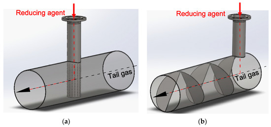
Figure 2.
Two types of static mixers: (a) a pipe with holes; (b) a helix-shaped sheet. The inlet of ammonia is marked with a red arrow. The tail gases flow through the main pipe.
The catalyst bed is mounted on a supporting steel structure in the reaction zone. It consists of load-bearing elements, permanently fixed to the reactor wall, and a basket resting on them. The shape of the catalytic basket is usually cylindrical, annular or a rectangular cassette. In the case of the axial tail-gas flow, it can also be a perforated plate placed at the bottom of the reactor. The design of the catalytic basket should ensure even gas distribution over the catalyst bed and mechanical integrity of the supporting structure. It should also enable the catalyst bed to be maintained stable throughout the entire period of operation and be resistant to rapid temperature changes or thermal shock (especially during emergency shutdowns of the plant). The catalytic basket may also contain vertical or diagonal plates, forcing a change in the flow direction of the gas stream.
When designing the reactors, the stresses of the reactor’s elements, natural frequency, local and general buckling modes induced by uniform compressive, bending and shear forces should be considered. deNOx and deN2O reactors are subject to thermal expansion, contraction and vibrations caused by the gas flow or operation of various devices in their immediate vicinity. The choice of reactor construction materials depends on the required material strength, corrosion resistance and process economy. The key parameters of the steel are a creep and fatigue strength and yield strength under process conditions, which are mainly temperature dependent. If the steel temperature does not exceed 454 °C, ordinary carbon steel can be chosen as the reactor construction material (above this temperature, steel graphitization occurs and the creep strength decreases). If it is higher, low-alloy steels with the addition of chromium and molybdenum should be considered. AISI-304L steel is often selected as the construction material for deNOx/deN2O reactors. A-387 alloy steel can also be used due to its resistance to creep, graphitization and oxidation. The reactor should be insulated from the environment to maintain the temperature of its walls above the dew point temperature of HNO3 (protection against corrosion when the nitric acid plant is shut down). The insulation also protects the hot reactor surface against contact with cold water from the rain (the material is then susceptible to bending and cracking) [72,74,75,77,78,79,80].
The choice of the reactor type depends on several factors: the rate of a chemical reaction under given process conditions, heat transfer, the influence of external diffusion resistance on the catalyst selectivity and the degree of reactants conversion. The main types of fixed bed deNOx/deN2O reactors used in nitric acid plants are axial, radial and lateral.
3.1. Axial Flow Reactor
The gas stream flows through the catalyst bed parallel to the reactor axis in axial flow reactors. The catalyst bed is installed in a cylindrical basket or on a perforated plate placed at the bottom part of the reactor. This design allows more space inside the reactor for the catalyst bed installation. If a cylindrical basket is used, it is necessary to seal it around the reactor perimeter to avoid gas by-passing.
The use of a seal is not required when the catalyst bed rests on a perforated plate and is in contact with the side walls of the reactor. Figure 3a,b show an exemplary interiors of the deNOx/deN2O reactor, with the construction that forces the axial flow of the tail-gas stream through the catalyst bed. The black arrow shows the direction of the purified gas flow schematically. A perforated plate, installed upstream of the catalyst bed (1), is used to improve gas distribution over the catalyst bed.
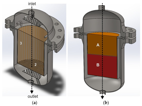
Figure 3.
Reactor for heterogeneous catalytic processes with a structure, that forces the axial gas flow through the catalyst bed. (a) Reactor interior with an empty catalytic basket: 1—perforated plate improving mixing of ammonia with the tail gases, 2—bottom perforated basket wall, 3—solid side wall of the basket. (b) Catalytic basket with a double catalyst/s bed: A—deNOx catalyst bed, B—deN2O catalyst bed.
To increase the gas purification efficiency in an axial flow reactor, without increasing the gas flow resistances, the diameter of the reactor should be increased. However, this requires using a thicker, heavier and more expensive reactor shell, which will be subject to faster exploitation. When designing a reactor with a larger diameter, the plant’s production capacity and the efficiency of the media transport equipment should be considered.
The advantages of the axial flow reactor are the easy loading and unloading of the catalyst and the simple design of the catalytic basket. With the same space inside the reactor, a larger catalyst bed volume can be installed in the cylindrical basket compared to the other solutions (described below). It is due to the absence of additional baffles and empty spaces, constituting the zone of the gas inflow onto the catalyst bed. Reactors with a design that forces the axial gas flow through the catalyst bed generate greater pressure drops compared with reactors in which the gas flows through the bed perpendicular to the reactor axis (radial or lateral flow). In addition, they are characterized by a higher linear gas flow velocity, which translates into a lower conversion of nitrogen oxides in relation to the radial or lateral flow reactor. In the axial flow reactor, the pressure drop and catalyst efficiency can be influenced by changing the form and size of the shaped catalyst body.
In axial flow reactors, monolithic catalysts can be installed (e.g., CuO-NiO on a ceramic monolith based on alumina-silicates, BASF O4-85 catalyst based on vanadium oxide) without fear of too-high pressure drops. Their specific “architecture” enables high efficiencies of the tail gases purifying from nitrogen oxides at the low pressure drops [61,65,81,82,83,84,85].
When using a dual-bed catalytic system, e.g., deNOx/deN2O, the catalyst beds can be installed inside one catalytic basket and separated from each other by a perforated plate or gauze (mesh size should be smaller than the size of the shaped catalyst body). The deNOx catalyst bed should be placed in the upper part of the catalytic basket, while the ammonia is mixed with the tail gases before entering the reactor. If the arrangement of the catalyst beds is changed, they should be separated from each other by a space, into which gaseous ammonia is introduced and mixed with the tail-gas stream. The gaseous ammonia pipeline would then be installed on the side wall of the reactor. Ammonia could be introduced into the gas stream using an ammonia injection grid.
The construction of the catalytic reactor, operating in the axial flow mode, can be easily converted into the axial–radial or radial flow mode, without significantly modifying the reactor interior. Such modification, however, reduces the space available for the catalyst bed.
3.2. Radial Flow Reactor
The radial gas flow reactor has a more complex design than the axial flow one and the catalytic basket has an annular shape. The side walls of the basket are perforated, while its lower part is gas-impermeable. After loading the catalyst into the basket, a solid top cover plate is installed, the side walls of which are usually several centimetres high. They protect the basket against gas bypassing in the event of catalyst bed settling (e.g., due to catalyst sintering or settling the bed under its weight). The gas stream entering the reactor first flows in the axial direction, and it hits the top cover plate of the catalytic basket. Then, it enters the annular space between the reactor wall and the side wall of the basket. It flows radially through the catalyst bed into the central tube, through which it exits the reactor. The gas flow through the catalyst bed should be mainly radial, preferably with no axial velocity component. The share of axial velocity components may cause an effect similar to “back-mixing”, reducing the gas purification efficiency (mixing of gas streams with different degrees of reactants conversion). In radial flow reactors, two gas flow directions are possible: from the central part of the reactor towards its side walls or from the annular space between the basket and the reactor side wall to the central part of the reactor, through which the gas leaves it.
Figure 4a,b show the interior of a radial reactor with a single empty annular catalytic basket and two annular catalytic baskets with NOx and N2O catalyst beds. The black arrows show one of the possible directions of the gas flow through the catalyst basket. The tail gases mixed with the reducing agent are fed to the reactor through the inlet. A large part of the gas stream hits the top cover plate of the catalytic basket and changes direction. Then, it enters the space between the reactor and basket side walls. The gas stream flows radially through the annular-shaped catalyst beds to the central pipe and exits the reactor at the outlet. The inner side wall of the outer annular basket is simultaneously the outer side wall of the inner annular basket. To ensure radial flow, the bottom part of the catalytic basket is gas-impermeable, and the upper part is closed by the top cover plate, while the side walls are perforated.
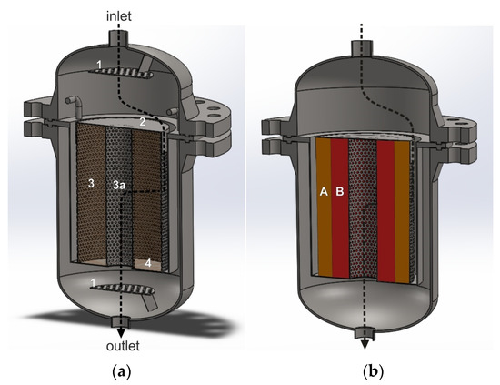
Figure 4.
Reactor for heterogeneous catalytic processes with a structure that forces radial gas flow through the catalyst bed. (a)—basket with one annular space, in which one catalyst bed can be installed: 1—perforated plate improving gas flow distribution and mixing, 2—solid top cover plate, 3—outer perforated side wall of the basket, 3a—perforated inner side wall of the basket, 4—solid bottom plate of the basket. (b)—dual-bed catalytic system: A—deNOx catalyst bed, B—deN2O catalyst bed.
When designing radial flow reactors, certain conditions should be taken into account:
- It is necessary to ensure uniform gas distribution over the catalyst bed, along the entire length of the catalytic basket to achieve higher nitrogen oxide conversion (uneven gas distribution results in uneven exploitation of the catalyst bed and basket, which may lead to corrosion);
- Settling of the catalyst bed during operation may result in an empty space formation in the upper part of the bed and gas bypassing. In total, 5–20% excess of the catalyst bed should be used in relation to the amount required to achieve the assumed nitrogen oxides conversion, compensating for bed settlement. This amount depends on the mechanical properties of the catalyst and the number of plant shutdowns and start-ups;
- In a radial reactor, a sufficient space between the reactor and the basket side wall should be ensured to distribute the gas stream over the catalyst bed evenly;
- When two or more catalyst beds are used, the deNOx catalyst bed should be placed in the outer annular basket (inward flow of the gas stream). In a radial flow reactor with a co-axial arrangement of the annular catalytic baskets along the reactor diameter, it is not possible to introduce a reducing agent upstream of the second catalyst bed.
Radial flow reactors can be used for high gas flow rates through the catalyst bed, where it is required to purify large amounts of gas per unit time while ensuring low pressure drops. This reactor provides lower gas flow resistances across the catalyst bed, compared with the axial ones, for the same volumetric gas flow rate. The efficiency of tail-gas purification from the nitrogen oxides in the radial reactor can be increased by increasing the reactor length. Despite the greater height of the bed, its lower thickness ensures a lower gas pressure drop. Such a reactor design enables the use of smaller sizes of the shaped catalyst bodies, which allow increasing the efficiency of the deNOx/deN2O technology without fear of excessive pressure drop.
In a radial reactor, the catalyst bed settles during operation, and an empty space may form in the upper part of the bed, constituting a path of gas bypassing. It is, therefore, important to seal the catalyst bed in this area so that the gas does not reach the upper edge of the catalyst bed in the catalytic basket. The upper part of the catalyst bed is usually shielded by a gas-impermeable top cover plate. This part of the bed serves as a seal and is not used in gas purification. Using an excess catalyst as a sealing layer increases the cost of the apparatus and the deNOx/deN2O technology. Using a top cover plate of suitable weight and design also generates additional costs compared with the axial reactor.
The radial reactor provides more efficient use of the available reaction zone than the axial one, while lower pressure drops translate into higher energy recovery in the expansion turbine. This design also has disadvantages. Catalyst loading and unloading in the radial reactor is more complicated and time-consuming. In addition, there is a need to install or remove the basket’s top cover plate. Due to the low gas flow resistances, there can also be a problem with the uniform gas distribution over the catalyst bed, along the length of the reactor. Thus, the longer the reactor is, the poorer the gas distribution along the height of the basket. A way to slightly increase the flow resistance is to use a suitable design of basket walls in the upper and lower part of the catalyst bed. They should ensure a higher gas flow resistance in the upper part of the catalyst bed (near the top cover plate) and lower gas flow resistance in the lower part of the catalyst bed. This reduces gas recirculation in the annular space between the reactor and perforated side walls of the basket, as well as in the central part of reactor. The gas flow resistance through the perforated basket walls can be varied by, e.g., the use of different hole sizes and varying their location (the basket walls can be made of Vee Wire or Johnson screens).
Radial reactors are often offered to nitric acid producers by BASF as part of the SCR-deNOx technology. Most often, catalysts based on vanadium oxide on TiO2 support or iron-modified zeolites in the form of extrudates are installed in them [35,61,65,80,84,86,87,88,89].
Radial Flow Reactor with Triple-Bed Catalytic System
The catalyst beds in the radial flow reactor can be installed in the three annular baskets, arranged coaxially along the reactor’s diameter and/or axis. Casale proposed such a solution. It consists of a three-stage tail-gas purification from the nitrogen oxides in one reactor, including NOx reduction with ammonia on the first and third catalytic beds and N2O decomposition on the second catalytic bed. This solution may be advantageous if iron-modified zeolite catalysts are used in deN2O process, for which the co-catalytic effect of the NOx presence on N2O decomposition has been found.
Figure 5 shows an exemplary arrangement of deNOx and deN2O catalyst beds in a radial reactor, according to the Casale solution.
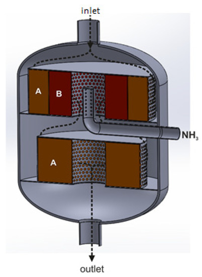
Figure 5.
Radial reactor with triple-bed catalytic system, with catalytic beds arranged co-axially along the reactor’s diameter and axis: A—deNOx catalyst bed, B—deN2O catalyst bed (based on patent [56]).
The direction of the tail-gas flow across the reactor is shown by black arrows. The reducing agent is introduced into the tail-gas stream upstream of the first and third catalyst beds. On the first deNOx catalyst bed, the NOx content in the gas stream is reduced to 50–200 ppm. The presence of these oxides upstream of the second catalyst bed increases the efficiency of N2O decomposition (the following reaction occurs: NO + N2O → NO2 + N2). The tail-gas stream leaving the deN2O catalyst bed is collected in a central collector, to which another portion of the reducing agent, necessary to reduce NOx concentration to 25 ppm, is introduced.
The use of the Casale solution allows for reducing NOx (vanadia-titania or Fe-zeolite catalyst) and N2O (Fe-zeolite catalyst) emissions to the levels of <25 ppm and <30 ppm (efficiency >95%), respectively, with ammonia slip no greater than 2 ppm. Its advantage is the more efficient use of the reducing agent (ammonia) and the possibility of using part of the NOx amount in the N2O decomposition process. The disadvantage is the complex design of the reactor, which hinders the operation of loading and unloading catalysts to the baskets. Additionally, the ammonia injection/dosing, and the control and measurement system are more complex. It is necessary to install two separate ammonia injection zones, use an additional measurement point of NH3 and NOx concentration in the tail-gas stream (between the second and third catalyst beds), as well as another other device to control the amount of ammonia introduced upstream of the third catalyst bed [56,90].
The radial reactor, with a construction similar to the Casale solution, can also be used in the EnviNOx technology. Figure 6a,b show an exemplary arrangement of deNOx and deN2O catalyst beds for the first and second variants of the EnviNOx processes. In the first case, a mixture of ammonia and tail gases are introduced into a catalytic reactor and directed to the deNOx catalyst bed. After reducing the NOx, the gas flows through the deN2O catalyst bed, where direct catalytic N2O decomposition occurs. The use of the deNOx process in the first stage of tail-gas purification is advantageous. As a result of this process, the temperature of the purified gas increases before it enters the deN2O catalyst bed.
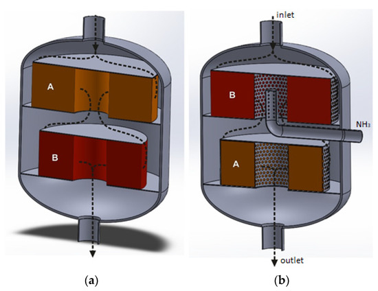
Figure 6.
Radial flow reactors with a dual-bed catalytic system, where catalyst beds are arranged coaxially along the reactor axis. It can be used in the first variant (a) or the second variant (b) of EnviNOx processes. A—deNOx catalyst bed, B—deN2O catalyst bed.
For the second variant of the EnviNOx process, the deN2O catalyst bed is installed in the upper annular catalytic basket, while the deNOx catalyst is installed downstream of the deN2O catalyst bed. In this case, it is necessary to use two types of reducing agents, so there are two possibilities. Hydrocarbon and tail-gas mixtures are introduced into the reactor to reduce N2O on the first catalyst bed, while ammonia (for NOx reduction) is introduced into the space between the deN2O and deNOx catalyst beds (Figure 6b). Another possibility is to introduce a mixture of tail gases with both reducing agents. Figure 6 shows one possible way of injecting ammonia into the gas stream. It is also possible to install an ammonia injection grid inside the reactor, upstream of the deNOx catalyst bed. NH3 could then be supplied through a pipeline installed on a side wall of the reactor.
3.3. Radial Flow Reactor with Deflectors
The flow direction in a radial flow reactor can be modified by introducing a deflector in the central part of the reactor and in the spaces between the catalyst beds (in case of using more than one concentric annular basket inside the reactor). Figure 7a,b show a radial flow reactor with several annular deNOx and deN2O catalyst beds and deflectors arranged between them. The deflectors direct the gas stream radially through the catalyst beds without generating significant gas flow turbulence and ensure uniform gas distribution over the catalyst bed. The central deflector has the shape of an inverted cone, while the other deflectors have a form of a truncated cone with a parabolic outer surface. The lower edge of these deflectors is connected to the lower edge of the inner annular basket with the catalyst bed. The upper edge of the deflectors is connected to the upper edge of the outer annular basket. The deflector extends from the upper edge of the catalyst bed to the lower edge of the adjacent catalyst bed.
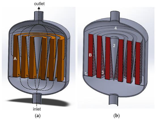
Figure 7.
Radial flow reactor with deflectors for heterogenous catalytic processes (based on patent [91]): 1—solid plate constituting the bottom part of the basket, 2—deflectors, 3—perforated side wall of the basket, 4—gas-impermeable upper wall of the basket, A and B—deNOx (a) and deN2O (b) catalyst beds.
The purified gas stream, fed to the reactor’s lower stub pipe, flows into the space between the catalyst beds, where it is deflected by the deflector walls and directed radially through the catalyst bed. Then, the gas stream is deflected on the outer wall of the next deflector and flows to the reactor outlet.
Compared with a classic radial flow reactor, the deflectors make it possible to extend the flow path of the gas before it enters the catalyst bed. This improves gas distribution over the catalyst beds, along the reactor axis, and ensures a gentle inflow of the gas stream onto the bed. The pressure drops across the catalyst bed in a radial-flow reactor with deflectors are about ten times lower than in the axial one, using the same total volume as the catalyst bed. However, additional elements in the form of deflectors are also an expensive option.
So far, this type of reactor has been used for purifying the tail gases generated in the fuel combustion processes [91].
3.4. Radial–Axial Flow Reactors
Many methods of deNOx and deN2O catalyst beds arrangement in the reactor for purifying the tail gases from nitrogen oxides are described in the patent literature. These are mainly ThyssenKrupp Uhde and Casale solutions. Some of them concern the use of two different catalyst bed configurations, forcing the gas stream to flow in both radial and axial directions.
Figure 8a,b show two variants of the catalytic reactor in a longitudinal section with two catalyst beds. The black arrows indicate the direction of the gas flow. In the first case, the tail gases mixed with ammonia are introduced onto the deNOx catalyst bed, which forces it to flow in the axial direction (the upper and lower part of the catalytic basket is perforated, while the side walls are gas-impermeable). The tail-gas stream, purified at the first stage from NOx, flows to a space surrounded by the deN2O catalyst bed installed in the annular basket. The side walls of the basket are perforated, while the top and bottom parts are gas-impermeable. The gas stream flows radially through the deN2O catalyst bed from the central part of the reactor towards its side walls and is directed to the outlet. This type of reactor could be used for conducting the EnviNOx process according to variant II. In this case, tail gases mixed with ammonia would be fed to the reactor (the first gas purification stage—deNOx process). A hydrocarbon would be introduced into the tail gases upstream of the second bed—deN2O catalyst.
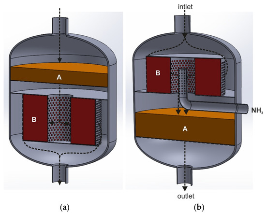
Figure 8.
Reactors for conducting heterogeneous catalytic reaction with the dual-bed catalytic system (A—deNOx catalyst bed, B—deN2O catalyst bed), forcing the gas to flow both in the axial and radial direction: (a)—axial–radial flow, (b)—radial–axial flow (based on patent [35,92]).
The second variant of the catalytic reactor (Figure 8b) could be used in the I variant of the EnviNOx process. The tail gases initially flow along the reactor axis, hit the top cover plate and enter the annular space between the reactor and perforated side walls of the catalytic basket. The tail gases flow radially through the deN2O catalyst bed, on which direct catalytic N2O decomposition occurs. In the central collector, they are mixed with ammonia and directed axially to the deNOx catalyst bed, placed in a cylindrical basket. In Figure 8b, one of the methods of introducing ammonia to the space between the two catalyst beds is shown (pipe with holes). It can also be an ammonia injection grid.
The flow of the tail gases in the axial–radial direction can also be realized by installing the annular baskets coaxially along the reactor diameter (Figure 9). Contrary to the solutions presented in Figure 8a,b, both catalyst beds (deNOx and deN2O) are installed in the annular catalytic baskets. The side walls of the catalytic baskets and the top plate are perforated, while the bottom walls are gas-impermeable. The first catalyst bed is in the outer basket and the upper part of the inner annular basket.
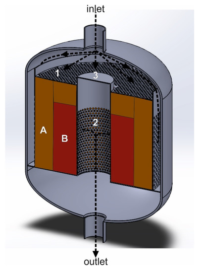
Figure 9.
Reactor with the dual-bed catalytic system, forcing the gas to flow in the axial–radial direction: 1—perforated upper wall of the basket, 2—perforated side wall of the basket, 3—gas-impermeable upper central wall of the basket, A—deNOx catalyst bed, B—deN2O catalyst bed (based on patent [88]).
The second catalyst bed is in contact with the first catalytic bed through the perforated side walls of the basket. However, in the upper part it is separated from the layer of the first catalyst bed by a solid baffle/plate. The purified gas stream flows through the first catalyst bed (deNOx) in the axial and radial direction, while through the second catalyst bed (deN2O) only in the radial one. Then, it is collected in the central space of the reactor and directed to its outlet. The reducing agent (ammonia or ammonia + hydrocarbon) is mixed with the tail-gas stream before entering the first catalyst bed. The top layer of the first catalyst acts as a sealing layer, preventing the gas stream from bypassing (in case of settling of the catalyst bed, see Section 3.2) and simultaneously participates in the reaction. This solution ensures a more even gas distribution over the catalyst bed, does not require installing a heavy top cover plate in the upper part of the basket and using an excess catalyst layer, which only serves as a sealing of the catalyst bed.
Mixed-flow reactors with axial and radial gas flow direction through the catalytic baskets ensure lower operating and capital costs than those with two catalyst beds arranged in annular baskets. It also allows for better use of the space inside the reactor (with the same volume of available space inside the reactor, more catalyst can be installed in the cylindrical basket compared to the annular one) and combines the advantages of the axial and radial gas flow through the catalytic reactor. It is crucial for the catalysts, whose activity under given process conditions depends to a greater extent on the amount of catalyst bed (kinetic regime) than how the gas flows through it (linear gas flow velocity). The first catalyst bed ensures at least partial flow of the gas stream in the axial direction and acts as a layer protecting the catalyst bed against a gas bypassing. It occurs in the annular baskets as a result of the catalyst bed settling. Hence, the catalyst bed is sealed in the upper part using a top cover plate, whose side walls are even several centimetres wide. The weight of such a construction is greater than that of the basket, forcing the gas flow in the axial direction. Suppose a first catalyst bed, installed in the upper part of the reactor, forces the gas flow in an axial direction. In that case, a lighter top cover plate can be used over a second catalytic basket of annular shape (two catalyst beds arranged coaxially along the reactor axis, spatially separated). The catalyst bed in the upper part of the reactor will provide a smoother tail-gas inflow onto the second catalyst bed. In addition, a mixed gas flow will be created within the second catalyst bed, including axial and radial velocity components, which provide a better gas distribution over this bed. Installing one of the catalyst beds in the annular catalytic baskets ensures a lower gas pressure drop than the solution with two catalyst beds through which the gas flows in the axial direction. In the case of the catalyst beds arrangement, in which the gas stream flows through the catalyst beds first in the radial and then in the axial direction, back-mixing may occur. The bed installed in the annular catalytic basket generates lower gas flow resistances in relation to the bed in the cylindrical catalyst basket.
In the catalytic basket, by forcing gas flow in the axial direction, a catalyst with a higher activity under given process conditions can be installed. This allows the use of shaped catalyst bodies of a larger size, ensuring lower gas pressure drops across the catalyst bed. A less active catalyst can be installed in a catalytic basket with an annular structure, in which, due to the lower gas flow resistances, smaller catalyst bodies can be installed [35,88,92,93].
3.5. Lateral Flow Reactor
In the lateral flow reactor (LFR), as in the radial one, the gas flow direction through the catalyst bed is perpendicular to the reactor axis. Therefore, it is characterized by a lower linear gas flow velocity through the catalyst bed than the axial flow reactor. The catalytic basket of the LFR reactor consists of a series of cassettes of small width, the side walls of which are perforated, while the top and bottom parts are gas-impermeable (Figure 10). This design allows only for installing one type of catalyst. Therefore, it is impossible to combine the two catalytic processes, deNOx and deN2O.
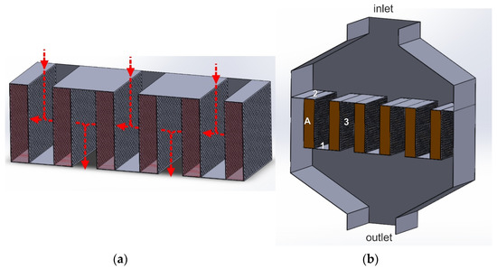
Figure 10.
(a,b) Lateral flow reactor (LFR): 1—solid bottom plate of the basket, 2—solid upper part of the basket, 3—perforated side walls of the cassette, A—cassette with a catalyst bed.
The tail-gas stream can be introduced in the top or bottom part of the reactor. It initially flows in the axial direction into the space between the two catalyst beds. Then, it hits the solid plate installed between the two cassettes in their upper part and flows through their perforated side walls. After passing through the catalyst bed, the gas stream exits the cassette through the second perforated wall and joins with the gas stream from the adjacent cassette. The gas streams from the spaces between the cassettes merge and leave the reactor through the outlet. The gas stream inside the cassette flows quite slowly, which to some extent, limits the mass and heat exchange between the gas phase and the catalyst surface. Therefore, LFR reactors are used for low-rate reactions, especially those running mainly in the kinetic regime.
CFD calculations of the LFR reactors are performed to assess the reactor’s geometrical parameters and the operating conditions impact on the hydrodynamic properties, i.e., gas pressure drops across the catalyst bed or flow velocity distribution (transverse/lateral) along the catalyst bed height. They are also used to estimate the friction factor against the walls of the channels between the cassettes.
In LFR reactors, the pressure drop does not exceed 2 kPa. Typically, it is in the range of 0.1–2.0 kPa at a gas flow rate of 2000–50,000 Nm3/(m3 h), and cassette dimensions of height × depth × width = (0.5 ÷ 2.0) × (0.5 ÷ 2.0) × (0.02 ÷ 0.1) m. A low pressure drop (especially at a level of several hundred Pa) translates into a poorer gas distribution over the catalyst bed, along the height of the cassette (uneven distribution of transverse/lateral velocity). The uniformity of the gas flow through the LFR reactor can be improved by using very small catalyst bodies or by increasing the width of the cassettes. However, this translates into investment costs increase. The total pressure drop value is also affected by the friction factor, which depends on the roughness of the channel walls [94,95,96,97].
Shell company offeres the LFR reactors as a Shell DeNOx system technology. Titania-supported vanadium oxide catalysts in the form of trilobes, with dimensions 0.6–5.0 mm (S-096), are installed in them.
The design of the LFR reactor ensures very low gas flow resistances across the catalyst bed (lower than in the axial or radial flow reactor). Therefore, installing very small catalyst bodies without the risk of excessive pressure drop value is possible. In this type of reactor, high efficiency of the gas purification from nitrogen oxides is achieved, exceeding 95% (Shell deNOx System, titania/vanadia catalyst). A particular problem is the uneven gas distribution along the length of the cassettes. The construction of the catalytic basket is quite complicated, as it consists of a series of perforated and solid plates, directing the flow of the gas stream. Unloading and loading the catalyst into the cassette is also problematic due to their large depth and small width. To better compact the catalyst bed in the cassette, it is necessary for example to load it in batches and vibrate the bed. However, such a procedure may contribute to catalyst crushing.
3.6. Parallel-Flow Reactor with Deflectors
A modification of the LFR reactor is the parallel-flow reactor with deflectors, shown in Figure 11. Contrary to the solution in Section 3.5, the horizontal plates do not close the channels between adjacent catalyst beds. The cassettes with the catalyst bed are connected by deflectors fixed to the lower edge of one cassette and the upper edge of the other.
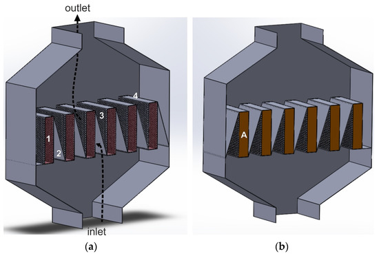
Figure 11.
(a,b) Parallel-flow reactor with deflectors (based on Patent [98]): 1—empty cassette, 2—deflector, 3—perforated side wall of the cassette, 4—gas-impermeable top wall of the cassette, A—catalyst bed.
The diagonal plates (deflectors) between the cassettes ensure a smoother gas inflow onto the catalyst bed, without generating significant turbulence in the gas flow. The residence time of the gas in the catalyst bed is also longer. At the cassette outlet, the deflectors gently deflect the gas stream towards the reactor outlet. Probably, they also contribute to reducing the friction factor (friction against the walls of channels) and declining the total pressure drop compared to the classic LFR reactor. On the other hand, the presence of deflectors makes the reactor design more complicated [98].
4. Conclusions
Table 1 presents the advantages and disadvantages of the three main design solutions of the catalytic baskets.

Table 1.
Advantages and disadvantages of the catalytic basket design in deNOx/deN2O reactors.
An overview of the deNOx/deN2O catalytic reactors design used in nitric acid plants, as well as the types of catalysts used in NOx and N2O reduction (NOx reduction—TiO2-supported vanadium oxide, NOx and N2O reduction—iron-modified zeolites) and direct N2O decomposition (iron-modified zeolites, zinc-cobalt spinel) were presented. Before installing in the reactor, the catalyst should be appropriately shaped. The catalyst shaped body affects the size of the geometric surface available for the reactants, mass and heat transfer between the catalyst surface and the gas phase, as well as the pressure drop. Catalysts in the form of spheres, extrudates, trillobes and monoliths are often used in nitric acid plants in deNOx/deN2O reactors.
The efficiency of tail-gases purification from nitrogen oxides is affected not only by the type and shape of the catalyst, but also by the method of its installation inside the reactor (design of the catalytic basket). Various aspects of designing deNOx/deN2O reactors were described, including modelling their operation using CFD calculations. Several types of reactors that can be used in nitric acid plants, differing in how the gas stream flows through the catalyst bed, were presented. Three main types of reactors, which are the basis for other design solutions, are axial, radial and lateral flow reactors. In the first case, the gas stream flows through the catalyst bed in a direction parallel to the reactor axis, and the catalytic basket is often cylindrical. In the radial and lateral flow reactor, the gas stream flows in a direction perpendicular to the reactor axis and the catalytic basket has an annular shape or rectangular cassettes, respectively. The lowest gas flow resistances and the highest efficiency in tail-gas purification from nitrogen oxides (in the case of catalyst in the form of grains) are provided by the lateral flow reactor. The limitation is the inability to integrate catalysts for deNOx and deN2O processes inside one reactor. For the proper operation of the lateral reactor, it is necessary to ensure an even gas distribution over the catalyst bed, along the height of the cassettes. The deflectors can be installed in the channels between the cassettes to: ensure a smoother gas inflow onto the catalyst bed, extend the gas flow path before it enters the catalyst bed, improve gas distribution over the bed along the height of the catalytic basket or reduce the total gas flow resistances through the reactor. However, this makes basket construction more complicated and problematic in the case of maintenance works. The deNOx and deN2O catalyst beds can be arranged in the reactor along the diameter of the reactor and its axis, in the cylindrical or annular catalytic baskets. Combining the axial and radial flow inside one reactor makes it possible to use the advantages of both design solutions (see Table 1).
Author Contributions
Conceptualization, P.C., M.R., M.I., M.W. and A.R.; Writing—original draft preparation, P.C. and M.R.; writing—review and editing, P.C., M.R., M.I., M.W. and A.R.; Supervision, M.R., M.W., M.I., A.R.; Investigations, P.C., M.I. and M.R. All authors have read and agreed to the published version of the manuscript.
Funding
P.C. acknowledge the financial support founded by the program of the Ministry of Science and Higher Education entitled “Implementation Doctorate”.
Institutional Review Board Statement
Not applicable.
Informed Consent Statement
Not applicable.
Data Availability Statement
Not applicable.
Conflicts of Interest
The authors declare no conflict of interest.
Abbreviations
| Symbols | |
| μ | viscosity of the gas flowing through the catalyst bed [Pa·s] |
| ε | bed voidage [m3] |
| density of the gas flowing through the catalyst bed [kg/m3] | |
| density of the shaped catalyst body [kg/m3] | |
| mw | mass of the shaped catalyst body [kg] |
| x | spherical equivalent particle diameter [m] |
| A | Blake–Kozeny–Carman coefficient |
| B | Plummer coefficient |
| H | height of the catalyst bed [m] |
| ∆P | pressure drop across the catalyst bed [Pa] |
| Si | surface of the catalyst body [m2] |
| V | linear gas flow velocity [m/s] |
| Vi | volume of the shaped catalyst body [m3] |
| Vtot | total volume of the catalyst bed [m3] |
References
- IPCC. The IPCC Finalized the Synthesis Report for the Sixth Assessment Report. In Proceedings of the Panel’s 58th Session, Interlaken, Switzerland, 13–19 March 2023. Available online: https://www.ipcc.ch/report/sixth-assessment-report-cycle/ (accessed on 24 April 2023).
- Tian, H.; Xu, R.; Canadell, J.G.; Thompson, R.L.; Winiwarter, W.; Suntharalingam, P.; Yao, Y. A comprehensive quantification of global nitrous oxide sources and sinks. Nature 2020, 586, 248–256. [Google Scholar] [CrossRef]
- Prather, M.J.; Hsu, J.; DeLuca, N.M.; Jackman, C.H.; Oman, L.D.; Douglass, A.R.; Funke, B. Measuring and modeling the lifetime of nitrous oxide including its variability. J. Geophys. Res. Atmos. 2015, 120, 5693–5705. [Google Scholar] [CrossRef] [PubMed]
- Wiser, A. Investigation of the Industrial NH3 Oxidation by CFD Simulations Including Detailed Surface Kinetics. Technische Universität: Darmstadt, Germany, 2020. [Google Scholar] [CrossRef]
- Groves, M.; Sasonow, A. Uhde EnviNOx® Technology for NOx and N2O abatement—A contribution to reducing emissions from nitric acid plants. In Proceedings of the Fifth International Symposium on Non-CO2 Greenhouse Gases (NCGG-5), Wageningen, The Netherlands, 30 June–3 July 2009; Available online: https://ucpcdn.thyssenkrupp.com/_legacy/UCPthyssenkruppBAIS/assets.files/download_1/nitrates/uhde_publications_pdf_en_15000012.pdf (accessed on 24 April 2023).
- Forster, P.; Ramaswamy, V.; Artaxo, P.; Berntsen, T.; Betts, R.; Fahey, D.W.; Haywood, J.; Lean, J.; Lowe, D.C.; Myhre, G.; et al. Changes in Atmospheric Constituents and in Radiative Forcing. Chapter 2. Environ. Sci. 2007, 39, 129–234. Available online: http://www.ipcc.ch/pdf/assessment-report/ar4/wg1/ar4-wg1-chapter2.pdf (accessed on 24 April 2023).
- Skalska, K.; Miller, J.S.; Ledakowicz, S. Trends in NOx abatement: A review. Sci. Total Environ. 2010, 408, 3976–3989. [Google Scholar] [CrossRef]
- Woodrow, P. Nitric oxide: Some nursing implications. Intensive Crit. Care Nurs. 1997, 13, 87–92. [Google Scholar] [CrossRef] [PubMed]
- Wark, K.; Warner, C.F. Air Pollution: Its Origin and Control, 3rd ed.; U.S. Department of Energy: Washington, DC, USA, 1997; ISBN 0-67399416-3. [Google Scholar]
- USP Technologies. Nitrogen Oxides (NOx) Abatement with Hydrogen Peroxide, Compiled in Part from FMC Technical Data, Pollution Control Release No. 119; Technical Bulletin of USP Technologies; USP Technologies: Atlanta, GA, USA, 2015; Available online: https://www.h2o2.com/industrial/applications.aspx?pid=101 (accessed on 24 April 2023).
- Juzsakova, T.; Al-Jammal, N.; Cretescu, I.; Sebestyén, V.; Le Phuoc, C.; Domokos, E.; Stan, C.D. Case studies for clean technology development in the chemical industry using zeolite based catalysts. Minerals 2018, 8, 462. [Google Scholar] [CrossRef]
- Council Decision (EU) 2017/1757 of 17 July 2017 on the Acceptance on Behalf of the European Union of an Amendment to the 1999 Protocol to the 1979 Convention on Long-Range Transboundary Air Pollution to Abate Acidification, Eutrophication and Ground-Level Ozone, Official Journal of the European Union. Available online: https://eur-lex.europa.eu/legal-content/EN/TXT/PDF/?uri=CELEX:32017D1757&from=ET (accessed on 24 April 2023).
- Reference Document on Best Available Techniques for the Manufacture of Large Inorganic Chemicals—Ammonia, Acids and Fertilisers. 2007. Available online: https://eippcb.jrc.ec.europa.eu/sites/default/files/2019-11/lvic_aaf.pdf (accessed on 31 December 2022).
- Emisja Gazów Cieplarnianych. Wybrane Zagadnienia Dotyczące Emisji CO2 w Polsce. 2020, OT-683, Warszawa. Available online: https://www.senat.gov.pl/gfx/senat/pl/senatopracowania/192/plik/ot-683.pdf (accessed on 24 April 2023).
- Bańkowska, K. Global Climate Agreement and Rural Development. Wieś Rol. 2016, 170, 87–104. [Google Scholar] [CrossRef] [PubMed]
- Raport z Rynku CO2. Available online: https://www.kobize.pl/pl/article/aktualnosci-2023/id/2257/raport-z-rynku-co2-styczen-2023 (accessed on 24 April 2023).
- Pérez-Ramırez, J.; Kapteijn, F.; Schöffel, K.; Moulijn, J.A. Formation and control of N2O in nitric acid production: Where do we stand today? Appl. Catal. B Environ. 2003, 44, 117–151. [Google Scholar] [CrossRef]
- Schwefer, M.; Seifert, R.; Fuchs, J.; Ruthardt, K.; Groves, M. Thyssenkrupp Industrial Solutions AG. Method for Removing N2O and NOx from the Nitric Acid Production Process, and an Installation Suitable for Same. U.S. Patent US20170334722, 23 November 2017. Available online: https://scholar.google.com/scholar_lookup?title=Method+for+Removing+N2O+and+NOx+From+the+Nitric+Acid+Production+Process,+and+an+Installation+Suitable+for+Same&author=Schwefer,+M.&author=Seifert,+R.&author=Fuchs,+J.&author=Ruthardt,+K.&author=Groves,+M.&author=Thyssenkrupp+Industrial+Solutions+AG&publication_year=2017 (accessed on 31 December 2022).
- Hevia, M.A.; Pérez-Ramírez, J. Assessment of the low-temperature EnviNOx® variant for catalytic N2O abatement over steam-activated FeZSM-5. Appl. Catal. B Environ. 2008, 77, 248–254. [Google Scholar] [CrossRef]
- Slyusarenko, A. Clariant emission control catalysts. In Proceedings of the SCIF Congress, International Online Symposium, Virtual event, 23–24 June 2022. [Google Scholar]
- Konsolakis, M. Recent advances on nitrous oxide (N2O) decomposition over non-noble-metal oxide catalysts: Catalytic performance, mechanistic considerations, and surface chemistry aspects. ACS Catal. 2015, 5, 6397–6421. [Google Scholar] [CrossRef]
- Isupova, L.A.; Ivanova, Y.A. Removal of nitrous oxide in nitric acid production. Kinet. Catal. 2019, 60, 744–760. [Google Scholar] [CrossRef]
- Inger, M.; Wilk, M.; Saramok, M.; Grzybek, G.; Grodzka, A.; Stelmachowski, P.; Sojka, Z. Cobalt spinel catalyst for N2O abatement in the pilot plant operation–long-term activity and stability in tail gases. Ind. Eng. Chem. Res. 2014, 53, 10335–10342. [Google Scholar] [CrossRef]
- Schwefer, M. Catalyst for Decomposing N2O, Its Use and Method for the Production Thereof. U.S. Patent 6890499, 10 May 2005. Available online: https://scholar.google.com/scholar?hl=pl&as_sdt=0%2C5&q=Catalyst+for+decomposing+N2O%2C+its+use+and+method+for+the+production+thereof+&btnG= (accessed on 10 June 2023).
- Schwefer, M.; Siefert, R.; Fuchs, J.; Ruthardt, K.; Groves, M. Method for removing N2O and NOx from the nitric acid production process and an installation suitable for same, Clariant emission control catalysts. In Proceedings of the SCIF Congress, International Online Symposium, Virtual event, 23–24 June 2022. [Google Scholar]
- Perbandt, C.; Bacher, V.; Groves, M.; Schwefer, M.; Siefert, R.; Turek, T. Kinetics and Reactor Design for N2O Decomposition in the EnviNOx® Process. Chem. Ing. Tech. 2013, 85, 705–709. [Google Scholar] [CrossRef]
- Groves, M.C.E.; Sasonow, A. UhdeEnviNOx® technology for NOX and N2O abatement: A contribution to reducing emissions from nitric acid plants. J. Integr. Environ. Sci. 2010, 7 (Suppl. S1), 211–222. [Google Scholar] [CrossRef]
- Kim, M.H.; Yang, K.H. The Role of Fe2O3 Species in Depressing the Formation of N2O in the Selective Reduction of NO by NH3 over V2O5/TiO2-Based Catalysts. Catalysts 2018, 8, 134. [Google Scholar] [CrossRef]
- Gramiccioni, G.A.; Tran, P.; Patchett, J.A.; Gegan, T.A. Catalytic Article Comprising a Coprecipitate of Vanadia, Tungsta, and Titania. U.S. Patent WO2017216690A1, 21 December 2017. Available online: https://patents.google.com/patent/WO2017216690A1/en?oq=WO+2017%2f216690+A1 (accessed on 10 June 2023).
- Spiegel, A.; Odematt, P. Emissions Reduction from Nitric Acid Plants; Nitrogen + Syngas: London, UK, 2012. [Google Scholar]
- Andersen, P.; Doura, K.; Johnson Matthey PLC. Method and Exhaust System for Treating NOx in Exhaust Gas from Stationary Emission Sources. U.S. Patent US20170341022, 30 November 2017. Available online: https://patents.google.com/patent/US20170341022A1/en?oq=US20170341022 (accessed on 10 June 2023).
- Schwefer, M.; Maurer, R.; Turek, T.; Kogel, M.; Uhde Gmbh. Method for the Removal of NOx and N2O from the Residual Gas in Nitric Acid Production. U.S. Patent PL205073B1, 31 March 2010. Available online: https://patents.google.com/patent/PL205073B1/en?oq=PL205073B1 (accessed on 10 June 2023).
- Kułażyński, M. Selective catalytic reduction NO by ammonia over ceramic and active carbon based catalysts. Heat Anal. Thermodyn. Eff. 2011, 351. [Google Scholar] [CrossRef]
- Maurer, S.; Wycisk, M.; Petry, J.; Deuerlein, S.; Zhang, W.; Shi, C.; Takashi, H.; BASF SE. Iron- and Copper-Containing Zeolite Beta from Organotemplate-Free Synthesis and Use Thereof in the Selective Catalytic Reduction of NOx. U.S. Patent US2013/0202524A1, 8 August 2013. Available online: https://patents.google.com/patent/US20130202524A1/en?oq=US2013%2f0202524A1 (accessed on 10 June 2023).
- Schwefer, M.; Siefert, R.; Pinnow, S.; Thyssenkrupp Industrial Solutions, AG. Device and Method for Eliminating NOx and N2O. U.S. Patent US20140363359A1, 11 December 2014. Available online: https://patents.google.com/patent/US20140363359A1/en?oq=US20140363359A1 (accessed on 10 June 2023).
- Chen, J.M.; Tran, P.H.; Durilla, M.; Mack, S.S.; BASF Catalysts LLC. Selective Catalytic Reduction of N2O. U.S. Patent US7438878B2, 21 November 2008. Available online: https://patents.google.com/patent/US7438878B2/en (accessed on 10 June 2023).
- Cheng, X.; Bi, X.T. A review of recent advances in selective catalytic NOx reduction reactor technologies. Particuology 2014, 16, 1–18. [Google Scholar] [CrossRef]
- Busca, G. Chemical and mechanistic aspects of the selective catalytic reduction of NOx by ammonia over oxide catalysts: A review. Appl. Catal. B Environ. 1998, 18, 1–36. [Google Scholar] [CrossRef]
- Hegedus, L.; Beeckman, J.W.; Pan, W.H.; Solar, J.P.; Grace & Co.-Conn. Catalysts for Selective Catalytic Reduction deNOx Technology. U.S. Patent US4929586, 29 May 1990. Available online: https://patents.google.com/patent/US4929586A/en (accessed on 10 June 2023).
- Li, W.; Liu, F.; Lian, Z.; Xie, L.; Shi, X. Tungsten Oxide Surface Modified Fe2O3 Catalyst as well as Preparation Method and Application Thereof. U.S. Patent CN103170346A, 26 June 2013. Available online: https://patents.google.com/patent/CN103170346A/en?oq=CN103170346A (accessed on 10 June 2023).
- Zhao, F.; Zhang, J.; Chen, L.; Galeano, C.; Huber, S.; Huennekes, E. Selective Catalytic Reduction (SCR) Catalyst Comprising a Composite Oxide Containing V and SB, Preparation Process Thereof, and Use Thereof for Nitrogen Oxides Removal. U.S. Patent WO2017101449A1, 22 June 2017. Available online: https://patents.google.com/patent/WO2017101449A1/RED_FLAGS_Oct.2007_.pdf (accessed on 10 June 2023).
- Elsener, M.; Kröcher, O.; Cristina, M.; Paul Scherrer Institute. Catalyst for a deNOx-Application and a Process for Selective Catalytic Reduction of Nitrogen Oxides. U.S. Patent EP2368628A1, 28 September 2011. Available online: https://patents.google.com/patent/EP2368628A1/de?oq=EP+2368628+ (accessed on 10 June 2023).
- Schwefer, M.; Groves, M.; Perbandt, C.; Siefert, R.; Thyssenkrupp Industrial Solutions, AG. Process and Apparatus for Eliminating NOx and N2O. U.S. Patent US20130149225A1, 13 June 2013. Available online: https://patents.google.com/patent/US20130149225A1/en?oq=US20130149225A1 (accessed on 10 June 2023).
- Bull, I.; Müller, U.; BASF, SE. Copper Containing ZSM-34, Off and/or Eri Zeolitic Material for Selective Reduction of NOx. U.S. Patent WO2012007874, 19 January 2012. Available online: https://patents.google.com/patent/WO2012007874A1/en?oq=WO2012007874 (accessed on 10 June 2023).
- Perbandt, C.; Tyssenkrupp Ind Solutions AG. Reducing the Emission of Nitrogen Oxide When Starting up Systems for Producing Nitric Acid. U.S. Patent WO2015185506, 10 December 2015. Available online: https://patents.google.com/patent/WO2015185506A1/en (accessed on 10 June 2023).
- García, N.M.; Marín, M.M.; Canós, A.C.; Thøgersen, J.R.; Vennestrøm, P.N.R.; HALDOR TOPSØE A/S. Hydrothermally Stable Iron Containing AEI Zeolite SCR Catalyst. U.S. Patent WO2017134001A1, 10 August 2017. Available online: https://patents.google.com/patent/WO2017134001A1/en (accessed on 10 June 2023).
- Derrien, J.Y.; Seigneurin, L.; Rhone Poulenc Industries SA. Catalyst for Removing NOx from Gas Streams. U.S. Patent US4314913, 9 February 1982. Available online: https://patents.google.com/patent/US4314913A/en?oq=US4314913 (accessed on 10 June 2023).
- Usberti, N.; Jablonska, M.; Blasi, M.D.; Forzatti, P.; Lietti, L.; Beretta, A. Design of a “high-efficiency” NH3-SCR reactor for stationary applications. A kinetic study of NH3 oxidation and NH3-SCR over V-based catalysts. Appl. Catal. B Environ. 2015, 179, 185–195. [Google Scholar] [CrossRef]
- Schwefer, M.; Seifert, R.; Fuchs, J.; Ruthardt, K.; Groves, M.; Thyssenkrupp Uhde Gmbh. Method for Removing N2O and NOx from the Nitric Acid Production Process, and an Installation Suitable for Same. U.S. Patent WO2012113516A1, 30 August 2012. Available online: https://patents.google.com/patent/WO2012113516A1/en?oq=WO2012113516A1 (accessed on 31 December 2022).
- Schwefer, M.; Maurer, R.; Turek, T.; Kogel, M.; ThyssenKrupp Industrial Solutions, AG. Method for the Removal of NOx and N2O from the Residual Gas in Nitric Acid Production. U.S. Patent US20030143142A1, 31 July 2003. Available online: https://patents.google.com/patent/US20030143142A1/en?oq=US20030143142A1 (accessed on 10 June 2023).
- Andersen, P.J.; Casci, J.L.; Chen, H.Y.; Fedeyko, J.M.; Johnson Matthey PLC. Disordered Molecular Sieve Supports for the Selective Catalytic Reduction of NOx. U.S. Patent US20120184429, 19 July 2012. Available online: https://patents.google.com/patent/US20120184429A1/en?oq=US+20120184429 (accessed on 10 June 2023).
- Ariga, K.; Aoyama, H.; Ito., Y.; Tosoh Corp. Chabazite-Type Zeolite and Method for Producing Same, Copper Loaded Low-Silica Zeolite and NOx Reductive Removal Catalyst Containing the Zeolite, and Method of NOx Reductive Removal Using This Catalyst. U.S. Patent US 20130280160, 24 October 2013. Available online: https://patents.google.com/patent/US20130280160A1/en (accessed on 10 June 2023).
- EnviNOx®—Reduce NOx Emissions to a Minimum. Available online: https://www.thyssenkrupp-uhde.com/en/products-and-technologies/fertilizer-technologies/nitrate-plants/nox-reduction-with-envinox (accessed on 24 April 2023).
- Groves, M.; Frank, C. EnviNOx®: Process for N2O and NOx Abatementin Nitric Acid Plants. In Proceedings of the Nitrogen + Syngas Conference 2009, Rome, Italy, 22–25 February 2009; Available online: https://scholar.google.com/scholar?hl=pl&as_sdt=0%2C5&q=M.Groves%2C+C.+Frank%2C+Nitrogen%2BSyngas+177-178+%282009%29+EnviNOx%3A+process+for+N2O+and+NOx+abatement+In+Nitric+Acid+Plants&btnG= (accessed on 10 June 2023).
- Kliev, S. EnviNOx Technology for N2O and NOx Reduction. In Proceedings of the SCIF Congress, International Online Symposium, Virtual event, 23–24 June 2021. [Google Scholar]
- Granger, J.F.; Casale, S.A. Method and Apparatus for Removing NOx and N2O from a Gas. U.S. Patent US11325069B2, 10 May 2022. Available online: https://patents.google.com/patent/US11325069B2/en (accessed on 10 June 2023).
- Paramadayalan, T.; Pant, A. Selective catalytic reduction converter design: The effect of ammonia nonuniformity at inlet. Korean J. Chem. Eng. 2013, 30, 2170–2177. [Google Scholar] [CrossRef]
- Nahavandi, M. Selective Catalytic Reduction (SCR) of NO by ammonia over V2O5/TiO2 catalyst in a catalytic filter medium and honeycomb reactor: A kinetic modeling study. Braz. J. Chem. Eng. 2015, 32, 875–893. [Google Scholar] [CrossRef]
- Jodłowski, P.J.; Kryca, J.; Rogulska, A.; Gil, B.; Iwaniszyn, M.; Łojewska, J.; Kołodziej, A. Advantages of a wire gauze structured reactor with a zeolite (Cu-USY) catalyst for NH3-SCR of NOx. Chem. Eng. J. 2013, 214, 319–326. [Google Scholar] [CrossRef]
- Wang, W.; Zhao, S.; Tang, X.; Chen, C.; Yi, H. Stainless steel catalyst for air pollution control: Structure, properties, and activity. Environ. Sci. Pollut. Res. 2022, 29, 55367–55399. Available online: https://link.springer.com/content/pdf/10.1007/s11356-022-21079-z.pdf?pdf=button (accessed on 10 June 2023). [CrossRef] [PubMed]
- Ward, A.M.; Chemical Industries PLC. Catalytic Reactor. U.S. Patent WO2001023080A1, 5 April 2001. Available online: https://patents.google.com/patent/WO2001023080A1/en (accessed on 10 June 2023).
- Tarozzo, M.; Filippi, E.; Rizzi, E.; Casale SA. Wall System for Catalytic Beds of Synthesis Reactors and Relative Manufacturing Process. U.S. Patent EP2014356A1, 14 January 2009. Available online: https://patents.google.com/patent/EP2014356A1/en (accessed on 10 June 2023).
- Chen, C.T.; Tan, W.L. Mathematical modeling, optimal design and control of an SCR reactor for NOx removal. J. Taiwan Inst. Chem. Eng. 2012, 43, 409–419. [Google Scholar] [CrossRef]
- Mayerhofer, M.; Govaerts, J.; Parmentier, N.; Jeanmart, H.; Helsen, L. Experimental investigation of pressure drop in packed beds of irregular shaped wood particles. Powder Technol. 2011, 205, 30–35. [Google Scholar] [CrossRef]
- Stolo, A.D.; Polcari, D.S.; Tomida, M. Flow Analysis in a Radial Flow Fixed Bed Reactor. 2014. Available online: https://web.wpi.edu/Pubs/E-project/Available/E-project-121614-125138/unrestricted/Flow_Analysis_MQP.pdf (accessed on 31 December 2022).
- Gry, P. Program to reduce NOx emissions of HNO3 plants with selective catalytic reduction. In Proceedings of the International Conference Industrial Atmospheric Pollution. NOx and N2O Emission Control: Panel of Available Techniques, Paris, France, 21–22 March 2001; Available online: https://scholar.google.com/scholar?hl=pl&as_sdt=0%2C5&q=Program+to+reduce+NOx+emissions+of+HNO3+plants+with+selective+catalytic+reduction&btnG= (accessed on 10 June 2023).
- Braun, H.; Hoeren, A.; Schneiders, T.; Vortmeyer, K.; Pfost, H. Measurement of the mixing quality in premix combustors. Energy Convers. Manag. 1998, 39, 1991–1999. [Google Scholar] [CrossRef]
- Ghanem, A.; Lemenand, T.; Della Valle, D.; Peerhossaini, H. Static mixers: Mechanisms, applications, and characterization methods—A review. Chem. Eng. Res. Des. 2014, 92, 205–228. [Google Scholar] [CrossRef]
- Xu, Y.; Zhang, Y.; Wang, J.; Yuan, J. Application of CFD in the optimal design of a SCR–DeNOx system for a 300 MW coal-fired power plant. Comput. Chem. Eng. 2013, 49, 50–60. [Google Scholar] [CrossRef]
- Liu, H.; Guo, T.; Yang, Y.; Lu, G. Optimization and numerical simulation of the flow characteristics in SCR system. Energy Procedia 2012, 17, 801–812. [Google Scholar] [CrossRef][Green Version]
- Ogidiama, O.V.; Shamim, T. Investigation of dual Layered SCR systems for NOx control. Energy Procedia 2015, 75, 2345–2350. [Google Scholar] [CrossRef][Green Version]
- Healy, E.C.; Maxwell, J.D.; Hinton, W.S. Innovative Clean Coal Technology (ICCT): Demonstration of Selective Catalytic Reduction (SCR) Technology for the Control of Nitrogen Oxide (NOx) Emission from High-Sulfur, Coal-Fired Boilers-Economic Evaluation of Commercial-Scale SCR Applications for Utility Boilers. No. DOE/PC/89652--T20. Southern Co. Services. 1996. Available online: https://scholar.google.com/scholar?hl=pl&as_sdt=0%2C5&scioq=doi%3A10.1205%2F026387603322302968+&q=EC+Healy%2C+JD+Maxwell%2C+WS+Hinton+-+1996++PDF+Innovative+clean+coal+technology+%28ICCT%29%3A+demonstration+of+selective+catalytic+reduction+%28SCR%29+technology+for+the+control+of+nitrogen+oxide+%28NOx%29+emission+from+high-sulfur%2C+coal-fired+boilers+-+economic+evaluation+of+commercial-scale+SCR+applications+&btnG= (accessed on 10 June 2023).
- Implementation of NOx Emission Reduction in Nitric Acid Plant at NFL, Nangal, PC168/E-1/P-II/Sec.1.0. Available online: https://nationalfertilizers.com/NFL/admin_tender/upload/20181006101050_8_Annex%201.2_SOP%20(%20Revised%20).pdf (accessed on 24 April 2023).
- Lei, Z.; Wen, C.; Chen, B. Optimization of internals for selective catalytic reduction (SCR) for NO removal. Environ. Sci. Technol. 2011, 45, 3437–3444. [Google Scholar] [CrossRef] [PubMed]
- Structural Design Guideline for Selective Catalytic Reduction Reactor Structures, Publication ICAC-SCR-2. 2002. Available online: https://cdn.ymaws.com/www.icac.com/resource/resmgr/SCR-2.pdf (accessed on 24 April 2023).
- Static Mixer. Available online: https://www.jls-europe.de/products/static-mixer/static-mixer.html?gclid=EAIaIQobChMIooW34ZrR_QIVUgCiAx3e8QRyEAAYASAAEgIsCvD_BwE (accessed on 24 April 2023).
- Towler, G.; Sinnott, R. Design of reactors and mixers. In Chemical Engineering Design; Elsevier: Amsterdam, The Netherlands, 2013; pp. 631–751. [Google Scholar] [CrossRef]
- Thakur, R.K.; Vial, C.; Nigam, K.D.P.; Nauman, E.B.; Djelveh, G. Static mixers in the process industries—A review. Chem. Eng. Res. Des. 2003, 81, 787–826. [Google Scholar] [CrossRef]
- Ghanem, A.; Lemenand, T.; Della Valle, D.; Habchi, C.; Peerhossaini, H. Vortically enhanced heat transfer and mixing: State of the art and recent results. In Heat Transfer Summer Conference; American Society of Mechanical Engineers: New York, NY, USA, 2012; Volume 44786, pp. 21–30. [Google Scholar] [CrossRef]
- Minne, P.; Honecker, H. Reactor for the Catalytic Treatment of a Gas Stream. U.S. Patent WO2021170756A1, 2 September 2021. Available online: https://patents.google.com/patent/WO2021170756A1/en?oq=Pascal+MINNE%2c+Horst+HONECKER+Reactor+for+the+catalytic+treatment+of+a+gas+stream%2c+Thyssenkrupp+Industrial+Solutions+Ag%2c+Thyssenkrupp+Ag++2021+pat+WO2021170756A1 (accessed on 31 December 2022).
- Blanco, J.; Avila, P.; Suárez, S.; Yates, M.; Martin, J.A.; Marzo, L.; Knapp, C. CuO/NiO monolithic catalysts for NOx removal from nitric acid plant flue gas. Chem. Eng. J. 2004, 97, 1–9. [Google Scholar] [CrossRef]
- BASF Catalyst O4-85 Honeycomb Catalysts for DeNOx by SCR. Available online: https://catalysts.basf.com/files/literature-library-a4/BASF_O4-85_Datasheet_Rev.-2019-05_A4.pdf (accessed on 31 December 2022).
- Zardi, U. System and Device to Make Catalytic Basket Walls for Heterogeneous Synthesis Reactors. U.S. Patent US4883646, 28 November 1989. Available online: https://patents.google.com/patent/US4883646A/en (accessed on 10 June 2023).
- Ranade, V.V. 13 Fixed bed and other types of reactors. In Computational Flow Modeling for Chemical Reactor Engineering; Elsevier: Amsterdam, The Netherlands, 2002; pp. 403–423. [Google Scholar] [CrossRef]
- Stabel, U.; Birnbaum, E.; Rizk, F.; Schlichthärle, G. Reactor for Heterogeneous Catalytic Reactions and Method Using Said Reactor. U.S. Patent WO2003002245A1, 9 January 2003. Available online: https://patents.google.com/patent/WO2003002245A1/de?oq=WO+2003002245+ (accessed on 10 June 2023).
- Celik, C.E.; Ackley, M.W.; Praxair Technology Inc. Radial Bed Vessels Having Uniform Flow Distribution. U.S. Patent US8313561, 20 November 2012. Available online: https://patents.google.com/patent/US8313561B2/en (accessed on 10 June 2023).
- Bolz, C.R.; Graziani, K.R.; Harandi, M.N.; Ozawa, Y.; Sorensen, C.M., Jr.; Mobil Oil Corporation. Multiple Catalyst Bed Radial Flow Reactor. U.S. Patent WO1999020384A1, 29 April 1999. Available online: https://patents.google.com/patent/WO1999020384A1/en?oq=WO1999020384A1+ (accessed on 10 June 2023).
- Rizzi, E.; Casale SA. Axial-Radial Flow Catalytic Chemical Reactor with Two Layers of Catalyst. U.S. Patent US10596538, 24 March 2020. Available online: https://patents.google.com/patent/US10596538B2/en?oq=US10596538 (accessed on 10 June 2023).
- Reactor and Pressure Vessel Internals. Available online: https://johnsonscreens.com/products/reactor-and-pressure-vessel-internals/ (accessed on 24 April 2023).
- Filippi, E.; Pizzolitto, C. The past and the future of catalysis and technology in industry: A perspective from Casale SA point of view. Catal. Today 2022, 387, 9–11. [Google Scholar] [CrossRef]
- Platvoet, E.M.J.; Hopkins, S.M. Radial Flow Gas Phase Reactor and Method for Reducing the Nitrogen Oxide Content of a Gas. U.S. Patent US6663839B2, 16 December 2003. Available online: https://patents.google.com/patent/US6663839B2/en?oq=US6663839B2 (accessed on 10 June 2023).
- Schwefer, M.; Groves, M.; Seifert, R.; Maurer, R.; ThyssenKrupp Industrial Solutions, AG. Method and Device for Reducing the NOx and N2O of Gases. U.S. Patent EP1515791B1, 3 August 2011. Available online: https://patents.google.com/patent/EP1515791B1/en?oq=EP+1515791+B1 (accessed on 10 June 2023).
- Travis, A.S. Luigi Casale’s enterprise: Pioneer of global catalytic high-pressure industrial chemistry. Catal. Today 2022, 387, 4–8. [Google Scholar] [CrossRef]
- Cybulski, A.; Moulijn, J.A. Structured Catalysts and Reactors; CRC Press: Boca Raton, FL, USA, 2005. [Google Scholar] [CrossRef]
- Maaskant, O.L. The Shell Denox System for nitric acid plant. In Proceedings of the Nitrogen 2005 International Conference and Exhibition, Bucharest, Romania, 7 February–2 March 2005. [Google Scholar]
- Van der Grift, C.J.G.; Woldhuis, A.F.; Maaskant, O.L. The shell DENOX system for low temperature NOx removal. Catal. Today 1996, 27, 23–27. [Google Scholar] [CrossRef]
- Vandewalle, L.A.; De, S.; Van Geem, K.M.; Marin, G.B.; Bos, R. Reactor Engineering Aspects of the Lateral Flow Reactor. Ind. Eng. Chem. Res. 2020, 59, 11157–11169. [Google Scholar] [CrossRef]
- Platvoet, E.M.J. Parallel Flow Gas Phase Reactor and Method for Reducing the Nitrogen Oxide Content of a Gas. U.S. Patent US6821490, 23 November 2004. Available online: https://patents.google.com/patent/US6821490B2/en (accessed on 10 June 2023).


Disclaimer/Publisher’s Note: The statements, opinions and data contained in all publications are solely those of the individual author(s) and contributor(s) and not of MDPI and/or the editor(s). MDPI and/or the editor(s) disclaim responsibility for any injury to people or property resulting from any ideas, methods, instructions or products referred to in the content. |
© 2023 by the authors. Licensee MDPI, Basel, Switzerland. This article is an open access article distributed under the terms and conditions of the Creative Commons Attribution (CC BY) license (https://creativecommons.org/licenses/by/4.0/).