Abstract
The automatic collection of key milestone nodes in the process of aircraft turnaround plays an important role in the development needs of airport collaborative decision-making. This article exploits a computer vision-based framework to automatically recognize activities of the flight in/off-block and docking/undocking and record corresponding key milestone nodes. The proposed framework, which seamlessly integrates state-of-the-art algorithms and techniques in the field of computer vision, comprises two modules for the preprocessing and collection of key milestones. The preprocessing module extracts the spatiotemporal information of the executor of key milestone nodes from the complex background of the airport ground. In the second module, aiming at two categories of key milestone nodes, namely, single-target-based nodes represented by in-block and off-block and interaction-of-two-targets-based nodes represented by docking and undocking stairs, two methods for the collection of key milestone are designed, respectively. Two datasets are constructed for the training, testing, and evaluation of the proposed framework. Results of field experiments demonstrate how the proposed framework can contribute to the automatic collection of these key milestone nodes by replacing the manual recording method routinely used today.
1. Introduction
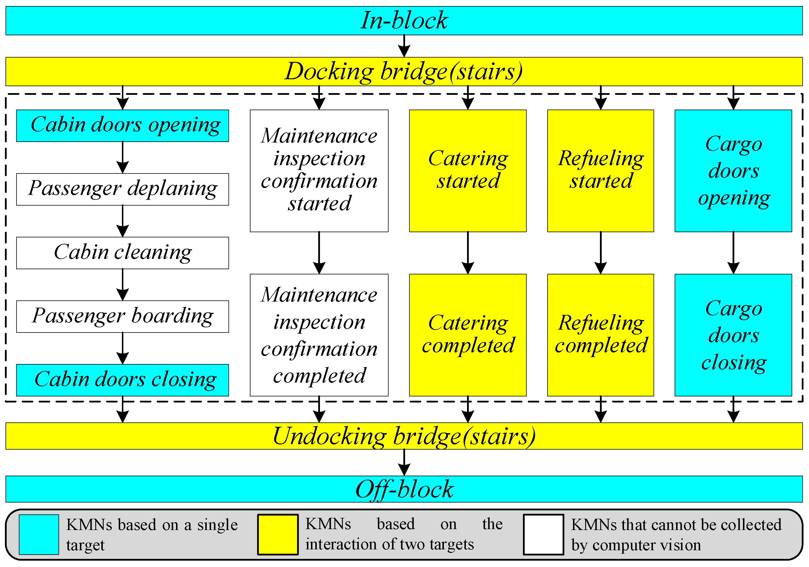
Aircraft turnaround can be defined as the process that unfolds from unloading an aircraft after its arrival until the departure of that aircraft as a new flight [1]. Depending on the regulations of Airport Collaborative Decision Making (A-CDM), the turnaround process can be quantified into a series of key milestone nodes (KMNs) [2,3]. The first KMN of an aircraft’s turn is referred to as the in-block node when the aircraft arrives at the parking position and after the chocks are set. The turnaround process ends when the aircraft is ready to depart. This end-time node is called an off-block node. In the period from the in-block time to the off-block time, there are several KMNs (shown in Figure 1) corresponding to different flight ground handling processes, such as catering, fueling, cabin opening and closing, and passenger deplaning and boarding. In recent years, the International Civil Aviation Organization (ICAO) and civil aviation authorities around the world have been vigorously improving the efficiency and resilience of airport operations by optimizing the use of resources and improving the predictability of air traffic and airport ground activities [4]. KMNs play a considerable role in airport planning, including schedule planning, fleet planning, and operation planning [5]. Therefore, collecting and recording node information by adopting automatic approaches can also improve the efficiency and quality of aircraft turnarounds. In this paper, a computer vision-based framework is established for the automatic collection of KMNs during the process of aircraft turnaround. The proposed framework automatically identifies the flight in/off-block and docking/undocking activities and records the corresponding KMNs, instead of employing the manual recording method used daily.
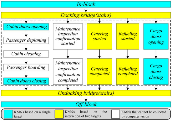
Figure 1.
KMNs in aircraft turnaround. The nodes in the dashed rectangle are parallel processes.
Existing systems of airport ground surveillance enable the monitoring of moving and parked targets mainly through target-positioning systems [6,7], such as Automatic Dependent Surveillance-Broadcast (ADS-B), Surface Movement Radar (SMR), and Multilateration (MLAT). The aforementioned systems, which mainly identify and label airport ground targets as point signals, are unable to effectively capture and extract semantic features and detailed information about moving and parked targets, and it is therefore difficult to use these systems to identify flight ground handling processes and collect corresponding KMNs. In recent years, computer vision-based surveillance systems have gained substantial popularity [8,9]. Two computer vision-based systems for airport ground surveillance, namely, INTERVUSE [10] and AVITRACK [11], were developed in the European Union at the turn of the century. With the development of digital tower conception over the last 20 years, current computer vision-based systems for airport ground surveillance have been exploited [12]. In brief, computer vision-based systems have three advantages in airport ground surveillance. First, computer vision-based systems have lower equipment investment costs than A-DSB, SMR, and MLAT. Second, unlike ADS-B and MLAT for cooperative target surveillance and SMR for noncooperative target surveillance, computer vision-based systems can monitor both cooperative and noncooperative ground targets. Third, computer vision-based surveillance uses vision sensors to capture images with rich semantic and detailed information, which is required for the identification of ground handling and corresponding KMNs.
From a methodological perspective of KMN collection by using computer vision, we roughly divide the KMNs listed in Figure 1 into two categories. The first category is the KMNs based on a single target, such as In-block, Off-block, Cabin doors open/close, and Cargo doors open/close. To address the problems of collecting KMNs of this category, the core task is to determine the moments when the position or state of the target changes through computer vision techniques. Another category is KMNs based on the interaction of two objectives, such as Docking/Undocking stairs, Catering start/completion, and Refueling start/completion. The key to solving the problem of collecting KMNs of the second category is to determine the moment of shift in the relative position between the subject and the object of a particular action. In addition, several KMNs in Figure 1 are outside the scope of the proposed framework for the following reasons: First, several KMNs cannot be captured comprehensively and entirely by ground surveillance cameras as activities corresponding to these KMNs do not take place or partially take place on the airport ground, e.g., Cabin cleaning, Maintenance inspection confirmation started/completed. Second, the boundaries of several KMNs are difficult to determine by approaches of computer vision, e.g., passenger deplaning/board. To this end, this paper aims to exploit a framework for the automatic collection of KMNs in the process of aircraft turnaround based on apron surveillance videos. The proposed framework can provide a general methodological architecture for the automatic collection of both categories of KMNs. The main work and contributions of this paper are summarized as follows.
(1) A computer vision-based framework for the automatic collection of KMNs is proposed. The framework consists mainly of two modules: a preprocessing module and a general methodological architecture for automatic collection.
(2) To extract spatiotemporal information of the executor of KMNs from the complex background of the airport ground, the preprocessing module is established by using a different loss function to improve the detector YOLO v5 and integrating the methods for prediction and association of each executor’s positions in consecutive frames.
(3) Based on the different characteristics of the KMNs, this paper divided them into two categories, i.e., nodes based on a single target and nodes based on the interaction of two targets, and two architectures are proposed for collecting nodes of in/off block and docking/undocking, respectively.
Moreover, for the training, testing, and evaluation of the proposed framework and related algorithms, related datasets captured on Beijing Capital International Airport were constructed. To the best of our knowledge, these datasets are the first dedicated to the automatic collection of KMNs.
The remainder of the paper is organized as follows. Section 2 introduces related works. The dataset and the main components of the proposed framework are described in Section 3. Section 4 and Section 5 detail the proposed framework. Section 6 reports on the related experiments. The conclusions and future work are summarized in Section 7.
2. Related Works
2.1. Collection of KMNs
The collection of KMNs is a prerequisite for determining whether a flight can be launched according to the normal flight schedule. The automatic collection of KMNs can help the airport operation control center to generate an optimal push-back sequence and improve the airport ground operational efficiency [13]. It is therefore crucial to implement A-CDM to establish the next generation of smart airport systems. Previous works on the KMNs of aircraft turnaround focused on the prediction of the operational situation based on historical and real-time shared data from the airport operation control center [14,15,16]. Nevertheless, it is difficult to construct effective predictive models due to the uncertainties and dynamics of the ground handling process.
Compared with research on node prediction, there have been few published academic papers on the automatic collection of KMNs. To the best of our knowledge, the Gate Activity Monitoring Tool Suite (GAMTOS) is one of the earliest tools that uses computer vision to monitor the turnaround process [17]. GAMTOS contains two modules. Specifically, the first module uses a deformable part model (DPM) [18] to detect different objects moving on the airport ground. The push-back time is predicted using a Bayesian framework in the second module. The DPM used in GAMTOS is computationally expensive, and the framework thus seems ineffective. As one of the pioneering and representative works in the field of automatic collection of KMNs, Thai et al. proposed a computer vision-based method of aircraft push-back prediction and turnaround monitoring [19]. They conducted the real scenarios tests by using surveillance videos of Obihiro Airport (IATA: OBO, ICAO: RJCB) [20]. Related experimental results show that its object detection model achieved up to 87.3% average precision (AP), and the average error of push-back prediction is less than 3 min. The other representative work was presented by Yıldız S et al. [21]. They set up a turnaround system to automatically detect and track ground services at the airport. In their work, ground services at airports are collected by using the motion status (stopping and moving) of the vehicles providing services. Moreover, Gorkow et al. offered a demo application of aircraft turnaround management using computer vision [22]. Undoubtedly, employing computer vision to complete KMN collection by detecting and tracking the ground support equipment (GSE) has become a consensus. Although the proposed framework follows a similar technical line, our approach differs from the two previous representative approaches in terms of implementation. The specific differences are detailed in Table 1. The above studies revealed that several tasks of GSE detection, recognition, localization, and movement state estimation are crucial parts of the computer vision-based automatic collection of KMNs. To this end, the present paper thus designs a novel preprocessing module to accomplish the above functions.

Table 1.
A brief comparison of the proposed work with the latest related works from the perspectives of the specific implementation.
2.2. Preprocessing for the Collection of KMNs
The aim of preprocessing is to extract spatiotemporal information of activity of the executors corresponding to different KMNs. Therefore, the first task of the proposed framework is to detect and identify these executors from the surveillance videos and thus obtain spatial information in the image plane. Based on this, the temporal motion information of the object is extracted by associating the same object in consecutive video frames. Therefore, detection and recognition are key aspects of the module of preprocessing for the collection of KMNs.
Object detection and recognition are hot and fundamental topics in the field of computer vision [23]. Before the emergence of deep learning-based detectors, handcrafted features, such as the histogram of oriented gradients [24] and scale-invariant feature transform [25], were used widely. One of the most representative handcrafted feature-based detectors is the DPM, which is based on histogram-of-oriented-gradients feature maps and has been applied in GAMTOS [17]. With the success of AlexNet [26], convolutional neural network-based models have become the mainstream in the field of object detection owing to their powerful capabilities of feature representation.
Existing deep learning-based detectors can generally be divided into two categories: two-stage and one-stage detectors. Two-stage methods have two steps, namely, region proposal generation and object classification. As a representative method of two-stage detectors, Faster RCNN was developed using the region proposal network as a proposal generator [27]. Many two-stage detectors based on the original Faster RCNN have been developed. In general, due to their computational complexity, two-stage detectors suffer from obvious shortcomings when applied to systems with high requirements for real-time performance. To address the real-time problem, region-free one-stage detectors have been proposed. They replace the results of the region proposal network by directly using each cell as a proposal and omit the proposal generation stage. In our opinion, AirNet proposed by Thai et al. belongs to a one-stage detector [20]. As the most widely used one-stage detectors at present, the first generation of the YOLO series was proposed in 2015 [28]. The greatest advantage of the original version of the YOLO series (e.g., YOLOv1, YOLOv2, and YOLOv3) is computational speed [29]. As new technologies (e.g., new backbones for feature map extraction and new modules for feature map fusion) are introduced into the YOLO framework, new members of the YOLO series with real-time performance with high accuracy are emerging all the time, such as YOLOv4 [30] and YOLOv5 [31]. In 2021, YOLOX is proposed by integrating recent outstanding developments in the field of object detection into the YOLOv5 [32]. Considering that the proposed framework has to work in real-time and requires accurate detection and identification of GSE and aircraft, we detect executors of ground activities corresponding to different KMNs by improving the loss function of YOLOv5.
3. Dataset Collection
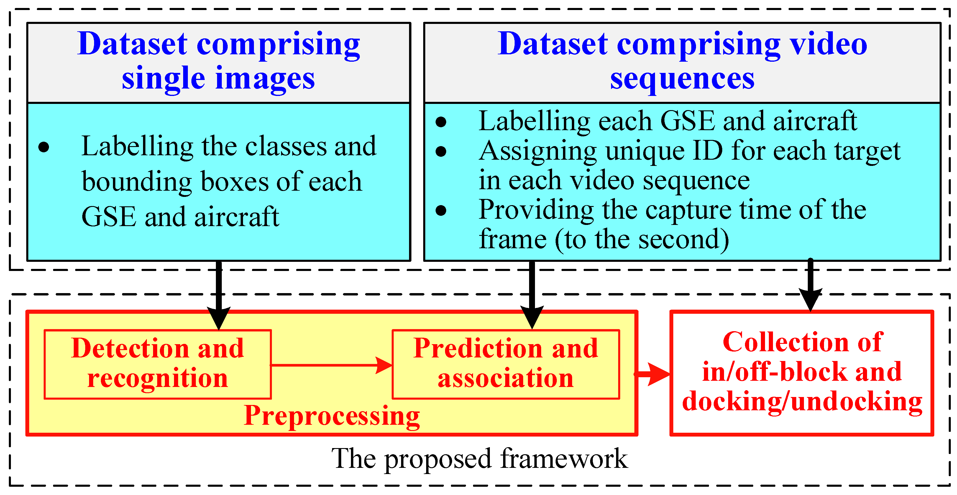
To complete the training and testing of the algorithms and the proposed framework, two datasets are constructed and presented. The first dataset consists of a large number of single-frame images, with the GSE and aircraft in each image being manually labeled using bounding boxes, and is used to train and evaluate the algorithm of the detection and recognition. The second dataset consists of video sequences of ground surveillance recorded at different times on two fixed stands at Beijing Capital International Airport and is used to evaluate the algorithm of object prediction and association as well as the collection of KMNs. In the second dataset, the bounding boxes and distinct IDs of each GSE and aircraft in each frame are also manually labeled for object prediction and association evaluation. Moreover, in the top left corner of each frame, the time (to the second) at which the frame was captured is displayed as the label to evaluate the collection of KMNs. The relationship between the datasets and each component of the proposed framework is shown in Figure 2.
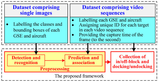
Figure 2.
Relationship between components of the proposed framework and our datasets.
3.1. Dataset Comprising Single Images
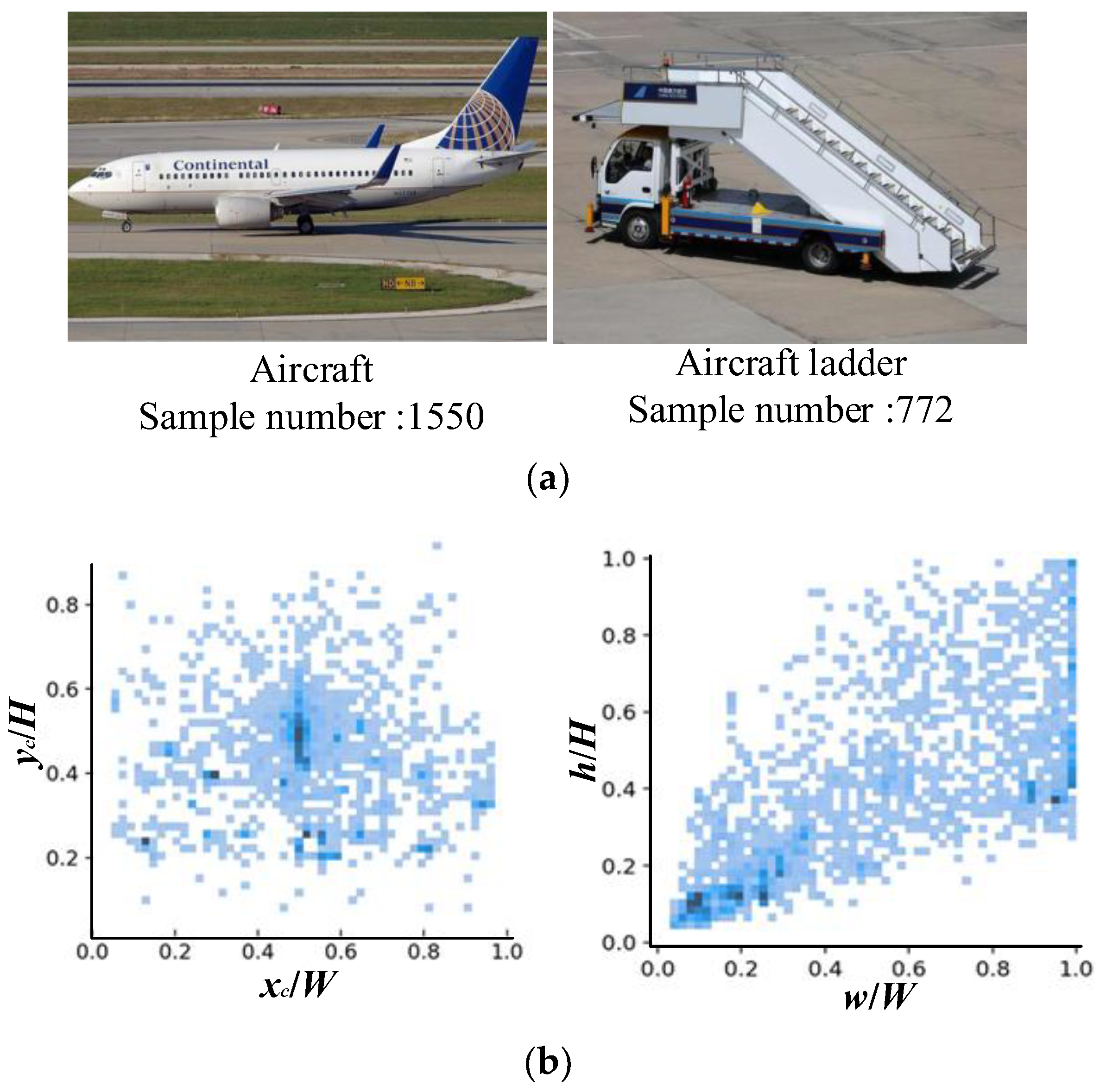
To detect and identify executors of KMNs during the turnaround process, a dataset consisting of 3175 images was first constructed. The dataset mainly contains civil aircraft and mobile aircraft landing stairs. Their numbers are presented in Figure 3a. To reflect a realistic airfield operational environment, images of the dataset cover several special cases, such as multi-scale changes in the targets, different visibilities, and occlusions. All targets are labeled manually, and each ground truth includes the location of the bounding boxes and their class names. The location and scale distribution of the objects in the dataset are shown in Figure 3b. This figure shows that the objects to be detected are mainly distributed in the central region of the image, and the scale distribution of the instances is relatively uniform.
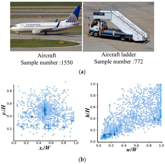
Figure 3.
Sample number of different categories and the location and scale distributions of the sample in the dataset. (a) Sample numbers of different categories. (b) Location and scale distributions of the samples in the dataset. For the location distribution (left), xc and yc are the horizontal and vertical coordinates of the center point of the bounding box of each object, respectively. W and H are the width and height of the image, respectively. For the scale distribution (right), w and h are the width and height of the bounding box of the object, respectively.
3.2. Dataset Comprising Video Sequences
Unlike the aforementioned dataset, which is an annotation of a single image, the second dataset is an annotation of a video sequence. Thus, in addition to annotating the bounding boxes and categories of the objects, this dataset also requires an ID number to be assigned to each target, with the same target having a constant ID in the sequence. This ID number is used to determine whether the same target has been successfully associated in different frames. Moreover, the dataset is used for the collection of KMNs and contains four KMN types, namely, aircraft in-block and off-block and the docking and undocking of mobile aircraft landing stairs.
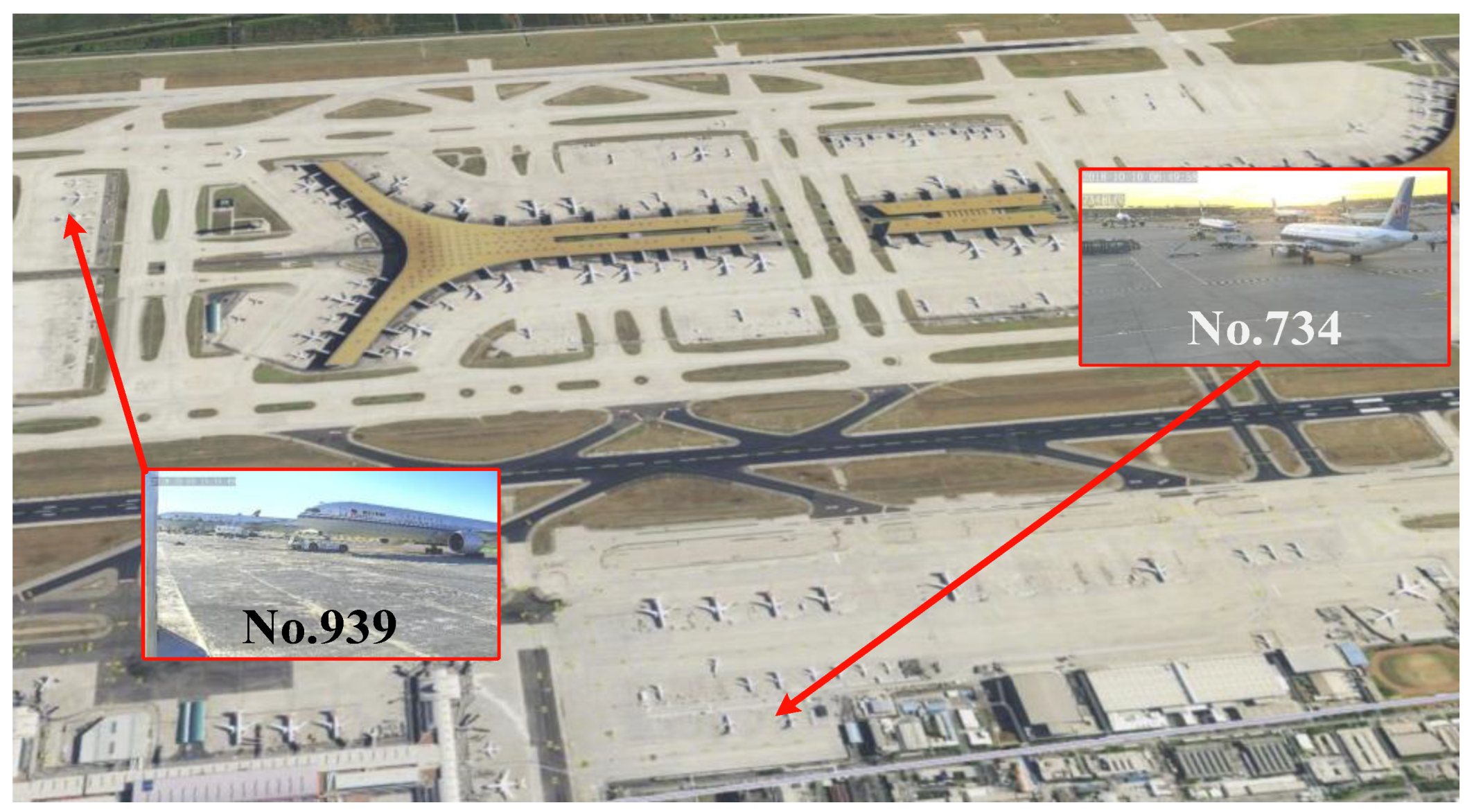
Original videos of this dataset were captured by surveillance cameras of two remote stands (No. 734 and No. 939) at Beijing Capital International Airport shown in Figure 4. The field of view of the camera at No. 734 is much larger than that of the camera at No. 939. The dataset contains 42 individual video sequences. Table 2 presents the distribution of video sequences. The frame index corresponding to the time of occurrence of the KMN is manually recorded as the ground truth to evaluate the proposed framework. The frame rate of the original video is 30 frames per second (fps). Owing to the relatively low speed of the aircraft and the motion of the various working vehicles in the surveillance video, not only does lowering the frame rate not affect the performance of the proposed framework but also it reduces memory consumption and improves operational efficiency to a certain extent. To this end, the original surveillance video is sampled at 5 fps, and each sequence of the dataset contains an average of 300 frames with a resolution of 1920 × 1080 pixels.
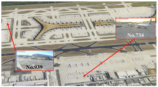
Figure 4.
Two remote stands at Beijing Capital International Airport (IATA: PEK, ICAO: ZBAA) where original videos of the dataset were captured.

Table 2.
Distribution of video sequences in the dataset.
4. Preprocessing Module
The purpose of the preprocessing module is to extract spatiotemporal information, including the identity, position, and movement states of executors of KMNs from the surveillance video, thus providing the necessary inputs for subsequent tasks of the collection of KMNs. The preprocessing module consists of three main parts: detection and recognition, prediction based on the filter, and association. Figure 5 is a flowchart of the preprocessing module.

Figure 5.
Flowchart of the preprocessing module.
4.1. Detection and Recognition
The identity and location information of the executors and participants of the KMNs are prerequisites for the completion of the collection of KMNs. A sub-module is thus required to accurately and in real-time detect and identify targets in specific areas of the airfield. The proposed framework utilizes YOLOv5 as the basic framework for GSE and aircraft detection and classification. YOLOv5 uses the architecture of Darknet53 with the Focus Structure and Cross Stage Partial Network as the backbone, PANet and SPP block as the neck, and the head containing three branches corresponding to outputs with three different scales [31]. The loss function of YOLOv5 consists of three parts and can be expressed as follows:
where the classification loss function Lcls is a cross-entropy loss function and used for classification and recognition, the confidence loss function Lobj is a binary cross entropy function used to determine whether an object exists within a projected bounding box, and the regression loss function Lreg is used to predict the bounding box regression. Considering that Lreg has a large impact on the positioning accuracy of the target, we compared four different methods for Lreg calculation: IoU-loss LIoU, Distance IoU-loss (DIoU-loss) LDIoU, Generalized IoU-loss (GIoU-loss) LGIoU, and Complete IoU-loss (CIoU-loss) LCIoU.
where and are the coordinates of the center points of the detected bounding box B and corresponding ground truth Bgt, respectively, E is the smallest enclosing box covering the detected bounding box and ground truth, L is the diagonal length of the E, and v is defined as [29],
where and are the width and height of Bgt, respectively, and w and h are the width and height of B, respectively. Through the comparative experiment (related results are shown in Table 4), CIoU-loss is used in the proposed framework to improve the positioning accuracy of the object. The reason for choosing CIoU-loss as the bounding box regression loss is that it takes into account two geometrical factors: the distance between the central points of bounding boxes and the aspect ratio of the bounding box.
4.2. Position Prediction
Detection can obtain the locations of each GSE and aircraft in a single frame, and associating the positions of the same target in consecutive frames is an indispensable precondition for the spatiotemporal information extraction for each target. Predicting the target position in the following frame based on the target position in the current frame can reduce both the search range and improve the accuracy of the match during association. To predict the target position, a state vector based on the detection results for a single frame is initialized [33]. x = [xc, yc, δ, h, Δxc, Δyc, Δδ, Δh]T, where δ = w/h, [xc, yc, δ, h] denotes the position and shape of the bounding box, and [Δxc, Δyc, Δδ, Δh] represents the change of state of objects between adjacent frames. The state-transition matrix is defined as
where, I4 × 4 and 04 × 4 are identity and zero matrixes with 4 × 4, respectively. The matrix of the transition from the state space to the observation space is C = [I4 × 4 04 × 4]. According to the state model in the t-1th frame, the estimated state model of the object in the tth frame is , where is a noise vector. According to the theory of Kalman filtering [34], the predicted result in the current frame is
where yt= [xc, yc, δ, h]T is the final result in the current frame that is obtained by detection and association. is the gain of the Kalman filter and is computed as
where R is the covariance matrix of the observation noise. is the predicted covariance matrix of the state vector in frame t and is calculated as
where W is the covariance matrix of the system noise, is the covariance matrix in the previous frame, and the covariance matrix Pt in the current frame needs to be updated according to . The initialization of the covariance matrix P0, R, and W for surveillance videos of No.734 and 939 are defined as
4.3. Association
In the current frame, the sub-module of detection and recognition obtains n bounding boxes , i = 1, 2,…, n. Moreover, according to the prediction result using the detection results of the previous frame, the predicted m bounding boxes are , j = 1, 2,…, m. We construct a matrix . The element ui,j of U denotes the value of IoU between two bounding boxes and . Therefore, a higher value of the element ui,j indicates a better match of and . In this paper, considering that the aircraft is moving slowly during the parking process, the aircraft has a larger IoU value between two adjacent frames compared with the GSE. We thus set a larger threshold Ta for the aircraft and a smaller threshold Tv for the vehicle to compute ui,j. Then, uij based on IoU is further constrained by the conditions
where class(.) denotes the category of the bounding box. Finally, the matrix U is used as the input of the Hungarian algorithm [35] to obtain the association results , , and if and are associated.
5. Collection of KMNs
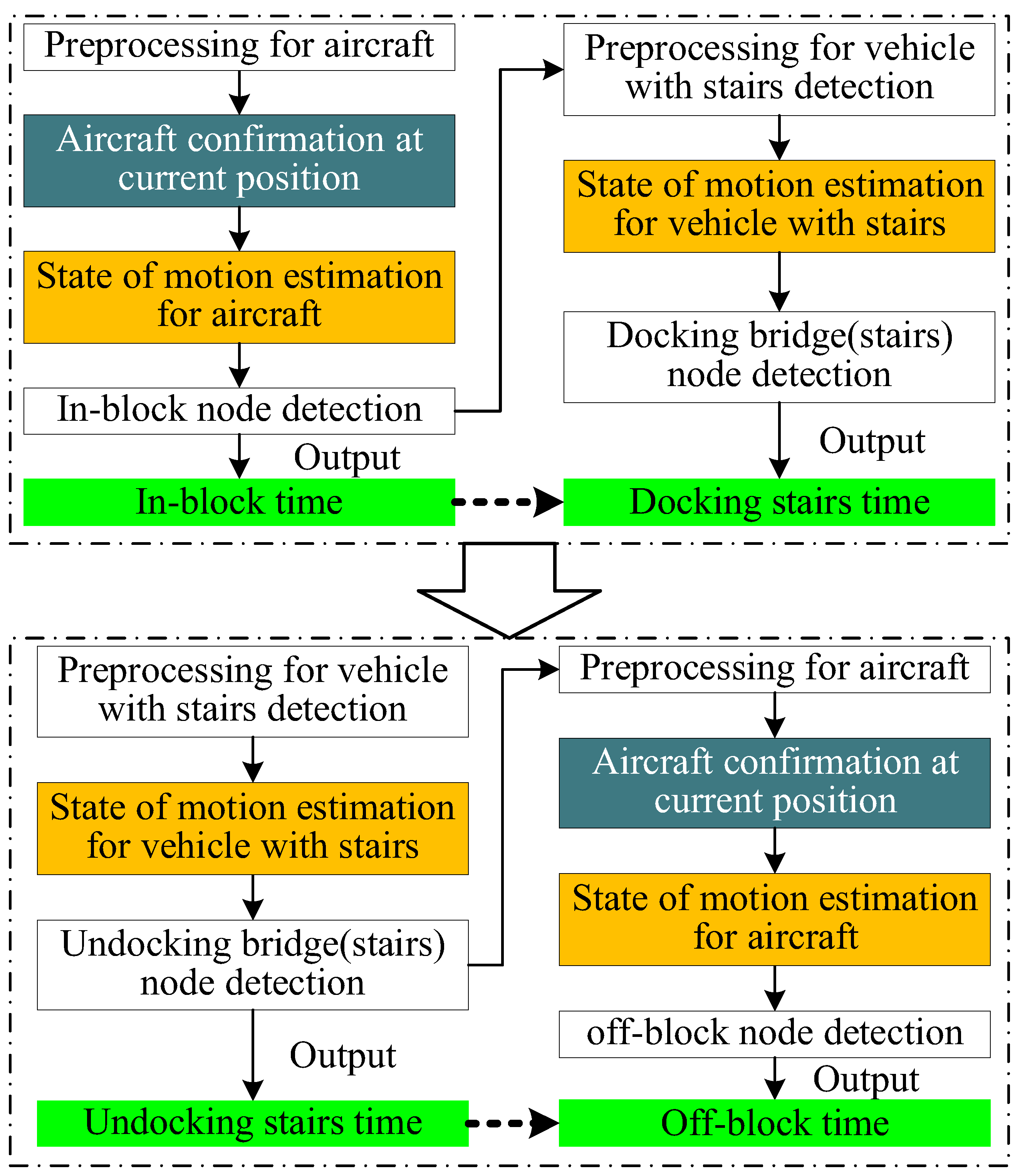
As mentioned above, the KMNs defined in A-CDM can be divided into two categories: nodes based on the actions of a single target and nodes based on the interactions of two targets. In this paper, we use four KMNs as examples to develop the framework for the automatic collection of KMNs. Among these four KMNs, in-block and off- block are representative of the action of a single target, whereas docking and undocking stairs are representatives of the interaction between the parked aircraft and moving aircraft landing stairs. Figure 6 shows the flowchart of the automatic collection of four KMNs. In the flowchart, there are four key issues to address: (1) Aircraft confirmation at the current position; (2) Motion state estimation for a single target (including aircraft and GSE); (3) Collection of KMNs based on a single target; (4) Collection of KMNs based on multi-object interaction. In this section, we discuss related issues using surveillance videos captured by the fixed cameras at positions 939 and 734.
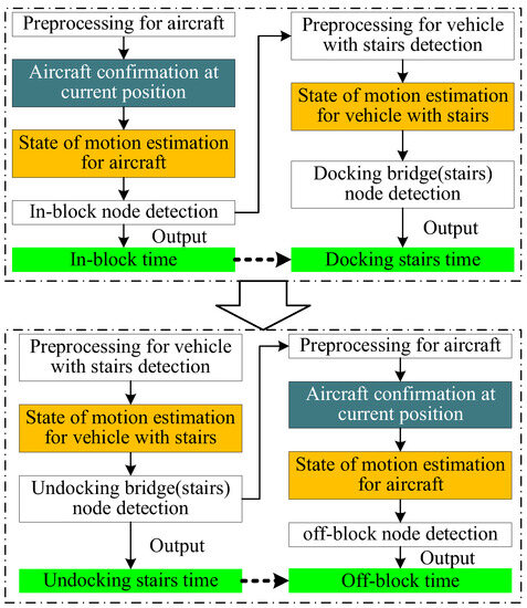
Figure 6.
Flowchart of the automatic collection of four KMNs.
5.1. Aircraft Confirmation at the Current Position
Existing cameras for airport parking surveillance are located at fixed locations and are used to monitor activities at individual aircraft stands. However, due to the different field of view of the surveillance cameras, aircraft in adjacent parking positions may be included in one surveillance image. Since all ground service work revolves around the aircraft in its current parking position, it is thus necessary to first identify and confirm the aircraft in the current position from all detected aircraft in the surveillance video. By analyzing the size of the aircraft in the image plane at positions No. 734 and No. 939, we find that the width or height of the bounding box of the aircraft at the current position is at least half of the width or height of the image plane. According to this prior rule, Algorithm 1 is designed to confirm the aircraft at its current position. The aircraft at the current position is determined by searching the bounding box of the aircraft with the largest area that satisfying the above rule. Figure 7 shows the results of aircraft confirmation.
| Algorithm 1. Aircraft confirmation at the current position |
| Inputs: bounding boxes of aircraft , i = 1, 2, …, n. W and H are the width and height of the input image, respectively. for i = 1:n if wi>W/2 or hi > H/2 Si = wi × hi else Si = 0 end if end for Outputs: the bounding box of the aircraft at current position is . |

Figure 7.
Results of aircraft confirmation at the current position. Blue rectangles are the bounding boxes of the aircraft confirmed by Algorithm 1.
5.2. Motion State Estimation for a Single Target
Determining whether an aircraft or a GSE is stationary is the key to the automatic collection of KMNs. Motion-state estimation for a single target is employed to address this issue. The position and size of the bounding box are constantly changing during the movement of airport ground targets. In determining whether the target is in motion or at rest, we use the standard deviations of the center point coordinates of the bounding box and the IoUpc values of the previous and current bounding boxes in consecutive frames of a certain length to determine the motion state. We define the precondition for the target to be in a stationary state at tth frame as
C1(t) = 1 indicates that the target is in a stationary state. Thc and ThIoU are thresholds of σc and , respectively. and are calculated as
where r is the radius of the video sequence with a length of 2r + 1, and the tth frame is the center of this video sequence. Moreover,
Here, σx(t) and σy(t) are the standard deviations of the center point coordinates of the bounding box along the x-axis and y-axis directions of the image plane. is the standard deviation of IoUpc. Bi−1 and Bi are bounding boxes of the target in previous and current frames, respectively.
5.3. Collection of KMNs Based on a Single Target
We illustrate the collection of KMNs based on a single target by using the examples of in-block and off-block of an aircraft. In-block means that an aircraft has arrived in the parking position and parking brakes are activated. Thus, in-block of the aircraft is the transition of the aircraft’s state from motion to rest. In contrast, off-block is the moment when an aircraft starts to move from the parking position and prepares to taxi and take off. This implies that off-block is the transition from the stationary to the moving state of the aircraft. Consequently, nodes of in-block and off-block can be detected based on the motion state estimation of a single target. The algorithm for in-block and off-block node detection is described in Algorithm 2. Without loss of generality, this algorithm can be used to collect other KMNs based on a single target.
| Algorithm 2. In-block and off-block node collection |
| Inputs: For a sequence with num frames, the bounding box of aircraft in each frame is , i = 1,2,…,num. Thc and ThIoU of Equation (10) are initialized (manually determined). for t = r + 2:num-r-1 Computing and , and , and . Computing C1(t − 1), C1(t), and C1(t + 1) using Condition 1 of Equation (10). if C1(t − 1) = 0 and C1(t) = 1 and C1(t + 1) = 1 In-block node is t. else if C1(t − 1) = 1 and C1(t) = 0 and C1(t + 1) = 0 Off-block node is t. end if end for Outputs: In-block and off-block nodes. |
5.4. Collection of KMNs Based on Multi-Object Interaction
Unlike in-block and off-block node detection, which only needs to focus on the movement of the aircraft at the current position, docking and undocking stairs node collection needs to determine the movement of the mobile aircraft landing stairs while also analyzing the positional relationship between the mobile aircraft landing stairs and the parked aircraft. Condition 1 of Equation (10) can be used to determine the movement of the mobile aircraft landing stairs. Figure 8 reveals that the bounding boxes of the movable aircraft landing stairs are contained in the bounding box of the parked aircraft. Therefore, in order to represent the position relationship between the mobile aircraft landing stairs and the parked aircraft, the index IoUav is proposed and expressed as
where Ba and Bv are the bounding boxes of the parked aircraft and the movable aircraft landing stairs, respectively. When Bv is completely contained within the boundaries of Ba, IoUav = 1.

Figure 8.
Positional relationship between the mobile aircraft landing stairs and parked aircraft.
The above observations indicate that there are two conditions for the docking of the parked aircraft and ground vehicles in the tth frame. The first condition is that the ground vehicle is in a stationary state that can be confirmed by Condition 1. The second condition reflects the positional relationship between the mobile aircraft landing stairs and the parked aircraft and is defined as
On the basis of the two preconditions, the docking and undocking stairs node collection is demonstrated in Algorithm 3. Without loss of generality, this algorithm can be used to collect other KMNs based on multi-object interaction.
| Algorithm 3. Docking and undocking stairs node detection |
| Inputs: For a sequence with num frames, and are the bounding boxes of aircraft and mobile aircraft landing stairs in each frame, respectively, i = 1,2, …, num. Thc and ThIoU are the thresholds of σc and σIoU of Condition 1, respectively. for t = r + 2:num – r − 1 Computing Condition 2 C2(t) using and if C2(t) = 1 Using the bounding boxes of mobile aircraft landing stairs and Condition 1 to compute C1(t − 1), C1(t), and C1(t + 1). if C1(t − 1) = 0 and C1(t) = 1 and C1(t + 1) = 1 Docking node is t. else if C1(t − 1) = 1 and C1(t) = 0 and C1(t + 1) = 0 Undocking node is t. end if end if end for Outputs: Docking and undocking stairs nodes. |
6. Experimental Results and Analysis
Experiments were conducted to evaluate the performances of the proposed framework and modules. The related algorithms are executed on a GPU server equipped with an Intel(R) Xeon E51620 v3 CPU@3.50GHz×8, 64.0 GB of RAM, and NVIDIA GTX 1080Ti 12GB. We train and implement the proposed framework in Python 3.6.12 and CUDA 10.1.
6.1. Experimental Results of Detection and Recognition
The parameter settings of the algorithm used for detection and recognition training are summarized as follows. The training, validation, and test dataset are 60%, 20%, and 20%, respectively. The number of epochs is 30, and the batch size is 16. The weight decay rate was set to 0.0005, the momentum to 0.937, and the initial and final learning rates to 0.1 and 0.01, respectively. The following widely used metrics are adopted for the quantitative assessment of the performance of the algorithm of detection and recognition [36].
- (1)
- PrecisionC
- (2)
- RecallC
- (3)
- Mean Average Precision (mAP)
The precision values corresponding to all recall points under the precision–recall curve are averaged to calculate the average precision (AP). Furthermore, the average of AP across all classes is mAP.
Here, a true positive (TP) refers to the scenario that the actual class is positive, and the class predicted by the algorithm is also positive. A false positive (FP) and false negative (FN) refer to falsely predicted positive and negative values, respectively. C denotes the different categories.
Table 3 gives the evaluation results on our dataset for five classes of target. From this table, we can observe that mAP values are above 90% for both two target categories. Compared with aircraft detection, the detection performance of movable aircraft landing stairs do not perform as well as the former. In our opinion, this result is due to the shape diversity of mobile aircraft landing stairs (as shown in Figure 9). Table 4 lists the results of comparative experiments using different IoU losses, namely, IoU-loss, GIoU-loss, DIoU-loss, and CIoU-loss, in our sub-module of detection and recognition. In Table 4, although the Recall value for CIoU-loss is slightly worse than that for GIoU-loss, CIoU-loss outperforms the other two losses in terms of precision and mAP. Therefore, the detection module of the proposed framework uses CIoU-loss as the regression loss.

Table 3.
Performance metrics of the sub-module of detection and recognition.

Figure 9.
Detection and recognition of targets of the same class with different appearances.

Table 4.
Comparative experiments using different Lreg.
6.2. Experimental Results of the Prediction and Association
In this experiment, the following metrics provided in the MOT Challenge Benchmark are used to evaluate the performance of prediction and association. (1) Multi-object tracking accuracy (MOTA):
where num is the frame number of the sequence, and GTt and IDSWt are the number of ground-truth objects and the number of ID switches for all objects in the tth frame of the sequence, respectively.
(2) Multiple object tracking precision (MOTP)
where ct is the number of objects associated successfully in the tth frame, and IoUi,t is the bounding box overlap of the ith successfully associated object with the ground-truth object in the tth frame.
In Equation (9), the threshold Ta for the aircraft and Tv are set at 0.95 and 0.9, respectively. We select eight sets of video sequences from the dataset for experiments. These sequences consist of four types of KMN: in-block, off-block, docking stairs, and undocking stairs. The results of the quantitative assessment for eight test samples are given in Table 5. The experimental results show that the sub-module of the prediction and association used in our framework has only 33 ID switches owing to target association errors, whereas there are a total of 8397 objects detected. Specifically, the association success rate is high, with the average MOTA of 95.09%, and the localization accuracy is high, with the average MOTP of 92.63%.

Table 5.
Association results of the quantitative assessment for eight video sequences.
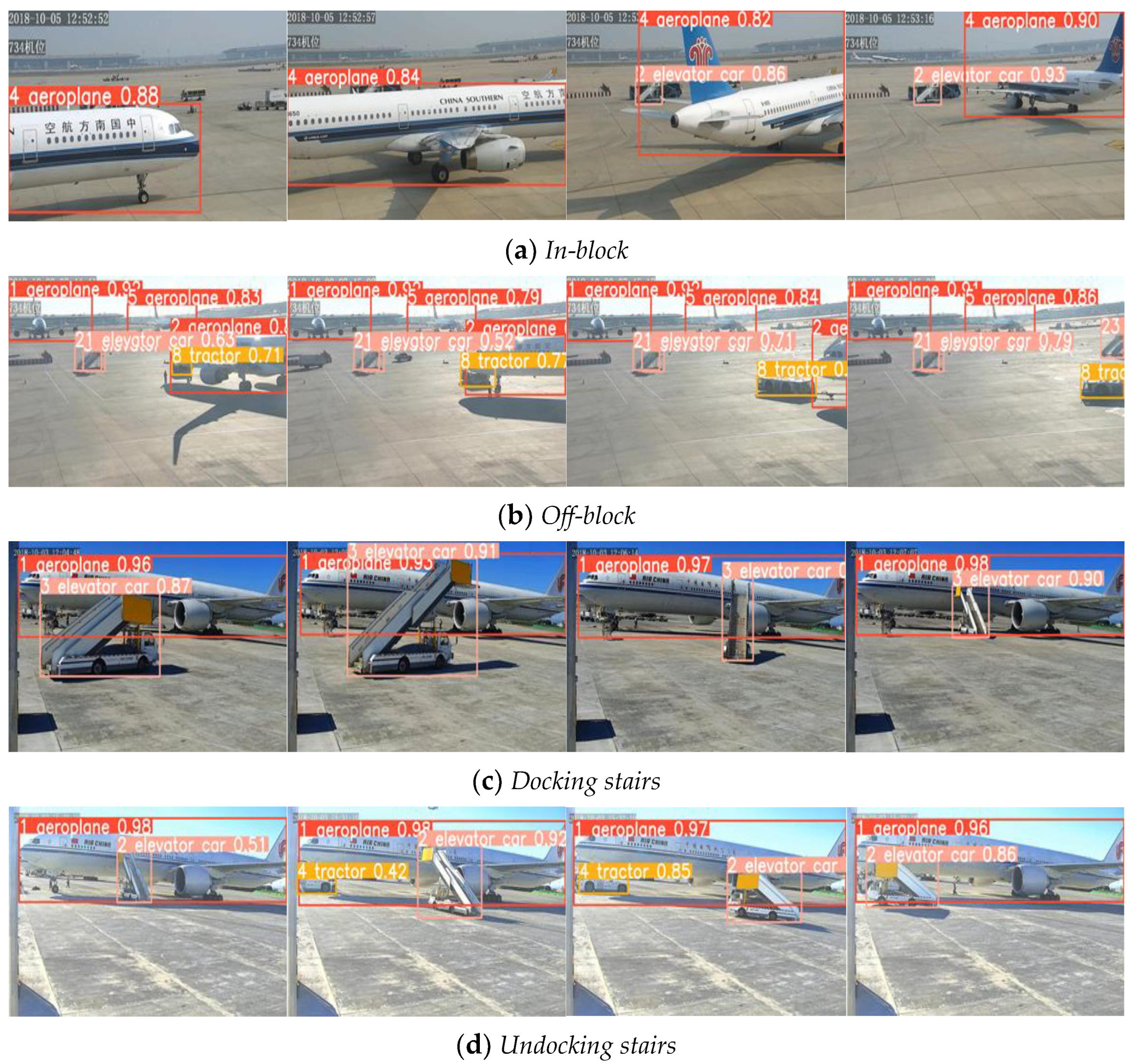
Figure 10 shows several correlation results for qualitative analysis. The results for in-block reveal that the appearance of the aircraft varies considerably due to the number of turns required during in-block, but the aircraft ID number remains constant throughout this process. Similar results for off-block, docking stairs, and undocking stairs indicate that our method maintains association robustness in response to deformation. In Figure 10b, there are multiple targets such as craters, tractors, and aircraft. However, the ID of each target remains the same, indicating that the sub-module of the prediction and association remains robust against the complex background of the airport ground.
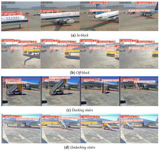
Figure 10.
Association results of four video sequences.
6.3. Experimental Results of the Collection of KMNs
KMNs are collected using the preprocessing module. The collection is evaluated according to the results of the above experiments. We tested all 42 video sequences from the dataset comprising video sequences. The ground truth of each KMN in the testing videos is manually annotated by a professional from the airport surface service department. The frame error (FE) and corresponding time error (TE) are used to quantitatively evaluate the performance:
where Ni is the frame index obtained by the proposed algorithm and is the corresponding ground truth. L is the number of test sequences. The frequency of the video sequence captured in the dataset is 5 fps, and the time interval between the current frame and the previous is thus 0.2 s. The (empirical) parameter settings are r = 5, Thc = 5, and ThIoU = 0.1 for the aircraft and Thc = 3 and ThIoU = 0.05 for the mobile aircraft landing stairs.
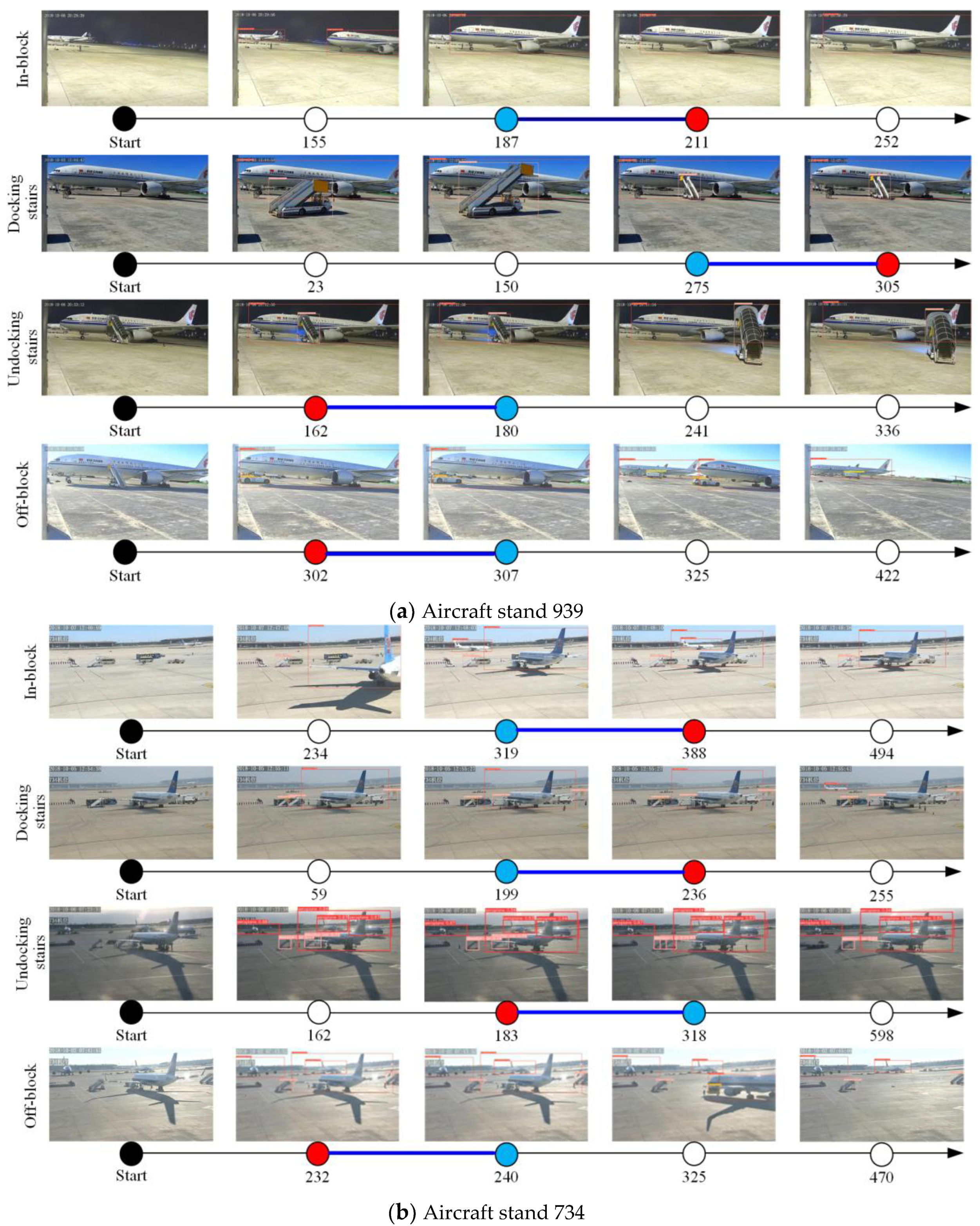
Results of quantitative evaluation are listed in Table 6. Figure 11a,b show the results of the collection of the four types of KMN at aircraft stands 939 and 734, respectively. In the figure, each time axis represents a time series in terms of the number of frame. The time axis is labeled with the origin and the total number of frames, and the predicted nodes of activity occurrence are shown as red dots, the actual nodes of activity occurrence are shown as blue dots, and the white dots are the process nodes of activity occurrence. The following observations are made from the aforementioned results. First, the error is largest for the in-block node. This is because aircraft have a larger bounding box compared with vehicles, making it more difficult to determine changes in aircraft movement. Second, the error at position 734 is slightly higher than that at position 939. This is due to more interference around position 734, which is farther away from the camera, and less interference around position 939, where the positioning information is more accurate. Third, the timing error in the automatic collection of KMNs is well below 60 s, as required by the A-CDM system. To sum up, since all of these test samples were from the 734 and 939 aircraft positions at Beijing Capital Airport, we believe that the proposed framework can be applied directly to KMN collection of these two aircraft stands.

Table 6.
Quantitative evaluation of the automatic collection of KMNs.
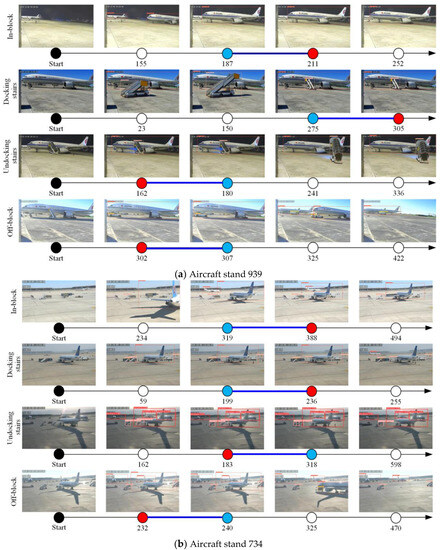
Figure 11.
Results of the automatic collection of four KMNs.
It is well known that results of the collection of KMNs using the proposed framework depended on the change in the position and movement state of the executor of key milestone nodes. Therefore, timing error in the automatic collection of KMNs mainly comes from the extraction accuracy of the spatiotemporal information of the executor. Due to the complex background of the airport ground, it is difficult to improve this accuracy and thus reduce the timing error of KMN collection by only using the spatiotemporal information from the surveillance cameras. Consequently, in future work, it is essential to introduce heterogeneous information from other sensors (e.g., LIDAR, etc.) to improve the extraction accuracy of the spatiotemporal information of the executor, while ensuring the operational safety of the airport ground. Furthermore, it must also be pointed out that several thresholds in the module of collection of KMNs presented in this paper are preset according to the situation of aircraft stands 939 and 734 of Beijing Capital Airport. Since these thresholds are closely related to the distance between the aircraft and the camera, the size of the image resolution, etc., they are not universal and have to be recalibrated manually when the distance between the surveillance camera and the target or when the camera parameters change.
7. Conclusions and Future Work
The automatic collection of key milestone nodes in the process of aircraft turnaround plays an important role in terms of upgrading the intelligence of airport ground operations. The main purpose of this study was to exploit a framework of the automatic collection of four KMNs in the process of aircraft turnaround based on apron surveillance videos. To achieve this goals, two datasets of imagery captured at Beijing Capital International Airport were firstly established to train, test, and assess the proposed framework and related algorithms. Secondly, to extract spatiotemporal information of the executors of KMNs from the complex background of the airport ground, a preprocessing module seamlessly integrating state-of-the-art detection and tracking algorithms was proposed. Specifically, a detector which uses the CIoU-loss function to improve the positioning accuracy of the object in the YOLOV5 was designed. Moreover, the sub-modules of prediction and association were combined with the detector to improve both the accuracy and real-time performance of the spatiotemporal feature extraction. Thirdly, for the nodes based on the action of a single target (represented by in-block and off-block) and the interaction of two targets (represented by docking and undocking stairs), two approaches of automatic collection of KMNs were proposed. Experimental results on the two remote stands (No.734 and No.939) of Beijing Capital International Airport showed that the timing error of the proposed framework was well under 60 s, meeting the requirements of the A-CDM system.
Although we initially assessed the proposed framework and found it to be promising, there is still a lot of room for further development. First, instance segmentation-based methods will be developed to obtain more accurate target bounds. Second, as the datasets is further expanded, deep learning-based action localization methods will be investigated to further improve the robustness and accuracy of the automatic collection of KMNs against complex background on the airport grounds. Moreover, the autonomous selection of the thresholds of Algorithms 2 and 3 is also one of the important tasks in the future work.
Author Contributions
Conceptualization, J.X. and M.D.; methodology, M.D.; software, Z.-Z.Z.; validation, J.X. and F.Z.; formal analysis, Y.-B.X.; writing—original draft preparation, J.X.; writing—review and editing, M.D.; visualization, M.D. and Z.-Z.Z.; supervision, M.D. and X.-H.W.; project administration, M.D. All authors have read and agreed to the published version of the manuscript.
Funding
This work is co-supported by the National Natural Science Foundation of China (No. U2033201). It is also supported by the Opening Project of Civil Aviation Satellite Application Engineering Technology Research Center (RCCASA-2022003) and Innovation Fund of COMAC (GCZX-2022-03).
Institutional Review Board Statement
Not applicable.
Informed Consent Statement
Not applicable.
Data Availability Statement
The data presented in this study are available in the article.
Conflicts of Interest
The authors declare no conflict of interest.
References
- Li, B.; Wang, L.; Xing, Z.; Luo, Q. Performance Evaluation of Multiflight Ground Handling Process. Aerospace 2022, 9, 273. [Google Scholar] [CrossRef]
- A-CDM Milestones, Mainly the Target off Block Time (TOBT). Available online: http://www.eurocontrol.int/articles/air-portcollaborative-decision-making-cdm (accessed on 3 March 2023).
- More, D.; Sharma, R. The turnaround time of an aircraft: A competitive weapon for an airline company. Decision 2014, 41, 489–497. [Google Scholar] [CrossRef]
- Airport-Collaborative Decision Making (A-CDM): IATA Recommendations. Available online: https://www.iata.org/contentassets/5c1a116a6120415f87f3dadfa38859d2/iata-acdm-recommendations-v1.pdf (accessed on 5 March 2023).
- Wei, K.J.; Vikrant, V.; Alexandre, J. Airline timetable development and fleet assignment incorporating passenger choice. Transp. Sci. 2020, 54, 139–163. [Google Scholar] [CrossRef]
- Tian, Y.; Liu, H.; Feng, H.; Wu, B.; Wu, G. Virtual simulation-based evaluation of ground handling for future aircraft concepts. J. Aerosp. Inf. Syst. 2013, 10, 218–228. [Google Scholar] [CrossRef]
- Perl, E. Review of Airport Surface Movement Radar Technology. IEEE Aerosp. Electron. Syst. Mag. 2006, 21, 24–27. [Google Scholar] [CrossRef]
- Xiong, Z.; Li, M.; Ma, Y.; Wu, X. Vehicle Re-Identification with Image Processing and Car-Following Model Using Multiple Surveillance Cameras from Urban Arterials. IEEE Trans. Intell. Transp. Syst. 2020, 22, 7619–7630. [Google Scholar] [CrossRef]
- Zhang, C.; Li, F.; Ou, J.; Xie, P.; Sheng, W. A New Cellular Vehicle-to-Everything Application: Daytime Visibility Detection and Prewarning on Expressways. IEEE Intell. Transp. Syst. Mag. 2022, 15, 85–98. [Google Scholar] [CrossRef]
- Besada, J.A.; Garcia, J.; Portillo, J.; Molina, J.M.; Varona, A.; Gonzalez, G. Airport Surface Surveillance Based on Video Images. IEEE Trans. Intell. Transp. Syst. 2005, 41, 1075–1082. [Google Scholar]
- Thirde, D.; Borg, M.; Ferryman, J. A real-time scene understanding system for airport apron monitoring. In Proceedings of the IEEE International Conference on Computer Vision System, New York, NY, USA, 4–7 January 2006. [Google Scholar]
- Zhang, X.; Qiao, Y. A video surveillance network for airport ground moving targets. In Proceedings of the International Conference on Mobile Networks and Management, Chiba, Japan, 10–12 November 2020; pp. 229–237. [Google Scholar]
- Netto, O.; Silva, J.; Baltazar, M. The airport A-CDM operational implementation description and challenges. J. Airl. Airpt. Manag. 2020, 10, 14–30. [Google Scholar] [CrossRef]
- Simaiakis, I.; Balakrishnan, H. A queuing model of the airport departure process. Transp. Sci. 2016, 50, 94–109. [Google Scholar] [CrossRef]
- Voulgarellis, P.G.; Christodoulou, M.A.; Boutalis, Y.S. A MATLAB based simulation language for aircraft ground handling operations at hub airports (SLAGOM). In Proceedings of the 2005 IEEE International Symposium on Mediterrean Conference on Control and Automation Intelligent Control, Limassol, Cyprus, 27–29 June 2005; pp. 334–339. [Google Scholar]
- Wu, C.L. Monitoring aircraft turnaround operations–framework development, application and implications for airline operations. Transp. Plan. Technol. 2008, 31, 215–228. [Google Scholar] [CrossRef]
- Lu, H.L.; Vaddi, S.; Cheng, V.V.; Tsai, J. Airport Gate Operation Monitoring Using Computer Vision Techniques. In Proceedings of the 16th AIAA Aviation Technology, Integration, Operations Conference, Washington, DC, USA, 13–17 June 2016. [Google Scholar]
- Felzenszwalb, P.F.; Girshick, R.B.; McAllester, D.; Ramanan, D. Object detection with discriminatively trained part based models. IEEE Trans. Pattern Anal. Mach. Intell. 2010, 32, 1627–1645. [Google Scholar] [CrossRef] [PubMed]
- Thai, P.; Alam, S.; Lilith, N.; Phu, T.N.; Nguyen, B.T. Aircraft Push-back Prediction and Turnaround Monitoring by Vision-based Object Detection and Activity Identification. In Proceedings of the 10th SESAR Innovation Days, Online, 7–10 December 2020. [Google Scholar]
- Thai, P.; Alam, S.; Lilith, N.; Nguyen, B.T. A computer vision framework using Convolutional Neural Networks for airport-airside surveillance. Transp. Res. Part C Emerg. Technol. 2022, 137, 103590. [Google Scholar] [CrossRef]
- Yıldız, S.; Aydemir, O.; Memiş, A.; Varlı, S. A turnaround control system to automatically detect and monitor the time stamps of ground service actions in airports: A deep learning and computer vision based approach. Eng. Appl. Artif. Intell. 2022, 114, 105032. [Google Scholar] [CrossRef]
- Available online: https://medium.com/@michaelgorkow/aircraft-turnaround-management-using-computer-vision-4bec29838c08 (accessed on 6 March 2023).
- Zaidi SS, A.; Ansari, M.S.; Aslam, A.; Kanwal, N.; Asghar, M.; Lee, B. A survey of modern deep learning based object detection models. Digit. Signal Process. 2022, 26, 103514. [Google Scholar] [CrossRef]
- Dalal, N.; Triggs, B. Histograms of Oriented Gradients for Human Detection. In Proceedings of the IEEE Conference on Computer Vision and Pattern Recognition, San Diego, CA, USA, 20–25 June 2005; pp. 886–893. [Google Scholar]
- Lowe, D.G. Distinctive Image Features from Scale-Invariant Keypoints. Int. J. Comput. Vis. 2004, 60, 91–110. [Google Scholar] [CrossRef]
- Krizhevsky, A.; Sutskever, I.; Hinton, G.E. ImageNet Classification with Deep Convolutional Neural Networks. Commun. ACM 2012, 60, 84–90. [Google Scholar] [CrossRef]
- Ren, S.; He, K.; Girshick, R.; Sun, J. Faster R-CNN: Towards Real-Time Object Detection with Region Proposal Networks. IEEE Trans. Pattern Anal. Mach. Intell. 2017, 39, 1137–1149. [Google Scholar] [CrossRef]
- Redmon, J.; Divvala, S.; Girshick, R.; Farhadi, A. You Only Look Once: Unified, Real-Time Object Detection. In Proceedings of the 2015 IEEE Conference on Computer Vision and Pattern Recognition, Boston, MA, USA, 26 June–1 July 2015; pp. 779–788. [Google Scholar]
- Redmon, J.; Farhadi, A. YOLOv3: An Incremental Improvement. arXiv 2018, arXiv:1804.02767. [Google Scholar]
- Bochkovskiy, A.; Wang, C.Y.; Mark Liao, H.Y. YOLOv4: Optimal speed and accuracy of object detection. arXiv 2020, arXiv:2004.10934. [Google Scholar]
- Kasper-Eulaers, M.; Hahn, N.; Berger, S.; Sebulonsen, T.; Myrland, Ø.; Kummervold, P.E. Detecting heavy goods vehicles in rest areas in winter conditions using YOLOv5. Algorithms 2021, 14, 114. [Google Scholar] [CrossRef]
- Ge, Z.; Liu, S.; Wang, F.; Li, Z.; Sun, J. Yolox: Exceeding yolo series in 2021. arXiv 2021, arXiv:2107.08430. [Google Scholar]
- Wu, H.; Du, C.; Ji, Z.; Gao, M.; He, Z. SORT-YM: An Algorithm of Multi-Object Tracking with YOLOv4-Tiny and Motion Prediction. Electronics 2021, 10, 2319. [Google Scholar] [CrossRef]
- Kalman, R.E. A New Approach to Linear Filtering and Prediction Problems. J. Basic Eng. 1960, 82, 35–45. [Google Scholar] [CrossRef]
- Kuhn, H.W. The Hungarian method for the assignment problem. Nav. Res. Logist. Q. 1955, 2, 83–97. [Google Scholar] [CrossRef]
- Davis, J.; Goadrich, M. The relationship between Precision-Recall and ROC curves. In Proceedings of the 23rd International Conference on Machine Learning, New York, NY, USA, 25–29 June 2006; pp. 233–240. [Google Scholar]
Disclaimer/Publisher’s Note: The statements, opinions and data contained in all publications are solely those of the individual author(s) and contributor(s) and not of MDPI and/or the editor(s). MDPI and/or the editor(s) disclaim responsibility for any injury to people or property resulting from any ideas, methods, instructions or products referred to in the content. |
© 2023 by the authors. Licensee MDPI, Basel, Switzerland. This article is an open access article distributed under the terms and conditions of the Creative Commons Attribution (CC BY) license (https://creativecommons.org/licenses/by/4.0/).

